1
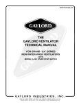
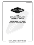
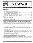
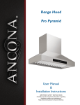
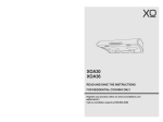
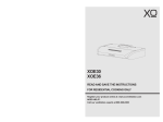
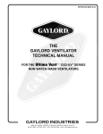
2012 Introduction to the Exhaust Fan Interceptor Commercial Exhaust Fans from a Service Perspective © 2012 - Superior Restaurant Services 3/21/2012 © 2012 - Superior Restaurant Services | 2 Contents Introduction .............................................................................................................................................. 4 Commercial Exhaust System Design ......................................................................................................... 5 Fire Code Requirements ........................................................................................................................... 7 Kitchen Ventilation Cleaning Process ..................................................................................................... 10 The Exhaust Fan Drain Spout .................................................................................................................. 12 Exhaust Fan Grease Discharge ................................................................................................................ 13 Environmental Requirements ................................................................................................................. 14 How the EFI Works .................................................................................................................................. 15 EFI Service ............................................................................................................................................... 17 Training ................................................................................................................................................... 18 Summary ................................................................................................................................................. 19 © 2012 - Superior Restaurant Services | 3 Introduction This document will introduce a standard commercial exhaust fan design, fire protection requirements, some of the service issues regarding commercial exhaust fans and introduce Superior Restaurant Services Exhaust Fan Interceptor (EFI). With an Exhaust fan interceptor we are able to achieve roof protection and waste water recovery during service. Eliminating the two industry problems in one product has never been accomplished before. The technique discovered to recover waste has never been so simple, there is no mechanical process involved so its continuous function is almost guaranteed. The EFI’s product strength is that it enables full waste recovery from the fan cleaning process with a standard length of hose. No special equipment is required. There is no need for filters, so supply and replacement is not an issue. © 2012 - Superior Restaurant Services | 4 Commercial Exhaust System Design A typical kitchen ventilation system includes an exhaust hood or canopy, ductwork, fan system, and a means of providing adequate make-up air. The entire system must constitute a fire-safe assembly within the building. Exhaust hoods and canopies capture heat and contaminates in the air by means of filters, extraction baffles (cartridges), and water mist systems. There are many style variations of hoods with canopy styles—a large box with and open bottom—being the most common. Styles selection is based on the type of oven and the expected contaminates to be removed. While there are several styles of hoods, all fall within two major categories: Type I hoods carry a listing label and are manufactured and installed according to the manufacturer's and listing agencies requirements. They are designed to handle grease and include a number of integrated components within the hood. Type II hoods are used in the collection of steam, vapor, heat, and odors—but not grease. The two sub-classifications of Type II hoods are condensate and heat/fume. Back shelf hood over cook line Exhaust ductwork provides the means to transfer contaminated air, cooking heat, and grease vapors from the hood to the fan. Ducts accumulate combustible grease and should be constructed from 16-guage steel or 18guage stainless steel as per code requirements. The ducts must be securely supported by non-combustible duct bracing and supports designed to carry the gravity and seismic loads as per code requirements, no fasteners should penetrate the duct. © 2012 - Superior Restaurant Services | 5 The duct is often run inside a shaft enclosure and that enclosure is typically constructed of gypsum board, plaster, concrete, or ceramic tiles and must be an approved continuous firerated enclosure. Hood and ceiling enclosures Exhaust fans move the heat and contaminated air out of the building. All exhaust fan components must be accessible or have removable access panels for cleaning and inspection and must be designed to contain and drain any excess grease. There are three major types of exhaust fans: Up-blast fans are typically aluminum centrifugals that are designed for roof mounting directly on top of the exhaust stack. Utility fans are normally roof-mounted with the inlet and outlet 90 degrees from each other and are typically used where high-static pressure losses exist. Inline fans are typically located in the interior duct and are used where exterior fan mounting is impractical. © 2012 - Superior Restaurant Services | 6 A Typical exhaust fan referred to as an up-blast fan assembly. Fire Code Requirements As kitchen ventilation is used, grease laden vapors are carried through the entire system. This action deposits oil on all interior parts of the system which must be cleaned to reduce the risk of fire. The minimum frequency and standards for this required cleaning is provided by the National Fire Protection Association (NFPA). The standards and codes applicable to this cleaning process can be found under fire codes NFPA96. The following applicable codes are most commonly referred to during the cleaning service. Ultimate Responsibility is Restaurant NFPA Fire Code 96: 4.1.5 The responsibility for inspection, maintenance, and cleanliness of the ventilation control and fire protection of the commercial cooking operations shall be the ultimate responsibility of the owner of the system provided that this responsibility has not been transferred in written form to a management company or other party. Fan Access Panel NFPA Fire Code 96: 8.1.5.3.1 Up-blast fans shall be supplied with an access opening of a minimum 76 mm by 127 mm (3 in. by 5 in.) or a circular diameter of 101 mm (4 in.) on the curvature of the outer fan housing to allow for cleaning and inspection of the fan blades. © 2012 - Superior Restaurant Services | 7 Electrical Wiring/Fan Hinge NFPA Fire Code 96: 7.8.2.1 Rooftop terminations shall be arranged with or provided with the following: (8) A hinged up-blast fan supplied with flexible weatherproof electrical cable and service hold-open retainer to permit inspection and cleaning that is listed for commercial cooking equipment. NFPA Fire Code 96: 8.1.1.1 Approved up-blast fans with motors surrounded by the airstream shall be hinged, supplied with flexible weatherproof electrical cable and service hold-open retainers, and listed for this use. NFPA Fire Code 96: 9.2.1 Wiring systems of any type shall not be installed in ducts. © 2012 - Superior Restaurant Services | 8 Rooftop Grease Containment NFPA Fire Code 96: 7.8.2.1 Rooftop termination shall be arranged with or provided with the following: (4) The ability to drain grease out of any traps or low points formed in the fan or duct near the termination of the system into a collection container that is noncombustible, closed, rainproof, and structurally sound for the service to which it is applied and that will not sustain combustion. (5) A grease collection device that is applied to exhaust systems that does not inhibit the performance of any fan. NFPA Fire Code 96: 8.1.1.3 Up-blast fans shall have a drain directed to a readily accessible and visible grease receptacle not to exceed 3.8 L (1 gal). Inspection & Cleaning Frequency NFPA Fire Code 96: 11.4, 11.6.1, 11.6.2 The entire exhaust system shall be inspected for grease buildup by a properly trained, qualified, and certified company or person(s) acceptable to the authority having jurisdiction and in accordance with Table 11.4. Upon inspection, if the exhaust system is found to be contaminated with deposits from grease-laden vapors, the contaminated portions of the exhaust system shall be cleaned by a properly trained, qualified, and certified company or person(s) acceptable to the authority having jurisdiction. Hoods, grease removal devices, fans, ducts, and other appurtenances shall be cleaned to remove combustible contaminants prior to surfaces becoming heavily contaminated with grease or oily sludge. Table 11.4 Schedule of Inspection for Grease Buildup Type or Volume of Cooking Systems serving solid fuel cooking operations Systems serving high-volume cooking operations, such as 24-hour cooking, charbroiling, or wok cooking Systems serving low-volume cooking operations Systems serving low-volume cooking operations, such as churches, day camps, seasonal businesses, or senior centers Inspection Frequency Monthly Quarterly Semiannually Annually © 2012 - Superior Restaurant Services | 9 Kitchen Ventilation Cleaning Process The kitchen Ventilation cleaning process can be broken into 5 stages Cleaning of Filters Bagging the Hood Exhaust fan cleaning Fans Grease receptacle Ducting and Hood Cleaning of Filters The kitchen exhaust cleaning personnel first remove and clean the filters from the hood, this cleaning is usually done by means of applying a degreaser and washing with high pressure steam over a containment tank to capture all waste generated. This process is complete once all built up oil and grease in no longer present on the visible surfaces. Bagging the Hood Once the hoods filters are removed, the cleaning personnel begin what is called the bagging process. Using plastic, tape and clamps, the kitchen hood is surrounded with plastic in a manner to capture all wash water. This is then to be collected and funneled into a collection container and not to fall on the floor or ground. Exhaust fan cleaning Once the hood is bagged, the cleaning personnel begin the cleaning process of the exhaust fan on the roof. This includes spraying chemical degreasers and high pressure steam onto the interior parts of the fan. During this process all wash water injected into and onto the fans parts is expelled through the precipitation drain and onto the roof and eventually into the storm drain connecting to the roof top. Unfortunately without an EFI this cleaning process merely displaces the grease from the fan to the roof and drain. This task is complete once all built up of oil and grease in no longer present on the visible surfaces. Fans Grease Receptacle The grease receptacle must be emptied of oil and grease and/or the filters must be changed. Typically this unit is mounted to the fan in a manner to collect the oil that drips from the fan during operation. Rain water must also pass this system so grease is easily carried away and onto the roof. A typical capturing design is a collection box that fails its intended function. This is because once full of rain water, the oil floats to the top and spills onto the roof. This grease receptacle can also contain filter media to hold onto the grease and prevent escape; unfortunately this media most often does not get changed due to its unavailability or its inability to perform its deigned function. The filtering process relies on monitoring outside and beyond the determined frequency of service set out by NFPA 96 Tables 11.4 © 2012 - Superior Restaurant Services | 10 Ducting and Hood Once the fan is cleaned, chemical degreasers and high pressure steam are sprayed into the ducting below the fan leading down from the roof and towards the kitchen below. In most cases access doors can be found that supply additional cleaning points for further cleaning. This wash water and chemical flows towards the hood and is then directed by the tarp into the collection container. Once the ducting is cleaned the hood is washed by the same manner of steam and chemicals. All waste water is then disposed of according to the local sewer use bylaw. © 2012 - Superior Restaurant Services | 11 The Exhaust Fan Drain Spout Since the first edition of NFPA96 in 1961, exhaust fan design has improved in order to meet the more rigid requirements. Thanks to the adoption of these codes by local fire departments across North America, we have seen dramatic improvements and fewer fires. Prior to the enforcement of these codes, fans would discharge oil directly and uncontrollably from multiple drain points directly onto the roof. As restaurants upgraded over the years to conform to the NFPA standards, exhaust fans have become more reliable and waste discharge points have been focused to one spout. Through this spout, rainwater that falls into the interior of the fan is permitted to escape. Without the spout, water would build up inside the fan and eventually spill into the interior of the building. This spout also permits excess oil to be released from the fan Rain water and wash water Grease and airflow © 2012 - Superior Restaurant Services | 12 Exhaust Fan Grease Discharge The best exhaust fans are welded to their base. These fans rarely leak or drain from any place other than the spouts. Unfortunately, the cheaper exhaust fans have a silicon seal around the bottom; these seals typically begin to leak within one year of installation. We have found that the only way to properly reseal these leaks is not by silicone, but rather an adhesive. The problem with silicone is that the oil quickly breaks the bond and moves under the silicone. This has been observed to happen on thousands of fans serviced by Superior Restaurant Services. Another common problem with a silicone seal is that the exhaust fan cleaning process tends to remove any silicone and makes replacement necessary. Application of a proper adhesive will withstand both the properties of operating and cleaning. The location of an Up- blast fan leak © 2012 - Superior Restaurant Services | 13 Environmental Requirements The kitchen exhaust fan has proven to be the most difficult inline process to manage both during operation and maintenance. Oil can be observed leaking from the fan during the cooking operation and rain provides the transportation it needs to be carried to the roof and drain. This event is both harmful for the roof and the environment. When servicing the exhaust fan, a typical service company will use high pressure steam, water and chemicals. These methods are used to break down the oil and grease from exhaust fan. Grease and chemicals can be observed discharging from the drain spout during the cleaning process. Costly truck mounted vacuums or effective onsite improvisation is needed to avoid this infraction. Superior Restaurant Services has designed the EFI to mitigate these issues. All discharged grease is captured during operation and maintenance, eliminating the introduction of the oil to the environment. © 2012 - Superior Restaurant Services | 14 How the EFI Works During service the EFI utilizes the simple principle of a vacuum created by a pressure differential created by a venturi and a resulting siphon effect During operation the EFI protects the roof by using the simple principle that ‘oil floats on water’. The rain water fills the EFI and oil remains on the top, as more water is added the water is allowed to escape through a stand pipe. The EFI (Exhaust fan Interceptor) has the following two functions: 1. Protect the roof by processing the rain water and capturing the grease from the fan during operation The spout of the exhaust fan is directed to the top of the EFI. All rain and grease is then directed to an inlet. This inlet leads to the stage 1 receptacle; the receptacle prevents grease from passing into the second stage of the EFI by means of a stand pipe, its volume is 1 gallon. Stage 2 is the sump. The sump is also equipped with a stand pipe. If the receptacle exceeds its oil containment capacity, excess oil will flow into the sump rather than leak onto the roof. Here is a simplified drawing to understand the design. 2. Directing the waste water during the exhaust fan cleaning process During installation of the EFI, the spout of the exhaust fan is directed to the top of the EFI. All wash water, chemicals and grease during the cleaning process is then directed from the outlet of the exhaust fan to the inlet of the EFI. Once the wash water and chemicals enter the EFI, the chemicals and wash water will break down the grease and allow full passage into the sump. © 2012 - Superior Restaurant Services | 15 To recover this water, an expelling hose is attached to the EFI. The expelling hose is charged with high pressure water. By charging the outlet with high pressure water into the venture, a vacuum is created and the waste is directed to the interior of the system for typical capture and recovery. The continuous pressurization of this outlet is not required if the opposite end of the expelling hose is below the EFI grade. If the hose is below grade, a sufficient siphon is created. The siphon effect has been tested and provides the required siphon to move the waste to the interior of the system for typical catchment at the hood. The size of the sump is referred to as the working water allowance and factors working time and techniques used in the industry. © 2012 - Superior Restaurant Services | 16 EFI Service The following is an excerpt from our service manual: 1. Attach a non-collapsible hose to the EFI outlet, the average hose size required is approximately 10 feet and is equipped with a standard 3/4” Female water hose fitting. 2. Insert the expelling portion of the hose between the fan blades or through an access plate. 3. Confirm the elevation of the expelling side of the hose is lower than the EFI unit. The greater the elevation differences the better the vacuum (siphon). 4. Charge the line with high pressure water through the 1/4”fitting on the EFI unit (Charge Point). 5. Ensure water is flowing through the entire hose. 6. Begin the cleaning process, all water should now be siphoning efficiently to the interior of the exhaust system for collection at the hood. 7. Periodically check the EFI water level to ensure proper water flow. The EFI lid may be removed for observation of the discharge process. 8. Allow the EFI to empty entirely once the fan cleaning is finished 9. Once the upper portion of the fan is complete, tilt the exhaust fan for blade and duct cleaning. 10. Ensure the EFI is connected to the fan and the fan is sealed. After completing this service the EFI will be flushed and empty and ready for normal operating. Waste Flow Diagram © 2012 - Superior Restaurant Services | 17 Training With every purchase, SRS will ensure the necessary training is provided at no charge to the current exhaust system service provider and will offer retraining if the Service Company is replaced. © 2012 - Superior Restaurant Services | 18 Summary The EFI has been designed to meet NFPA 96 requirements and provide a long term solution to protect commercial kitchen roofs. The EFI’s total protection capacity compensates for typical industry problems and service infrequencies that may occur. It was designed to operate fully without the requirement of filter media. It is designed to fit all commercial exhaust fan systems. The EFI has been developed and tested for many years and it is the best and most economic solution in the marketplace. © 2012 - Superior Restaurant Services | 19