1
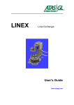
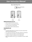
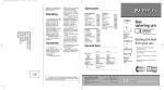
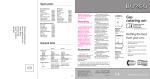
Quick Reference Guide
OPTIC 3 - PTV on
Shimadzu GC-2010 Gas Chromatograph
ATAS GL International B.V.
De Run 4441
5503 LS Veldhoven
The Netherlands
Tel:
+31 40 254 9531
Fax:
+31 40 254 9779
e-mail : [email protected]
Author: M. Kurano
Issue 1.0
Date
: 06-06-2008
Quality Control ATAS GL International
Quick Reference Guide – OPTIC 3-PTV on Shimadzu GC-2010
Doc. ID: SM-052
Pages: 11
Quick Reference Guide, OPTIC 3-PTV on GC-2010
This Quick Reference Guide is an addendum to the OPTIC 3-PTV Installation Guide
onto Shimadzu GC-2010 OEM (Doc. ID SM-042). Please, read both documents
attentively before installing the system.
This guide is made to understand:
1. How to operate GC/MS Solutions and Evolution Workstation software with OPTIC 3-PTV
Injection system installed on Shimadzu GC/MS QP2010.
2. How to use GC-2010 AFC unit for carrier gas control with OPTIC 3-PTV injector.
3. How to configure ‘dummy injector’ on GC/MS QP2010 system in case no Shimadzu injector
is installed.
4. How to create independent method using Evolution Workstation software in order to make
temperature program and set the control parameters for venting process if using Large
Volume Injection mode.
5. In case if OPTIC 3-PTV is combined with LINEX and CDC options, these options must be
controlled by CTC Analytics CycleComposer software running outside GC/MS Solution.
1. Installation of OPTIC 3-PTV
1.1 GC/MS QP2010 system
If OPTIC 3-PTV is the only injection port installed on the system, a ‘dummy’ SPL injector should
be installed using a ‘dummy’ connector for GC-2010 Injector Heater port. This ‘dummy’ connector
is a part of the Shimadzu 223-57164-91 AFC addition kit for GC- 2010. The ‘dummy’ SPL Injector
should be configured as it is shown in the example screens of GC-2010 in Fig. 1.
Figure 1. Configuration ‘dummy’ SPL injector.
ATAS GL International
Page 2 of 11
Quick Reference Guide, OPTIC 3-PTV on GC-2010
GC/MS Solutions Configuration
1.1.1 Instrument / System Configuration
This configuration is similar to standard SPL injector, since SPL is used as dummy injector for
OPTIC 3-PTV (see Fig. 2).
Figure 2. Instrument configuration
1.1.2 Instrument Parameters
Set the parameters as it is shown in Fig. 3.
Figure 3. Instrument Parameters Window.
ATAS GL International
Page 3 of 11
Quick Reference Guide, OPTIC 3-PTV on GC-2010
In order to avoid the temperature “ready check” for dummy injector (SPL1), SPL1 check box in the
Ready Check dialog window should be unchecked (Fig. 4).
Figure 4. Ready Check Dialog
2. Setting up OPTIC 3-PTV methods
2.1. Large Volume Injection Method
Set the parameters as it is shown in Fig. 5.
Figure 5. Setting up LVI Method
ATAS GL International
Page 4 of 11
Quick Reference Guide, OPTIC 3-PTV on GC-2010
Create a GC time program as it is shown in Fig. 6.
This time must be the same
as ‘sampling time’.
‘103’ means split valve closed.
‘-103’ means split valve opened.
Figure 6. GC Temperature Program
Large Volume Injection requires eliminating solvent before injector is heated up. This process
should programmed as a pre-running process (see example of the OPTIC 3 LVI method
programmed within Evolution Workstation in Fig. 7). However GC-2010 does not allow this kind of
pre-run programs.
LVI is simple: cold injection with solvent vent
Injector temp.
Column flow
Split flow
Cold splitless injection
Solvent vent
Figure 7. Example of LVI method within Evolution Workstation
ATAS GL International
Page 5 of 11
Quick Reference Guide, OPTIC 3-PTV on GC-2010
The LVI method for OPTIC 3-PTV should be made as a ‘Split method’ within GC Solutions
because the split valve must be opened during the solvent eliminating. During the method run,
after solvent is vented, OPTIC -3 sends start signal to GC-2010, the split valve is closed and GC
program is started.
NOTE:
If this method is cancelled during the GC run, the split valve cannot be initialized. In this
case, the split valve should be opened manually from the GC keypad.
2.2. LINEX Method
LINEX method is very complex because the injector pressure must be released before opening
the LINEX head. This is needed in order to avoid jumping up the liner out of injector. Also solid
material powder-like packing material or sample introduced into liner for the direct thermal
desorption can pusher out of the liner if pressure is not released. Fig. 8 below shows an exampled
of the LINEX method.
Figure 8. Example of LINEX method within GC Solutions.
ATAS GL International
Page 6 of 11
Quick Reference Guide, OPTIC 3-PTV on GC-2010
For the reasons mentioned above, Injection Mode should be set to Split, Flow Control Mode
should be set to Pressure and the initial pressure should be set to a minimum possible value
(12 kPa, for instance). At the same time, Total Flow should be set to a high value (more then 100
ml/min) in order to flush the interior of the injector after the LINEX head is closed. The “flush-time”
should be set through the Evolution Workstation using LINEX-TD or LINEX-DMI method. Initial
Septum Purge Flow should be set to ZERO because GC-2010 gives an error status if the LINEX
head is opened for long time. Since it is very difficult to control ZERO Septum Purge Flow, its
control parameters should be optimized (see Section 3).
When LINEX head is closed and the GC method is started, the injector pressure should be built up
to required pressure immediately. Purge Flow should also be built up to a value of 3 ml/min or so.
For this, Pressure program and Purge Flow program created be created according to the required
analytical parameters (see example in Fig. 9).
Figure 9. Example of a GC method
In case of Splitless method, the split valve must be closed immediately by GC program started at
the same moment as the Large Volume Injection method. Example of the program is shown in Fig.
10.
ATAS GL International
Page 7 of 11
Quick Reference Guide, OPTIC 3-PTV on GC-2010
This time must be same as
mean of ‘sampling time’.
‘103’ means split valve closed.
‘-103’ means split valve opened.
Figure 10. Example of GC Time Program
NOTE:
If this method is cancelled during the GC run, the split valve cannot be initialized. In this
case, the split valve should be opened manually from the GC keypad.
2.3. Settings for OPTIC 3 LINEX-TD Method
Example of the LINEX-TD method is shown in Fig. 11.
Figure 11. Example of LINEX-TD Method
ATAS GL International
Page 8 of 11
Quick Reference Guide, OPTIC 3-PTV on GC-2010
Please, note that Sample Sweep Time is the time needed to flush the injector after the LINEX
head is closed. When Sample Sweep Time is elapsed, injector and GC programs are started.
2.4. Settings for OPTIC 3 LINEX-DMI Method
In generally, DMI method is used for liquid injections and requires solvent elimination (similar to
Large Volume Injection method). The solvent elimination time should include the injector flush time
(see description for LINEX-TD method above). An example of the LINEX-DMI method is shown in
Fig. 12.
Using solvent monitor
Using Fixed Vent Time
Figure 12. Example of LINEX-DMI Method
3. Optimizing control parameters for purge flow
The optimization settings mentioned here only for the reference purposes. Please, consult the
service manual of the GC-2010 gas chromatograph or contact Shimadzu service department.
In case the septum purge flow should be set to zero, offset in the list the control parameters for
Purge Pressure should be optimized (see Fig. 13).
ATAS GL International
Page 9 of 11
Quick Reference Guide, OPTIC 3-PTV on GC-2010
Figure 13. Offset Optimization
If the value of the purge flow should be set to some value (3 ml/min, for example), gain in the list
the control parameters for Purge Pressure should be optimized (see Fig. 14).
Figure 13. Gain Optimization
ATAS GL International
Page 10 of 11
Quick Reference Guide, OPTIC 3-PTV on GC-2010
Even with above described optimization of the offset and gain, the error message can be delayed
for a maximum of 2 minutes. For this reason, in order to avoid the error message, the time
between opening and closing the LINEX head must be shorter then 2 minutes.
In some cases, 2 minutes is not long enough to perform all the required manipulation with the
sample. The only solution is then upgrading the OPTIC 3-PTV to OPTIC 3-S version. This version
contains a dedicated Electronic Gas Control designed to work with LINEX and CDC Station.
p/no H400062
4.
Upgrade kit OPTIC 3-PTV to OPTIC 3-S
Connecting LINEX Head to GC-2010 AFC
To install OPTIC 3-PTV with LINEX option, perform the following steps:
1.
Cut the ends of the PEEK lines connected to the LINEX Head as it is shown in Fig. 15.
2.
Connect the carrier line (blue marker) to AFC carrier line using the 1/8” union and the 1/8”
to1/16” reducing ferule.
Cut along line shown!
3.
Connect the second
line to the AFC purge flow line using the 1/8” union and 1/8” to 1/16”
reducing flow.
Please contact ATAS GL International BV if you have any questions.
[email protected]
http:// www.atasgl.com
ATAS GL International
Page 11 of 11