1
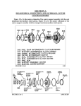
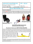
This is an old draft of some TH400 oil pump technical
information. Diagrams supplied by General Motors and ATSG
have been noted and are the property of the credited entity.
SECTION A
DISASSEMBLY AND INSPECTION OF THE OIL PUMP
Figure 10A-1 is the master schematic of the oil pump and related components.
FIGURE 10A-1
GM
Figure 10A-2 is the master schematic of the variable pitch oil pump cover and
related components.
FIGURE 10A-2
GM
With variable pitch models, remove the two stator solenoid attaching screws, the
stator solenoid, and the oil pump gasket. See Figure 10A-3.
FIGURE 10A-3
GM
Remove and discard the two oil seal rings (208) from the pump cover (202). 1964
to 1974 models were assembled with iron hook type rings. See Figure 10A-4. 1975
and up models received scarf cut Teflon type rings. Inspect the seal ring grooves for
signs of wear or damage. See Figure 10A-5. Ring groove width should measure @
approximately .095”. Ring groove depth should measure @ approximately .090”. If
the seal ring (s) is stuck or sticking in its groove, check for peening of the ring
groove, and replace the pump cover if necessary.
FIGURE 10A-4
PUMP COVER REAR
FIGURE 10A-5
GM
Remove the selective thrust washer (207) from the rear of the pump cover. See
Figure 10A-6. Inspect the washer for signs of wear or damage. Place the stator shaft
down thru a hole in the workbench and remove the five pump cover to pump body
bolts (203,204,205). See Figure 10A-7.
FIGURE 10A-6
FIGURE 10A-7
Remove the pump cover from the pump body (201). See Figure 10A-8. Use
Figure 10A-10 as a guide for the removal of the pressure regulator assembly
(211,212,213,214,215,216,217) from its bore in the pump cover. Mount the pump
cover assembly in a padded vice to support it during removal of the pressure
regulator assembly. Remove the retaining ring (211), the regulator boost valve
bushing (212), the regulator boost valve (213), and the pressure regulator spring
(214). See Figure 10A-9.
CAUTION: THE PRESSURE REGULATOR SPRING IS TIGHTLY
COMPRESSED AND WILL FORCE THE VALVE BUSHING OUT OF THE
BORE WHEN THE SNAP RING IS REMOVED IF THE BUSHING IS NOT
HELD SECURELY. DURING REMOVAL, KEEP PRESSURE ON THE
ASSEMBLY AND RELEASE IT SLOWLY OUT OF THE BORE.
FIGURE 10A-8
FIGURE 10A-9
GM
FIGURE 10A-10
GM
Remove the spring retainer washer (215), the spring spacer or spacers (216), and
the pressure regulator valve (217). See Figure 10A-11. Remove the straight pin
(219) and the valve bore plug (218). See Figure 10A-12. The bore plug exits from the
straight pin side of the bore.
FIGURE 10A-11
GM FIGURE 10A-12
GM
Inspect the lands of the pressure regulator valve for signs of scoring or wear. See
Figure 10A-13. Scoring may be a sign of excessive bore wear in the pump cover.
This will be checked shortly. Prepare the pressure regulator valve by chucking up
the outboard end of the valve in a cordless drill. See Figure 10A-14. The outboard
end of the valve does not operate in the valve bore and will not become damaged by
chucking it up in the drill. Lubricate the valve with penetrating oil, and polish the
valve lands for 5 to 10 seconds with a fine scotch pad. Wash the valve with clean
solvent and blow it dry with compressed air. The four lands on the pressure
regulator valve should measure in @ .624” + or - .0005”. See Figure 10A-15. Note
that there are first design and second design pressure regulator valves. Identify the
type of pressure regulator valve in use. The first design valve contains oil holes, an
orifice cup plug, and has no stem on the inboard end of the valve in comparison with
the second design “solid” valve. See Figure 10A-16. Do not interchange pressure
regulator valves without reviewing the information on Page ###.
FIGURE 10A-13
FIGURE 10A-14
FIGURE 10A-15
FIGURE 10A-16
Inspect and prepare the regulator boost valve in the same manner as the pressure
regulator valve. Inspect the bushing for signs of wear or damage. Fit the boost valve
into the bushing and verify smooth in and out operation. Use a micrometer to
measure the regulator boost valve lands. The small land on the boost valve should
measure in @ approximately .482”. The large land on the boost valve should
measure in @ approximately .604”. See Figures 10A-17 and 10A-18.
FIGURE 10A-17
FIGURE 10A-18
Use pin gages to measure the bushing bore diameters. The small bore should
measure in @ approximately .483”. See Figure 10A-19. The large bore should
measure in @ approximately .605”. See Figure 10A-20. The recommended boost
valve to bushing bore clearance is .0005” to .0012”. Subtract the measured boost
valve land diameter value from the measured bushing bore diameter value to arrive
at the boost valve to bushing bore clearance. Note that early models bushings are
aluminum, and are prone to increased wear.
FIGURE 10A-19
FIGURE 10A-20
Note that there are two extremely rare, smaller boost valve and bushing
combinations that were used in the TH400 transmission. When encountered, use the
same recommended clearance values stated. The measurements in this section are
for the most common valve and bushing combination.
The following information pertains to a bulletin regarding a mismachined
regulator boost valve bushing. The mismachined part was installed in 1984 model
year TH400 transmission between the Julian dates of 032 to 090. This machining
error can result in the small land of the boost valve falling out of its bore in the
bushing during transmission operation and sticking, resulting in high line pressure.
As a result of high line pressure, the forward clutch backing plate snap ring may
blow out of the forward clutch housing or the forward clutch piston may crack or
blow out the lip seals. A list of possible models affected by this issue is provided. If
the model being serviced cannot be identified by the serial number it is a good idea
to measure the bushing to eliminate any chance of reinstalling a defective
component.
Inspect the pressure regulator spring for signs of distortion and collapsed coils.
There are three versions of the production pressure regulator spring. Early models
were plain in color, and later models were color coded either blue or white. See
Figure 10A-21. Although the springs are all slightly different in appearance, they all
share the same rate at the installed height. If you have access to a spring tester you
can check the rate of the pressure regulator spring. At its installed height of 1.540”,
all production pressure regulator springs should weigh in @ 17.5 pounds. Inspection
of a production pressure regulator spring with the use of a specialty RIMAC spring
tester is shown in Figure 10A-22. Rates of 18 and up pounds indicate an aftermarket
pressure regulator spring has already been installed during prior service.
FIGURE 10A-21
FIGURE 10A-22
With variable pitch models, remove the retaining pin, stator valve spring, and
stator valve. See Figures 10A-23 and 10A-24. Inspect the spring for damage. Inspect
the lands of the stator valve for signs of scoring or wear. Light scoring can be
removed by lubricating the valve with penetrating oil and polishing the lands with a
fine Scotch pad. Inspect the bore for signs of wear or damage.
FIGURE 10A-23
GM FIGURE 10A-24
GM
Inspect the splines of the stator shaft for signs of wear or damage. The splines
should be square along their full length and free from scoring and galling. See
Figure 10A-25. Note that early models were not produced with induction hardened
splines and are prone to wear. Later models were produced with induction
hardened splines, eliminating wear, and are easily identified by being black in color.
If replacement is necessary, aftermarket stator shafts are available. Carefully
inspect the pump cover face for any signs of damage or scoring. See Figure 10A-26.
FIGURE 10A-25
FIGURE 10A-26
Use a whetstone and clean solvent to remove any burrs and create a flat,
conditioned sealing surface. Generate a nice cross hatch pattern over the entire face
of the pump cover. See Figure 10A-27. Place a precision straight edge across the
machined face of the pump cover. Try to install a .001” feeler gage between the
straight edge and the face to verify flatness. See Figure 10A-28. The feeler gage
should not fit. If the gage fits, the face is warped. This requires resurfacing or
replacement of the pump cover to maintain hydraulic integrity. Resurfacing is
shown on PAGE###. If you will be replacing the pump body, be sure to check
interchange information found on PAGE ###.
FIGURE 10A-27
FIGURE 10A-28
Most 1964 to 1967 models are equipt with a cooler by-pass system. This system
was intended to save the transmission internals from burn up due to lack of lube oil
in the event that the transmission cooler became clogged or severely restricted. The
resultant pressure increase in the system due to the blockage would open the cooler
by-pass valve assembly and route the hot oil exiting the torque converter destined
for the transmission cooler, directly to the transmissions lubrication circuit. By
bypassing the cooler, the internal components would remain in a bath of oil,
although hot oil, while the driver had enough time to make it to a service center for
further analysis. This of course was providing that the driver somehow realized the
transmission was overheating. Without an OEM transmission temperature gage
installed in the vehicle, this would prove impractical for the average motorist.
The sealing integrity of the by-pass valve can be checked by pouring a small
quantity of mineral spirits into the valve pocket and checking for excessive leakage.
Service parts are no longer readily available to repair a damaged by-pass assembly.
If the assembly is found to be damaged, replace the pump body or remove the bypass assembly and install a cup plug in its place to isolate the two circuits from one
another. If you have access to a replacement by-pass assembly, remove the seat by
threading it with a 3/8-16 tap. Install a 3/8-16 threaded adapter on to a slide
hammer and remove the seat, valve and spring. Install the replacement cooler bypass valve spring (large end first), the cooler by-pass valve, and the cooler by-pass
valve seat into the pump cover. Use a 5/8” diameter rod to drive the seat flush with
its bore in the pump body. The service manual procedure for by-pass assembly
replacement is shown in Figures 10A-29 and 10A-30.
FIGURE 10A-29
GM
FIGURE 10A-30
GM
Because most TH400 transmissions are used in high load applications, modifying
the pressure regulation system for increased or fixed line pressure is common
practice for increasing the torque capacity of the transmission. Because torque
converter charge pressure is a derivative of line pressure, increases in line pressure
result in increased converter charge pressure. If left as is, this increase in charge
pressure acting on the inside of the torque converter can push the torque converter
and flexplate forward into the engines crankshaft with enough force to quickly
destroy the crankshaft’s main thrust bearing. Placing a restriction in the converter
charge circuit eliminates the chances of this occurrence. The following modification
should be performed on all TH400 transmissions with increased or fixed line
pressure to reduce converter charge pressure to a safe level.
Locate the converter charge passage in the pump cover. See Figure 10A-31.
Using a 5/16-18 tap, thread the passage to a depth of approximately .250”. See
Figure 10A-32. Source a 5/16-18 X 3/16 brass set screw. See Figure 10A-33. Install
the set screw into the tapped hole. Be sure the set screw is installed to a depth below
the pump cover face. Drill a new converter charge orifice thru the set screw. See
Figure 10A-34. With production pressure regulator springs, drill orifice from .140”
to .157”. With aftermarket pressure regulator springs, drill the orifice from .120” to
.125”.
FIGURE 10A-31
FIGURE 10A-32
FIGURE 10A-33
FIGURE 10A-34
With variable pitch models, be sure to check the turbine shaft sealing ring bore
for wear or damage. It is located in the rear of the pump cover. See Figure 10A-35.
Inspect the front (220) and rear (206) stator shaft bushings for sign of wear, scoring,
pitting, or damage. Determine the stator shaft bushing to turbine shaft clearance.
Carefully set a bore gage to the inside diameter of each bushing. See Figures 10A-36
and 10A-37. Use a micrometer to measure the gage. See Figure 10A-38. The bushing
inside diameters should measure in @ .9990” to 1.0015”. If the bushings are not
within specifications, replace them.
In the absence of specialized measuring tools, another method can be used to
determine stator shaft bushing to turbine shaft clearance. Install the turbine shaft
(601) into the pump cover. Install the correct feeler gage that just fits in between the
bushing and the shaft to obtain the clearance. See Figure 10A-39. The recommended
clearance is .0005” to .0035”. If the clearance is not within specifications, replace the
bushing(s). Both bushings are the same. Replacement bushing is shown in Figure
10A-40. Before removing stator bushings with variable pitch models, note/record
the installed depth of the bushings as an assembly aid.
FIGURE 10A-35
FIGURE 10A-36
FIGURE 10A-37
FIGURE 10A-38
FIGURE 10A-39
FIGURE 10A-40
Carefully cut the bushings from the stator shaft. See Figures 10A-41 and 10A-42.
Use an arbor press and bushing driver to install the bushings. See Figure 10A-43.
Install the front bushing to a depth of .250” below flush, and the rear bushing to a
depth of .575” below flush. To verify the bushings have been installed properly, lube
the bushings and install the turbine shaft (601) into the pump cover and verify
smooth rotation. See Figure 10A-44.
FIGURE 10A-41
FIGURE 10A-42
FIGURE 10A-43
FIGURE 10A-44
The service manual procedure for bushing replacement is shown in Figure 10A45.
FIGURE 10A-45
GM
Note that some high performance torque converters use what is commonly
known as a “bushed turbine”. With this type of torque converter, the internal
turbine is supported by a bushing in the torque converter front cover instead of by
the input shaft and front stator shaft bushing. With this type of torque converter,
the removal of the front stator shaft bushing is required. If the front stator bushing
is not removed, the input shaft can be put into a bind during operation and can
result in component damage. When aftermarket torque converters are in use,
consult the manufacturer regarding their use of a bushed turbine.
Use Figure 10A-46 as a guide to install the pressure regulator assembly into its
bore in the pump cover.
FIGURE 10A-46
GM
Install the valve bore plug (218) and straight pin (219) into the pump cover. See
Figure 10A-47. Lubricate and install the pressure regulator valve (217) into the
pump cover (202). Install the pressure regulator spring spacer or spacers (216) and
pressure regulator spring retainer washer (215) over the pressure regulator valve.
See Figure 10A-48. Install the pressure regulator spring (214) into the bore and into
engagement with the tabs on the retainer washer. Install the pressure regulator
boost valve (213), stem end out, into the pressure regulator boost valve bushing
(212). Keep them together with assembly lube. Install the assembly into the bore
while at the same time compressing the spring enough so that the retaining ring
(211) will enter its groove at the end of the bore. See Figure 10A-49. On models with
the late pressure regulator valve, stroking of the pressure regulator valve can be
checked by applying compressed air to the balance hole as shown in Figure 10A-50.
FIGURE 10A-47
AMC/JEEP FIGURE 10A-48
FIGURE 10A-49
GM FIGURE 10A-50
GM
On variable pitch models, lubricate and install the stator valve and spring into
their bore in the pump cover and install the retaining pin. See Figures 10A-51 and
10A-52.
FIGURE 10A-51
GM FIGURE 10A-52
GM
Install the two oil seal rings (208) into their grooves on the rear of the pump
cover. See Figure 10A-53. If scarf cut Teflon type rings are being installed, verify
proper orientation of the ring end gaps as shown in Figure 10A-54.
FIGURE 10A-53
GM FIGURE 10A-54
GM
Disassembly of pump gears. Before removal, use a center punch or scribe to
make an identification mark on the front face of both the drive (209) and driven
gears (210) for proper orientation during reassembly. See Figure 10A-55. Remove
the pump drive and driven gears from the pump body (201). See Figure 10A-56.
Inspect the outside diameter, faces and gear teeth of both the drive and driven gears
for signs of scoring, wear, or damage. See Figure 10A-57. Inspect the drive gear
drive tangs and inside diameter of the drive gear for signs of scoring, wear or
damage. See Figure 10A-58. Improper torque converter to flexplate clearance will
usually result in damage to the driven gear at the interface between the drive tangs
and the torque converter pump drive hub.
FIGURE 10A-55
FIGURE 10A-56
FIGURE 10A-57
FIGURE 10A-58
GM
Prepare the faces of both gears with a whetstone and clean solvent. Using a
micrometer, measure and record the pump drive and driven gear thickness. See
Figures 10A-59 and 10A-60. There is no published specification for the overall
height of the gears; however production pump gears should measure in @ .7265” to
.7275”. If the gears come up undersize, replacement will depend on the value
obtained when measuring the pump body face to gear face clearance. Note that 1964
to 1966 fixed pitch model transmissions with a casting number of 1358649 use .625”
thick gears.
FIGURE 10A-59
FIGURE 10A-60
Inspect the pump gear pocket. Careful inspection of this area should not be
overlooked. Failure to identify wear will result in reduced oil pump efficiency.
Inspect the side wall of the gear pocket for any signs of scoring or abnormal wear.
See Figure 10A-61. If any wear can be felt with your fingernail, the body should be
replaced. Note that there is a tight tolerance between the outer diameter of the
driven gear and the side wall of the gear pocket. The side wall acts as a bearing
journal that supports the driven gear outside diameter on a fluid film during
operation. Inspect the pump gear pocket face for any signs of scoring or abnormal
wear. See Figure 10A-62. If any wear can be felt with your fingernail, the body
should be replaced.
FIGURE 10A-61
FIGURE 10A-62
Inspect the inside diameter of the crescent for any signs of scoring or abnormal
wear. See Figure 10A-63. If any wear can be felt with your fingernail, the body
should be replaced. Inspect the outside diameter of the crescent for any signs of
scoring or abnormal wear. See Figure 10A-64. If any wear can be felt with your
fingernail, the body should be replaced.
FIGURE 10A-63
FIGURE 10A-64
Inspect the five pump body threaded bolt holes for stripped or damaged threads
and repair if necessary. See Figure 10A-65. Carefully inspect the pump body face
for any signs of damage or nicks that can result in hydraulic cross leaks between oil
passages. See Figure 10A-66.
FIGURE 10A-65
FIGURE 10A-66
It is recommended to replace the pump body bushing (3) during the initial
overhaul, and then perform inspection during future service. Install the pump body
(201) over the torque converter pump drive hub. Install the correct feeler gage that
just fits in between the bushing and the hub to obtain the clearance. See Figure 10A67. The recommended clearance is .001” to .004”. If the clearance is not within
specifications, replace the bushing. It is recommended to remove the bushing with
the appropriate bushing driver. Always begin removal of the bushing at the seal end
of the pump body, working towards the pump gear pocket. See Figure 10A-68. If
you start removal at the pump gear pocket you will raise burrs that will create
problems during assembly. Figure 10A-69 shows the pump body bushing and the
pump body. Inspect the pump body bushing bore for any abnormal wear or
evidence that the bushing may have spun out in the bore. See Figure 10A-70. If
during removal, the bushing was loose in the bore, or the body shows signs of
bushing spin out, the body must be replaced.
FIGURE 10A-67
FIGURE 10A-69
FIGURE 10-68
GM FIGURE 10A-70
Inspect the bushing bore for the presence of burrs raised during bushing
removal. If any burrs are present, remove them with a small file. Using a deburring
tool, gently chamfer the front and rear entrances to the pump bushing bore. See
Figures 10A-71 and 10A-72.
FIGURE 10A-71
FIGURE 10A-72
Using a deburring tool, gently chamfer the front entrance to the driven gear
pocket. See Figure 10A-73. Use a whetstone and clean solvent to remove any burrs
and create a flat, conditioned sealing surface. See Figure 10A-74. Generate a nice
cross hatch pattern over the entire face of the pump body.
FIGURE 10A-73
FIGURE 10A-74
A lapping plate and the recommended lapping compound can also be used after
the whetstone if you have access to one. Rest the machined surface of the pump body
onto the plate. Using the weight of your hand, move the body in a figure eight
pattern and note the resistance to motion. See Figure 10A-75. As the surface
becomes conditioned, less resistance to attempted motion will be felt. After lapping,
thoroughly clean all remaining traces of lapping compound.
Place a precision straight edge across the machined face of the pump body. Try
to install a .001” feeler gage between the straight edge and the face to verify flatness.
See Figure 10A-76. The feeler gage should not fit. If the gage fits, the face is warped.
This requires resurfacing or replacement of the pump body to maintain hydraulic
integrity. Resurfacing is shown on PAGE###. If you will be replacing the pump
body, be sure to check interchange information found on PAGE ###.
FIGURE 10A-75
FIGURE 10A-76
Install the pump drive gear into the pump body. Install the correct feeler gage
that just fits in between the outside diameter of the gear and the side wall of the gear
pocket to obtain the clearance. See Figure 10A-77. The recommended clearance is
.002” to .006”. Note that clearance should be checked even with new aftermarket
gearsets, as most have been found to spec out @ .008” to .014”. Install the pump
driven gear into the pump body. Install the correct feeler gage that just fits in
between the inside diameter of the gear and the inside wall of the crescent to obtain
the clearance. See Figure 10A-78. The recommended clearance is .002” to .0075”.
FIGURE 10A-77
FIGURE 10A-78
Install the pump body bushing into the pump body. The replacement bushing is
shown in Figure 10A-79. Note that this bushing does not like to be installed with a
hammer and bushing driver. The use of an arbor press is recommended. Working
from the seal end of the pump body, install the bushing flush with the top of its bore.
See Figure 10A-80. To guarantee the bushing comes to a stop at the top of its bore
the use of a bushing installer with an outside diameter larger than the bushing may
be used.
FIGURE 10A-79
FIGURE 10A-80
To verify the bushing has been installed properly, lube the bushing and install
the pump body over the torque converter pump drive hub and verify smooth
rotation. See Figure 10A-81. Check the fit of the replacement front pump seal (2) on
the torque converter pump drive hub before installing it into the pump body. Verify
the presence of the garter spring behind the rear end of the seal lip of the front
pump seal. Pack the rear seal lip with grease prior to installation to avoid the garter
spring being ejected during seal installation. Using a suitable method, install a new
front pump seal into the pump body. See Figure 10A-82.
FIGURE 10A-81
FIGURE 10A-82
Determine pump body face to gear face clearance. See Figure 10A-83.
FIGURE 10A-83
GM
Note that the published clearance values have been revised several times
throughout the production of the GM TH400 transmission. Early General Motors
service manuals, depending on car maker, stated either a clearance of .0007” to
.0015” or .0008” to .0015”. This clearance was then revised to .0008” to .0035”,
before the final revision recommending .0007” to .0026”. From my perspective, the
preferred clearance is .0007” to .0015”. Extensive research has shown reduced
pump pressure and volume result below 2500 RPM when the oil pump is assembled
with clearances beyond .0015”. Install the gears into the pump body as shown in
Figure 10A-84.
FIGURE 10A-84
AMC/JEEP
Place a precision straight edge across the machined face of the pump body,
extending over the pump gears. Install the correct feeler gage that just fits in
between the straight edge and gear face to obtain the pump body face to gear face
clearance. See Figure 10A-85.
FIGURE 10A-85
GM
Clearance may also be obtained by measuring the gear pocket depth with a depth
gage and subtracting the gear thickness from it. See Figure 10A-86. If the clearance
is excessive, exchange the pump body or gear set.
FIGURE 10A-86
Once the recommended clearance has been established, remove the pump gears
from the pump body. To prevent pump damage from a dry start up, pack the pump
gear pocket with assembly lube. With the identification mark facing up, reinstall the
pump drive gear into the pump body. Reinstall the pump driven gear into the pump
body with the drive tangs facing up. See Figure 10A-87.
FIGURE 10A-87
GM
Position the assembled pump body with the bushing bore over a hole in the
workbench. See Figure 10A-88. Install the assembled pump cover over the pump
body and align the bolt holes. See Figure 10A-89.
FIGURE 10A-88
FIGURE 10A-89
Loosely install the five pump cover to pump body bolts (203,204,205). See Figure
10A-90.
FIGURE 10A-90
GM
On variable pitch models, the clip that retains the stator solenoid wire attaches to
the “C” bolt adjacent to the stator valve. A longer bolt is used at this location. See
Figure 10A-91.
FIGURE 10A-91
GM
To align the two pump sections, a pump alignment tool is used. Install and
tighten the pump alignment tool around the outside diameter of the pump assembly.
Be sure to align the thru holes in the body and cover for the pump to case bolts. This
can be done with a tapered punch. The early service manual version is shown in
Figure 10A-92. Note the stator solenoid wire retaining clip in the photo. A later
version is shown in Figure 10A-93.
FIGURE 10A-92
GM
FIGURE 10A-93
GM
In the absence of a pump alignment tool, the pump assembly may be installed
upside down in its bore in the transmission case to align the two sections as shown in
Figure 10A-94. Before installing the assembly into the case, be sure to remove any
surface rust from the outside diameter of the assembly with a fine grit emery cloth.
This will help to avoid the assembly becoming stuck in the transmission case.
Torque the five pump cover to pump body bolts to 200 inch pounds. See Figure
10A-95.
FIGURE 10A-94
GM FIGURE 10A-95
Place a TH400 torque converter flat on the bench with the pump drive hub
facing up and install the oil pump assembly. Verify free rotation of the pump gears.
See Figure 10A-96. On variable pitch models, install and align the pump to case
gasket to the rear of the pump cover. Fit the stator solenoid to the pump cover with
the attaching screws. See Figure 10A-97. Torque the attaching screws to 40 to 45
inch pounds. Attach the stator solenoid wire to the clip.
FIGURE 10A-96
FIGURE 10A-97
GM
SECTION 10 B
RESURFACING/MACHINING OF THE PUMP BODY AND PUMP
COVER
If during inspection the pump cover or pump body faces are found to be out of
specification, they can be resurfaced in a lathe to restore their original geometry.
These operations can also be performed on known flat components for increased
pump efficiency and improved sealing of the oil pump’s hydraulic circuits. When
fitting a JW Ultra Bellhousing to a TH400 transmission, the front face of the oil
pump should be machined parallel with the rear face of the bellhousing to provide a
true mounting surface. The recommended methods for performing these operations
are outlined in this section.
Using a manual lathe, the front end of the pump body is picked up with precision
soft jaws that attach to the inside diameter of the front pump bushing bore and
bank against its front face. The pump body is then swept with a dial indicator to
verify set up accuracy. The face of the pump body is then machined so that it is
parallel and perpendicular to the bushing bore. Typically this operation will remove
anywhere from .005” to .015” from the pump body face. See Figure 10B-1. Because
material has been removed from the face, the pump gear pocket depth dimension
will be reduced the same amount.
FIGURE 10B-1
This will require a set of undersize pump gears be installed to restore proper
pump body face to gear face clearence. To determine the required gearset thickness,
the pump gear pocket depth is measured and recorded. See Figure 10B-2. From this
dimension, the recommended pump body to gear clearance of .0007” to .0015” is
subtracted and you arrive at the required pump gear thickness. Undersize pump
gears were produced for the TH350 transmission and are readily available. .721”,
.723”, and .725” sets are available. If the available gear sets will not drop in, the
gear set may be surface ground to the proper dimension for the application. See
Figure 10B-3.
FIGURE 10B-2
If you will be installing a JW Ultra Bellhousing, perform this next operation.
Without removing the pump body from the jaws, bring the facing tool to the pump
to bellhousing mounting face and machine the mounting pad parallel to the pump
body face. See Figure 10B-4.
FIGURE 10B-4
Resurfacing the pump cover requires a different set up than the pump body. The
rear end of the pump cover is picked up with precision soft jaws that attach to the
forward clutch sealing ring boss outer diameter and bank against its face. At the
front end, the front stator tube bushing is removed, and the tube is fitted with a
precision plug and live center. The pump cover is then swept with a dial indicator to
verify set up accuracy. The face of the pump cover is then machined so that it is
parallel and perpendicular to the stator tube centerline. See Figure 10B-5. Without
removing the pump, the facing tool is brought to the rear side of the pump cover
and the gasket surface is machined. This ensures parallelism between the front and
rear faces, as well as the transmission case. See Figure 10B-6.
FIGURE 10B-5
FIGURE 10B-6
SECTION 10 C
IDENTIFICATION AND INTERCHANGE OF THE PUMP BODY
AND PUMP COVER
Identify the type of oil pump body and oil pump cover in use. Note that all 1965
to 1967 Buick and Oldsmobile models and some 1965 to 1967 Cadillac and Rolls
Royce models were produced with transmissions with the variable pitch feature.
These models utilized a variable pitch specific oil pump. The pump is easily
identified by the presence of a stator solenoid attached to the rear of the oil pump
cover, as well as a short set of stator shaft splines. See Figures 10C-1 and 10C-2.
FIGURE 10C-1
GM
FIGURE 10C-2
GM
The common casting number for the variable pitch pump cover is 8623761. See
Figure 10C-3. The common casting numbers for the variable pitch pump bodies are
8623056 and 8623759. See Figure 10C-4. Note that all variable pitch pump bodies
and pump covers are interchangeable.
FIGURE 10C-3
GM FIGURE 10C-4
GM
The first design early oil pump assembly was used in all 1964 to 1967 model year
fixed pitch TH400 transmissions. The common casting number for the first design
early oil pump cover is 8623073. See Figure 10C-5. The common casting numbers
for the first design early oil pump bodies are 1358649 and 8624068. See Figure 10C6. The 8623073 oil pump cover can be mated with any 1964 to 1993 oil pump body.
The 1358649 and 8624068 pump bodies can only be mated with the 8623073 pump
cover. The first design early oil pump assembly uses eight pump to case mounting
bolts.
The second design early oil pump assembly was used in all 1968 to 1970 model
year fixed pitch TH400 transmissions. The common casting numbers for the second
design early oil pump covers are 8626174 or 8626176. See Figure 10C-7. The
common casting number for the second design early oil pump body is 8626121. See
Figure 10C-8. The 8626174 or 8626176 oil pump covers can be mated with any 1968
to 1993 oil pump body. The 8626121 pump body can be mated with any 1964 to 1993
pump cover. The second design early oil pump assembly uses eight pump to case
mounting bolts.
FIGURE 10C-7
GM FIGURE 10C-8
GM
Close inspection of the second design early oil pump body shows that the
assembly was carried over from the GM JETAWAY for use in the GM TH400.
Several oil passages remained in the casting, although not used with the TH400. The
use of the TH400 specific pump cover eliminated any issues encountered with the
left over passages. The JETAWAY oil pump body is shown in Figure 10C-9 and the
TH400 8626121 casting in Figure 10C-10.
FIGURE 10C-9
GM FIGURE 10C-10
GM
The late oil pump assembly was used in all 1971 to 1993 model year fixed pitch
TH400 transmissions and featured all new castings. See Figures 10C-11 and 10C-12.
The common casting numbers for the late oil pump covers are 8626896 and
8627000. The common casting numbers for the late oil pump body is 8626895. The
8626896 and 8627000 oil pump covers can be mated with any 1968 to 1993 oil pump
body. The 8626895 pump body can be mated with any 1968 to 1993 pump cover.
The 1971 to 1972 late oil pump assembly uses eight pump to case mounting bolts,
and 1973 to 1993 models use six. Most 1973 and up late pump covers used stator
shafts with heat treated stator shaft splines.
FIGURE 10C-11
GM FIGURE 10C-12
GM
The major change here was the removal of the pressure regulator valve balance
hole from the regulator valve and its relocation to the pump cover casting. It is
identified as the pressure regulator feed hole in Figure 10C-13. 1964 to 1970 models
did not use this hole in the casting, as it was an integral part of the early pressure
regulator valve. See Figure 10C-14.
FIGURE 10C-13
GM FIGURE 10C-14
GM
This permitted the use of a solid pressure regulator valve. This was probably
done as a cost saving measure, as it eliminated the drilling and plugging operations
performed to the regulator valve during the manufacturing process. See Figure
10C-15.
FIGURE 10C-15
GM
Never install the late solid pressure regulator valve in any 1964 to 1970 oil pump
cover. The absence of the balance hole removes the systems self regulating feature
and will instantly produce excessive line pressure resulting in immediate component
failure. The early orifice plug pressure regulator valve can be installed in all pump
covers.
For ease of identification, the 1971 to 1993 late oil pump cover, with the added
pressure regulator feed hole, features a squared off pressure regulator valve boss at
the boost bushing end. See Figure 10C-16. When replacing or servicing the TH400
oil pump, the absence of the squared off pressure regulator valve boss in the pump
cover casting should instantly alert you to verify the type of pressure regulator valve
in use.
FIGURE 10C-16
GM
Figure 10C-17 is used to quickly verify the compatibility of a specific pump body
and pump cover combination when interchanging components.
FIGURE 10C-17
GM
SECTION 10 E
OIL PUMP DIAGRAMS
Oil Pump Exploded View
FIGURE 10E-1
GM
Pump Cover Attaching Screws
FIGURE 10E-2
GM
Pump Cover to Cases Passages
FIGURE 10E-3
GM
Variable Pitch Pump Body and Pump Cover
FIGURE 10E-4
ATSG
Early Pump Body and Pump Cover
FIGURE 10E-5
ATSG
Late Pump Body and Pump Cover
FIGURE 10E-6
ATSG