1
Pump Installation and Service Manual
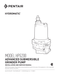
HPGB750/1000/1500
Submersible Grinder Pumps
NOTE! To the installer: Please make sure you provide
this manual to the owner of the pumping equpment or to
the responsible party who maintains the system.
TM
1
23833A617
17. Do not exceed manufacturers recommendation for
maximum performance, as this could cause the
motor to overheat.
18. Secure the pump in its operating position so it can
not tip over, fall or slide.
19. Keep hands and feet away from impeller when
power is connected.
20. Submersible grinder pumps are not approved for
use in swimming pools, recreational water installations, decorative fountains or any installation where
human contact with the pumped fluid is common.
21. Do not operate pump without safety devices in
place.
CAUTION!
Read these safety warnings first before
installing, servicing, or operating any
pump.
GENERAL
1. Most accidents can be avoided by using
COMMON SENSE.
2. Read the operation and maintenance instruction
manual supplied with the pump.
3. Do not wear loose clothing that can become
entangled in the impeller or other moving parts.
4. This pump is designed to handle materials which
could cause illness or disease through direct
exposure.
IMPORTANT! Hydromatic is not responsible for losses,
injury or death resulting from a failure to observe these
safety precautions, misuse or abuse of pumps or
equipment.
Wear adequate protective clothing when working
on the pump or piping.
ELECTRICAL
GENERAL INFORMATION:
WARNING: Only qualified persons shall conduct
services and installations of this pump. The
pump must be wired by a qualified electrician,
using an approved starter box and switching
device.
5. To reduce the risk of electrical shock, pump must
be properly grounded in accordance with the
National Electric Code and all applicable state
and local codes and ordinances.
6. To reduce risk of electrical shock, disconnect the
pump from the power source before handling or
servicing.
7. Any wiring to be done on pumps should be done
by a qualified electrician.
8 Never operate a pump with a power cord that has
frayed or brittle insulation.
9. Never let cords or plugs lay in water.
10. Never handle connected power cords with wet
hands.
Pump Models: These instructions cover the installation and service of the Hydromatic HPGB750/1000/
1500 submersible grinder pumps.
Motor HP & Voltages: These submersible grinder
pumps are offered in three phase, 7½, 10 and 15 HP.
Voltages will vary according to the application and can
be seen in the tables in this manual. Three phase
stators are available with dual voltage configurations
that will allow either 230V or 460V internal connection.
Electrical Controls: All of these pump models must
be used with a control panel. Hydromatic built control
panels are designed to supply the correct electrical
controls, motor starting equipment and include the
circuitry for moisture and heat sensors. It is recommended that a Hydromatic built control panel be used
so that all warranties apply.
General Construction: A cross sectional view of the
internal workings of the pumps can be seen on page 6.
The motor chamber and seal chamber are filled with a
high dielectric type oil for improved lubrication and heat
transfer of the bearings and motor. Since the bearings
have been designed for 50,000 hours of life, the oil
should never require replacement under normal operating conditions. An air space above the oil level in both
the seal and motor chambers is provided to allow for
the expansion of the oil when at operating temperature.
The power and control lines are sealed and strain
relieved on the outside entrance with a standard cord
grip, and internally through the use of a dielectric
potting resin surrounding the electrical wires. Internal
connection wiring diagrams are shown in Figure 2. All
of the pump fasteners and shafts are mad from corrosion resistant stainless steel, while the pump castings
are made of ASTM A-48 Class 30 cast iron, and the
multi-vane vortex impellers are made from ductile iron.
PUMPS
11. Pump builds up heat and pressure during operation, allow time for pump to cool before handling
or servicing.
12. Only qualified personnel should install, operate or
repair pump.
13. Keep clear of suction and discharge openings.
DO NOT insert fingers in pump with power
connected.
14. Do not pump hazardous material not recommended for pump (flammable, caustic, etc.).
15. Make sure lifting handles are securely fastened
each time before lifting.
16. Do not lift pump by the power cord.
23833A617
2
General Installation: Various configurations and
methods of plumbing this series of non-clog pumps
may be used; however, for ease of installation and
service a Hydromatic rail lift-out system is
recommended.
The resistance across the moisture sensing (seal
failure) probes, should be checked after a seal leak
warning light has lit. This can be done by disconnecting the red and orange control wires from the control
panel, and measuring the resistance with an ohm
meter between the wires. For a standard, nonexplosion proof pump the reading should be 100,000
ohms or greater, and for an explosion-proof pump the
reading should be above 30,000 ohms. If the measured values are below those indicated above, the
pump may have a lower seal failure and require
service.
Service: These pumps are to be used for handling
sewage, wastewater and storm water only. Do not
use in hazardous locations. These motors must be
repaired and serviced only at Hydromatic Authorized
Service Centers or at the Hydromatic Factory. Any
unauthorized field repair voids warranty.
Note: Hydromatic built control panels supply the
correct circuitry for moisture and heat sensor connections. Failure to install the correct circuitry with
proper connection would negate warranty.
See Figure 3.
CAUTION: After the pump is installed and sewage
has entered the basin there is “Danger”. Sewage
water gives off methane and hydrogen sulfide
gases, which are poisonous. Never enter a
wetwell unless the cover is open for a sufficient
period of time to allow fresh air into the basin. It
is recommended that a man in the basin has a
harness on with a rope to the surface, so that he
can be pulled out in case of asphyxiation. It is for
this reason that Hydromatic recommends using
the rail lift-out system so that no service is
required inside the basin.
Motor Power Cord, Control Cord and Cord Cap
Assembly: Each motor power cord has 4 conductors
- white, black, red and green. For a three phase
motor the red, black and white conductors connect to
the three line leads, and the green is connected to a
good ground. Interchanging any two line leads will
reverse the rotation of the motor.
Motor: Each motor is provided with heat sensor
thermostats attached directly to the motor windings.
The thermostats open if the motor windings see
excessive heat and, in turn, open the motor contactor
in the control panel, breaking the power to the pump.
Note: Rotation should be clockwise when observed
from the top of the pump. This can be checked by
noting which direction the pump torques upon initial
starting. A properly rotating pump will torque counterclockwise upon start.
When the motor is stopped due to an overheat
condition, it will not start until the motor has cooled
and the heat sensor reset button is manually pushed
on the front of the Hydromatic control panel. This
circuitry is provided in the Hydromatic control panel
designs.
The control cable has 5 conductors - black, white,
red, orange and green. White and black connect to
the heat sensor terminals in the control panels; red
and orange connect to the seal failure terminals in the
control panel; and the green connects to the ground in
the control panel.
The HPGB750/1000/1500 pumps are equipped with
internal thermostats. To meet Class H heat rise of
356°F (180°C).
The cord cap is epoxy potted. The cord cap provides
for a sealed wire connection with terminals so that
connections can be made without breaking the motor
seal. This allows the cord cap, with cords, to be
removed from the motor. With this arrangement, the
cords can be permanently installed in a sealed fitting
in the sump. The control and power cables cannot
be spliced! When the pump is removed for service,
the cord cap can stay and be reinstalled when pump
is returned.
Note: Failure to use proper circuitry and to connect
the motor overheat protection in the control panel
would negate all warranties.
Motor Seal Failure Warning: The seal chamber is
oil filled and provided with moisture sensing probes to
detect water leakage through the lower shaft seal.
The probes can also detect moisture present in the
upper motor housing.
Note: Each cable has a green ground wire and must
be properly grounded per the National Electric Code
and local codes.
The presence of water energizes a red seal leak
warning light at the control panel. This is a warning
light only, and does not stop the motor. It indicates a
leak has occurred and the pump must be repaired.
Normally, this indicates the outboard seal has leaked.
Allowing the unit to operate too long after the warning
could cause upper seal leakage along with motor
failure.
3
23833A617
REPLACING GRINDER IMPELLER AND
GRINDER SHREDDING RING
Electrical Motor Controls: All electrical controls and
motor starting equipment should be as specified in
these instructions. Consult factory for any acceptable alternates.
This is the only disassembly operation allowed in the
field. All other repairs must be done at the factory or
at an authorized service station.
Level Sensing Controls: The float level controls
maintain the basin sewage water level by controlling
pump turn-on and turn-off levels.
STANDARD TOOLS REQUIRED:
1. All had socket set.
2. Standard socket wrench set
3. Set of open end wrenches.
4. Plastic hammer.
5. Vise grip pliers.
6. Large screwdriver 5/8” wide blade; heavy handle.
7. Wire brush.
8. Three cornered file.
9. Several smaller screwdrivers.
1. The lower turn-off control should be set so that the
pump stops with the water covering the entire
motor housing. Consult the factory for any
settings below this point.
2. The upper turn-on control should be set above the
lower turn-off control. The exact height between
the two controls is determined by the number of
pump starts desired and the depth of the basin. A
maximum of 10 starts per hour should not be
exceeded.
IMPORTANT - Pump should be thoroughly cleaned of
trash and deposits before starting disassembly
operations.
3. The override control is set at a specified height
above the upper turn-on control.
CAUTION - DISCONNECT ALL POWER AND
CONTROL WIRES TO MOTOR AT CONTROL
PANEL BEFORE STARTING DISASSEMBLY
OPERATIONS. NEVER RELY ON OPENING
CIRCUIT BREAKER ONLY.
4. The alarm control is set about 6” to 12” above the
override control.
5. No control should be set above the inlet invert.
DISASSEMBLY OF SHREDDING RING
AND IMPELLER
Electrical Connections: All electrical wiring must be
in accordance with local code and only qualified
electricians should make the installations. Complete
wiring diagrams are included for use in making the
installation. All wires should be checked for shorts to
ground with an ohmmeter or megger after the connections are made. This is important, as one grounded
wire can cause failure of the pump, control panel or
personal injury.
1. Remove screws from holding ring and remove
ring.
2. Use two screwdrivers, one each on opposite side
of ring and pry shredding ring out. Remove
shredding ring.
3. Hold impeller by prying against impeller cutting
bar and remove cap screw from end of shaft.
Pump: The fluid end of the pump is field serviceable
and can be disassembled in case of wear, damage,
plugging or outboard seal failure. The following will
describe the disassembly and reassembly process.
4. Use large screwdriver in slot in end of shaft and
bump on cutter vane with plastic hammer. Bump
in counterclockwise direction as thread is right
hand. It may take several bumps to loosen
impeller.
If impeller cannot be loosened it will be necessary to take unit to service station for service.
DON’T CONTINUE TO POUND ON IMPELLER
AS IMPELLER AND SHAFT CAN BE
DAMAGED.
23833A617
4
5. If impeller comes off easily clean up and replace
if worn.
6. Be sure pump impeller has not loosened when
grinder impeller is removed. This can be checked
on reassembly of grinder impeller and shredding
ring. Tips of impeller cutter vanes should extend
about 1/8” below bottom of shredding ring. If
more than 1/8” extends below ring it means pump
impeller has loosened. See sectional drawing
Fig. 1 or Fig. 2.
Remove grinder impeller and ring as described
above and remove bolts from pump case and
remove case. Use back off screws in motor
mounting plate to pry loose from pump case.
7. After case is removed wrap emery paper around
shaft and hold with vise grip pliers. Use cloth on
impeller and screw up against shoulder. Now
pump can be reassembled.
8. Clean all threads with wire brush and file smooth
any threads that may be nicked.
9. Use Never-Seeze or other graphite compound on
threads before replacing grinder impeller.
10. Be sure cap screw in bottom of shaft is tight.
Hold impeller with screwdriver between cutter bar
and teeth of shredding ring while tightening cap
screw.
11. Be sure impeller turns free by hand after reassembly. Some drag will occur due to seals but
there should be no binding or tight spots when
turning the grinder impeller.
12. ALWAYS use a rag on the impellers when turning
to prevent cutting hands on the sharp corners of
shredding ring.
5
23833A617
23833A617
6
Parts List
REF.
NO.
1
2
3
4
5
6
7
8
9
10
11
12
13
14
15
16
17
18
19
20
21
22
23
24
25
26
26A
27
28
29
30
31
32
33
34
35
36
37
38
Catalog No.
HPGB750M6-2
HPGB750M3-2
HPGB750M4-2
HPGB750M5-2
HPGB1000M6-2
HPGB1000M3-2
HPGB1000M4-2
HPGB1000M5-2
HPGB1500M6-2
HPGB1500M3-2
HPGB1500M4-2
HPGB1500M5-2
DESCRIPTION
Cord cap assembly
O-Ring
HHCS 1/2"-13 UNC x 1-3/4"
Upper bearing cap
Load Spring
Ball bearing, upper
Rotor/shaft assembly
Shaft (only)
Motor housing
Stator
Ball bearing, lower
HHCS 1/2"-13 UNC x 2-1/2"
O-Ring
Seal housing, upper
Shaft seal
Retaining ring
HHCS 1/2"-13 UNC x 1-1/2"
Seal housing, lower
Gasket
Impeller
Impeller washer
Volute
Shredder ring clamp
Shredder ring
Grinder impeller
Impeller retainer
Impeller retaining screw
Sealant
HHCS 3/8"-16 UNC x 1"
Key
Seal leak probe
Machine screw #6
Electrode wire
Resistor (X-PRF only)
Oil
Tube - plastic
O-Ring
Machine screw 5/16"-18 UNC x 1"
Lock washer
Washer
Machine screw 1/4"-20 UNC x 1/2"
Pipe-plug 1/4" NPT (not shown)
Rotor/Shaft
Assembly
27098D100
27098D100
27098D100
27098D100
27098D100
27098D100
27098D100
27098D100
27098D100
27098D100
27098D100
27098D100
Stator
141452031
141450031
141450031
141456031
141452031
141450031
141450031
141456031
141462031
141460031
141460031
141466031
7
Part No.
see chart
05876A119
19103A045
22873C000
191331A007
08565A032
see chart
27097D100
22874D000
see chart
08565A026
19103A048
05876A121
22882D010
22883A000
12558A017
19103A043
25991D010
05231A084
see chart
27099A000
27095E000
22587C000
22586B010
22584C000
22585A000
07597A021
14550A009
19101A010
05818A067
25343A100
05454A025
22578A100
22912A000
11009A008K
10649A116
05876A120
07597A017
06107A016
05030A241
05028A002
05022A092
Cord Cap Ass'y
(25')
22872C010
22872C010
22872C010
22872C011
22872C012
22872C012
22872C010
22872C010
22872C012
22872C012
22872C010
22872C010
NO.
REQ'D
1
1
4
1
2
1
1
1
1
1
4
2
1
2
1
8
1
1
1
1
1
1
1
1
1
1
1
1
1
2
2
2
1
1.8 gal
2
1
2
1
1
1
2
Housing w/
Stator
22874D357K
22874D362K
22874D362K
22874D367K
22874D358K
22874D363K
22874D363K
22874D368K
22874D372K
22874D377K
22874D377K
22874D382K
Impeller
27096D002
27096D001
27096D000
23833A617
MOTOR INTERNAL CONNECTION DIAGRAMS
23833A617
8
WIRING DIAGRAM: 200, 230 & 460V, 3ø, SIMPLEX, 7½, 10, & 15 HP
9
23833A617
PUMP PERFORMANCE
PUMP PERFORMANCE
SUBMERSIBLE GRINDER PUMPS
MODELS: HPGB750/1000/1500
SPEED:
HPGB1
HPGB1
3450 RPM
500 15
HP
000 10
HP
HPGB7
50 7-1
/2 HP
Available Models
Standard
HPGB750M6-2
HPGB750M3-2
HPGB750M4-2
HPGB750M5-2
HPGB1000M6-2
HPGB1000M3-2
HPGB1000M4-2
HPGB1000M5-2
HPGB1500M6-2
HPGB1500M3-2
HPGB1500M4-2
HPGB1500M5-2
23833A617
HP
7-1/2
7-1/2
7-1/2
7-1/2
10
10
10
10
15
15
15
15
Volts
200
230
460
575
200
230
460
575
200
230
460
575
Phase
3
3
3
3
3
3
3
3
3
3
3
3
Hertz
60
60
60
60
60
60
60
60
60
60
60
60
Start
Amps
192.7
167.6
83.8
67.0
192.7
167.6
83.8
67.0
256.2
222.8
111.4
89.1
Motor Electrical Data
Service
Service
Run
Factor
Factor
Amps
Amps Run KW
KW
39.8
47.8
8.1
11.9
34.6
41.5
8.1
11.9
17.3
20.8
8.1
11.9
13.9
16.7
8.1
11.9
55.7
66.8
10.2
15.5
48.4
58.1
10.2
15.5
24.2
29.0
10.2
15.5
19.4
23.3
10.2
15.5
68.4
82.1
17.6
19.7
59.5
71.4
17.6
19.7
29.8
35.8
17.6
19.7
23.8
28.6
17.6
19.7
10
Start
KVA
66.8
66.8
66.8
66.8
66.8
66.8
66.8
66.8
88.7
88.7
88.7
88.7
Run
KVA
13.8
13.8
13.8
13.8
19.3
19.3
19.3
19.3
23.7
23.7
23.7
23.7
NEC
Code
Letter
K
K
K
K
H
H
H
H
G
G
G
G
Service
Factor
1.2
1.2
1.2
1.2
1.2
1.2
1.2
1.2
1.2
1.2
1.2
1.2
PUMP DIMENSIONS
[dimensions in mm]
12”
[306]
Flange drilled for
21/2” std. pipe flange
143/8”
[366]
343/16”
[868]
21/2” Dia.
7”
[178]
83/16”
[209]
11
23833A617
CHECK LIST IF PUMP DOES NOT
OPERATE PROPERLY
Readings should be taken with line leads disconnected from the control panel.
CHECKING FOR MOISTURE IN MOTOR - Use
ohmmeter or a megger and set on highest scale.
Readings on the large power cord between any of the
conductors red, black, or white to green conductor or
to the motor housing should be greater than
1,000,000 ohms (1 megaohm). Motor probably will
run with a lower reading, but if pump is out of service
and reading is below 1,000,000 ohms (1 megaohm),
the motor housing and stator should be removed and
baked in a drying oven at 220°F. This service work
should only be done at an authorized service station.
RESISTANCE OF WINDINGS - Every motor winding
has a fixed resistance and winding must check close
to the values given below to operate properly. Verification of the proper wiring of a dual voltage motor can
also be checked by measuring the motor winding
resistance. See the motor electrical data chart. Use
an ohmmeter and set to the one ohm scale. Read the
resistance with the motor leads disconnected from
the pump control panel.
TROUBLE CHECK LIST
Troubles listed are generally caused by the pump. Other trouble can occur from faulty control box operation.
CONDITION
PROBABLE CAUSE
Pump runs but does not pump liquid from basin
1. Pump impeller may be air locked, this occasionally occurs on a new installation. Start and stop
pump several times to purge air.
2. Run additional water into basin so that pump will
be submerged deeper to clear air.
3. If pump is three phase, rotation may be wrong.
See instructions for checking proper rotation.
4. If air does not clear it may be necessary to lift
pump out of sealing elbow and start motor to allow
pump to pump for a few seconds.
Air vent hole is provided in pump case, so some
water will flow from this hole when pump is
operating. If vent hole gets clogged clean out.
5. If pump has been installed for some time and does
not pump, it may be clogged at grinder inlet.
6. Discharge gate valve may be closed.
7. Discharge check valve may be clogged or have a
broken clapper.
8. Discharge head may be too high. Check elevation.
Maximum pump head at zero flow is shown on
pump curve sheet.
9. If above checks do not locate trouble, motor rotor
may be loose on shaft which allows motor to run
but will not turn impeller or only at low RPM.
Red light comes on at control box.
23833A617
This indicates some water has leaked past the
lower seal and has entered the seal chamber and
made contact with the electrode probe. Pump
must be removed from basin within approximately
two (2) weeks fro replacement of lower seal. This
preventative repair will save an expensive motor.
12
Overload trips at control box and alarm buzzer
or flashing red light comes on due to high water
level in basin.
1. Push in on red reset button to reset overload.
If overload trips again after short run, pump has
some damage and must be removed from basin
for checking.
2. Trouble may be from clogged grinder causing
motor to overload or could be from failed motor.
3. Trouble may be from faulty component in control
box. Always check control box before removing
pump.
Yellow run light stays on continuously.
1. Indicates H-O-A switch may be in the hand
position.
2. Level control switch may have failed causing
pump to continue to operate when water is below
lower weight, o lower weight may have dropped
off.
3. Grinder assembly may be partially clogged
causing pump to operate at very reduced capacity.
4. Gate valve or check valve may be clogged
causing low pump flow.
5. Pump may be air logged.
Circuit breaker trips.
1. Reset breaker by pushing clear down on handle
then back to on position. If breaker trips again in
few seconds it indicates excessive load probably
caused by a short in the motor or control box.
Check out instructions given with control box
before pulling pump.
2. If this condition happens after an electrical storm,
motor or control box may be damaged by lightning.
3. Resistance reading of the motor with lead wires
disconnected from the control box can determine if
trouble is in motor or control box.
Pump is noisy and pump rate is low.
1. Grinder assembly may be partially clogged with
some foreign objects causing noise and overload
on the motor.
2. Grinder impeller may be rubbing on grinder ring
due to bent shaft or misalignment.
Grease and solids have accumulated around
pump and will not pump out of basin.
1. Lower weight of level switch may be set too high.
Set bottom of lower weight even with bottom of
inlet flange to grinder.
2. Run pump on hand operation for several minutes
with small amount of water running into basin to
clean out solids and grease. This allows pump to
break suction and surge which will break up the
solids. If level switch lower weight is set properly
this condition generally will not occur.
3. Trash may have accumulated around lower weight
causing pump to turn off too soon. Clean trash
from weight and suspension cable.
13
23833A617
Pump
Notes
______________________________________________
______________________________________________
______________________________________________
______________________________________________
______________________________________________
______________________________________________
______________________________________________
______________________________________________
______________________________________________
______________________________________________
______________________________________________
______________________________________________
______________________________________________
______________________________________________
______________________________________________
______________________________________________
______________________________________________
______________________________________________
______________________________________________
______________________________________________
______________________________________________
______________________________________________
______________________________________________
______________________________________________
23833A617 1/07
14
Pump
Notes
______________________________________________
______________________________________________
______________________________________________
______________________________________________
______________________________________________
______________________________________________
______________________________________________
______________________________________________
______________________________________________
______________________________________________
______________________________________________
______________________________________________
______________________________________________
______________________________________________
______________________________________________
______________________________________________
______________________________________________
______________________________________________
______________________________________________
______________________________________________
______________________________________________
______________________________________________
______________________________________________
______________________________________________
15
23833A617
LIMITED PRODUCT WARRANTY
HYDROMATIC warrants that its products are free from defects in material and workmanship for a period of
twelve (12) months from the date of purchase or eighteen (18) months from the date of manufacture, whichever
occurs first.
®
During the warranty period and subject to the conditions hereinafter set forth, HYDROMATIC, will repair or
replace to the original user or consumer parts which prove defective due to defective materials or workmanship
of HYDROMATIC. Contact the nearest authorized HYDROMATIC distributor, HYDROMATIC authorized
service center or HYDROMATIC for warranty service. At all times, HYDROMATIC shall have and possess
the sole right and option to determine whether to repair or replace defective equipment, parts or components.
Start up reports and electrical system schematics may be required to support warranty claims. Warranty is
effective only if HYDROMATIC supplied or authorized control panels are used, where applicable. All dual
seal pumps must have seal failure and heat sensors attached, functional and monitored for the warranty to be
in effect. If a seal failure should occur, HYDROMATIC will only cover the lower seal and labor thereof. If the
heat sensor and seal fail sensor is not attached and functional, the warranty is void.
LABOR, ETC. COSTS: HYDROMATIC shall in NO EVENT be responsible or liable for the cost of field labor,
removal and/or reinstallation charges of any HYDROMATIC product, part or component thereof, or the
expense of freight.
THIS WARRANTY WILL NOT APPLY: (a) to defects or malfunctions resulting from failure to properly install,
operate or maintain the unit in accordance with printed instructions provided; (b) to failures resulting from
abuse, accident or negligence; (c) to normal maintenance services and the parts used in connection with such
service; (d) to units which are not installed in accordance with applicable local codes, ordinances and good
trade practices; or (e) if the unit is moved from its original installation location; (f) unit is used for purposes
other than for what it was designed and manufactured; (g) to any unit which has been repaired or altered by
anyone other than HYDROMATIC, a HYDROMATIC distributor or a HYDROMATIC authorized service
center and (h) to any unit which has been repaired using non factory specified parts/OEM parts.
RETURN OR REPLACED COMPONENTS: any item to be replaced under this Warranty must be returned
to HYDROMATIC in Ashland, Ohio, or such other place as HYDROMATIC may designate, freight prepaid.
PRODUCT IMPROVEMENTS: HYDROMATIC reserves the right to change or improve its products or any
portions thereof without being obligated to provide such a change or improvement for units sold and/or
shipped prior to such a change or improvement.
WARRANTY EXCLUSIONS: HYDROMATIC MAKES NO EXPRESS OR IMPLIED WARRANTIES WHICH
EXTEND BEYOND THE DESCRIPTION ON THE FACE HEREOF. HYDROMATIC SPECIFICALLY DISCLAIMS
THE IMPLIED WARRANTIES OF MERCHANTABILITY AND FITNESS FOR ANY PARTICULAR PURPOSE.
Some states do not permit some or all of the above warranty limitations and, therefore, such limitations may
not apply to you. No warranties or representations at any time made by any representatives of
HYDROMATIC shall vary or expand the provision hereof.
LIABILITY LIMITATION: IN NO EVENT SHALL HYDROMATIC BE LIABLE OR RESPONSIBLE FOR
CONSEQUENTIAL, INCIDENTAL OR SPECIAL DAMAGES RESULTING FROM OR RELATED IN ANY MANNER
TO ANY HYDROMATIC PRODUCT OR PARTS THEREOF. PERSONAL INJURY AND/OR PROPERTY DAMAGE
MAY RESULT FROM IMPROPER INSTALLATION. HYDROMATIC DISCLAIMS ALL LIABILITY, INCLUDING
LIABILITY UNDER THIS WARRANTY, FOR IMPROPER INSTALLATION — HYDROMATIC RECOMMENDS
INSTALLATION BY PROFESSIONALS.
Some states do not allow the exclusion or limitation of incidental or consequential damages, so the above
limitation or exclusion may not apply to you.
This Warranty gives you specific legal rights and you may also have other rights which vary from state to state.
In the absence of suitable proof of this purchase date, the effective date of this warranty will be based upon
the date of manufacture.
– Your Authorized Local Distributor –
USA
740 East 9th Street, Ashland, Ohio 44805
Tel: 419-289-3042 Fax: 419-281-4087
www.hydromatic.com
© 2008 Hydromatic Ashland, Ohio. All Rights Reserved.
®
CANADA
269 Trillium Drive, Kitchener, Ontario, Canada N2G 4W5
Tel: 519-896-2163 Fax: 519-896-6337
Part # 23833A617
Item # E-03-617 1/07