1
LIST Nos.
DH 25DL: G874,
DH 25DAL: G875,
DH 36DL: G872,
DH 36DAL: G873
Jun. 2007
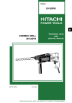
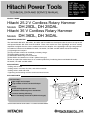
PRODUCT NAME
Hitachi 25.2 V Cordless Rotary Hammer
Models
DH 25DL, DH 25DAL
Hitachi 36 V Cordless Rotary Hammer
Models DH 36DL, DH 36DAL
MARKETING OBJECTIVE
The new Models DH 25DL, DH 25DAL, DH 36DL and DH 36DAL are developed under the same concept as the
well-reputed Models DH 24DV and DH 24DVA. These new models are more lightweight and their working
capacities are higher than the current models thanks to the adoption of the lightweight and high-voltage lithiumion batteries. Features of the Models DH 25DL, DH 25DAL, DH 36DL and DH 36DAL include the following:
(1) Lightweight and compact
(2) Large number of holes can be drilled per battery charge.
(3) Fastest drilling speed in the class
(4) Switchable hammering force mechanism
(5) New lithium-ion batteries 25.2 V/36 V (Slide-in/out type)
We aim to expand the market share of our cordless products by introducing these new Models DH 25DL,
DH 25DAL, DH 36DL and DH 36DAL.
APPLICATIONS
• Drilling anchor holes
• Drilling holes in concrete, tile, brick, and similar materials
• Drilling holes in steel and wood
• Tightening and loosening machine screws and wood screws
SELLING POINTS
[ NEW FEATURES ]
Light weight and compact
Large number of holes can be drilled per
charge
Fastest drilling speed in the class
Switchable hammering force mechanism
increases working efficiency
New Li-ion battery 25.2 V/36 V (Slide-in/out type)
SPECIFICATIONS AND PARTS ARE SUBJECT TO CHANGE FOR IMPROVEMENT
International Sales Division
D
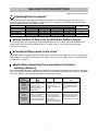
REMARK:
For more information about HANDLING INSTRUCTIONS, visit our website at:
http://www.hitachi-koki.com/manual_view_export/
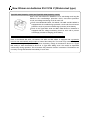
Throughout this TECHNICAL DATA AND SERVICE MANUAL, a symbol(s) is(are) used in the place of
company name(s) of out competitor(s). The symbol(s) utilized here is(are) as follows:
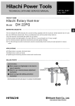
Symbols Utilized
B
Competitors
Company Name
Model Name
BOSCH
GBH36V-LI
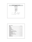
CONTENTS
Page
SELLING POINT DESCRIPTIONS -----------------------------------------------------------------------------------------1
SPECIFICATIONS --------------------------------------------------------------------------------------------------------------3
COMPARISONS WITH SIMILAR PRODUCTS--------------------------------------------------------------------------5
1. Specifications comparisons ------------------------------------------------------------------------------------5
2. Drilling speed comparisons ------------------------------------------------------------------------------------6
3. Chiseling performance comparisons-------------------------------------------------------------------------7
4. Per charge working capacity comparisons -----------------------------------------------------------------8
PRECAUTIONS IN SALES PROMOTION--------------------------------------------------------------------------------9
1. Safety instructions -----------------------------------------------------------------------------------------------9
2. Precautions requiring particular attention during sales promotion --------------------------------- 11
REFERENCE MATERIALS------------------------------------------------------------------------------------------------- 11
REPAIR GUIDE---------------------------------------------------------------------------------------------------------------- 12
1. Precautions in disassembly and reassembly (DH 25DL, DH 36DL) ------------------------------- 12
2. Precautions in disassembly and reassembly (DH 25DAL, DH 36DAL) --------------------------- 17
3. Precautions in servicing (DH 25DL, DH 25DAL, DH 36DL, DH 36DAL) -------------------------- 24
4. Precautions in disassembly and reassembly of battery charger ------------------------------------ 25
STANDARD REPAIR TIME (UNIT) SCHEDULES-------------------------------------------------------------------- 26
Assembly diagram for DH 25DL
Assembly diagram for DH 25DAL
Assembly diagram for DH 36DL
Assembly diagram for DH 36DAL
SELLING POINT DESCRIPTIONS
*: Based on our own research
Lightweight and compact *
The Models DH 25DL, DH 25DAL, DH 36DL and DH 36DAL are substantially lighter than the current
models in weight thanks to the adoption of the new lithium-ion batteries Types BSL 2530 and BSL 3626.
They are lighter than B by over 300 g in weight.
Maker
Model
Overall length (mm)
Overall height (mm)
Overall width (m)
Weight (kg)
DH 25DL
322
192
93
3.5
HITACHI
DH 25DAL
DH 36DL
322
322
192
214
93
93
3.6
3.9
DH 36DAL
322
214
93
4.0
B
367
221
96
4.3
Large number of holes can be drilled per battery charge *
The working capacity per single charge of the Model DH 36DAL is 1.5 to 2 times higher than B thanks to the
highly efficient motor and the high-capacity battery. For details, refer to "4. Per charge working capacity
comparisons" on page 8.
Fastest drilling speed in the class *
The drilling speed of the Models DH 25DL, DH 25DAL, DH 36DL and DH 36DAL are about 1.1 times higher
than B thanks to the efficient transmission of the hammering energy. For details, refer to "2. Drilling speed
comparisons" on page 6.
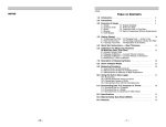
Switchable hammering force mechanism increases
working efficiency
Each of the Models DH 25DL, DH 25DAL, DH 36DL and DH 36DAL is equipped with the same mechanism
as the current DH 24 series cordless rotary hammers to switch the hammering force between "POWER"
mode and "SAVE" mode for proper adjustment of the hammering force.
Change lever
“Rotation + hammering”
“Rotation only”
“Hammering only
<Drilling holes in concrete>
Suitable for drilling holes
of 5 mm or larger
diameter with high motor
power (speedy and
efficient drilling)
<Drilling holes in steel and wood>
Suitable for drilling holes
in steel and wood
speedily with high motor
power
<Demolishing concrete>
Suitable for demolishing
hard materials such as
concrete with high motor
power
<Drilling holes in concrete>
Suitable for drilling holes
of 4.8 mm or smaller
diameter with suppressed
motor power (preventing
the bit from being bent)
<Nonusable>
Do not use the tool for
high-load operation in
this mode because the
motor power is
suppressed. Otherwise,
the motor may be burnt
out.
<Demolishing blocks>
Suitable for demolishing
brittle materials such as
blocks and bricks with
suppressed motor power
Shift knob
“POWER”
mode
(Powerful
hammering
force)
“SAVE”
mode
(Suppressed
hammering
force)
1
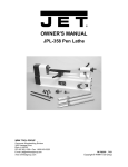
New lithium-ion batteries 25.2 V/36 V (Slide-in/out type)
Type BSL 2530 (Capacity: 3.0 Ah) and Type BSL 3626 (Capacity: 2.6 Ah)
Each of the new lithium-ion batteries is of a safe design and long-life
thanks to the overdischarge protection circuit, overcurrent protection
circuit, and voltage monitoring circuit for each cell.
Each of the Models DH 25DL, DH 25DAL, DH 36DL and DH 36DAL is
equipped with the overdischarge protection circuit and the overcurrent
protection circuit to prevent overdischarge (overuse) of the battery.
Each of the Types BSL 2530 and BSL 3626 lithium-ion batteries is
equipped with the voltage monitoring circuit for each cell to prevent
overcharge (excessive charging) of the battery.
Precautions for use of the Types BSL 2530 and BSL 3626 lithium-ion batteries
Each of the Models DH 25DL, DH 25DAL, DH 36DL and DH 36DAL is equipped with a protective
function that automatically stops output to extend the battery life. The motor may automatically stop
when the remaining battery level is low (when the battery voltage is decreased to about 14 V (Type
BSL 2530) or when decreased to about 20 V (Type BSL 3626)) even if the switch is depressed
continuously during operation. This is because the protective function is activated. The batteries are
not faulty. Charge the batteries immediately in such case.
-2-
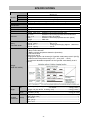
SPECIFICATIONS
DH 25DL, DH 25DAL
26 mm (1”)
Model
Concrete
Steel
Wood
Usable drill bits
No-load rotation speed
Full-load blow
Type of motor
Type of switch
Type of handle
Capacity
Enclosure
Battery
(Type: BSL 2530)
13 mm (1/2”)
30 mm (1-1/4”)
SDS-plus type only
“POWER” mode: 1,100 min –1 , “SAVE” mode: 550 min -1
“POWER” mode: 4,500 min –1 , “SAVE” mode: 2,250 min -1
DC magnet motor
Trigger switch with forward/reverse rotation selector (with brake)
D-type handle of main body and side handle
Housing, gear cover -- Glassfiber reinforced polyamide resin
Grip cover --------------- Glassfiber reinforced polycarbonate and elastomer
Inner cover -------------- Aluminum alloy die casting
Battery ------------------- Glassfiber reinforced polycarbonate resin (black)
Charger ------------------ ABS resin
Sealed cylindrical lithium-ion storage battery
Nominal voltage ----------------------- DC 25.2 V
Nominal life ----------------------------- Charging/discharging: Approx. 1,000 times
Nominal capacity ---------------------- 3.0 Ah
Overcharge protection system:
(1) Stop current detection
(2) Battery surface temperature detection (thermistor)
(3) 180-minute timer
Power input: 100 W
Charging time: Approx. 60 minutes [for Type BSL 2530 battery at 20°C (68°F)]
Operable ambient temperature range: 0°C - 40°C (32°F - 104°F)
The maximum allowable temperature of the Type BSL 2530 battery is 50°C
(122°F).
Charger
(Model UC 36YRL)
36
Net
Weight
Gross
Standard
(2LRK)
accessories
Main body unit (including battery) DH 25DL ------------------------- 3.5 kg (7.7 lbs.)
DH 25DAL ----------------------- 3.6 kg (7.9 lbs.)
Charger unit (UC 36YRL, including cord) ---------------------------- 0.9 kg (2.0 lbs.)
DH 25DL (2LRK) ----------------------------------------------------------- 8.2 kg (18.0 lbs)
DH 25DAL (2LRK) --------------------------------------------------------- 8.3 kg (18.3 lbs)
Charger (UC 36YRL) ------------------------------------------------------------------------1
Battery (BSL 2530) --------------------------------------------------------------------------2
Side handle ------------------------------------------------------------------------------------1
Depth gauge-----------------------------------------------------------------------------------1
Plastic case ------------------------------------------------------------------------------------1
-3-
DH 36DL, DH 36DAL
Model
Capacity
26 mm (1”)
Concrete
Steel
13 mm (1/2”)
Wood
30 mm (1-1/4”)
SDS-plus type only
Usable drill bits
No-load rotation speed “POWER” mode: 1,100 min –1 ,
“POWER” mode: 4,500 min –1 ,
Full-load blow
DC magnet motor
Type of motor
Type of switch
Type of handle
Enclosure
Battery
(Type: BSL 3626)
“SAVE” mode: 550 min –1
“SAVE” mode: 2,250 min -1
Trigger switch with forward/reverse rotation selector (with brake)
Gun-type handle of main body and side handle
Housing, gear cover -- Glassfiber reinforced polyamide resin
Grip cover --------------- Glassfiber reinforced polycarbonate and elastomer
Inner cover -------------- Aluminum alloy die casting
Battery ------------------- Glassfiber reinforced polycarbonate resin (black)
Charger ------------------ ABS resin
Sealed cylindrical lithium-ion storage battery
Nominal voltage ------------------------DC 36V
Nominal life ------------------------------Charging/discharging: Approx. 1,000 times
Nominal capacity -----------------------2.6 Ah
Overcharge protection system:
(1) Stop current detection
(2) Battery surface temperature detection (thermistor)
(3) 180-minute timer
Power input: 100 W
Charging time: Approx. 80 minutes [for Type BSL 3626 battery at 20°C (68°F)]
Operable ambient temperature range: 0°C - 40°C (32°F - 104°F)
The maximum allowable temperature of the Type BSL 3626 battery is 50°C
(122°F).
Charger
(Model UC 36YRL)
36
Weight
Net
Gross
Standard
(2LRK)
accessories
Main body unit (including battery) DH 36DL ------------------------- 3.9 kg (8.6 lbs.)
DH 36DAL ----------------------- 4.0 kg (8.8 lbs.)
Charger unit (UC 36YRL, including cord) ---------------------------- 0.9 kg (2.0 lbs.)
DH 36DL (2LRK) ----------------------------------------------------------- 8.8 kg (19.4 lbs)
DH 36DAL (2LRK) --------------------------------------------------------- 8.9 kg (19.6 lbs)
Charger (UC 36YRL) ------------------------------------------------------------------------1
Battery (BSL 3626) --------------------------------------------------------------------------2
Side handle ------------------------------------------------------------------------------------1
Depth gauge-----------------------------------------------------------------------------------1
Plastic case ------------------------------------------------------------------------------------1
-4-
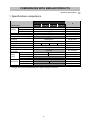
COMPARISONS WITH SIMILAR PRODUCTS
(Superior specifications:
1. Specifications comparisons
Maker
HITACHI
B
Model name
Concrete
Steel
Wood
No-load rotation speed
Full-load blow
Changeover of impact energy
DH 25DL
DH 25DAL DH 36DL DH 36DAL
26 mm (1”)
13 mm (1/2”)
30 mm (1-1/4")
(P) mode: 1,100 min –1, (S) mode: 550 min –1
(P) mode: 4,500 min –1, (S) mode: 2,250 min –1
Equipped
26 mm (1”)
13 mm (1/2”)
30 mm (1-1/4")
960 min –1
4,260 min –1
Not indicated
Bit setting
Single action
Single action
Reversing switch
Push-button
Push-button
Capacity
Changeover modes
2 modes
3 modes
2 modes
3 modes
Soft grip handle
Equipped (Handle)
Variable speed
Equipped
Internal pressure adjustment
Equipped
mechanism
Nominal capacity
3.0 Ah
2.6 Ah
Nominal voltage
25.2 V
36 V
Battery
(Li-ion)
Protection circuit
Equipped
60 min
80 min
Charging time*1
Overall length
322 mm
Dimensions Overall height
192 mm
214 mm
Overall width
93 mm
Weight
3.5 kg
3.6 kg
3.9 kg
4.0 kg
*1 : Charging time may vary depending on the type of charger to be used.
-5-
3 modes
Equipped (Handle)
Equipped
Not indicated
2.0 Ah
36 V
Not indicated
60 min
367 mm
221 mm
96 mm
4.3 kg
)
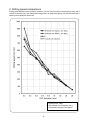
2. Drilling speed comparisons
Drilling speed depends on the operating conditions. The test result is based on actual factory tests, and is
used as a reference only. The drilling speed comparisons for downward drilling. The drill bits used are the
Hitachi genuine SDS-plus shank bits.
Pressing force: 10kgf
Test material: Concrete panel with a
compression strength of 240 kgf/cm2
-6-
3. Chiseling performance comparisons
Chiseling performance varies considerably depending on the work conditions. Use the factory test results
shown below for comparison purposes only.
-7-
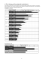
4. Per charge working capacity comparisons
The number of holes which can be drilled into concrete per battery charge may vary widely in accordance
with the hardness of the concrete, sharpness and condition of the drill bit and other factors. Accordingly, the
test results are intended for reference purposes only.
(1) Drilling into concrete
(2) Chiseling concrete
-8-
PRECAUTIONS IN SALES PROMOTION
1. Safety instructions
In the interest of promoting the safest and most efficient use of the Models DH 25DL/DH 25DAL/DH 36DL/
DH 36DAL Cordless Rotary Hammers by all of our customers, it is very important that at the time of sale,
the salesperson carefully ensures that the buyer seriously recognizes the importance of the contents of the
Handling Instructions, and fully understands the meaning of the precautions listed on the Caution Plate and
Name Plate attached to each tool.
A. Handling Instructions
Salespersons must be thoroughly familiar with the contents of the Handling Instructions in order to give
pertinent advice to the customer. In particular, they must have a thorough understanding of the precautions
for use of the cordless tools which are different from those of ordinary electric power tools.
(1) Before use, ensure that the unit is fully charged.
New units are not fully charged. Even if the units were fully charged at the factory, long periods of
inactivity, such as during shipping, cause the storage battery to lose its charge. Customers must be
instructed to fully charge the unit prior to use.
(2) Connect the charger to an AC power outlet only.
Use of any other power source (DC outlet, fuel powered generator, etc.) will cause the charger to
overheat and burn out.
(3) Do not use any voltage increasing equipment (transformer etc.) between the power source and the charger.
If the charger is used with voltage higher than that indicated on the unit, it will not function properly.
(4) Conduct battery charging at an ambient temperature range of 0°C - 40°C (32°F - 104°F).
Special temperature sensitive devices are employed in the charger to permit rapid charging. Ensure that
customers are instructed to use the charger at the indicated ambient temperature range. At temperature
under 0°C (32°F) the thermostat will not function properly, and the storage battery may be overcharged.
At temperature over 40°C (104°F), the storage battery cannot be sufficiently charged. The optimum
temperature range is 20°C - 25°C (68°F - 77°F).
(5) The battery charger should not be used continuously.
At high ambient temperature, if over three storage batteries are charged in succession, the temperature
of the coils on the transformer will rise and there is a chance that the temperature fuse inserted in the
interior of the transformer will inadvertently melt. After charging one battery, please wait about 15
minutes before charging the next battery.
(6) Do not insert foreign objects into the air vents on the charger.
The charger case is equipped with air vents to protect the internal electronic components from
overheating. Caution the customer not to allow foreign materials, such as metallic or flammable objects,
to be dropped or inserted into the air vents. This could cause electrical shock, fire, or other serious
hazards.
(7) Do not attempt to disassemble the storage battery or the charger.
Special devices, such as a thermostat, are built into the storage battery and charger to permit rapid
charging. Incorrect parts replacement and/or wiring will cause malfunctions which could result in fire or
other hazards. Instruct the customer to bring these units to an authorized service center in the event
repair or replacement is necessary.
(8) Disposal of the storage batteries
Ensure that all customers understand that the storage batteries should be returned to the Hitachi power
tool sales outlet or the authorized service center when they are no longer capable of being recharged or
repaired. If thrown into a fire, the battery may explode, or, if discarded indiscriminately, leakage of the
cadmium compound contained in the battery may cause environmental pollution.
-9-
B. Caution Plate
(1) The following cautions are listed on the Name Plate attached to the main body of each tool.
[ For the U.S.A. and Canada ]
(2) The following cautions are listed on the name plate attached to each storage battery.
[ For Europe ]
[ For the U.S.A. and Canada ]
(3) The following cautions are listed on the Name Plate attached to the Model UC 36YRL Charger.
CAUTION
For safe operation, see instruction manual.
Charge HITACHI rechargeable batteries types BSL 2530 and
BSL 3626 series. Other types of batteries may burst causing
personal injury and damage.
Charge between 32qF and 104qF. Rest 15 minutes between
the charging of batteries.
Indoor use only.
Replace defective cord immediately.
-10-
2. Precautions requiring particular attention during sales promotion
The cordless rotary hammer offers many advantages: it can be used in places where no power source is
available, the absence of a cord allows easy use, etc. However, in comparison with conventional AC type
impact drills and hammer drills, there are certain precautions which require particular attention.
Salespersons must be thoroughly familiar with the following points to properly advise the customer in the
most efficient use of the tool.
A. Suggestions and precautions for the efficient use of the tool
(1) Appropriate drilling capacity of the Model DH 25DL/DH 25DAL/DH 36DL/ DH 36DAL
The Models DH 25DL, DH 25DAL, DH 36DL and DH 36DAL are not capable of drilling several dozens
of holes like a conventional AC type impact or hammer drill because it is a cordless rotary hammer
powered by a battery. If the customer wishes to use the tool to drill many holes in succession, please
recommend that a spare battery should be kept available for use.
(2) Use thrust within the range of 10 to 15 kg
Applying heavy thrust (pressure) on the tool, such as is possible with AC type impact and hammer drills,
will not accelerate the drilling speed. On the contrary, excessive pressure will reduce bit rotation and
hammering speed, and cause the storage battery to rapidly lose its charge.
(3) Variation in amount of work possible per charge
Although the nominal capacity of the storage batteries used with the Models DH 25DL/DH 25DAL are
3.0 Ah Models DH 36DL/DH 36DAL are 2.6 Ah, the Actual capacity may vary within 10% of that value
depending on the ambient temperature during use and recharging, and the number of times the
batteries have been recharged. It should also be noted that other factors which may have a bearing on
the amount of work possible per charge are the working conditions (ambient temperature, type and
moisture content of the workpieces, sharpness of the drill bits, etc.) and the operational skill of the user.
(4) Precautions in drilling with metal drill bits.
Although the Models DH 25DL, DH 25DAL, DH 36DL and DH 36DAL are designed for a drilling capacity
of up to 13 mm in steel, its operational capabilities are considerably less than those of conventional AC
type impact drills. Especially when drilling with a 13 mm drill bit for steel, the drill tends to become
locked when the drill bit penetrates through the material. For this reason, the customer should be
cautioned to reduce the pressure on the main body of the tool when drilling completely through the
material to avoid locking the drill.
REFERENCE MATERIALS
The main components of the striking mechanism section and the tool retainer section of the Models
DH 25DL and DH 36DL are common to those of the Model DH 24DV, and the main components of the
striking mechanism section and the tool retainer of the Models DH 25DAL and DH 36DAL are common to
those of the Model DH 24DVA. Refer to the Technical Data and Service Manuals of the Model DH 24DV
(No. G811) and the Model DH 24DVA (No. G842) for details of the following.
1. Lubrication
2. Tool structure
3. 3-mode changeover mechanism (Models DH 25DAL and DH 36DAL)
"Rotation only" and "Rotation and hammering" changeover mechanism (Models DH 25DL and DH 36DL)
4. "Rotation only" (no striking)
5. Drill bits
6. Tool retainer section
7. Dust collector (B)
-11-
REPAIR GUIDE
Be sure to remove the storage batteries from the main body before servicing. Inadvertent triggering of the
switch with the storage battery connected will result in danger of accidental turning of the motor.
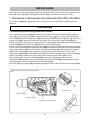
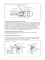
1. Precautions in disassembly and reassembly (DH 25DL, DH 36DL)
The numbers in [Bold] correspond to the item numbers in the Parts Lists and the exploded assembly
diagrams.
Disassembly
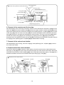
1. Disassembly of the striking mechanism section
Push in the Second Hammer [26] with a drill bit or a screwdriver. Remove the Striker [34] chucked by Oring (C) [31]. The Change Lever [20] is positioned “Rotation Only” ( mark). Remove the Tapping Screw
D2.6 x10 [19] and turn the Change Lever [20] by approximately 200q clockwise. Adjust the “ ” mark of the
Change Lever [20] to the center of the notch on the gear cover. Ply out the Change Lever [20] at this
position. Remove the Tapping Screw (W/Flange) D5 x 25 (Black) [9] and the Tapping Screw (W/Flange) D5
x 30 (Black) [82] from the Gear Cover [10] and remove the Gear Cover [10].
The Inner Cover Ass’y [39] and Housing (A). (B) Set [66] are loosely fitted together. Attempting to pull them
out first could cause the Armature and Pinion Ass’y [55] to be pulled out at the same time, causing damage
to the Carbon Brushed [61]. Remove from the end of the Second Shaft [41], and turn the Second Shaft
[41] so that the Piston [36] moves to its maximum upper position (inner cover side). The arm of the
Reciprocating Bearing [46] can then be disconnected from the Piston Pin [45], and the Second Shaft [41]
and the components mounted on it can be removed from the Inner Cover Ass'y [39] as a unit.
With a bearing puller, remove the First Gear [48] from the Second Shaft [41]. Then take off the
Reciprocating Bearing [46]. At this time, carefully note that the First Gear [48] must be aligned with and
press-fitted onto the 9 mm diameter end of the Second Shaft [41].
The Clutch [44], Clutch Spring [43] and Washer (B) [42] can then be removed from the Second Shaft [41].
Disassembly of the striking mechanism section
Notch
A
Viewed from “A”
Gear Cover [10]
Change Lever [20]
Tapping Screw D2.6 x10 [19]
Notch
-12-
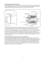
2. Disassembly of the tool retainer
Slide the Grip [3] fully in the arrow direction and remove the Front Cap [1]. Pulling the Grip [3], remove the
Stopper Ring [2] with a retaining ring puller. Then the Grip [3], Ball Holder [4], Steel Ball D7.0 [16], Holder
Plate [5], Holder Spring [6] and Washer (B) [7] can be removed from the Cylinder [17].
Disassembly of the tool retainer
Holder Plate [5]
Grip [3]
Holder Spring [6]
Grip [3]
Retaining
Ring
for D20
Shaft [8]
Steel Ball D7.0 [16]
Stopper Ring [2]
Front Cap [1]
Washer (B) [7]
Ball Holder [4]
3. Disassembly of the cylinder and the second gear (slip mechanism section)
Remove the Gear Cover [10] from the Inner Cover Ass'y [39] and remove the entire tool retainer. Remove
the Retaining Ring for D20 Shaft [8] with a retaining ring puller. Stand the Gear Cover [10] in this state and
pull out the Cylinder [17] from the Gear Cover [10] with a hand press. Then Sleeve (A) [14] can be
removed from the Cylinder [17]. Remove the Retaining Ring for D30 Shaft [25] from the Cylinder [17] with
a retaining ring puller. Then the Second Gear [22], Spring (A) [23] and Washer (A) [24] can be removed
from the Cylinder [17].
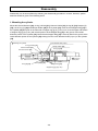
4. Disassembly of the cylinder and the second hammer
Remove the Stopper Ring [33] from the inside diameter portion of the Cylinder [17]. Then the Second
Hammer [26], O-ring (1AP-20) [27], Hammer Holder [28], O-ring (B) [29], Damper (A) [30], O-ring (C) [31]
and Damper Holder [32] can be removed from the Cylinder [17]. Remove the Stopper Ring [33] from the
groove of the inside diameter portion of the Cylinder [17] by tapping the Stopper Ring [33] through the 5mm diameter hole of the Cylinder [17] with a hammer and a punch. At reassebmly, replace the Stopper
Ring [33] with new one as the removed Stopper Ring [33] is deformed. To prevent idle hammering, also
replace O-ring (C) [31] with new one at reassembly.
-13-
Disassembly of the cylinder and the second hammer
Tap with a hammer.
Punch
5-mm diameter hole (2 pcs.)
O-ring (1AP-20) [27]
Damper Holder [32]
Hammer Holder [28]
O-ring (C) [31]
Second Hammer [26]
O-ring (B) [29]
Damper (A) [30]
Stopper Ring [33]
5. Disassembly of the armature and the housing
After disassembly of the striking mechanism section, remove the Machine Screw M4 x 8 [81] from the Grip
Cover [80] and remove the Grip Cover [80] to show the carbon brushes. Hook the Spring [59] on the edge
of the carbon brush tube. Remove the Tapping Screw (W/Flange) D4 x 16 (Black) [52] from the Inner Cover
Ass'y [39]. Then the Inner Cover Ass'y [39] can be removed together with the Armature and Pinion Ass'y
[55]. At this time, be careful not to damage the carbon brushes. The Inner Cover Ass'y [39] and the
Armature and Pinion Ass'y [55] can be removed just by pressing the Pinion [50] slightly with a press
because there is an interference of the O-ring (P-22) [53]. The housing is constructed of two parts. Remove
the Tapping Screw (W/Flange) D4 x 20 (Black) [63] to disassemble the housing.
6. Disassembly of the carbon brush holder
After disassembly of the housing, remove the Tapping Screw (W/Flange) D4 x 16 (Black) [52] to
disassemble the carbon brush holder.
7. Replacement of the carbon brushes
Remove the Grip Cover [80] to show the carbon brushes. Pinch the terminal of the Carbon Brush [61] with
a pair of long-nose pliers and pull it out of the carbon brush holder. Hook the Spring [59] on the Carbon
Brush [61] with a flat-blade screwdriver and remove the Carbon Brush [61].
Replacement of the carbon brushes
Long-nose pliers
Terminal
Spring [59]
Carbon
Brush [61]
Flat-blade
screwdriver
-14-
Reassembly
Reassembly can be accomplished by following the disassembly procedure in reverse. However, special
attention should be given to the following items.
1. Mounting the change lever
Position the Change Lever [20] on the Gear Cover [10] and push it in firmly. Adjust the Change Lever [20]
to the position where “ ” mark points in the upward direction. Tighten the Tapping Screw D2.6 x 10 [19].
Mounting the change lever
Notch
A
Viewed from “A”
Change Lever [20]
Tapping Screw D2.6 x 10 [19]
Notch
2. Press-fitting the first gear
Press-fit the First Gear [48] aligning with the shaft end surface of the Second Shaft [41]. After press-fitting
the First Gear [48], check that the inside ring of the Reciprocating Bearing [46] turns smoothly.
3. Reassembly of the oil seal
Prior to reassembly, apply grease to the inner circumference of the Oil Seal [11]. However, do not apply
grease to its outer circumference. Also, when press-fitting the Oil Seal [11], ensure that it is straight and
level.
4. Mounting the piston
Mount the Piston [36] facing its two 2-mm diameter holes to the Second Shaft [41].
Mounting the piston
Piston [36]
Inner Cover Ass'y [39]
Striker [34]
Second Shaft [41]
2-mm daimeter hole (2 pcs.)
Reciprocating
Bearing [46]
-15-
First Gear [48]
Application of lubricant
Apply special grease (for hammer and hammer drill) to the O-ring (1AP-20) [27] and O-ring (B) [29] for the
Hammer Holder [28], Damper (A) [30], O-ring (C) [31], O-ring (I.D.16) [35] for the Striker [34], outer
circumference of the Striker [34], inner and outer circumference of the Piston Pin [45], outer circumference
of the Piston [36], Reciprocating Bearing [46], Reciprocating Bearing [46] rotary shaft of the Second Shaft
[41], clutch claw of the Cylinder [17], inner circumference of the metal of the Inner Cover Ass’y [39],
Second Hammer [26], and the lip portion of the Oil Seal [11]. Fill 45 g of the special grease in the gear
cover and 5 g in the inner cover groove. Apply Molub Alloy No. 777-1 grease to the outer circumference of
the Clutch [44] groove and the pin portion of the Change Lever [20]. Apply HITACHI Motor Grease No. 29
to the O-ring (S-18) [21] for the Steel Ball D7.0 [16] and the Change Lever [20].
* Application of Hitachi Motor Grease No. 29 makes it easy to mount the Spacer [49].
-16-
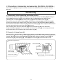
2. Precautions in disassembly and reassembly (DH 25DAL, DH 36DAL)
The numbers in [Bold] correspond to the item numbers in the Parts Lists and the exploded assembly
diagrams.
Disassembly
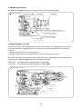
1. Disassembly of the hammering mechanism section
Push in the Second Hammer [30] with a drill bit or a screwdriver. Remove the Striker [38] chucked by Oring (C) [35]. Remove the Tapping Screw (W/Flange) D5 x 25 (Black) [9] and the Tapping Screw
(W/Flange) D5 x 30 (Black) [88] from Gear Cover (A) [10] and remove Gear Cover (A) [10].
Remove from the end of Second Shaft (A) [50], and turn Second Shaft (A) [50] so that the Piston [40]
moves to its maximum upper position (inner cover side). The arm of the Reciprocating Bearing [52] can
then be disconnected from the Piston Pin [51], and Second Shaft (A) [50] and the components mounted on
it can be removed from the Inner Cover Ass'y [43] as a unit.
With a bearing puller, remove the First Gear [54] from Second Shaft (A) [50]. Then take off the
Reciprocating Bearing [52]. At this time, carefully note that the First Gear [54] must be aligned with and
press-fitted onto the 9 mm diameter end of Second Shaft (A) [50].
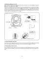
2. Removal of change lever (A)
Remove the Tapping Screw D2.6 x 10 [23] and turn Change Lever (A) [20] counterclockwise (in the arrow
direction) until “ ” mark on Change Lever (A) [20] points right below. Then Change Lever (A) [20] can be
removed. Be careful not to lose the Steel Ball D3.97 [24]. After removal of Change Lever (A) [20], the
Second Pinion [44], Clutch Spring [45], Clutch [46] and Lock Plate [49] can be removed as a unit.
Removal of change lever (A)
Second Pinion [44]
Clutch [46]
Tapping Screw
D2.6 x 10 [23]
Change Lever (A) [20]
Lock Plate [49]
-17-
Clutch Spring [45]
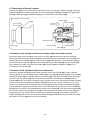
3. Disassembly of the tool retainer
Slide the Grip [3] fully in the arrow direction and remove the Front Cap [1]. Pulling the Grip [3], remove the
Stopper Ring [2] with a retaining ring puller. Then the Grip [3], Ball Holder [4], Steel Ball D7.0 [17], Holder
Plate [5], Holder Spring [6] and Washer (B) [7] can be removed from the Cylinder [18].
Disassembly of the tool retainer
Holder Plate [5]
Grip [3]
Holder Spring [6]
Retaining
Ring for D20
Shaft [8]
Steel Ball D7.0 [17]
Stopper Ring [2]
Front Cap [1]
Washer (B) [7]
Ball Holder [4]
4. Removal of the cylinder and the second gear (slip mechanism section)
Remove the Gear Cover (A) [10] from the Inner Cover Ass'y [43] and remove the entire tool retainer.
Remove the Retaining Ring for D20 Shaft [8] with a retaining ring puller. Stand Gear Cover (A) [10] in this
state and pull out the Cylinder [18] from Gear Cover (A) [10] with a hand press. Then the Sleeve [12] can
be removed from the Cylinder [18]. Remove the Retaining Ring for D30 Shaft [29] from the Cylinder [18]
with a retaining ring puller. Then the Second Gear [26], Spring (A) [27] and Washer (A) [28] can be
removed from the Cylinder [18].
5. Removal of the cylinder and the second hammer
Remove the Stopper Ring [37] from the inside diameter portion of the Cylinder [18]. Then the Second
Hammer [30], O-ring (1AP-20) [31], Hammer Holder [32], O-ring (B) [33], Damper (A) [34], O-ring (C) [35]
and Damper Holder [36] can be removed from the Cylinder [18]. Insert the no-hole side of stopper ring jig
(A) (J-341) into the Cylinder [18] until it contacts the end surface of the Damper Holder [36]. Hold the
Cylinder [18] and the end surface of stopper ring jig (A) (J-341) with a vise, and compress Damper (A) [34]
(it moves a little when the Stopper Ring [37] is pressed with punch (C) (J-341)). Insert punch (C) (J-341)
into the 5-mm diameter holes (2 places) in the Cylinder [18] and tap the outside of the Stopper Ring [37]
until the Stopper Ring [37] cannot be seen from the 5-mm diameter holes (2 places) to remove the Stopper
Ring [37] from the groove of the inside diameter portion of the Cylinder [18]. Then remove the Cylinder [18]
from the vise and pull out the Stopper Ring [37] from the inside diameter portion of the Cylinder [18] with
ring puller jig (B) (J-341) being careful not to pop out the Stopper Ring [37]. At reassebmly, replace the
Stopper Ring [37] with new one as the removed Stopper Ring [37] is deformed. To prevent idle hammering,
also replace O-ring (C) [35] with new one at reassembly.
-18-
Removal of the cylinder and the second hammer
Tap with a hammer.
Punch (C) (J-341)
5-mm diameter hole (2 pcs.)
O-ring (1AP-20) [31]
Damper Holder [36]
Hammer Holder [32]
O-ring (C) [35]
Second Hammer [30]
Vise
O-ring (B) [33]
Damper (A) [34]
Stopper Ring [37]
Stopper ring jig (A) (J-341)
6. Removal of the armature and the housing
After disassembly of the hammering mechanism section, remove the Machine Screw M4 x 8 [87] from the
Grip Cover [86] and remove the Grip Cover [86] to show the carbon brushes. Hook the Spring [65] on the
edge of the carbon brush tube. Remove the Tapping Screw (W/Flange) D4 x 16 (Black) [58] from the Inner
Cover Ass'y [43]. Then the Inner Cover Ass'y [43] can be removed together with the Armature and Pinion
Ass'y [61]. At this time, be careful not to damage the carbon brushes. The Inner Cover Ass'y [43] and the
Armature and Pinion Ass'y [61] can be removed just by pressing the Pinion [56] slightly with a press
because there is an interference of the O-ring (P-22) [59]. The housing is constructed of two parts. Remove
the Tapping Screw (W/Flange) D4 x 20 (Black) [69] to disassemble the housing.
7. Removal of the carbon brush holder
After disassembly of the housing, remove the Tapping Screw (W/Flange) D4 x 16 (Black) [58] to remove
the carbon brush holder.
8. Replacement of the carbon brushes
Remove the Grip Cover [86] to show the carbon brushes. Pinch the terminal of the Carbon Brush (Auto
Stop Type) (1 Pair) [67] with a pair of long-nose pliers and pull it out of the carbon brush holder. At this time,
melt solder at the terminal. Hook the Spring [65] on the Carbon Brush (Auto Stop Type) (1 Pair) [67] with a
flat-blade screwdriver and remove the Carbon Brush (Auto Stop Type) (1 Pair) [67].
Replacement of the carbon brushes
Long-nose pliers
Terminal
Carbon
Brush (Auto
Stop Type)
(1 Pair) [67]
-19-
Spring [65]
Flat-blade
screwdriver
Reassembly
Reassembly can be accomplished by following the disassembly procedure in reverse. However, special
attention should be given to the following items.
1. Mounting the cylinder
Mount the Second Hammer [30], O-ring (1AP-20) [31], Hammer Holder [32], O-ring (B) [33], Damper (A)
[34], new O-ring (C) [35] and Damper Holder [36] in the Cylinder [18]. Push the new Stopper Ring [37] in
the Cylinder [18] then push in the hole side of stopper ring jig (A) (J-341) on it. Push the upper end surface
of stopper ring jig (A) (J-341) with a hand press to fit the Stopper Ring [37] in the groove of the inside
diameter portion of the Cylinder [18]. Check that the Stopper Ring [37] is securely fitted in the groove of the
inside diameter portion of the Cylinder [18] viewing from the 5-mm diameter holes (2 pcs.) on the Cylinder
[18].
5-mm diameter hole (2 pcs.)
Mounting the cylinder
O-ring (1AP-20) [31]
Damper Holder [36]
Hammer Holder [32]
O-ring (C) [35]
Second Hammer [30]
Hand press
O-ring (B) [33]
Damper (A) [34]
Stopper Ring [37]
Stopper ring jig (A) (J-341)
-20-
2. Mounting change lever (A)
Before mounting Change Lever (A) [20], reassemble the lock plate ass'y (Lock Plate [49], Second Pinion
[44], Clutch Spring [45] and Clutch [46]).
Mount the lock plate ass'y to rails (A) and (B) of Gear Cover (A) [10]. At this time, fit the Lock Plate [49]
properly in rail (A) and rail (B). Push in Spring (C) [48] and mount Change Lever (A) [20]. When mounting
Change Lever (A) [20], push in Change Lever (A) [20] strongly with the “ ” mark pointed right below in
the same manner as removal. Turn Change Lever (A) [20] within the range indicated with an arrow mark
and then tighten the Tapping Screw D2.6 x 10 [23].
Mounting change lever (A)
Fit in rail (A).
Fit in the inside of
Spring (C) [48].
Fit in rail (B).
Spring (C) [48]
Rail (A)
Rail (B)
Set the “
” mark of
Change Lever (A) [20]
within the range.
Mounting position
Tapping Screw D2.6 x 10 [23] tightening position
3. Press-fitting the first gear
Press-fit the First Gear [54] aligning with the shaft end surface of Second Shaft (A) [50]. After press-fitting
the First Gear [54], check that the inside ring of the Reciprocating Bearing [52] turns smoothly.
4. Reassembly of the oil seal
Prior to reassembly, apply grease to the inner circumference of the Oil Seal [11]. However, do not apply
grease to its outer circumference. Also, when press-fitting the Oil Seal [11], ensure that it is straight and
level.
-21-
5. Mounting the piston
Mount the Piston [40] facing its two 2-mm diameter holes to Second Shaft (A) [50].
Mounting the piston
Inner Cover Ass’y [43]
Striker [38]
Piston [40]
2-mm diameter holes (2 pcs.)
Second Shaft (A) [50]
Reciprocating Bearing [52]
First Gear [54]
6. Mounting gear cover (A)
First, mount Change Lever (A) [20] and the lock plate ass'y to Gear Cover (A) [10] then mount it to the
main body. At this time, engage the gear in 3 points (A, B and C) according to either of the following
methods:
1) Mount the drill bit and turn it by a hand slowly, or
2) Install the battery and pull the trigger switch for a quick moment to turn the motor.
Be careful when tightening the Tapping Screws (W/Flange) D5 x 25 (Black) [9] and the Tapping Screws
(W/Flange) D5 x 30 (Black) [88] because they are different in length.
Upper side … Two Tapping Screws (W/Flange) D5 x 25 (Black) [9]
Lower side … Two Tapping Screws (W/Flange) D5 x 30 (Black) [88]
Mounting gear cover (A)
A point
B point
C point
-22-
Application of lubricant
Apply special grease (for hammer and hammer drill) to the O-ring (1AP-20) [31] and O-ring (B) [33] for the
Hammer Holder [32], Damper (A) [34], O-ring (C) [35], O-ring (I.D.16) [39] for the Striker [38], outer
circumference of the Striker [38], inner and outer circumference of the Piston Pin [51], outer circumference
of the Piston [40], Reciprocating Bearing [52], Reciprocating Bearing [52] rotary shaft of Second Shaft (A)
[50], Second Pinion [44] rotary shaft, clutch claw of the Cylinder [18], inner circumference of the metal of
the Inner Cover Ass’y [43], Second Hammer [30], and the lip portion of the Oil Seal [11]. Fill 45 g of the
special grease in the gear cover and 5 g in the inner cover groove. Apply Molub Alloy No. 777-1 grease to
the pin portion of Change Lever (A) [20]. Apply Molub Alloy No. 777-1 grease to the contact portion
between the Clutch [46] and the Lock Plate [49]. Fill Molub Alloy No. 777-1 grease in the ball portion of the
Reciprocating Bearing [52]. Apply HITACHI Motor Grease No. 29 to the O-ring (S-18) [21] for the Steel Ball
D7.0 [17] and Change Lever (A) [20].
-23-
3. Precautions in servicing (DH 25DL, DH 25DAL, DH 36DL, DH 36DAL)
Wiring diagram
Wiring arrangement
Lead wire (White)
Lead wire (Red)
Lead wire (Red)
Lead wire (Black)
Lead wire (Blue)
Lead wire (Black)
Lead wire (Brown)
-24-
Tightening torque
Tapping Screw (W/Flange) D2.6 x 10 (Black)--------------------------------- 0.8 ± 0.2 N˹m (8 ± 2 kgf˹cm)
Tapping Screw (W/Flange) D4 (Black)------------------------------------------ 2.0 ± 0.5 N˹m (20 ± 5 kgf˹cm)
Tapping Screw (W/Flange) D5 x 25 (Black) ----------------------------------- 3.0 ± 0.5 N˹m (30 ± 5 kgf˹cm)
Tapping Screw (W/Flange) D5 x 30 (Black) ----------------------------------- 4.0 ± 0.5 N˹m (40 ± 5 kgf˹cm)
4. Precautions in disassembly and reassembly of battery charger
Please refer to the Technical Data and Service Manual for Model UC 36YRL for precautions in disassembly
and reassembly.
-25-
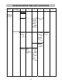
STANDARD REPAIR TIME (UNIT) SCHEDULES
MODEL
Variable
Fixed
10
20
30
40
50
Work Flow
DH 25DL
DH 36DL
Armature and
Housing
Pinion Ass’y
(A).(B) Set
O-ring (P-22)
Ball Bearing
(608DD)
Magnet
Ball Bearing
(608DD)
Brush Holder
DC-speed
Control Switch
Grip Cover
General Assembly
Second
Cylinder
Hammer Second Gear
O-ring (1AP-20) Spring (A)
Hammer
Holder
O-ring (B)
Damper (A)
O-ring (C)
Damper
Holder
Front Cap
Grip
Ball Holder
Holder
Spring
Steel Ball D7.0
Gear Cover
Oil Seal
Ball Bearing
(6904DD)
Sleeve (A)
Change Lever
O-ring (S-18)
Striker
O-ring
Piston
Washer (C) x 2
O-ring (I.D. 72)
Piston Pin
-26-
Inner Cover
Ass’y
Ball Bearing
(626VV)
Second Shaft
Clutch Spring
Clutch
Reciprocating
Bearing
Collar
First Gear
Pinion
Ball Bearing
(626VV)
60
MODEL
Variable
Fixed
10
20
30
40
50
Work Flow
DH 25DAL
DH 36DAL
Armature and
Housing
Pinion Ass’y
(A).(B) Set
O-ring (P-22)
Ball Bearing
(608DD)
Magnet
Ball Bearing
(608DD)
Brush Holder
DC-speed
Control Switch
Grip Cover
General Assembly
Second
Cylinder
Hammer Second Gear
O-ring (1AP-20) Spring (A)
Hammer
Holder
O-ring (B)
Damper (A)
O-ring (C)
Damper
Holder
Front Cap
Grip
Ball Holder
Holder
Spring
Steel Ball D7.0
Gear Cover
(A)
Oil Seal
Ball Bearing
(6904DD)
Sleeve (A)
Change
Lever (A)
O-ring (S-18)
Striker
O-ring
Piston
Washer (C) x 2
O-ring (I.D. 72)
Piston Pin
-27-
Inner Cover
Ass’y
Second
Shaft (A)
Pinion Sleeve
Spring (C)
Second
Pinion
Clutch Spring
Clutch
Lock Plate
Reciprocating
Bearing
Collar
First Gear
Pinion
Ball Bearing
(626VV)
60
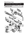
Hitachi Power Tools
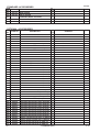
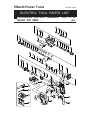
/,6712*
(/(&75,&722/3$576/,67
&25'/(66527$5<+$00(5
0RGHO'+'/
(
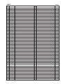
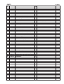
3$576
,7(0
12
'+'/
&2'(12
12
86('
'(6&5,37,21
)5217&$3
67233(55,1*
*5,3
%$//+2/'(5
+2/'(53/$7(
+2/'(5635,1*
:$6+(5%
5(7$,1,1*5,1*)25'6+$)73&6
7$33,1*6&5(::)/$1*(';%/$&.
*($5&29(5
2,/6($/
6/((9(
''
%$//%($5,1*''36/
6/((9($
5(7$,1,1*5,1*00
67((/%$//'3&6
&</,1'(5
+,7$&+,3/$7(*5((1
7$33,1*6&5(:';
&+$1*(/(9(5
25,1*6
6(&21'*($5
635,1*$
:$6+(5$
5(7$,1,1*5,1*)25'6+$)7
6(&21'+$00(5
25,1*$3
+$00(5+2/'(5
25,1*%
'$03(5$
25,1*&
'$03(5+2/'(5
67233(55,1*
675,.(5
25,1*,'
3,6721
:$6+(5&
25,1*,'
,11(5&29(5$66·<
990
%$//%($5,1*99&36/
6(&21'6+$)7
:$6+(5%
&/87&+635,1*
&/87&+
3,67213,1
5(&,352&$7,1*%($5,1*
&2//$5
),567*($5
63$&(5
3,1,21
990
%$//%($5,1*99&36/
5(0$5.6
,1&/8'
$/7(51$7,9(3$576
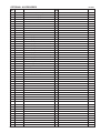
3$576
,7(0
12
'+'/
'(6&5,37,21
12
86('
7$33,1*6&5(::)/$1*(';%/$&.
&2'(12
25,1*3
''0
%$//%($5,1*''&36/
$50$785($1'3,1,21$66·<'&9
0$*1(7
:$6+(5$
''0
%$//%($5,1*''&36/
635,1*
%586++2/'(5
&$5%21%586+$87267237<3(3$,5
386+,1*%87721
7$33,1*6&5(::)/$1*(';%/$&.
1$0(3/$7(
%$77(5<%6/(8523($861=/
+286,1*$%6(7
'&63(('&21752/6:,7&+
,17(51$/:,5(5('
,17(51$/:,5(%/$&.
+,7$&+,/$%(/
&21752//(57(50,1$/6(7
+($76,1.
6+,)7.12%
0$&+,1(6&5(:::$6+(560;
58%%(5+2/'(5
18703&6
*5,3&29(5
0$&+,1(6&5(:0;3&6
7$33,1*6&5(::)/$1*(';%/$&.
&86+,21$
5(0$5.6
,1&/8'
$/7(51$7,9(3$576
'+'/
67$1'$5'$&&(6625,(6
,7(0
12
&2'(12
6,'(+$1'/(
'(37+*$8*(
&+$5*(502'(/8&<5/
C$6(
1
A
12
86('
'(6&5,37,21
2917
5(0$5.6
TECH. NEWS NO. 1574
237,21$/$&&(6625,(6
,7(0
12
&2'(12
+$00(5'5,//&+8&.6(700
&+8&.+$1'/(
58%%(5&$3
'5,//&+8&.$1'$'$37(56(7
&+8&.$'$37(5*6'63/86
'5,//&+8&.9/5%'
)/$7+'6&5(:$/()7+$1'0;
&+8&.:5(1&+)259/%'9/5'
'5,//&+8&.9/''
&+8&.+$1'/(
'867&83
67233(5
= '5,9(5%,7$12/
= '5,9(5%,7$12/
$1&+256(77,1*$'$37(5$:µ0$18$/
$1&+256(77,1*$'$37(5$:µ0$18$/
$1&+256(77,1*$'$37(5$:µ0$18$/
$1&+256(77,1*$'$37(5$:µ0$18$/
$1&+256(77,1*$'$37(5$:µ0$18$/
$1&+256(77,1*$'$37(5%:µ0$18$/
$1&+256(77,1*$'$37(5%:µ0$18$/
$1&+256(77,1*$'$37(5%:µ0$18$/
$1&+256(77,1*$'$37(5%:µ0$18$/
$1&+256(77,1*$'$37(5%:µ0$18$/
&277(5
7$3(56+$1.$'$37(56'63/8612
$7$3(56+$1.$'$37(56'63/86
%7$3(56+$1.$'$37(56'63/86
&+8&.$'$37(5'6'63/86
$1&+256(77,1*$'$37(5$6'6:;/
$1&+256(77,1*$'$37(5$6'6:;/
$1&+256(77,1*$'$37(5$6'6:;/
$1&+256(77,1*$'$37(5$6'6:;/
$1&+256(77,1*$'$37(5%6'6:;/
$1&+256(77,1*$'$37(5%6'6:;/
$1&+256(77,1*$'$37(5%6'6:;/
$1&+256(77,1*$'$37(5%6'6:;/
&+(0,&$/$1&+25$'$37(56'600;/
&+(0,&$/$1&+25$'$37(56'600;/
&25(%,76+$1.6'63/8600/
&25(%,76+$1.6'63/8600/
12
86('
'(6&5,37,21
5(0$5.6
,1&/8'
,1&/8'
,1&/8'
,1&/8'
$/7(51$7,9(3$576
'+'/
237,21$/$&&(6625,(6
,7(0
12
&2'(12
12
86('
'(6&5,37,21
&25(%,76+$1.6'63/8600/
'867&2//(&725%$66·<
62&.(7$'$37(5%
7$3(56+$1.'5,//%,7';
7$3(56+$1.'5,//%,7';
7$3(56+$1.'5,//%,7';
7$3(56+$1.'5,//%,7';
7$3(56+$1.'5,//%,7';
7$3(56+$1.'5,//%,7';
7$3(56+$1.'5,//%,7';
&25(%,7$00
&25(%,7$00
&25(%,7$00
*8,'(3/$7()25&25(%,700
&25(%,7$00
*8,'(3/$7()25&25(%,700
&25(%,7$00
*8,'(3/$7()25&25(%,700
&25(%,7%00
*8,'(3/$7()25&25(%,700
&25(%,7%00
*8,'(3/$7()25&25(%,700
&(17(53,1$/)25&25(%,7'
&(17(53,1%/)25&25(%,7'
*5($6($)25+$00(5+$00(5'5,//*
*5($6()25+$00(5+$00(5'5,//*
*5($6()25+$00(5+$00(5'5,//*
%8//32,176'6005281'6+$1.7<3(
5(0$5.6
,1&/8'
,1&/8'
,1&/8'
,1&/8'
,1&/8'
,1&/8'
$/7(51$7,9(3$576
'+'/
,7(0
12
&2'(12
'(6&5,37,21
12
86('
5(0$5.6
3ULQWHGLQ-DSDQ 1
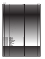
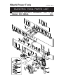
Hitachi Power Tools
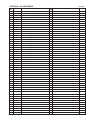
/,6712*
(/(&75,&722/3$576/,67
&25'/(66527$5<+$00(5
0RGHO'+'$/
(
3$576
,7(0
12
'+'$/
&2'(12
12
86('
'(6&5,37,21
)5217&$3
67233(55,1*
*5,3
%$//+2/'(5
+2/'(53/$7(
+2/'(5635,1*
:$6+(5%
5(7$,1,1*5,1*)25'6+$)73&6
7$33,1*6&5(::)/$1*(';%/$&.
*($5&29(5$
2,/6($/
6/((9(
)(/73$&.,1*%
''
%$//%($5,1*''36/
6/((9($
5(7$,1,1*5,1*00
67((/%$//'3&6
&</,1'(5
+,7$&+,3/$7(*5((1
&+$1*(/(9(5$
25,1*6
)(/73$&.,1*
7$33,1*6&5(:';
67((/%$//'3&6
635,1*+
6(&21'*($5
635,1*$
:$6+(5$
5(7$,1,1*5,1*)25'6+$)7
6(&21'+$00(5
25,1*$3
+$00(5+2/'(5
25,1*%
'$03(5$
25,1*&
'$03(5+2/'(5
67233(55,1*
675,.(5
25,1*,'
3,6721
:$6+(5&
25,1*,'
,11(5&29(5$66·<
6(&21'3,1,21
&/87&+635,1*
&/87&+
3,1,216/((9(
635,1*&
/2&.3/$7(
6(&21'6+$)7$
3,67213,1
5(0$5.6
,1&/8'
$/7(51$7,9(3$576
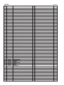
3$576
,7(0
12
'+'$/
&2'(12
12
86('
'(6&5,37,21
5(&,352&$7,1*%($5,1*
&2//$5
),567*($5
63$&(5
3,1,21
990
%$//%($5,1*99&36/
7$33,1*6&5(::)/$1*(';%/$&.
25,1*3
''0
%$//%($5,1*''&36/
$50$785($1'3,1,21$66·<'&9
0$*1(7
:$6+(5$
''0
%$//%($5,1*''&36/
635,1*
%586++2/'(5
&$5%21%586+$87267237<3(3$,5
386+,1*%87721
7$33,1*6&5(::)/$1*(';%/$&.
1$0(3/$7(
%$77(5<%6/(8523($861=/
+286,1*$%6(7
'&63(('&21752/6:,7&+
,17(51$/:,5(5('
,17(51$/:,5(%/$&.
+,7$&+,/$%(/
&21752//(57(50,1$/6(7
+($76,1.
6+,)7.12%
0$&+,1(6&5(:::$6+(560;
58%%(5+2/'(5
18703&6
*5,3&29(5
0$&+,1(6&5(:0;3&6
7$33,1*6&5(::)/$1*(';%/$&.
&86+,21$
5(0$5.6
,1&/8'
$/7(51$7,9(3$576
'+'$/
67$1'$5'$&&(6625,(6
,7(0
12
&2'(12
'(37+*$8*(
6,'(+$1'/(
&+$5*(502'(/8&<5/
3917
C$6(
1
A
12
86('
'(6&5,37,21
5(0$5.6
TECH. NEWS NO. 1574
237,21$/$&&(6625,(6
,7(0
12
&2'(12
+$00(5'5,//&+8&.6(700
&+8&.+$1'/(
58%%(5&$3
'5,//&+8&.$1'$'$37(56(7
&+8&.$'$37(5*6'63/86
'5,//&+8&.9/5%'
)/$7+'6&5(:$/()7+$1'0;
12
86('
'(6&5,37,21
&+8&.:5(1&+)259/%'9/5'
'5,//&+8&.9/''
&+8&.+$1'/(
'867&83
67233(5
= '5,9(5%,7$12/
= '5,9(5%,7$12/
$1&+256(77,1*$'$37(5$:µ0$18$/
$1&+256(77,1*$'$37(5$:µ0$18$/
$1&+256(77,1*$'$37(5$:µ0$18$/
$1&+256(77,1*$'$37(5$:µ0$18$/
$1&+256(77,1*$'$37(5$:µ0$18$/
$1&+256(77,1*$'$37(5%:µ0$18$/
$1&+256(77,1*$'$37(5%:µ0$18$/
$1&+256(77,1*$'$37(5%:µ0$18$/
$1&+256(77,1*$'$37(5%:µ0$18$/
$1&+256(77,1*$'$37(5%:µ0$18$/
&277(5
7$3(56+$1.$'$37(56'63/8612
$7$3(56+$1.$'$37(56'63/86
%7$3(56+$1.$'$37(56'63/86
&+8&.$'$37(5'6'63/86
$1&+256(77,1*$'$37(5$6'6:;/
$1&+256(77,1*$'$37(5$6'6:;/
$1&+256(77,1*$'$37(5$6'6:;/
$1&+256(77,1*$'$37(5$6'6:;/
$1&+256(77,1*$'$37(5%6'6:;/
$1&+256(77,1*$'$37(5%6'6:;/
$1&+256(77,1*$'$37(5%6'6:;/
$1&+256(77,1*$'$37(5%6'6:;/
&+(0,&$/$1&+25$'$37(56'600;/
&+(0,&$/$1&+25$'$37(56'600;/
&25(%,76+$1.6'63/8600/
&25(%,76+$1.6'63/8600/
$/7(51$7,9(3$576
5(0$5.6
,1&/8'
,1&/8'
,1&/8'
,1&/8'
'+'$/
237,21$/$&&(6625,(6
,7(0
12
&2'(12
12
86('
'(6&5,37,21
&25(%,76+$1.6'63/8600/
'867&2//(&725%$66·<
62&.(7$'$37(5%
7$3(56+$1.'5,//%,7';
7$3(56+$1.'5,//%,7';
7$3(56+$1.'5,//%,7';
7$3(56+$1.'5,//%,7';
7$3(56+$1.'5,//%,7';
7$3(56+$1.'5,//%,7';
7$3(56+$1.'5,//%,7';
&25(%,7$00
&25(%,7$00
&25(%,7$00
*8,'(3/$7()25&25(%,700
&25(%,7$00
*8,'(3/$7()25&25(%,700
&25(%,7$00
*8,'(3/$7()25&25(%,700
&25(%,7%00
*8,'(3/$7()25&25(%,700
&25(%,7%00
*8,'(3/$7()25&25(%,700
&(17(53,1$/)25&25(%,7'
&(17(53,1%/)25&25(%,7'
*5($6($)25+$00(5+$00(5'5,//*
*5($6()25+$00(5+$00(5'5,//*
*5($6()25+$00(5+$00(5'5,//*
%8//32,176'6005281'6+$1.7<3(
*5($6(02/8%$//2<12*
5(0$5.6
,1&/8'
,1&/8'
,1&/8'
,1&/8'
,1&/8'
,1&/8'
$/7(51$7,9(3$576
'+'$/
,7(0
12
&2'(12
'(6&5,37,21
12
86('
5(0$5.6
3ULQWHGLQ-DSDQ 1
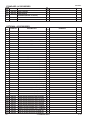
Hitachi Power Tools
/,6712*
(/(&75,&722/3$576/,67
&25'/(66527$5<+$00(5
0RGHO'+'/
(
3$576
,7(0
12
'+'/
&2'(12
12
86('
'(6&5,37,21
)5217&$3
67233(55,1*
*5,3
%$//+2/'(5
+2/'(53/$7(
+2/'(5635,1*
:$6+(5%
5(7$,1,1*5,1*)25'6+$)73&6
7$33,1*6&5(::)/$1*(';%/$&.
*($5&29(5
2,/6($/
6/((9(
''
%$//%($5,1*''36/
6/((9($
5(7$,1,1*5,1*00
67((/%$//'3&6
&</,1'(5
+,7$&+,3/$7(*5((1
7$33,1*6&5(:';
&+$1*(/(9(5
25,1*6
6(&21'*($5
635,1*$
:$6+(5$
5(7$,1,1*5,1*)25'6+$)7
6(&21'+$00(5
25,1*$3
+$00(5+2/'(5
25,1*%
'$03(5$
25,1*&
'$03(5+2/'(5
67233(55,1*
675,.(5
25,1*,'
3,6721
:$6+(5&
25,1*,'
,11(5&29(5$66·<
990
%$//%($5,1*99&36/
6(&21'6+$)7
:$6+(5%
&/87&+635,1*
&/87&+
3,67213,1
5(&,352&$7,1*%($5,1*
&2//$5
),567*($5
63$&(5
3,1,21
990
%$//%($5,1*99&36/
5(0$5.6
,1&/8'
$/7(51$7,9(3$576
3$576
,7(0
12
'+'/
&2'(12
'(6&5,37,21
12
86('
7$33,1*6&5(::)/$1*(';%/$&.
5(0$5.6
25,1*3
''0
%$//%($5,1*''&36/
$50$785($1'3,1,21$66·<'&9
,1&/8'
0$*1(7
:$6+(5$
''0
%$//%($5,1*''&36/
635,1*
%586++2/'(5
&$5%21%586+$87267237<3(3$,5
386+,1*%87721
7$33,1*6&5(::)/$1*(';%/$&.
1$0(3/$7(
%$77(5<%6/(8523($861=/
+286,1*$%6(7
'&63(('&21752/6:,7&+
,17(51$/:,5(5('
,17(51$/:,5(%/$&.
+,7$&+,/$%(/
&21752//(57(50,1$/6(7
+($76,1.
6+,)7.12%
0$&+,1(6&5(:::$6+(560;
58%%(5+2/'(5
18703&6
*5,3&29(5
0$&+,1(6&5(:0;3&6
7$33,1*6&5(::)/$1*(';%/$&.
&86+,21$
$/7(51$7,9(3$576
'+'/
67$1'$5'$&&(6625,(6
,7(0
12
&2'(12
12
86('
'(6&5,37,21
6,'(+$1'/(
'(37+*$8*(
&+$5*(502'(/8&<5/
A 39319
C$6(
1
5(0$5.6
TECH. NEWS NO. 1574
237,21$/$&&(6625,(6
,7(0
12
&2'(12
12
86('
'(6&5,37,21
+$00(5'5,//&+8&.6(700
&+8&.+$1'/(
58%%(5&$3
'5,//&+8&.$1'$'$37(56(7
&+8&.$'$37(5*6'63/86
'5,//&+8&.9/5%'
)/$7+'6&5(:$/()7+$1'0;
&+8&.:5(1&+)259/%'9/5'
'5,//&+8&.9/''
&+8&.+$1'/(
'867&83
67233(5
=
'5,9(5%,7$12/
=
'5,9(5%,7$12/
$1&+256(77,1*$'$37(5$:µ0$18$/
$1&+256(77,1*$'$37(5$:µ0$18$/
$1&+256(77,1*$'$37(5$:µ0$18$/
$1&+256(77,1*$'$37(5$:µ0$18$/
$1&+256(77,1*$'$37(5$:µ0$18$/
$1&+256(77,1*$'$37(5%:µ0$18$/
$1&+256(77,1*$'$37(5%:µ0$18$/
$1&+256(77,1*$'$37(5%:µ0$18$/
$1&+256(77,1*$'$37(5%:µ0$18$/
$1&+256(77,1*$'$37(5%:µ0$18$/
&277(5
7$3(56+$1.$'$37(56'63/8612
$7$3(56+$1.$'$37(56'63/86
%7$3(56+$1.$'$37(56'63/86
&+8&.$'$37(5'6'63/86
$1&+256(77,1*$'$37(5$6'6:;/
$1&+256(77,1*$'$37(5$6'6:;/
$1&+256(77,1*$'$37(5$6'6:;/
$1&+256(77,1*$'$37(5$6'6:;/
$1&+256(77,1*$'$37(5%6'6:;/
$1&+256(77,1*$'$37(5%6'6:;/
$1&+256(77,1*$'$37(5%6'6:;/
$1&+256(77,1*$'$37(5%6'6:;/
&+(0,&$/$1&+25$'$37(56'600;/
&+(0,&$/$1&+25$'$37(56'600;/
&25(%,76+$1.6'63/8600/
&25(%,76+$1.6'63/8600/
5(0$5.6
,1&/8'
,1&/8'
,1&/8'
,1&/8'
$/7(51$7,9(3$576
'+'/
237,21$/$&&(6625,(6
,7(0
12
&2'(12
12
86('
'(6&5,37,21
&25(%,76+$1.6'63/8600/
'867&2//(&725%$66·<
62&.(7$'$37(5%
7$3(56+$1.'5,//%,7';
7$3(56+$1.'5,//%,7';
7$3(56+$1.'5,//%,7';
7$3(56+$1.'5,//%,7';
7$3(56+$1.'5,//%,7';
7$3(56+$1.'5,//%,7';
7$3(56+$1.'5,//%,7';
&25(%,7$00
&25(%,7$00
&25(%,7$00
*8,'(3/$7()25&25(%,700
&25(%,7$00
*8,'(3/$7()25&25(%,700
&25(%,7$00
*8,'(3/$7()25&25(%,700
&25(%,7%00
*8,'(3/$7()25&25(%,700
&25(%,7%00
*8,'(3/$7()25&25(%,700
&(17(53,1$/)25&25(%,7'
&(17(53,1%/)25&25(%,7'
*5($6($)25+$00(5+$00(5'5,//*
*5($6()25+$00(5+$00(5'5,//*
*5($6()25+$00(5+$00(5'5,//*
%8//32,176'6005281'6+$1.7<3(
5(0$5.6
,1&/8'
,1&/8'
,1&/8'
,1&/8'
,1&/8'
,1&/8'
$/7(51$7,9(3$576
'+'/
,7(0
12
&2'(12
'(6&5,37,21
12
86('
5(0$5.6
3ULQWHGLQ-DSDQ 1
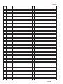
Hitachi Power Tools
/,6712*
(/(&75,&722/3$576/,67
&25'/(66527$5<+$00(5
0RGHO'+'$/
(
3$576
,7(0
12
'+'$/
&2'(12
12
86('
'(6&5,37,21
)5217&$3
67233(55,1*
*5,3
%$//+2/'(5
+2/'(53/$7(
+2/'(5635,1*
:$6+(5%
5(7$,1,1*5,1*)25'6+$)73&6
7$33,1*6&5(::)/$1*(';%/$&.
*($5&29(5$
2,/6($/
6/((9(
)(/73$&.,1*%
''
%$//%($5,1*''36/
6/((9($
5(7$,1,1*5,1*00
67((/%$//'3&6
&</,1'(5
+,7$&+,3/$7(*5((1
&+$1*(/(9(5$
25,1*6
)(/73$&.,1*
7$33,1*6&5(:';
67((/%$//'3&6
635,1*+
6(&21'*($5
635,1*$
:$6+(5$
5(7$,1,1*5,1*'
6(&21'+$00(5
25,1*$3
+$00(5+2/'(5
25,1*%
'$03(5$
25,1*&
'$03(5+2/'(5
67233(55,1*
675,.(5
25,1*,'
3,6721
:$6+(5&
25,1*,'
,11(5&29(5$66·<
6(&21'3,1,21
&/87&+635,1*
&/87&+
3,1,216/((9(
635,1*&
/2&.3/$7(
6(&21'6+$)7$
3,67213,1
5(0$5.6
,1&/8'
$/7(51$7,9(3$576
3$576
,7(0
12
'+'$/
&2'(12
12
86('
'(6&5,37,21
5(&,352&$7,1*%($5,1*
&2//$5
),567*($5
63$&(5
3,1,21
990
%$//%($5,1*99&36/
7$33,1*6&5(::)/$1*(';%/$&.
25,1*3
''0
%$//%($5,1*''&36/
$50$785($1'3,1,21$66·<'&9
0$*1(7
:$6+(5$
''0
%$//%($5,1*''&36/
635,1*
%586++2/'(5
&$5%21%586+$87267237<3(3$,5
386+,1*%87721
7$33,1*6&5(::)/$1*(';%/$&.
1$0(3/$7(
%$77(5<%6/(8523($861=/
+286,1*$%6(7
'&63(('&21752/6:,7&+
,17(51$/:,5(5('
,17(51$/:,5(%/$&.
+,7$&+,/$%(/
&21752//(57(50,1$/6(7
+($76,1.
6+,)7.12%
0$&+,1(6&5(:::$6+(560;
58%%(5+2/'(5
18703&6
*5,3&29(5
0$&+,1(6&5(:0;3&6
7$33,1*6&5(::)/$1*(';%/$&.
&86+,21$
5(0$5.6
,1&/8'
$/7(51$7,9(3$576
'+'$/
67$1'$5'$&&(6625,(6
,7(0
12
&2'(12
12
86('
'(6&5,37,21
5(0$5.6
6,'(+$1'/(
'(37+*$8*(
&+$5*(502'(/8&<5/
A 32919
C$6(
1 TECH. NEWS NO. 1574
237,21$/$&&(6625,(6
,7(0
12
&2'(12
+$00(5'5,//&+8&.6(700
,1&/8'
&+8&.+$1'/(
58%%(5&$3
'5,//&+8&.$1'$'$37(56(7
,1&/8'
&+8&.$'$37(5*6'63/86
'5,//&+8&.9/5%'
,1&/8'
)/$7+'6&5(:$/()7+$1'0;
12
86('
'(6&5,37,21
&+8&.:5(1&+)259/%'9/5'
'5,//&+8&.9/''
,1&/8'
&+8&.+$1'/(
'867&83
67233(5
= '5,9(5%,7$12/
= '5,9(5%,7$12/
$1&+256(77,1*$'$37(5$:µ0$18$/
$1&+256(77,1*$'$37(5$:µ0$18$/
$1&+256(77,1*$'$37(5$:µ0$18$/
$1&+256(77,1*$'$37(5$:µ0$18$/
$1&+256(77,1*$'$37(5$:µ0$18$/
$1&+256(77,1*$'$37(5%:µ0$18$/
$1&+256(77,1*$'$37(5%:µ0$18$/
$1&+256(77,1*$'$37(5%:µ0$18$/
$1&+256(77,1*$'$37(5%:µ0$18$/
$1&+256(77,1*$'$37(5%:µ0$18$/
&277(5
7$3(56+$1.$'$37(56'63/8612
$7$3(56+$1.$'$37(56'63/86
%7$3(56+$1.$'$37(56'63/86
&+8&.$'$37(5'6'63/86
$1&+256(77,1*$'$37(5$6'6:;/
$1&+256(77,1*$'$37(5$6'6:;/
$1&+256(77,1*$'$37(5$6'6:;/
$1&+256(77,1*$'$37(5$6'6:;/
$1&+256(77,1*$'$37(5%6'6:;/
$1&+256(77,1*$'$37(5%6'6:;/
$1&+256(77,1*$'$37(5%6'6:;/
$1&+256(77,1*$'$37(5%6'6:;/
&+(0,&$/$1&+25$'$37(56'600;/
&+(0,&$/$1&+25$'$37(56'600;/
&25(%,76+$1.6'63/8600/
&25(%,76+$1.6'63/8600/
$/7(51$7,9(3$576
5(0$5.6
'+'$/
237,21$/$&&(6625,(6
,7(0
12
&2'(12
12
86('
'(6&5,37,21
&25(%,76+$1.6'63/8600/
'867&2//(&725%$66·<
62&.(7$'$37(5%
7$3(56+$1.'5,//%,7';
7$3(56+$1.'5,//%,7';
7$3(56+$1.'5,//%,7';
7$3(56+$1.'5,//%,7';
7$3(56+$1.'5,//%,7';
7$3(56+$1.'5,//%,7';
7$3(56+$1.'5,//%,7';
&25(%,7$00
&25(%,7$00
&25(%,7$00
*8,'(3/$7()25&25(%,700
&25(%,7$00
*8,'(3/$7()25&25(%,700
&25(%,7$00
*8,'(3/$7()25&25(%,700
&25(%,7%00
*8,'(3/$7()25&25(%,700
&25(%,7%00
*8,'(3/$7()25&25(%,700
&(17(53,1$/)25&25(%,7'
&(17(53,1%/)25&25(%,7'
*5($6($)25+$00(5+$00(5'5,//*
*5($6()25+$00(5+$00(5'5,//*
*5($6()25+$00(5+$00(5'5,//*
%8//32,176'6005281'6+$1.7<3(
*5($6(02/8%$//2<12*
5(0$5.6
,1&/8'
,1&/8'
,1&/8'
,1&/8'
,1&/8'
,1&/8'
$/7(51$7,9(3$576
'+'$/
,7(0
12
&2'(12
'(6&5,37,21
12
86('
5(0$5.6
3ULQWHGLQ-DSDQ 1