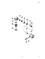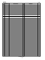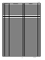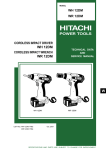
1
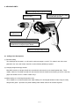
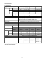
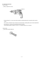
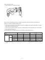
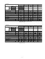
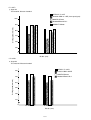
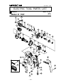
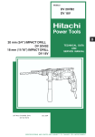
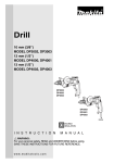
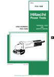
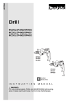
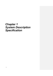
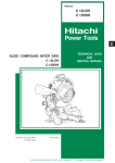
MODELS
10 mm DRILLS D 10VF
D 10VF
D 10VG
D 13VF
D 13VG
POWER TOOLS
D 10VG
D
13 mm DRILLS D 13VF
D 13VG
Except USA and Canada
LIST Nos. 0194, 0195, 0196, 0197
TECHNICAL DATA
AND
SERVICE MANUAL
Aug. 2001
SPECIFICATIONS AND PARTS ARE SUBJECT TO CHANGE FOR IMPROVEMENT
Notice for use
Specifications and parts are subject to change for improvement.
Refer to Hitachi Power Tool Technical News for further information.
CONTENTS
Page
1. PRODUCT NAME ........................................................................................................................... 1
2. MARKETING OBJECTIVE ............................................................................................................. 1
3. APPLICATIONS .............................................................................................................................. 1
4. SELLING POINTS .......................................................................................................................... 2
4-1. Selling Point Descriptions ............................................................................................................... 2
5. SPECIFICATIONS .......................................................................................................................... 3
5-1. Specifications .................................................................................................................................. 3
5-2. Optional Accessories ...................................................................................................................... 4
6. COMPARISONS WITH SIMILAR PRODUCTS .............................................................................. 6
6-1. Specification Comparisons ............................................................................................................. 6
6-2. Drilling Speed Comparisons ........................................................................................................... 8
7. PRECAUTIONS IN SALES PROMOTION ................................................................................... 10
7-1. Handling Instructions .................................................................................................................... 10
7-2. Caution Plate ................................................................................................................................ 10
7-3. Precautions on Usage ................................................................................................................... 11
7-4. Attaching Hook (A) ........................................................................................................................ 12
7-5. Attaching Angle Attachment Ass’y ................................................................................................. 13
8. PRECAUTIONS IN DISASSEMBLY AND REASSEMBLY .......................................................... 14
8-1. Disassembly ................................................................................................................................. 14
8-2. Reassembly .................................................................................................................................. 20
8-3. Wiring Diagram ............................................................................................................................. 21
8-4. Internal Wire Arrangement and Wiring Work ................................................................................ 22
8-5. Insulation Tests ............................................................................................................................. 24
8-6. No-Load Current Value ................................................................................................................. 24
9. STANDARD REPAIR TIME (UNIT) SCHEDULES ....................................................................... 25
For Model D 10VF ................................................................................................................................ 25
For Models D 10VG, D 13VF and D13VG ........................................................................................... 26
Assembly Diagram for D 10VF ............................................................................................................ 27
Assembly Diagram for D 10VG ............................................................................................................ 31
Assembly Diagram for D 13VF ............................................................................................................ 35
Assembly Diagram for D 13VG ............................................................................................................ 41
1. PRODUCT NAME
Hitachi 3/8" (10 mm) Drills, Model D 10VF
Model D 10VG
Hitachi 1/2" (13 mm) Drills, Model D 13VF
Model D 13VG
2. MARKETING OBJECTIVE
The new drill series Models D 10VF, D 10VG, D 13VF and D 13VG have the high torque, powerful motor and
attractive ergonomic-design as its main design concept.
This drill series is divided into two groups according to the drill chuck capacities. The Models D 10VF and
D 10VG have the drill chuck capacity of 3/8" (10 mm) and the Models D 13VF and D 13VG have the drill chuck
capacity of 1/2" (13 mm). Each drill is provided with the function to select switch the drilling speed between HIGH
and LOW, and is selectable either keyless chuck type or keyed chuck type to meet various market demands.
The outstanding features are as follows:
(1) Powerful high performance motor
(2) Uniquely designed soft grip handle
(3) Sturdy aluminum gear cover and inner cover
(4) Large 2-finger sized trigger switch
Hook (A) and the angle attachment ass’y (D 13VF and D 13VG only) are available as optional accessories.
3. APPLICATIONS
Drilling into metal, wood and plastic
--- 1 ---
4. SELLING POINTS
Powerful drilling with the powerful motor
Sturdy aluminum gear cover
and inner cover
Uniquely designed soft grip handle
for comfortable operation
Sturdy drill chuck
for industrial use
Motor cooling air is discharged toward the front
Easy-to-operate 2-finger sized trigger switch and
forward/reverse changeover push button
Powerful and unique body design
4-1. Selling Point Descriptions
(1) Powerful drilling
The rated input of the motor is 710 W, and its maximum output is 750 W. This motor is one of the most
powerful in the class and various materials can be efficiently drilled by its power.
(2) Uniquely designed soft grip handle
Most drills featuring a soft grip handle are covered with soft materials at the handle portion only. These
models, however, are widely covered with soft materials from the handle to the housing to ensure a non-slip
grip of the handle even if it is held in various ways.
(3) Motor cooling air is discharged toward the front
These models are so constructed that the motor cooling air is discharged toward the front using the newly
designed fan guide. Operators can perform drilling work without concern for the discharged air.
--- 2 ---
5. SPECIFICATIONS
5-1. Specifications
D 10VF
D 10VG
D 13VF
D 13VG
Twist bit
10 mm (3/8")
10 mm (3/8")
13 mm (1/2")
13 mm (1/2")
Hole saw
NA
38 mm (1-1/2")
51 mm (2")
70 mm (2-3/4")
25 mm (1")
32 mm (1-1/4")
40 mm (1-9/16")
40 mm (1-9/16")
Auger bit
NA
NA
32 mm (1-1/4")
38 mm (1-1/2")
Hole saw
29 mm (1-1/8")
70 mm (2-3/4")
102 mm (4")
114 mm (4-1/2")
Model
Capacities Steel
Wood
Drill chuck
Flat spade bit
UNF 1/2" - 20
Mount type
Capacity
0.8 mm --- 10 mm (1/32" --- 3/8")
1.5 mm --- 13 mm (1/16" --- 1/2")
AC single phase series commutator motor
Type of motor
Enclosure
Housing and handle: Glassfiber reinforced polyamide resin
Grip cover: Glassfiber reinforced polypropylene resin + elastomer
Gear cover and inner cover: Aluminum alloy die casting
Type of switch
Variable speed control trigger switch with reversing switch
Power source
AC single phase 50/60 Hz
(110, 220, 230, 240 V)
Rated voltage (by areas)
710 W*1
Power input
Power output
Speed
Weight
Full-load
380 W
Max.
750 W
No-load
0 --- 3,000/min.
0 --- 1,200/min.
0 --- 850/min.
0 --- 600/min.
Full-load
1,840/min.
790/min.
620/min.
380/min.
1.8 kg
1.9 kg
2.1 kg
2.1 kg
keyed chuck Gross
3.4 kg
3.5 kg
3.7 kg
3.7 kg
with
1.8 kg
1.9 kg
2.0 kg
2.0 kg
3.4 kg
3.5 kg
3.6 kg
3.6 kg
with
Net (without cord)
Net (without cord)
keyless chuck Gross
Packaging
Plastic case (in corrugated cardboard sleeve)
2-core cabtire cord 2.5 m
Cord
Standard accessories
2
Chuck wrench• • • 1* Side handle • • • 1
Plastic case • • • 1
Side handle • • • 1
Side handle • • • 1
Chuck wrench• • • 1*2 Chuck wrench• • • 1*2 Handle joint • • • 1
Plastic case • • • 1
Plastic case • • • 1
Chuck wrench• • • 1*2
Plastic case • • • 1
*1 Power input is subject to change by areas.
*2 Spec. only for the keyed chuck.
--- 3 ---
5-2. Optional Accessories
<For all models>
Hook (A) (Code No. 317676)
Hook (A)
* To attach Hook (A), it is necessary to disassemble the handle portion which covered the tool's electrical
system.
For customers continued safety and electrical shock protection, installing Hook (A) on this drill should ONLY
be performed by a HITACHI AUTHORIZED SERVICE CENTER.
For attaching procedure of Hook (A), refer to "7-4. Attaching Hook (A)" in this manual.
<For D 10VF>
Side handle (Code No.981205)
--- 4 ---
<For D 13VF and D 13VG>
Angle attachment ass'y (Code No. 319528)
Used extensively for drilling between joints, studding, in tight corners or in close quarters on machinery and
equipment. Provides two additional drilling speeds.
Chuck transferred from drill to LOW spindle of angle unit, the drilling speed is decreased to about 70% and the
drilling torque increased to about 150%.
Chuck transferred to HIGH spindle of angle unit, the drilling speed is increased to about 150% and the drilling
torque decreased to about 70%.
The table below shows the drilling capacities when attaching the angle attachment ass'y.
Model
D 13VF
LOW (650/min.) HIGH (1350/min.) LOW (400/min.)
Speed of angle unit
Capacities
Steel
D 13VG
HIGH (900/min.)
Twist bit
13 mm (1/2")
13 mm (1/2")
13 mm (1/2")
13 mm (1/2")
Hole saw
64 mm (2-1/2")
32 mm(1-1/4" )
70 mm (2-3/4")
51 mm (2")
40 mm (1-9/16")
32 mm (1-1/4")
40 mm (1-9/16")
40 mm (1-9/16")
38 mm(1-1/2" )
29 mm (1-1/8")
38 mm(1-1/2" )
32 mm (1-1/4")
64 mm (2-1/2")
114 mm (4-1/2")
102 mm (4")
Wood Flat spade bit
Auger bit
Hole saw
114 mm(4-1/2" )
For attaching procedure of the angle attachment ass'y, refer to "7-5. Attaching Angle Attachment Ass'y" in this
manual.
--- 5 ---
6. COMPARISONS WITH SIMILAR PRODUCTS
6-1. Specification Comparisons
< D 10VF >
HITACHI
D 10VF
10 (3/8")
NR
25 (1")
NR
70 (2-3/4")
710*1
0 - 3000
750
16.8
78.0
Single
Aluminum
mm (in. )
Capacities Steel Twist bit
Hole saw
Wood Flat spade bit mm (in. )
Auger bit
Hole saw
W
Rated power input
/min.
No-load speed
W
Max. power output
Nm
Max. torque
dB
No-load sound pressure level
Gear train
Material of gear cover
Soft grip handle
Two-finger trigger
Optional
Side handle
Keyed Keyless
Type of drill chuck
Spindle lock
mm
263
Overall length
265
1.8
1.8
kg
Net weight
BOSCH
GBM10RE
10
MAKITA
6480
10
METABO
BE560
10
DEWALT
DW221
10
25
25
20
25
450
0 - 2200
480
0 - 2500
560
0 - 2800
701
0 - 2500
6.0
13.8
Single
Plastic
Single
Plastic
Single
Plastic
Double
Aluminum
Optional
Keyless
Keyless
Optional
Keyless
Keyless
1.7
1.6
279
261
1.4
1.4
*1 Power
input is subject to change by areas.
*2 Factory test result
< D 10VG >
HITACHI
D 10VG
10 (3/8")
38 (1-1/2")
32 (1-1/4")
NR
29 (1-1/8")
710*1
0 - 1200
750
38.9
78.0
Double
Aluminum
mm (in. )
Capacities Steel Twist bit
Hole saw
Wood Flat spade bit mm (in. )
Auger bit
Hole saw
W
Rated power input
/min.
No-load speed
W
Max. power output
Nm
Max. torque
dB
No-load sound pressure level
Gear train
Material of gear cover
Soft grip handle
Two-finger trigger
Side handle
Keyed
Type of drill chuck
Spindle lock
mm
276
Overall length
kg
Net weight
1.9
BOSCH
GBM10-2RE
10/6
MAKITA
DP3002 DP3003
10
DEWALT
DW226
10
25/15
32
30
500
0 - 1150/0 - 2100
710
0 - 1200
670*2
36.0
78.3*2
Double
Aluminum
701
0 - 1200
9.5/5.0
80.4*2
Double (2-speed)
Plastic
Keyless
Keyless
Keyed
278
309
304
296
1.9
1.8
2.0
1.8
*1 Power input is subject to change by areas.
*2 Factory test result
--- 6 ---
Keyless
27.1
Double
Aluminum
Keyless
1.9
< D 13VF >
HITACHI
D 13VF
13 (1/2")
51 (2")
40 (1-9/16")
32 (1-1/4")
102 (4")
710*1
0 - 850
750
50.0
78.0
Double
Aluminum
mm (in. )
Capacities Steel Twist bit
Hole saw
Wood Flat spade bit mm (in. )
Auger bit
Hole saw
W
Rated power input
/min.
No-load speed
W
Max. power output
Nm
Max. torque
dB
No-load sound pressure level
Gear train
Material of gear cover
Soft grip handle
Two-finger trigger
Side handle
Keyed Keyless
Type of drill chuck
Spindle lock
mm
287
Overall length
290
2.1
2.0
kg
Net weight
BOSCH
GBM13-2RE
13/8
DP4000 DP4001
13
METABO
BE532S-R+L
13
DEWALT
DW236
13
32/20
38
30
30
550
520
0 - 1000
701
0 - 850
Plastic
750
0 - 900
750*2
51.0
78.9*2
Triple
Aluminum
78.4*2
Double
Aluminum
35.8
83.5*2
Double
Aluminum
Keyless
Keyed Keyless
Keyless
Keyless
0 - 1000/0 - 1900
11.5/6.0
81.9*2
Double (2-speed)
MAKITA
332
304
308
294
2.0
2.2
2.0
1.7
1.9
*1 Power
input is subject to change by areas.
*2 Factory test result
< D 13VG >
HITACHI
D 13VG
13 (1/2")
70 (2-3/4")
40 (1-9/16")
38 (1-1/2")
114 (4-1/2")
710*1
0 - 600
750
78.7
78.0
Double
Aluminum
mm (in. )
Capacities Steel Twist bit
Hole saw
Wood Flat spade bit mm (in. )
Auger bit
Hole saw
W
Rated power input
/min.
No-load speed
W
Max. power output
Nm
Max. torque
dB
No-load sound pressure level
Gear train
Material of gear cover
Soft grip handle
Two-finger trigger
Side handle
Keyed Keyless
Type of drill chuck
Spindle lock
mm
287
Overall length
290
2.1
2.0
kg
Net weight
BOSCH
GBM13HRE
13
DP4002 DP4003
13
METABO
BE622S-R+L
16
DEWALT
DW246
13
40
38
40
30
550
0 - 550
750
0 - 600
750*2
73.0
78.9*2
Triple
Aluminum
620
0 - 550
701
0 - 600
79.6*2
Triple
Aluminum
Triple
Aluminum
Keyed Keyless
Keyed
Keyless
40.0
81.9*2
Triple
Plastic
Keyed
MAKITA
295
304
308
291
2.1
2.2
2.0
2.1
*1 Power input is subject to change by areas.
*2 Factory test result
--- 7 ---
57.3
2.0
6-2. Drilling Speed Comparisons
Drilling speed depends on the operating conditions. The following test results are based on actual factory tests,
and should be used as a reference only.
< D 10VF>
Flat spade bit
Test material: Western hemlock Thrust: 196 N
HITACHI D 10VF
1000
BOSCH GBM10-2RE (High speed gear)
Drilling speed (mm/min.)
900
800
700
600
500
0
20 mm dia.
25 mm dia.
Bit dia. (mm)
< D 10VG>
Flat spade bit
Test material: Western hemlock Thrust: 196 N
HITACHI D 10VG
700
BOSCH GBM 10-2 RE (Low speed gear)
Drilling speed (mm/min.)
MAKITA DP3003
600
500
400
300
200
0
25 mm dia.
30 mm dia.
Bit dia. (mm)
--- 8 ---
< D 13VF>
Auger bit
Test material: Western hemlock
HITACHI D 13VF
BOSCH GBM 13-2 RE (Low speed gear)
1000
MAKITA DP4001
Metabo BE532S-R+L
DEWALT DW236
Drilling speed (mm/min.)
900
800
700
600
500
0
22 mm dia.
32 mm dia.
Bit dia. (mm)
< D 13VG>
Auger bit
Test material: Western hemlock
HITACHI D 13VG
600
BOSCH GBM 13HRE
MAKITA DP4003
Metabo BE622S-R+L
Drilling speed (mm/min.)
500
400
300
200
100
0
25 mm dia.
36 mm dia.
Bit dia. (mm)
--- 9 ---
7. PRECAUTIONS IN SALES PROMOTION
In the interest of promoting the safest and most efficient use of the Models D 10VF, D 10VG, D 13VF and D 13VG
Drills by all of our customers, it is very important that at the time of sales the salesperson carefully ensures that
the buyer seriously recognizes the importance of the contents of the Handling Instructions, and fully understands
the meaning of the precautions listed on the Caution Plate attached to each tool.
7-1. Handling Instructions
Although every effort is made in each step of design, manufacture and inspection to provide protection against
safety hazards, the dangers inherent in the use of any electric power tool cannot be completely eliminated.
Accordingly, general precautions and suggestions for the use of electric power tools, and specific precautions
and suggestions for the use of the Drills are listed in the Handling Instructions to enhance the safe, efficient use of
the tool by the customer. Salespersons must be thoroughly familiar with the contents of the Handling Instructions
to be able to offer appropriate guidance to the customer during sales promotion.
7-2. Caution Plate
The following basic safety precautions are listed on the Caution Plate attached to the main body of each tool.
These precautions are not listed on the Name Plates of the products destined for Europe.
--- 10 ---
7-3. Precautions on Usage
Ring
(1) Keyless chuck
Sleeve
1 Mounting of the bit
Open the chuck jaws, and insert the bit into the
chuck. To open the chuck jaws, hold the ring while
Loosen
turning the sleeve in the counterclockwise direction
(viewed from the front side).
Tighten
Firmly grasp the ring and turn the sleeve in the
Fig. 1
clockwise direction. Tighten securely. (Fig. 1)
2 Dismounting of the bit
To remove the bit, firmly grasp the ring and turn the
sleeve in the counterclockwise direction. (Fig. 1)
If it is hard to loosen the sleeve, fix the spindle using
the open-end wrench, hold the sleeve firmly, and turn
it in the loosening direction (counterclockwise when
viewed from the front). (Fig. 2)
Loosen
Open-end
wrench
Fig. 2
(2) Side handle
For D 10VG and D 13VF
A side handle is supplied with drill.
It can be installed on either side of the tool for right or
left handed use.
To install the side handle, thread it into the socket on
the desired side of the tool and tighten it securely.
Spindle
Tighten
Loosen
(Fig. 3)
For D 13VG
Fig. 3
A side handle and a handle joint are supplied with drill.
The large torque of the motor for this drill can result in
considerable reaction to your arms during drilling work.
Accordingly, make absolutely sure before use that the
side handle and the handle joint are completely
installed. (Fig. 4)
Handle
joint
Loosen
Tighten
Loosen
Fig. 4
--- 11 ---
Side
handle
Tighten
7-4. Attaching Hook (A)
The numbers in the descriptions below correspond to the item numbers in the Parts List and exploded assembly
diagram. The Bold numbers are for the Model D 10VF, the Bold numbers for the Model D 10VG, the [Bold]
numbers for the Model D 13VF, and the <Bold> numbers for the Model D 13VG.
(1) Loosen the Screws (Plastic Tie) D4 x 25 27 31 [31] <31>, and remove the Grip Cover 26 30 [30] <30>.
(2) Loosen the Tapping Screws (W/Flange) D4 x 35 24 28 [28] <28>, Tapping Screw (W/Flange) D4 x 20
(Black) 25 29 [29] <29>, and remove Handle (A) 29 33 [33] <33>.
(3) Insert the mounting foot of Hook (A) into the air vent
of Handle (B) 23 27 [27] <27> as shown in Figs. 6 and 7.
(4) Mount Handle (A) 29 33 [33] <33> and the Grip Cover
26 30 [30] <30>.
Hook (A)
Handle (B)
23 27 [27] <27>
Refer to "8-2-3. Tightening torque" for tightening
torque of each screw. Be careful not to catch the
internal wires when mounting Handle (A).
Fig. 5
Enlarged view of "A" portion
Handle (B)
23 27 [27] <27>
Mounting foot of Hook (A)
Fig. 6
Hook (A)
Fig. 7
--- 12 ---
7-5. Attaching Angle Attachment Ass’y
(1) Removing the drill chuck from drill (Refer to section 8-1-2.)
(2) Attaching the angle unit
After removing the chuck, engage the coupling to the
drill spindle. Fit the joint sleeve to the gear cover,
Angle
unit
Joint
sleeve
Coupling
attach the angle unit to the other end of the joint sleeve,
and turn the angle unit slightly in either direction so the
hex. hole in the coupling engages the hex. portion of
the angle unit spindle. Adjust the direction of the angle
unit and tighten the joint sleeve by clamping bolts.
Tighten two clamping bolts equally and gradually in turn
Clamping bolt
Fig. 8
with a torque of 6.86--- 7.84 N•m (extent of force which
can be subjected by only a wrist with the open end
wrench provided to tighten clamping bolts). (Fig. 8)
To operate the angle unit at low speed, attach the chuck
Low speed
to the angle unit spindle at the side marked "LOW" and
secure the locking screw. At this setting, the drilling
speed is decreased to about 70% and the drilling torque
increased to about 150%. (Fig. 9)
Fig. 9
To operate the angle unit at high speed, attach the
chuck to the angle unit spindle at the side marked
"HIGH" and secure the locking screw. At this setting,
the drilling speed is increased to about 150% and the
High speed
drilling torque decreased to about 70%. (Fig. 10)
(3) Installing the side handle (Fig. 11)
The side handle can be installed on either side of the
angle unit for right or left handed use. To install the
side handle, thread it into the socket on the desired side
Fig. 10
of the angle unit and tighten it securely.
Refer to section 8-1-4 for removal of the drill chuck from
the angle unit.
Side handle
Fig. 11
--- 13 ---
8. PRECAUTIONS IN DISASSEMBLY AND REASSEMBLY
The numbers in the descriptions below correspond to the item numbers in the Parts List and exploded assembly
diagram. The Bold numbers are for the Model D 10VF, the Bold numbers for the Model D 10VG, the [Bold]
numbers for the Model D 13VF, and the <Bold> numbers for the Model D 13VG.
8-1. Disassembly
8-1-1. Motor section disassembly
(1) Removal of the grip cover
Loosen the Screws (Plastic Tie) D4x25 27 31 [31] <31>, and remove the Grip Cover 26 30 [30] <30>.
(2) Removal of the handle
Loosen the Tapping Screws (W/Flange) D4 x 35 24 28 [28] <28> and the Tapping Screw (W/Flange)
D4 x 20 (Black) 25 29 [29] <29>, and remove Handle (A) 29 33 [33] <33> and Handle (B) 23 27 [27]
<27>.
Housing
21 25 [25] <25>
(3) Removal of the carbon brushes
Using a small-diameter bar, push the Brush Holders 30 34
[34] <34> out of the hole at the lower portion of the Housing
21 25 [25] <25>. (Fig. 12)
Then, while pushing the Carbon Brushes 32 36 [36] <36>
to the bottom of the Brush Holders, gently pull out
and disconnect the internal wire terminals.
(See Figs. 13 and 14.)
Hole
Fig. 12
Terminal
Carbon brush
stop piece
Carbon brush
stop piece
Pull out
Carbon brush
32 36 [36] <36>
Terminal
Brush holder
30 34 [34] <34>
Projection
Push
Fig. 14
Fig. 13
--- 14 ---
8-1-2. Removal of the drill chuck
The Drill Chuck 4
4 [4] <4> is secured to the Spindle 5
Special Screw (Left Hand) M6 x 23 1
5 [5] <5> with 1/2"-20UNF (Right Hand) and the
1 [1] <1>. At first, open the chuck jaw as far as possible and loosen
the Special Screw by turning it clockwise.
a. Hold the drill so that only the Drill Chuck 4
4 [4] <4> rest firmly and squarely on the edge of a solid bench.
Install the hex. bar wrench into the Drill Chuck. Turn the Drill Chuck until the wrench is at about a 30˚ angle to
the bench top and strike the wrench sharply with a hammer so the drill chuck turns in the counterclockwise
direction. (Fig. 15)
Special Screw (Left Hand) M6 x 23
1 1 [1] <1>
Hex. bar wrench
Loosen
Fig. 15
If the Drill Chuck cannot be removed by striking the wrench, do not strike the wrench forcibly and try another
way as follows.
b. Hold the Spindle 5
5 [5] <5> with the open-end wrench secured to the vise as shown in Fig. 16.
Mount the pipe to the hex. bar wrench. Turn the hex. bar wrench counterclockwise to loosen the drill chuck.
(Fig. 16)
Pipe
Turn it counterclockwise.
Hex. bar wrench
Vise
Open-end wrench
Fig. 16
--- 15 ---
c. (For keyed chuck only)
Secure the drill chuck with a disassembly tool: Ring Ass'y and Ring (for 10 mm drill chuck: J-90, ring Code No.
970833, ring ass'y Code No. 970832) (for 13 mm drill chuck: J-78, ring Code No. 970818, ring ass'y Code No.
970817) to the drill chuck, which in proper sequence should be secured with a vise. Then fit a disassembly
tool: Wrench Ass'y (J-140, Code No. 970921) to the spindle, and turn it counterclockwise to loosen the drill
chuck. (Fig. 17)
Turn it counterclockwise.
Ring Ass'y and Ring
for 10 mm drill chuck: J-90
for 13 mm drill chuck: J-78
Wrench Ass'y (J-140)
Vise
Drill chuck
Fig. 17
8-1-3. Gear cover section disassembly
(1) Removal of the second pinion (except the Model D 10VF)
Second Pinion 13 [13] <13> can be removed by tapping the end of Gear Cover (A) 10 [10] <10>.
(2) Disassembly of the second pinion
Place the end surface of the First Gear 14 [14] <14> on a tubular jig and press down on the Second Pinion
13 [13] <13> with a hand press. (Fig. 18)
< CAUTION > Be sure to replace both the second pinion and the first gear with new ones.
Push
First Gear
14 [14] <14>
Second Pinion
13 [13] <13>
Fig. 18
--- 16 ---
(3) Removal of the spindle
Remove the Retaining Ring 6
6 [6] <6>. Place the end surface of the Gear Cover 10 10 [10] <10> on
the cylindrical jig and press down on the Spindle 5
5 [5] <5> with a hand press. Then the Spindle can be
removed together with the Ball Bearing 6002VVCMPS2L 7
7 [7] <7> and the Retaining Ring 8
8 [8]
<8>. The Gear 11 or the Final Gear 12 [12] <12> can be removed from the Spindle.
(Figs. 19 and 20)
<CAUTION> Be sure to replace both the spindle and the gear or the final gear with new ones.
Push
Push
Spindle (B) 5
Spindle (A) 5 [5] <5>
Final Gear
12 [12] <12>
Gear 11
Gear Cover (B) 10
Gear Cover (A)
10 [10] <10>
33 mm dia.
33 mm dia.
Model D 10VF
Models D 10VG, D 13VF and D 13VG
Fig. 19
Fig. 20
(4) Removal of the gear cover and the inner cover from the housing
Loosen the Tapping Screws D5 9
9 [9] <9>, 12 16 [16] <16> and separate the Gear Cover 10 10
[10] <10>. Then, remove the Inner Cover 13 17 [17] <17> together with the Armature Ass'y 15 19 [19]
<19> from the Housing 21 25 [25] <25>.
--- 17 ---
(5) Removal of the armature ass'y from the inner cover
As illustrated in Fig. 21, support the Inner Cover 13 17 [17] <17> with a tubular jig, and push down on the
top of the pinion of the Armature Ass'y 15 19 [19] <19>.
Push
Pinion
Inner Cover
13 17 [17] <17>
Armature Ass'y
15 19 [19] <19>
65 mm to 70 mm dia.
Fig. 21
(6) Removal of the stator from the housing
First, disconnect the internal wires from the Switch 35 39 [39] <39>. To disconnect the internal wires from
switch, insert a small flat-blade screwdriver into the windows near the terminals and pull out the internal wires.
Remove the Hex. Hd. Tapping Screws D4 x 55 17 21 [21] <21> and tap the end surface of the Housing 21
25 [25] <25> slightly with a wooden hammer. Then the stator can be removed from the housing.
--- 18 ---
8-1-4. Angle attachment ass'y (optional accessory) disassembly
(1) Removal of the drill chuck from the angle unit
The drill chuck can be removed from angle unit in the same manner it was removed from the drill; however,
always remove angle unit from the drill before attempting to remove the drill chuck. This will prevent damage
of drills gear. Use the Wrench [614] <614> (open-end) provided to hold the angle unit spindle before
attempting to remove the drill chuck. (Fig. 22)
Wrench
[614] <614>
Special Screw
[1] < 1 >
Hex. bar wrench
Loosen
Fig. 22
If the drill chuck cannot be removed by striking the hex. bar wrench, do not strike the hex. bar wrench forcibly.
Remove the drill chuck according to the procedure specified in section 8-1-2.
(2) Removal of gears and spindles from the angle unit
Remove the Retaining Rings [605] <605>, then tap the end of the Angle Head Ass'y [612] <612> to take out
the spindle pinion ass'y and the Spindle and Gear Set [613] <613>.
To remove the Pinion [603] <603> and the Ball Bearing [604] <604> from the Spindle [607] <607>, place the
end surface of the Ball Bearing [604] <604> on a tubular jig and press down on the Spindle [607] <607> with a
hand press. (Fig. 23)
Push
Spindle
[607] <607>
Pinion
[603] <603>
Woodruff Key
[606] <606>
Ball Bearing
[604] <604>
Fig. 23
--- 19 ---
8-2. Reassembly
Reassembly can be accomplished by following the disassembly procedures in reverse. However, special
attention should be given to the following items.
8-2-1. Internal wire arrangement
(1) Arrange the internal wires according to "8-4 Internal Wire Arrangement and Wiring Work".
(2) Be careful not to catch the internal wires when mounting Handle (A).
8-2-2. Lubrication
(1) Apply SEP-3A Grease to the following portions.
< For Model D 10VF >
Teeth of the Armature Ass'y 15 (with a brush)
Teeth of the Gear 11
Metal portion of the Inner Cover 13
Inside of Gear Cover (B) 10 : 5 g
< For Models D 10VG, D 13VF and D 13VG >
Teeth of the Armature Ass'y
19 [19] <19>
Teeth of the First Gear
14 [14] <14>
Second Pinion
13 [13] <13>
Final Gear
12 [12] <12>
Metal portion of the Inner Cover 17 [17] <17>
Inside of Gear Cover (A) 10 [10] <10> : 15 g
(2) For the angle attachment ass'y ... Optional accessory
Apply Motor Grease No. 29 to the following portions.
Inside of the Angle Head Ass'y [612] <612> : 15 g
8-2-3. Tightening torque
(1) Special Screw (Left Hand) M6 1
1 [1] <1>
• • • • • • • • • • • • • • • • • • • • • • • • • •
3.92 to 5.88 N•m
(2) Tapping Screw D4 24 25 36 [28] [29] [40]
[28] [29] [40] <28> <29> <40>
(3) Screw (Plastic Tie) D4 27 31 [31] <31>
(4) Tapping Screw D5 9 12
(5) Drill Chuck 4
4 [4] <4>
• • • • • • • • • • • • • • • • • • • • •
1.47 to 2.45 N•m
•••••••• • • • • • • • • • • • • • • • • • • • • • • • • • •
1.47 to 2.45 N•m
9 16 [9] [16] <9> <16>
••••••••••••••••••••••••••••• • • • • • • • • • • • • • • • • • • • • • • • • •
(6) Machine Screw M3 (Switch 35 39 [39] <39>)
(7) Bolt M8 [610] <610>
• • • • • • • • • • • • • • • • •
• • • • • • • • • • • • • • • • • • • • • • • • • •
•••••••••••••••••••••••••••••••••••••• • • • • • •••••••••••••••••••••
(For the Angle Attachment Ass'y
•••••••••••
Optional accessory)
--- 20 ---
2.45 to 3.43 N•m
29.4 to 39.2 N•m
0.39 to 0.78 N•m
6.86 to 7.84 N•m
8-3. Wiring Diagram
Models D 10VF, D 10VG, D 13VF and D 13VG
D 10VF: Blue
Other models: Brown
Stator
Choke coil
Black or brown
Gray
White
Armature
Cord
Noise
suppressor
Black
Stator
Red
White or blue
Choke coil
Speed control switch
Reversing switch
D 10VF: Brown
Other models: Blue
Fig. 24
--- 21 ---
8-4. Internal Wire Arrangement and Wiring Work
A. Internal wire arrangement
Brush terminal (Choke coil)
Carbon brush
Brown
(Choke coil)
Neutral conductor
(Noise suppressor)
Blue
(Choke coil)
Put the neutral conductor
of the noise suppressor
around the boss with a
minimum of slack.
Put the choke coil over the ribs of the handle.
Ribs
D 10VF: Blue
Others: Brown
(Choke coil)
White (Stator)
Red (Stator)
Gray (Stator)
D 10VF: Blue
Others: Brown
Neutral conductor
(Noise suppressor)
Black
(Stator)
Black or brown
(Cord)
White or blue
(Cord)
White
(Stator)
Noise suppressor
Fig. 25
--- 22 ---
B. Switch connection
(1) Wiring of reversing switch
<D 10VF>
Black
(Stator)
Brown
(Choke coil)
White
(Stator)
Blue
(Choke coil)
Fig. 26
<D 10VG, D 13VF, D 13VG>
Black
(Stator)
Blue
(Choke coil)
White
(Stator)
Brown
(Choke coil)
Fig. 27
(2) Wiring of speed control switch
Red (Stator)
Gray (Stator)
Black or brown
(Stator)
White or blue
(Cord)
Noise
suppressor
Fig. 28
--- 23 ---
8-5. Insulation Tests
On completion of reassembly after repair, measure the insulation resistance and conduct the dielectric strength
test.
Insulation resistance: 7 MΩ or more with DC 500 V Megohm Tester
Dielectric strength: AC 4,000 V/1 minute, with no abnormalities 220 V --- 240 V (and 110 V for U.K. products)
AC 2,500 V/1 minute, with no abnormalities 110 V --- 127 V (except U.K. products)
8-6. No-Load Current Value
After no-load operation for 30 minutes, the no-load current value should be as follows.
Voltage (V)
110
220
230
240
Current (A) Max.
3.0
2.0
2.0
2.0
--- 24 ---
9. STANDARD REPAIR TIME (UNIT) SCHEDULES
For Model D 10VF
MODEL
Variable
Fixed
10
20
30
Work Flow
D 10VF
Housing
Stator
Handle (A)
Handle (B)
Switch
Cord
Pushing Button
Carbon Brush
x 2 pcs.
General Assembly
Armature Ass'y
Ball Bearing
(608VV)
Ball Bearing
(608DD)
Inner Cover
Gear Cover
(B)
Gear
Spindle (B)
Ball Bearing
(6002VV)
--- 25 ---
40
50
60 min.
For Models D 10VG, D 13VF and D 13VG
MODEL
Variable
Fixed
10
20
30
Work Flow
D 10VG
D 13VF
D 13VG
Housing
Stator
Handle (A)
Handle (B)
Switch
Cord
Pushing Button
Carbon Brush
x 2 pcs.
General Assembly
Armature Ass'y
Ball Bearing
(608VV)
Ball Bearing
(608DD)
Inner Cover
Second Pinion
First Gear
Ball Bearing
(627VV)
Ball Bearing
(606ZZ)
Gear Cover (A)
Final Gear
Spindle (A)
Ball Bearing
(6002VV)
--- 26 ---
40
50
60 min.
LIST NO. 0194
ELECTRIC TOOL PARTS LIST
DRILL
Model D 10VF
2001• 8 • 21
(E2)
3
1
2
4
5
6
7
4
8
9
10
13
14
11
15
12
16
17
18
19
20
21
22
23
24
28
26
33
30
25
501
29
31
32
34
27
35
41
38
39
37
36
--- 27 ---
40
PARTS
ITEM
NO.
1
D 10VF
NO.
USED
CODE NO.
DESCTIPTION
311-959
SPECIAL SCREW (LEFT HAND) M6X23
1
2
319-529
CHUCK WRENCH 10VLR-J
1
3
950-288
VINYL BAND
1
*
4
319-342
DRILL CHUCK 10VLR-J
1
*
4
319-343
DRILL CHUCK 10VLRD-N (W/O CHUCK WRENCH)
1
5
319-335
SPINDLE (B)
1
6
948-001
RETAINING RING FOR D32 HOLE
1
7
600-2VV
BALL BEARING 6002VVCMPS2L
1
8
939-544
RETAINING RING FOR D15 SHAFT (10 PCS.)
1
9
317-449
TAPPING SCREW (W/FLANGE) D5X50
2
10
319-334
GEAR COVER (B)
1
11
319-336
GEAR
1
12
316-458
TAPPING SCREW D5X40 (BLACK)
1
13
319-333
INNER COVER
1
14
608-DDM
BALL BEARING 608DDC2PS2L
1
*
15
360-542U
ARMATURE ASS’Y 110V-120V
1
*
15
360-542E
ARMATURE 220V-230V
1
16
319-329
FAN GUIDE
1
17
981-421
HEX. HD. TAPPING SCREW D4X55
2
*
18
340-486C
STATOR 120V
1
*
18
340-486D
STATOR 110V
1
*
18
340-504E
STATOR 230V-240V
1
19
982-631
WASHER (A)
1
20
608-VVM
BALL BEARING 608VVC2PS2L
1
21
319-328
HOUSING
1
NAME PLATE
1
22
23
319-331
HANDLE (B)
1
24
303-694
TAPPING SCREW (W/FLANGE) D4X35
2
25
301-653
TAPPING SCREW (W/FLANGE) D4X20 (BLACK)
1
26
319-332
GRIP COVER
1
27
319-337
SCREW (PLASTIC TIE) D4X25
2
HITACHI LABEL
1
HANDLE (A)
1
28
29
319-330
REMARKS
INCLUD.2
INCLUD.14,19,20
30
955-203
BRUSH HOLDER
2
*
31
319-638
INTERNAL WIRE (BLUE) 72L
1
FOR USA,CAN
*
31
320-204
CHOKE COIL (BLUE) 110V
1
FOR GBR (110V)
*
31
320-197
CHOKE COIL (BLUE) 220V-240V
1
FOR NZL,EUROPE
32
999-041
CARBON BRUSH (1 PAIR)
2
*
33
319-637
INTERNAL WIRE (BROWN) 72L
1
FOR USA,CAN
*
33
320-203
CHOKE COIL (BROWN) 110V
1
FOR GBR (110V)
*
33
320-196
CHOKE COIL (BROWN) 220V-240V
1
FOR NZL,EUROPE
34
316-166
PUSHING BUTTON
1
*
35
319-339
SWITCH (1P SCREW TYPE) W/LOCK
1
FOR USA,CAN,GBR (110V)
*
35
320-195
SWITCH (1P SCREW TYPE) W/LOCK
1
FOR NZL,EUROPE
36
984-750
TAPPING SCREW (W/FLANGE) D4X16
2
37
937-631
CORD CLIP
1
38
981-373
TUBE (D)
2
39
953-327
CORD ARMOR D8.8
1
*
40
500-240Z
CORD
1
(CORD ARMOR D8.8) FOR USA,CAN
*
40
500-439Z
CORD
1
(CORD ARMOR D8.8) FOR NZL
*
40
500-461Z
CORD
1
(CORD ARMOR D8.8) FOR GBR (110V)
* ALTERNATIVE PARTS
--- 28 ---
8-- 01
PARTS
ITEM
NO.
*
40
D 10VF
CODE NO.
NO.
USED
DESCTIPTION
REMARKS
500-435Z
CORD
1
(CORD ARMOR D8.8) FOR GBR (230V)
500-247Z
CORD
1
(CORD ARMOR D8.8) FOR NOR,DEN,SWE,FIN
*
40
*
40
500-409Z
CORD
1
(CORD ARMOR D8.8) FOR EUROPE
*
41
320-198
NOISE SUPPRESSOR
1
EXCEPT USA,CAN
8-- 01
* ALTERNATIVE PARTS
--- 29 ---
D 10VF
STANDARD ACCESSORIES
ITEM
NO.
501
CODE NO.
319-543
DESCTIPTION
CASE
NO.
USED
REMARKS
1
OPTIONAL ACCESSORIES
ITEM
NO.
601
602
CODE NO.
DESCTIPTION
NO.
USED
981-205
SIDE HANDLE FOR M10
1
317-676
HOOK (A)
1
* ALTERNATIVE PARTS
--- 30 ---
REMARKS
Printed in Japan
(010821N)
8 -- 01
LIST NO. 0195
ELECTRIC TOOL PARTS LIST
DRILL
Model D 10VG
2001• 8 • 21
(E2)
3
1
2
4
5
6
7
4
8
9
10
11
17
12
18
13
19
14
15
16
20
21
22
23
24
25
26
27
28
32
34
29
501
33
502
30
37
35
36
38
39
45
31
42
43
41
40
--- 31 ---
44
PARTS
ITEM
NO.
1
D 10VG
CODE NO.
NO.
USED
DESCTIPTION
311-959
SPECIAL SCREW (LEFT HAND) M6X23
1
2
319-529
CHUCK WRENCH 10VLR-J
1
3
950-288
VINYL BAND
1
*
4
319-342
DRILL CHUCK 10VLR-J
1
*
4
319-343
DRILL CHUCK 10VLRD-N (W/O CHUCK WRENCH)
1
5
319-346
SPINDLE (A)
1
6
948-001
RETAINING RING FOR D32 HOLE
1
7
600-2VV
BALL BEARING 6002VVCMPS2L
1
8
939-544
RETAINING RING FOR D15 SHAFT (10 PCS.)
1
*
*
9
305-701
TAPPING SCREW (W/FLANGE) D5X60
2
10
319-345
GEAR COVER (A)
1
11
627-VVM
BALL BEARING 627VVC2PS2L
1
12
319-347
FINAL GEAR (A)
1
13
319-545
SECOND PINION (A)
1
14
319-544
FIRST GEAR
1
15
606-ZZM
BALL BEARING 606ZZC2PS2L
1
16
316-458
TAPPING SCREW D5X40 (BLACK)
1
17
319-344
INNER COVER
1
18
608-DDM
BALL BEARING 608DDC2PS2L
1
19
360-543U
ARMATURE ASS’Y 110V-120V
1
19
360-543E
ARMATURE 220V-230V
1
20
319-329
FAN GUIDE
1
21
981-421
HEX. HD. TAPPING SCREW D4X55
2
*
22
340-486C
STATOR 120V
1
*
22
340-486D
STATOR 110V
1
*
22
340-504E
STATOR 230V-240V
1
23
982-631
WASHER (A)
1
24
608-VVM
BALL BEARING 608VVC2PS2L
1
25
319-328
HOUSING
1
NAME PLATE
1
27
319-331
HANDLE (B)
1
28
303-694
TAPPING SCREW (W/FLANGE) D4X35
2
29
301-653
TAPPING SCREW (W/FLANGE) D4X20 (BLACK)
1
30
319-332
GRIP COVER
1
31
319-337
SCREW (PLASTIC TIE) D4X25
2
HITACHI LABEL
1
319-330
HANDLE (A)
1
26
32
33
REMARKS
INCLUD.2
INCLUD.18,23,24
34
955-203
BRUSH HOLDER
2
*
35
319-341
INTERNAL WIRE (BLUE) 86L
1
*
35
320-204
CHOKE COIL (BLUE) 110V
1
FOR GBR (110V)
*
35
320-197
CHOKE COIL (BLUE) 220V-240V
1
FOR EUROPE
FOR USA,CAN
36
999-041
CARBON BRUSH (1 PAIR)
2
*
37
319-340
INTERNAL WIRE (BROWN) 86L
1
FOR USA,CAN
*
37
320-203
CHOKE COIL (BROWN) 110V
1
FOR GBR (110V)
*
37
320-196
CHOKE COIL (BROWN) 220V-240V
1
FOR EUROPE
*
*
38
316-166
PUSHING BUTTON
1
39
319-339
SWITCH (1P SCREW TYPE) W/LOCK
1
FOR USA,CAN,GBR (110V)
FOR EUROPE
39
320-195
SWITCH (1P SCREW TYPE) W/LOCK
1
40
984-750
TAPPING SCREW (W/FLANGE) D4X16
2
41
937-631
CORD CLIP
1
42
981-373
TUBE (D)
2
* ALTERNATIVE PARTS
--- 32 ---
8 -- 01
PARTS
ITEM
NO.
43
D 10VG
CODE NO.
NO.
USED
DESCTIPTION
REMARKS
953-327
CORD ARMOR D8.8
1
*
44
500-240Z
CORD
1
(CORD ARMOR D8.8) FOR USA,CAN
*
44
500-461Z
CORD
1
(CORD ARMOR D8.8) FOR GBR (110V)
*
44
500-435Z
CORD
1
(CORD ARMOR D8.8) FOR GBR (230V)
*
44
500-247Z
CORD
1
(CORD ARMOR D8.8) FOR NOR,DEN,SWE,FIN
*
44
500-409Z
CORD
1
(CORD ARMOR D8.8) FOR EUROPE
*
45
320-198
NOISE SUPPRESSOR
1
EXCEPT USA,CAN
8 -- 01
* ALTERNATIVE PARTS
--- 33 ---
STANDARD ACCESSORIES
ITEM
NO.
501
502
CODE NO.
DESCTIPTION
D 10VG
NO.
USED
981-205
SIDE HANDLE FOR M10
1
319-543
CASE
1
REMARKS
OPTIONAL ACCESSORIES
ITEM
NO.
CODE NO.
601
317-676
DESCTIPTION
NO.
USED
HOOK (A)
REMARKS
1
* ALTERNATIVE PARTS
--- 34 ---
Printed in Japan
(010821N)
8 -- 01
LIST NO. 0196
ELECTRIC TOOL PARTS LIST
DRILL
Model D 13VF
2001• 8 • 21
(E2)
3
1
2
4
5
6
7
4
8
9
10
11
17
12
18
13
14
19
15
16
20
21
22
23
24
25
26
27
28
32
34
29
501
33
502
30
37
35
36
38
31
39
45
42
43
41
40
--- 35 ---
44
D 13VF
602
603
612
604
605
602
606
607
613
605
608
609
611
610
--- 36 ---
8 -- 01
PARTS
ITEM
NO.
1
D 13VF
CODE NO.
311-959
NO.
USED
DESCTIPTION
SPECIAL SCREW (LEFT HAND) M6X23
1
2
319-527
CHUCK WRENCH 13VLR-J
1
3
950-288
VINYL BAND
1
*
4
319-303
DRILL CHUCK 13VLR-J
1
*
4
319-304
DRILL CHUCK 13VLRD-N (W/O CHUCK WRENCH)
1
5
319-346
SPINDLE (A)
1
6
948-001
RETAINING RING FOR D32 HOLE
1
7
600-2VV
BALL BEARING 6002VVCMPS2L
1
8
939-544
RETAINING RING FOR D15 SHAFT (10 PCS.)
1
9
305-701
TAPPING SCREW (W/FLANGE) D5X60
2
10
319-345
GEAR COVER (A)
1
11
627-VVM
BALL BEARING 627VVC2PS2L
1
12
319-299
FINAL GEAR
1
13
319-547
SECOND PINION (B)
1
14
319-544
FIRST GEAR
1
15
606-ZZM
BALL BEARING 606ZZC2PS2L
1
16
316-458
TAPPING SCREW D5X40 (BLACK)
1
17
319-344
INNER COVER
1
18
608-DDM
BALL BEARING 608DDC2PS2L
1
*
19
360-543U
ARMATURE ASS’Y 110V-120V
1
*
19
360-543E
ARMATURE 220V-230V
1
*
19
360-543F
ARMATURE 240V
1
20
319-329
FAN GUIDE
1
21
981-421
HEX. HD. TAPPING SCREW D4X55
2
*
22
340-494C
STATOR 120V
1
*
22
340-486D
STATOR 110V
1
*
22
340-504E
STATOR 230V-240V
1
23
982-631
WASHER (A)
1
24
608-VVM
BALL BEARING 608VVC2PS2L
1
25
319-328
HOUSING
1
NAME PLATE
1
27
319-331
HANDLE (B)
1
28
303-694
TAPPING SCREW (W/FLANGE) D4X35
2
26
29
301-653
TAPPING SCREW (W/FLANGE) D4X20 (BLACK)
1
30
319-332
GRIP COVER
1
31
319-337
SCREW (PLASTIC TIE) D4X25
2
HITACHI LABEL
1
32
REMARKS
INCLUD.2
INCLUD.18,23,24
33
319-330
HANDLE (A)
1
34
955-203
BRUSH HOLDER
2
*
35
319-341
INTERNAL WIRE (BLUE) 86L
1
FOR USA,CAN
*
35
320-204
CHOKE COIL (BLUE) 110V
1
FOR GBR (110V)
*
35
320-197
CHOKE COIL (BLUE) 220V-240V
1
FOR AUS,NZL,EUROPE
36
999-041
CARBON BRUSH (1 PAIR)
2
*
37
319-340
INTERNAL WIRE (BROWN) 86L
1
FOR USA,CAN
*
37
320-203
CHOKE COIL (BROWN) 110V
1
FOR GBR (110V)
*
37
320-196
CHOKE COIL (BROWN) 220V-240V
1
FOR AUS,NZL,EUROPE
38
316-166
PUSHING BUTTON
1
*
39
319-302
SWITCH (1P SCREW TYPE) W/LOCK
1
*
39
319-339
SWITCH (1P SCREW TYPE) W/LOCK
1
FOR GBR (110V)
*
39
320-195
SWITCH (1P SCREW TYPE) W/LOCK
1
FOR AUS,NZL,EUROPE
40
984-750
TAPPING SCREW (W/FLANGE) D4X16
2
8 -- 01
FOR USA,CAN
* ALTERNATIVE PARTS
--- 37 ---
PARTS
ITEM
NO.
41
42
D 13VF
CODE NO.
DESCTIPTION
NO.
USED
937-631
CORD CLIP
1
981-373
TUBE (D)
2
REMARKS
FOR CORD
43
953-327
CORD ARMOR D8.8
1
FOR CORD
*
44
500-240Z
CORD
1
(CORD ARMOR D8.8) FOR USA,CAN
*
44
500-439Z
CORD
1
(CORD ARMOR D8.8) FOR AUS,NZL
*
44
500-461Z
CORD
1
(CORD ARMOR D8.8) FOR GBR (110V)
*
44
500-435Z
CORD
1
(CORD ARMOR D8.8) FOR GBR (230V)
*
44
500-247Z
CORD
1
(CORD ARMOR D8.8) FOR NOR,DEN,SWE,FIN
*
44
500-409Z
CORD
1
(CORD ARMOR D8.8) FOR EUROPE
*
45
320-198
NOISE SUPPRESSOR
1
EXCEPT USA,CAN
* ALTERNATIVE PARTS
--- 38 ---
8 -- 01
STANDARD ACCESSORIES
ITEM
NO.
501
502
CODE NO.
D 13VF
NO.
USED
DESCTIPTION
981-205
SIDE HANDLE FOR M10
1
319-543
CASE
1
REMARKS
OPTIONAL ACCESSORIES
ITEM
NO.
601
602
CODE NO.
NO.
USED
DESCTIPTION
319-528
ANGLE ATTACHMENT ASS’Y
1
670-714
NEEDLE BEARING (HK0810)
2
603
986-149
PINION
1
604
630-1VV
BALL BEARING 6301VVCMPS2L
1
605
986-147
RETAINING RING FOR D37 HOLE
2
606
932-819
WOODRUFF KEY 3X10
1
607
986-146
SPINDLE
1
608
986-143
COUPLING
1
609
986-142
JOINT SLEEVE
1
610
949-632
BOLT M8X45 (10 PCS.)
2
611
949-426
WASHER M8 (10 PCS.)
2
612
986-144
ANGLE HEAD ASS’Y
1
613
986-156
SPINDLE AND GEAR SET
1
614
949-168
WRENCH 13/17MM
1
615
317-676
HOOK (A)
1
8 -- 01
* ALTERNATIVE PARTS
--- 39 ---
REMARKS
INCLUD.603-614
INCLUD.602
D 13VF
ITEM
NO.
CODE NO.
DESCTIPTION
NO.
USED
* ALTERNATIVE PARTS
--- 40 ---
REMARKS
Printed in Japan
(010821N)
8 -- 01
LIST NO. 0197
ELECTRIC TOOL PARTS LIST
DRILL
Model D 13VG
2001• 8 • 21
(E2)
3
1
2
4
5
6
4
7
8
9
10
17
11
12
18
13
14
19
15
16
20
21
22
23
24
25
26
27
28
501
32
34
29
502
33
503
30
37
35
36
38
39
45
31
42
43
41
40
--- 41 ---
44
D 13VG
602
603
604
612
605
606
602
606
613
605
608
609
611
610
--- 42 ---
8 -- 01
PARTS
ITEM
NO.
1
D 13VG
CODE NO.
NO.
USED
DESCTIPTION
311-959
SPECIAL SCREW (LEFT HAND) M6X23
1
2
319-527
CHUCK WRENCH 13VLR-J
1
3
950-288
VINYL BAND
1
*
4
319-303
DRILL CHUCK 13VLR-J
1 INCLUD.2
*
4
319-304
DRILL CHUCK 13VLRD-N (W/O CHUCK WRENCH)
1
5
319-346
SPINDLE (A)
1
6
948-001
RETAINING RING FOR D32 HOLE
1
7
600-2VV
BALL BEARING 6002VVCMPS2L
1
8
939-544
RETAINING RING FOR D15 SHAFT (10 PCS.)
1
9
305-701
TAPPING SCREW (W/FLANGE) D5X60
2
10
319-345
GEAR COVER (A)
1
11
627-VVM
BALL BEARING 627VVC2PS2L
1
12
319-305
FINAL GEAR (C)
1
13
319-548
SECOND PINION (C)
1
14
319-544
FIRST GEAR
1
15
606-ZZM
BALL BEARING 606ZZC2PS2L
1
16
316-458
TAPPING SCREW D5X40 (BLACK)
1
17
319-344
INNER COVER
1
REMARKS
18
608-DDM
BALL BEARING 608DDC2PS2L
1
*
19
360-543U
ARMATURE ASS’Y 110V-120V
1 INCLUD.18,23,24
*
19
360-543E
ARMATURE 220V-230V
1
*
19
360-543F
ARMATURE 240V
1
20
319-329
FAN GUIDE
1
21
981-421
HEX. HD. TAPPING SCREW D4X55
2
*
22
340-494C
STATOR 120V
1
*
22
340-504E
STATOR 230V-240V
1
23
982-631
WASHER (A)
1
24
608-VVM
BALL BEARING 608VVC2PS2L
1
25
319-328
HOUSING
1
NAME PLATE
1
27
319-331
HANDLE (B)
1
28
303-694
TAPPING SCREW (W/FLANGE) D4X35
2
29
301-653
TAPPING SCREW (W/FLANGE) D4X20 (BLACK)
1
30
319-332
GRIP COVER
1
31
319-337
SCREW (PLASTIC TIE) D4X25
2
HITACHI LABEL
1
33
319-330
HANDLE (A)
1
34
955-203
BRUSH HOLDER
2
*
35
319-341
INTERNAL WIRE (BLUE) 86L
1 FOR USA,CAN
*
35
320-197
CHOKE COIL (BLUE) 220V-240V
1 FOR AUS,NZL,EUROPE
36
999-041
CARBON BRUSH (1 PAIR)
2
*
37
319-340
INTERNAL WIRE (BROWN) 86L
1 FOR USA,CAN
*
37
320-196
CHOKE COIL (BROWN) 220V-240V
1 FOR AUS,NZL,EUROPE
38
316-166
PUSHING BUTTON
1
*
39
319-302
SWITCH (1P SCREW TYPE) W/LOCK
1 FOR USA,CAN
*
39
320-195
SWITCH (1P SCREW TYPE) W/LOCK
1 FOR AUS,NZL,EUROPE
40
984-750
TAPPING SCREW (W/FLANGE) D4X16
2
41
937-631
CORD CLIP
1
42
981-373
TUBE (D)
2 FOR CORD
26
32
*
43
953-327
CORD ARMOR D8.8
1 FOR CORD
44
500-240Z
CORD
1 (CORD ARMOR D8.8) FOR USA,CAN
8 -- 01
* ALTERNATIVE PARTS
--- 43 ---
PARTS
ITEM
NO.
*
44
D 13VG
CODE NO.
500-439Z
DESCTIPTION
NO.
USED
CORD
REMARKS
1 (CORD ARMOR D8.8) FOR AUS,NZL
*
44
500-247Z
CORD
1 (CORD ARMOR D8.8) FOR NOR,DEN,SWE,FIN
*
44
500-409Z
CORD
1 (CORD ARMOR D8.8) FOR EUROPE
*
45
320-198
NOISE SUPPRESSOR
1 EXCEPT USA,CAN
* ALTERNATIVE PARTS
--- 44 ---
8 -- 01
STANDARD ACCESSORIES
ITEM
NO.
501
CODE NO.
D 13VG
NO.
USED
DESCTIPTION
981-205
SIDE HANDLE FOR M10
1
502
319-550
HANDLE JOINT
1
503
319-543
CASE
1
REMARKS
OPTIONAL ACCESSORIES
ITEM
NO.
601
602
CODE NO.
NO.
USED
DESCTIPTION
319-528
ANGLE ATTACHMENT ASS’Y
1 INCLUD.603-614
670-714
NEEDLE BEARING (HK0810)
2
603
986-149
PINION
1
604
630-1VV
BALL BEARING 6301VVCMPS2L
1
605
986-147
RETAINING RING FOR D37 HOLE
2
606
932-819
WOODRUFF KEY 3X10
1
607
986-146
SPINDLE
1
608
986-143
COUPLING
1
609
986-142
JOINT SLEEVE
1
610
949-632
BOLT M8X45 (10 PCS.)
2
611
949-426
WASHER M8 (10 PCS.)
2
612
986-144
ANGLE HEAD ASS’Y
1 INCLUD.602
613
986-156
SPINDLE AND GEAR SET
1
614
949-168
WRENCH 13/17MM
1
615
317-676
HOOK (A)
1
8 -- 01
REMARKS
* ALTERNATIVE PARTS
--- 45 ---
D 13VG
ITEM
NO.
CODE NO.
DESCTIPTION
NO.
USED
REMARKS
Printed in Japan
--- 46 ---
(010821N)
8 -- 01