1
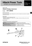
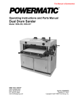
LIST No. E497
Aug. 2007
PRODUCT NAME
Hitachi Rotary Hammer
Model
DH 22PG
MARKETING OBJECTIVE
The new Model DH 22PG features the concrete drilling capability with the maximum drill bit diameter 22 mm and
the use of SDS-plus shank tools. This is a professional-use and low-priced rotary hammer.
The main features of the Model DH 22PG are as follows:
(1) Most compact and lightweight in its class: 289 mm in overall length and 1.9 kg in weight
(2) The internal pressure adjustment mechanism prevents grease leakage.
(3) The idle striking prevention mechanism prevents reciprocating motion during no-load operation to reduce
noise.
APPLICATIONS
Drilling holes in concrete, brick and stone
Drilling holes in steel and wood
Tightening and loosening machine screws and wood screws
SELLING POINTS
[ NEW FEATURES ]
Most compact and lightweight in its class for
ease of operation
Hitachi’s own internal pressure adjustment
mechanism
Clutch-cut type idle striking prevention
mechanism
SPECIFICATIONS AND PARTS ARE SUBJECT TO CHANGE FOR IMPROVEMENT
International Sales Division
REMARK:
For more information about HANDLING INSTRUCTIONS, visit our website at:
http://www.hitachi-koki.com/manual_view_export/
Throughout this TECHNICAL DATA AND SERVICE MANUAL, a symbol(s) is(are) used in the place of
company name(s) and model name(s) of our competitor(s). The symbol(s) utilized here is(are) as follows:
Symbols utilized
Competitors
Company name
Model name
B
BOSCH
GBH2-22RE
C
MAKITA
HR2020
CONTENTS
Page
SELLING POINT DESCRIPTIONS ---------------------------------------------------------------------------------------- 1
SPECIFICATIONS ------------------------------------------------------------------------------------------------------------- 2
1. Specifications----------------------------------------------------------------------------------------------------- 2
2. Optional accessories ------------------------------------------------------------------------------------------- 3
COMPARISONS WITH SIMILAR PRODUCTS------------------------------------------------------------------------- 7
1. Specifications comparisons ---------------------------------------------------------------------------------------------------------- 7
2. Drilling speed comparison------------------------------------------------------------------------------------- 8
PRECAUTIONS IN SALES PROMOTION------------------------------------------------------------------------------- 9
Safety Instructions-------------------------------------------------------------------------------------------------- 9
REFERENCE MATERIALS-------------------------------------------------------------------------------------------------10
1. Lubrication -------------------------------------------------------------------------------------------------------10
2. Tool structure ----------------------------------------------------------------------------------------------------10
3. Changeover between ”Rotation only” and ”Rotation and hammering” ----------------------------13
4. Precautions for use of ”Rotation only” (no hammering) function------------------------------------13
5. Drill bits -----------------------------------------------------------------------------------------------------------13
6. Tool retainer section -------------------------------------------------------------------------------------------14
7. Dust collector (B) -----------------------------------------------------------------------------------------------15
REPAIR GUIDE----------------------------------------------------------------------------------------------------------------16
1. Precautions in disassembly and reassembly ------------------------------------------------------------16
STANDARD REPAIR TIME (UNIT) SCHEDULES--------------------------------------------------------------------26
Assembly diagram for DH 22PG
SELLING POINT DESCRIPTIONS
Most compact and lightweight in its class*
* Based on our own research
The Model DH 22PG is most compact and lightweight in its class thanks to the optimum striking
mechanism.
HITACHI
Maker
Model
DH 22PG
B
C
Overall
length
289 mm
342 mm
352 mm
Weight
1.9 kg
2.3 kg
2.3 kg
289 mm
Internal pressure adjustment mechanism
An air passage is provided as shown below to let out air inside the gear cover and let outside air in the gear
cover. This passage is sandwiched between felt packings to pass only air. Thus variations in the internal
pressure are minimized for stable hammering operation and prevention of grease leakage.
A-A
(Inside the Gear cover)
Air passage
(Outside the
gear cover)
Felt packing (B)
Valve
Felt packing (A)
Inner cover
Idle striking prevention mechanism
When the drill bit is lifted from the concrete surface, the reciprocating bearing that converts rotation into
reciprocating motion stops to prevent idle striking. Thanks to this mechanism, vibration and noise during
no-load operation are reduced.
-1-
SPECIFICATIONS
1. Specifications
mm
22
Inch
7/8
mm
Inch
13/24
1/2” / 1”
Capacity: Concrete
Capacity: Steel/Wood
Input power
Impact energy
No-load rpm (Forward)
No-load rpm (Reverse)
Full-Load bpm
Mode
W
J
min-1
min-1
min-1
–
620
1.4
0-1,500
0-980
0-6,200
2
Variable speed
–
YES
Reverse switch type
–
Push button
Soft grip
Handle
No
Gear cover No
mm
289
Inch
11-3/8”
m/s2
1.42
m/s2
8.75
dB
83.7
dB
89.2
kg
lbs
1.9
4.2
Overall length
No load vibration level
(Tri-axial, measured)
Full load vibration level
(Tri-axial, measured)
No load noise level
(measured)
Full load noise level
(measured)
Weight
-2-
2. Optional accessories
(1) Drilling anchor holes (rotation and hammering)
Drill bit (SDS-plus shank)
+
Effective length
Overall length
Outer dia.
(mm)
Overall
length
(mm)
Effective
length
(mm)
4.0
4.3
4.5
110
50
4.8
5.0
5.0
5.5
6.0
160
100
110
50
6.0
6.4
6.5
7.0
7.5
8.0
160
100
8.5
9.0
9.5
10.0
10.0
260
200
10.5
160
100
10.5
260
200
11.0
160
100
12.0
166
100
12.0
260
200
Code No.
303571
303572
303573
303574
303575
303578
303576
303577
303579
303580
303581
303582
303583
303584
303585
303586
303587
303588
303604
303589
303605
303590
303591
303606
-3-
Outer dia.
(mm)
Overall
length
(mm)
Effective
length
(mm)
12.5
166
100
12.5
260
200
12.7
166
100
12.7
260
200
166
100
14.3
260
200
14.5
166
100
14.5
260
200
166
100
260
200
166
100
17.0
260
200
17.5
166
100
17.5
260
200
18.0
166
100
19.0
260
200
250
200
13.0
14.0
14.3
15.0
16.0
16.0
16.5
17.0
20.0
22.0
Code No.
303592
303607
303593
303608
303594
303595
303596
303609
303597
303610
303598
303599
303611
303600
303601
308485
303602
303612
303603
303613
303614
303615
Slender bit and adapter for slender shaft (SDS-plus shank)
+
(1) Drill bit (slender shaft)
+
(2) Adapter for slender shaft
(SDS-plus shank)
(1) Drill bit (slender shaft)
Outer dia.
(mm)
3.4
3.5
(2) Adapter for slender shaft
Overall length
(mm)
Effective length
(mm)
Code No.
Code No.
90
45
306369
306368
306370
Drill bit (taper shank)
+
(1) Drill bit (taper shank)
+
(2) Taper shaft adapter
(SDS-plus shank)
(3) Cotter
(1) Drill bit (taper shank)
Outer dia. (mm)
1100
12.3
12.7
14.3
14.5
17.5
(2) Taper shank adapter
Code No.
944460
944461
993038
944462
944500
944463
Type
Code No.
Code No.
Morse taper No. 1
303617
944477
13 mm hammer drill chuck
+
+
Rubber cap
Straight-shank bit for
impact drills
(3) Cotter
13 mm hammer drill chuck
(SDS-plus shank)
Chuck wrench
-4-
Part name
13 mm hammer drill chuck (including chuck wrench and rubber cap)
Chuck wrench
Rubber cap
Code No.
303332
303334
303335
(2) Anchor setting
Anchor setting bar
Anchor setting adapter
(SDS-plus shank)
+
Overall
length (mm)
W-1/4 Anchor setting adapter-A
260
W-5/16 Anchor setting adapter-A
260
W-3/8 Anchor setting adapter-A
160
W-3/8 Anchor setting adapter-A
260
Part name
Code No.
302976
302975
303621
302974
Overall
Code No.
length (mm)
W-1/4 Anchor setting adapter-B
260
302979
W-5/16 Anchor setting adapter-B
260
302978
W-3/8 Anchor setting adapter-B
160
303622
W-3/8 Anchor setting adapter-B
260
302977
Part name
Internal cone type
External cone type
(3) Crushing operation (rotation and hammering)
+
Bull point (SDS-plus shank)
Code No. 303046
(4) Drilling holes and driving screws (rotation only)
+
+
Special screw
13 mm drill chuck
(13VLRB-D)
Chuck wrench
Chuck adapter (G)
(SDS-plus shank)
NOTE:
If the tool is to be used for tightening or loosening screws,
open the three jaws of the drill chuck and securely fix the drill
chuck to chuck adapter (G) with the special screw (a left-hand
threaded M6 screw) when mounting the drill chuck onto chuck
adapter (G).
-5-
Part name
Code No.
Chuck adapter (G)
13 mm drill chuck (with chuck wrench)
Special screw (M6 left-hand threaded)
303623
321814
981122
(1) Cross-recessed head (Phillips) bit
[Overall length: 65 mm]
(For use with cross-recessed head (Phillips) screw)
(2) Slotted-head (minus) bit
[Overall length: 70 mm]
(For use with slotted-head (minus) screw)
Tip thickness
Stamped bit No.
Bit No.
Code No.
Applicable screw dia. (mm)
Bit tip thickness
Code No.
No. 2
No. 3
983006
983011
3-5
6- 8*
0.8
1
955659
955674
* Temporary tightening
(5) Grease for hammer and hammer drill
Containing 500 g
Code No. 980927
Containing 30 g
Containing 70 g
Code No. 981840
Code No. 308471
(6) Dust cup and dust collector (B)
Dust cup
Dust collector (B)
Code No. 971787
Code No. 306885
-6-
Applicable screw
dia. (mm)
4
5- 6
COMPARISONS WITH SIMILAR PRODUCTS
(Superior specifications:
1. Specifications comparisons
Maker
Model name
HITACHI
DH22PG
B
C
mm
22
22
20
Inch
7/8”
7/8”
13/16”
mm
13/24
13/30
13/32
Inch
1/2” / 1”
1/2” / 1-3/16”
1/2” / 1-1/4”
Input power
W
620
620
710
Impact energy
J
1.4
2.2
2.2
No-load rpm (Forward)
min-1
0-1,500
0-1,000
0-1,050
No-load rpm (Reverse)
min-1
0-980
0-1,000
0-525
Full-load bpm
min-1
0-6,200
0-4,400
0-4,050
Mode
-
2
2
2
Variable speed
-
Yes
Yes
Yes
Reverse switch type
-
Push button
CB holder
Switch Lever
Handle
No
Yes
No
Gear
cover
No
No
No
mm
289
342
352
Inch
11-3/8”
11-15/32”
13-55/64”
m/s2
1.42
12.4
8.7
m/s2
8.75
16.8
16.2
dB
83.7
91.3
87.7
dB
89.2
87.1
85.0
kg
1.9
2.3
2.3
lbs
4.2
5.1
5.1
-
Yes
No
No
-
Yes
No
No
Capacity: Concrete
Capacity: Steel/Wood
Soft grip
Overall length
No-load vibration level
(Tri-axial, measured)
Full-l load vibration level
(Tri-axial, measured)
No-l load noise level
(measured)
Full-l Load noise level
(measured)
Weight
Internal pressure
adjustment mechanism
No-load hammering
prevention mechanism
-7-
)
2. Drilling speed comparison
Drilling speed varies considerably depending on the work conditions. Use the factory test results shown in
Fig. 1 for comparison purpose only.
Fig. 1
800
HITACHI DH22PG
B
C
700
600
Drilling speed (mm/min)
500
400
300
200
100
0
2
4
6
8
10
12
14
16
18
20
22
Drill bit dia.(mm)
[Test conditions]
Direction: Downward drilling
Pushing force: 98 N (10 kgf)
Test material: Concrete panel with a compression strength of 2,352 N/cm2 (240 kgf/cm2)
-8-
PRECAUTIONS IN SALES PROMOTION
Safety Instructions
In the interest of promoting the safest and most efficient use of the Model DH 22PG Rotary hammer by all
of our customers, it is very important that at the time of sale, the salesperson carefully ensures that the
buyer seriously recognizes the importance of the contents of the Handling Instructions, and fully
understands the meaning of the precautions listed on the Caution Plate and Name Plate attached to each
tool.
A. Handling Instructions
Although every effort is made in each step of design, manufacture and inspection to provide protection
against safety hazards, the dangers inherent in the use of any electric tool cannot be completely eliminated.
Accordingly, general precautions and suggestions for the use of electric power tools, and specific
precautions and suggestions for the use of the Rotary Hammer are listed in the Handling Instructions to
enhance the safe, efficient use of the tool by the customer. Salespersons must be thoroughly familiar with
the contents of the Handling Instructions to be able to offer appropriate guidance to the customer during
sales promotion.
B. Caution Plate
The Model DH22PG unit is provided with a Caution Plate (illustrated below) which lists basic safety
precautions in use. Carefully ensure that the customer fully understands and follows these precautions
before using tool.
[For Australia and New Zealand]
[ For the U.S.A. and Canada ]
[ For China ]
[ For Mexico ]
[ For Taiwan ]
-9-
REFERENCE MATERIALS
1. Lubrication
Replenish the grease lubricant when the tool is disassembled or there is grease leakage due to a defective
seal. Changing grease is required once a year to extend the service life of the tool. Special grease is used
in the striking section. Should the striking section (within the gear cover) be disassembled, remove the old
grease from all parts completely and, on reassembly, replenish 30 g of new grease in the gear cover and 10
g in the groove of the inner cover. Be careful not to exceed the designated amount of grease. Excessive
grease will reduce striking efficiency.
2. Tool structure
Transmission of rotation
See Fig. 2. The rotation of the armature is transmitted to the second shaft via the first gear, and causes
it to rotate. The second shaft pinion mounted on the second shaft engages with the second gear
mounted on the outer circumference of the cylinder. The cylinder is coupled to the second gear by
means of a slip mechanism, and they rotate together. The end of the cylinder also functions as the drill
bit retainer. The cylinder is key-connected to the inserted drill bit by means of two key rails and a steel
ball, and transmits rotation to the drill bit.
Piston reciprocating mechanism
In the Model DH 22PG, through adoption of a spiral drive system (a mechanism using a reciprocating
bearing), a more compact design has been achieved by arranging the motor shaft in parallel with the
tool shaft. Figure 2 shows that the drill bit is pressed against the workpiece and the tool shaft is
retracted. The rotation of the armature is transmitted to the second shaft via the first gear. The second
shaft rotation is further transmitted through a spline to the clutch. The cylinder flange is pressed against
the clutch by the retracted tool shaft and the clutch engages with the reciprocating bearing to transmit
rotation to the reciprocating bearing. However, ring grooves on the inner race of the reciprocating
bearing are positioned on an angle of inclination with relation to the second shaft.
Fig. 2
Rod
Piston pin
Air chamber
Piston
O-ring
Slip mechanism
Strike
Tool shaft
Armature
Motor shaft
Cylinder
Second hammer
Second gear
Second pinion
Clutch
First gear
Ring groove
Ringed
ditch
Second shaft
Cylinder flange
Second shaft spline
Reciprocating bearing
The rotation of the inner race and the shaft causes that angle of inclination to change regularly forward
and backward with relation to the second shaft, and produces a rocking motion to the outer race of the
reciprocating bearing. Finally, a rod extending from the outer race of the reciprocating bearing is
connected to the piston by the piston pin, and causes the reciprocating bearing motion of the piston.
-10-
Hammering function
The piston reciprocates within the cylinder to move the striker in the same manner as in conventional
hammer drills. As the piston reciprocates, the changing air pressure inside the air chamber between the
piston and the striker causes the striker to move and continuously strike against the end of the second
hammer. At the same time, the changing air pressure within the air chamber which moves the striker
also provides an “air cushion” which absorbs the impact of the hammering action. As any air leakage
from the air chamber would weaken the air-cushion effect and reduce impact absorption, the O-ring
(mounted on the striker) is extremely important to seal the air. Although special rubber material is
utilized in construction of the O-ring to make its effective service life as long as possible, wear cannot be
fully avoided. Accordingly, it is recommended that the O-ring be replaced approximately once a year,
depending on the frequency of usage of the tool.
Idle striking prevention mechanism
The idle striking prevention mechanism in the Model DH 22PG is different from those of conventional
hammer drills in other classes. When the drill bit is lifted from the concrete surface on completion of
drilling or during no-load operation, the reciprocating bearing that converts rotation into reciprocating
motion stops to prevent idle striking.
Upon lifting the drill bit from the concrete surface, the tool shaft (cylinder) is moved forward about 5 mm
by the force of spring (B) as shown in Fig. 3. Then the clutch is moved forward by the thrust plate that is
connected to the cylinder to disengage the clutch from the reciprocating bearing. Thanks to the needle
bearing on the second shaft, the reciprocating bearing can idle. Accordingly, rotation of the second
shaft is not transmitted to the reciprocating bearing and the reciprocating bearing stops to stop the
striking motion of the piston and the striker. The pressing force of spring (B) is as low as 1.0 kg to 2.0 kg
in comparison with the conventional mouth system. The Model DH 22PG is also suitable for drilling in
upward direction.
Fig. 3
5 mm
Piston
Spring (B)
Thrust plate
Slip mechanism Striker
Tool shaft
Cylinder
Coil spring
Second gear
Clutch
Reciprocating bearing
Needle bearing
-11-
Cylinder flange
Internal pressure adjustment mechanism
An air passage is provided as shown in Fig. 4 to let out air inside the gear cover and let outside air in the
gear cover. This passage is sandwiched between felt packings to pass only air (pressure). Thus
variations in the internal pressure are minimized for stable hammering operation and prevention of
grease leakage.
Fig. 4
A-A
(Inside the Gear cover)
Air passage
(Outside the
Gear cover)
Felt packing (B)
Valve
Felt packing (A)
Inner cover
Slip mechanism
The slip mechanism in the Model DH 22PG consists of a coil spring which applies a pre-set amount of
pressure to ensure the interlocking of three claws provided on the flange of the cylinder (the final
rotating shaft) and three matching claws provided on the face of the second gear, by which rotation is
transmitted to the cylinder. The second gear is fitted on the cylinder with a certain amount of play. If an
excessively large torque is applied to the tool shaft (cylinder), the force of the torque will exceed the
pressure of the coil spring and cause the claws on the second gear to disengage from and ride over the
claws on the cylinder so that the second gear idles and does not transmit rotation. Even should the drill
bit come in contact with a reinforcing bar within the concrete, causing sudden excessive torque, the slip
mechanism functions to prevent damage to the gears, and possible loss of control of the tool by the
operator (slip torque setting applied to the tool shaft: 1.7 to 2.2 kgm).
Sealed and dustproof construction
The gear cover is totally enclosed by oil seals, O-rings and other devices to prevent leakage of
lubricating grease, and to keep dust and dirt out of the internal mechanisms. The drill bit chuck portion is
protected by a rubber front cap to keep out dust and chips which could cause improper fitting of the drill
bit and/or other faulty operation of the chuck portion. The speed control switch is also fully dustproof to
prevent dust and chips from entering the handle section and causing possible operational trouble or a
breakdown of the insulation.
Speed control
The Model DH 22PG is equipped with a variable speed control switch which permits free change of the
rotation speed and hammering force. When drilling in fragile materials, pull the switch trigger gently for
low rotation speed (hammering force) to achieve optimum results. Note that the switch trigger cannot be
pulled to the full but up to the half in the reverse drilling, and the speed is about half of the forward
drilling. In addition, the switch stopper cannot be used in the reverse drilling.
-12-
3. Changeover between “Rotation only” and “Rotation and hammering”
The change lever on the Model DH 22PG permits easy changeover between the “rotation only” and
“rotation and hammering” functions. Set the change lever to “rotation and hammering” ( marks). Press
the drill bit against the workpiece and pull the switch trigger. Then the armature starts rotating, and the
rotation and the striking force are transmitted to the drill bit by the mechanism as described in page 10
“Piston reciprocating mechanism.” After drilling, take the drill bit away from the workpiece. Then the
rotation of the reciprocating bearing and the hammering operation are stopped by the idle striking
prevention mechanism as described in page 11. Set the change lever to “rotation only” (
mark). The
stopper of the change lever contacts the rear surface of the thrust plate that is pushed forward by spring
(B). Thus the cylinder cannot go back even if the main body is pressed, and the claws on the clutch
cannot engage the matching claws on the reciprocating bearing. The reciprocating bearing idles on the
second shaft and only the rotation is transmitted to the drill bit.
4. Precautions for use of “Rotation only” (no hammering) function
The Model DH 22PG is equipped with a change lever for changeover between “rotation only” and “rotation
and hammering” functions. Be sure to set the change lever to “rotation only” for drilling into wood or metal
materials or for driving screws by means of the optional chuck adapter or drill chuck. Should the change
lever be set to “rotation and hammering” when such an optional tool is used for drilling or driving screws,
the hammering action may cause the drill chuck or other optional tool to be broken or damaged.
Salespersons should carefully ensure that the buyer is thoroughly advised on this point.
5. Drill bits
The chuck section is designed exclusively for the popular and widely available SDS-plus shank bits, as
shown in Fig. 5. Rotating torque is transmitted to the drill bit by two key rails provided in the tool holding
section. A steel ball is used to prevent the bit from falling out.
Fig. 5
The service life of a drill bit with a diameter of 8 mm is approximately 300 holes when drilling into concrete
with a depth of 30 mm. If reground before the end of its service life, the drill bit will continue to provide
efficient drilling. Figure 6 shows the regrinding angle.
-13-
Fig. 6
6. Tool retainer section
The tool retainer is structured as shown in Fig. 7.
The tip of the tool retainer is covered with the front cap (made of rubber) to prevent dust and chips from
getting inside. The steel ball falls into the round groove of the bit to prevent the tool from coming off and the
two key rails transmit the rotation torque. To mount the bit, push the bit in the tool retainer as far as it will go.
Pushing lightly, turn the bit until it is caught. At this position, push the bit in as far as it will go (sliding the grip
is not required for mounting the bit). To remove the bit, slide the grip backward to the full and remove the
bit.
Fig. 7
Grip
Ball holder
Holder spring
Steel ball
Front cap
Stopper ring
Cylinder
Holder plate
-14-
Key rail (2 pcs.)
7. Dust collector (B)
When drilling holes overhead, dust collector (B) (optional accessory) can be mounted on the Model
DH 22PG to prevent dust and chips from falling downward. Dust collector (B) is intended solely for use
when drilling holes in concrete, and cannot be used for drilling holes in steel or wood. It is designed for use
with drill bits with overall length of 166 mm, 160 mm and 110 mm, and cannot be used with any longer bits.
When using a drill bit with an overall length of 166 mm with dust collector (B), drilling up to a depth of
approximately 72 mm is possible. When using dust collector (B), ensure it is securely fastened to the grip
on the main body with socket adapter (B). Although socket adapter (B) rotates together with the tool shank,
there is a steel ball between the outer race and the socket which serves as a ball bearing. Should the dust
cover be forced against the concrete surface, it will not rotate even though the tool shank continues to
rotate. Should the tool be operated when the dust cover is not being held against a concrete surface,
friction may cause dust collector (B) to become disconnected from the grip. Accordingly, caution the
customer to press dust collector (B) and drill bit firmly against the concrete surface before tuning on the
switch to start drilling. When dust collector (B) is used, almost no dust and chips are scattered about.
However, since the chips and dust remaining in the collector may scatter after completion of the drilling
operation, the customer should be advised to always wear protective glasses. When dust collector (B) is
disassembled for repair or maintenance, be very careful to prevent oil or grease from adhering to the steel
balls. Grease or oil on the steel balls may cause concrete dust to enter the unit and cause defective
rotation.
Fig. 8 Dust collector (B) structure
-15-
REPAIR GUIDE
Be sure to disconnect the power cord plug from the wall outlet before repairing. Otherwise, the motor turns
abruptly and it is very dangerous.
1. Precautions in disassembly and reassembly
The [Bold] numbers in the description below correspond to the item numbers in the Parts List and the
exploded assembly diagram for the Model DH 22PG.
Disassembly
1. Disassembly of the tool retainer
Slide the Grip [3] fully in the arrow direction as shown in Fig. 9 and remove the Front Cap [1]. Pulling the
Grip [3] in the arrow direction as shown in Fig. 10, remove the Stopper Ring [2] with a retaining ring puller.
Then the Grip [3], Ball Holder [4], Steel Ball D7.0 [18], Holder Plate [5] and Holder Spring [6] can be
removed from the Cylinder [19].
Fig. 10
Fig. 9
Grip [3]
Grip [3]
Holder Spring [6]
Steel Ball D7.0 [18]
Cylinder [19]
Stopper Ring [2]
Front Cap [1]
Holder Plate [5]
Ball Holder [4]
2. Disassembly of the hammering mechanism
Set the Lever [14] to “rotation and hammering” ( marks). Remove the Tapping Screw (W/Flange) D4 x 30
(Black) [8] from the Gear Cover [7] to remove the Gear Cover [7]. At this time, check that the Spacer [35]
at the tip of the Second Shaft [36] is not adhered to the ball bearing press-fitted into the Gear Cover [7].
Remove the Spacer [35] from the tip of the Second Shaft [36] and move the Piston [30] to the top dead
center (Inner Cover Ass’y [33] side) by turning the Second Shaft [36]. Then the arm of the Reciprocating
Bearing [38] can be removed from the Piston Pin [34] and the components mounted on the Second Shaft
[36] can be removed from the Inner Cover Ass’y [33] as a unit.
Remove the First Gear [40] from the Second Shaft [36] with a bearing puller and remove the Reciprocating
Bearing [38], Needle Cage [39] and Clutch [37] from the Second Shaft [36].
Note that the First Gear [40] is aligned with and press-fitted onto the 9 mm diameter end surface of the
Second Shaft [36].
-16-
3. Removal of the Cylinder [19] and the Second Gear [17] (slip mechanism section)
Remove the Machine Screw M4 x 5 [15] securing the Lever [14] to the Stopper [12] from the inside of the
Gear Cover [7]. Pull out the Lever [14] from the Gear Cover [7]. Then the Stopper [12] can be removed.
Push the tip of the Cylinder [19] to remove the Cylinder [19] from the Gear Cover [7]. Remove the
Retaining Ring for D25 Shaft [10] from the Cylinder [19] with a retaining ring puller. Then the Second Gear
[17], Spring (A) [16] and Washer [11] can be removed from the Cylinder [19].
4. Removal of the Cylinder [19] and the Second Hammer [20]
Remove the Stopper Ring [24] from the inner circumference of the Cylinder [19]. Then the Hammer Holder
[23], Second Hammer [20] and O-ring (P-15) [22] can be removed from the Cylinder [19].
As shown in Fig. 11, insert punch (A) [J-85] into the 4 mm dia. hole (2 pcs.) of the Cylinder [19] and tap the
Stopper Ring [24] until the Stopper Ring [24] cannot be seen from the 4 mm dia. hole (2 pcs.) to remove the
Stopper Ring [24] from the groove of the inner circumference of the Cylinder [19]. Then, pull out the
Stopper Ring [24] from the inner circumference of the Cylinder [19] with a retaining ring puller (B) (J-341)
being careful not to pop out the Stopper Ring [24]. At reassembly, replace the Stopper Ring [24] with new
one as the removed Stopper Ring [24] is deformed.
Fig.11
Tap with a hammer.
Punch (A) (J-85)
O-ring (P-15) [22]
4 mm dia. hole (2 pcs.)
Second Hammer [20]
Cylinder [19]
Hammer Holder [23]
Stopper Ring [24]
-17-
Reassembly
Reassembly can be accomplished by following the disassembly procedure in reverse. However, special
attention should be given to the following items.
1. Application of lubricant
Apply special grease to the lip portion of the oil seal in the Gear Cover [7], inner circumference of the
needle bearing, clutch claws of the Second Gear [17] and the Cylinder [19], inner circumference of the
needle bearing in the Inner Cover Ass’y [33], O-ring (B) [21] of the Second Hammer [20], O-ring (P-15)
[22], O-ring (A) [26] of the Striker [25], inner and outer circumference of the Piston [30], Washer [31], claw
portion of the Clutch [37], claw portion, inner circumference and arm portion of the Reciprocating Bearing
[38] and O-ring (1AP-10) [13] of the Lever [14].
Fill 30 g of special grease in the Gear Cover [7] and 10 g in the groove of the Inner Cover Ass’y [33]. Apply
Hitachi Motor Grease No. 29 to the Steel Ball D7.0 [18].
2. Reassembly of the Cylinder [19] section
Mount the O-ring (P-15) [22], Second Hammer [20], O-ring (B) [21] and Hammer Holder [23] in the
Cylinder [19] as shown in Fig. 12. Push the new Stopper Ring [24] in the Cylinder [19] at an angle and fit it
in the groove with a hand press using the stopper ring jig [J-234]. Check that the Stopper Ring [24] is
securely fitted in the groove of the Cylinder [19] viewing from the 4 mm dia. hole (2 pcs.) on the Cylinder
[19].
Stopper ring groove
Fig. 12
4 mm dia. hole (2 pcs.)
O-ring (P-15) [22]
Second Hammer [20]
Cylinder [19]
Hand press
O-ring (B) [21]
Stopper ring jig (J-234)
Stopper Ring [24]
Hammer Holder [23]
3. Mounting the Lever [14]
Mount the Second Gear [17], Spring (A) [16] and Washer [11] to the Cylinder [19] and secure them with
the Retaining Ring for D25 Shaft [10]. Push this assembly in to the tip of the Gear Cover [7] and mount the
Holder Spring [6], Holder Plate [5] and Steel Ball D7.0 [18] to the tip of the Cylinder [19]. Mount the Ball
Holder [4], Grip [3], Stopper Ring [2] and Front cap [1]. Mount the Thrust Washer [27] to the Cylinder [19].
Show the Lever [14] in the Gear Cover [7] and fit the Stopper [14] in the groove of the Lever [14] then push
the Lever [14] in the Gear Cover [7] hard. Secure the Lever [14] to the Gear Cover [7] with the Machine
Screw M4 x 5 [15]. When assembling the component parts, be sure to set the Lever [14] to “rotation and
marks).
hammering” (
4. Press-fitting the First Gear [40]
Press-fit the First Gear [40] aligning with the shaft end surface of the Second Shaft [36]. After press-fitting
the First Gear [40], check that the inside ring of the Reciprocating Bearing [38] turns smoothly.
-18-
5. Reassembly of the internal pressure adjustment mechanism
As shown in Fig.13, push Felt Packing (A) [43], Valve [44] and Felt Packing (B) [45] in the Inner Cover
Ass’y [33] as far as they will go in this order.
Fig. 13
A-A
Felt Packing (B) [45]
Valve [44]
Felt Packing (A) [43]
Inner Cover Ass’y [33]
6. Mounting the Piston [30]
Mount the Piston [30] as shown in Fig. 14. At this time, mount the Thrust Plate [28] aligning the change
lever pocket of the Inner Cover Ass’y [33] with the notch of the Thrust Plate [28]. (See Fig. 15.)
Fig. 14
Spring (B) [29]
Inner Cover Ass’y [33]
Thrust Plate [28]
Piston [30]
O-ring (A) [26]
Striker [25]
Inner Cover Ass’y [33]
Second Shaft [36]
Spacer [35]
Clutch [37]
Needle Cage [39]
Reciprocating Bearing [38]
Washer (B) D12.5 [41]
First Gear [40]
-19-
Fig.15
Change lever pocket
Notch
Thrust Plate [28]
Inner Cover Ass’y [33]
7. Tightening torque
Tapping Screw D4 [8] [52] [69] [72] ----------------------- 1.47 – 2.45 N•m (15 – 25 kgf•cm)
Machine Screw M4 x 5 [15]---------------------------------- 0.39 – 0.78 N•m (4 – 8 kgf•cm)
8. Wiring diagrams
(1) Product with noise suppressor
Fig. 16
Gray
Black or brown
Choke coil
White
St
Brown
Cord ass’y
Noise
suppressor
St
White or blue
Red
Blue
Black
Speed control SW
Choke coil
Reversing SW
-20-
(2) Product without noise suppressor
Fig. 17
Black or brown
Gray
St
White
Brown
Cord ass’y
St
Blue
White or blue
Black
Red
Speed control SW
Reversing SW
-21-
9. Internal wire arrangement and wiring work
A. Internal wire arrangement
(1) Product with noise suppressor
Fig. 18
Brown (Choke coil)
Black (Stator)
Choke Coil (A) Blue [61]
Gray (Stator)
Choke coil (A) Brown [59]
White (Stator)
White (Stator)
Red (Stator)
Blue (Choke coil)
Noise Suppressor [67]
White or blue
Black or brown
-22-
(2) Product without noise suppressor
Fig. 19
Brown (CB)
Black (Stator)
Gray (Stator)
White (Stator)
White (Stator)
Red (Stator)
Blue (CB)
White or blue
Black or brown
-23-
B. Additional wiring work
General internal wiring can be accomplished by referring to paragraphs 8 and 9. The following are special
instructions for switch connection.
(1) Wiring of reversing switch
Insert the lead wire (black) coming from the stator into the terminal (4) of the reversing switch, and the
lead wire (white) into the terminal (3) as shown in Fig. 20. Insert the lead wire (brown) coming from the
carbon brush or choke coil into the terminal (2) and the lead wire (blue) into the terminal (1). After the
insertion, pull each lead wire slightly to check the lead wires do not come off. To disconnect the lead
wires, insert a small flat-blade screwdriver into the windows near the terminals and pull out the lead
wires.
Fig. 20
Wiring of reversing switch
(2) Wiring of speed control switch
Insert each cord into the terminal (1 ) and terminal (2 ) of the speed control switch as shown in Fig.
21 and tighten the screw (tightening torque: 0.6 ± 0.2 N٠m (6 ± 2 kgf٠cm, 5.2 ± 1.7 in-lbs.)).
Insert the lead wire (gray) coming from the stator into the terminal (M1) and the lead wire (red) into the
terminal (M2). Insert each lead wire (white) coming from the noise suppressor into the terminal (C1) and
(C2). After the insertion, pull each lead wire slightly to check the lead wires do not come off. To
disconnect the lead wires, insert a small flat-blade screwdriver into the windows near the terminals and
pull out the lead wires.
Fig. 21
Wiring of speed control switch
-24-
10. Insulation tests
On completion of disassembly and repair, measure the insulation resistance and conduct the dielectric
strength test.
Insulation resistance: 7 M or more with DC 500 V megohm tester
Dielectric strength: AC 4,000 V/1 minute, with no abnormalities 220 V - 240 V
(and 110 V for U.K. products)
: AC 2,500 V/1minute, with no abnormalities 110 V - 120 V (except U.K. products)
11. No-load current values
After no-load operation for 30 minutes, the no-load current value should be as follows:
Voltage (V)
110
120
220
230
240
Current (A) max.
3.0
2.8
1.6
1.5
1.4
-25-
STANDARD REPAIR TIME (UNIT) SCHEDULES
MODEL
Variable
Fixed
10
20
30
40
50
Work Flow
DH22PG
Handle Cover
Cord Armor
Switch
Cord
Housing
Stator
Armature Ass’y
O-ring (S-24)
Ball Bearing
(609DD)
Ball Bearing
(608VV)
General Assembly
Second Hammer Cylinder
Second Gear
O-ring (B)
O-ring (P-15) Spring (A)
Hammer Holder
Lever
Front Cap
O-ring (1AP-10)
Grip
Stopper
Ball Holder
Holder Spring
Steel Ball D7.0
Gear Cover
Striker
O-ring (A)
Thrust Washer
Thrust Plate
Spring (B)
Piston
O-ring (A)
Piston Pin
Washer (A)
-26-
Inner Cover
Ass’y
Second Shaft
Clutch
Reciprocating
Bearing
Needle Cage
First Gear
Ball Bearing
(626VV)
60 min.
Hitachi Power Tools
LIST NO. E497
ELECTRIC TOOL PARTS LIST
ROTARY HAMMER
Model DH 22PG
1
2007
•
6•4
(E1)
2
3
4
5
6
16
7
17
8
18
19
9
20
10
11
21
22
12
23
24
13
25
14
26
27
28
15
29
30
46
31
47
32
48
49
34
33
50
35
51
36
52
37
53
38
54
39
55
40
41
42
43
62
61
44
63
45
60
64
59
58
71
57
72
501
56
65
502
70
69
68
503
66
67
PARTS
ITEM
NO.
1
DH 22PG
CODE NO.
NO.
USED
DESCRIPTION
306-345
FRONT CAP
1
2
306-340
STOPPER RING
1
3
325-597
GRIP
1
4
327-879
BALL HOLDER
1
5
324-526
HOLDER PLATE
1
6
322-812
HOLDER SPRING
1
7
327-873
GEAR COVER
1
8
305-490
TAPPING SCREW (W/FLANGE) D4X30 (BLACK)
4
NAME PLATE
1
RETAINING RING FOR D25 SHAFT
1
9
10
965-469
11
944-274
WASHER
1
12
327-875
STOPPER
1
13
872-654
O-RING (1AP-10)
1
14
325-594
LEVER
1
15
949-213
MACHINE SCREW M4X5 (10 PCS.)
1
16
306-334
SPRING (A)
1
17
306-333
SECOND GEAR
1
18
959-156
STEEL BALL D7.0 (10 PCS.)
1
19
327-876
CYLINDER
1
20
327-877
SECOND HAMMER
1
21
301-672
O-RING (B)
1
22
311-814
O-RING (P-15)
1
23
327-878
HAMMER HOLDER
1
24
306-340
STOPPER RING
1
25
325-601
STRIKER
1
26
306-326
O-RING (A)
1
27
327-880
THRUST WASHER
1
28
325-588
THRUST PLATE
1
29
306-976
SPRING (B)
1
30
306-324
PISTON
1
31
328-660
WASHER
2
32
327-870
O-RING (A)
1
33
327-869
INNER COVER ASS’Y
1
34
306-322
PISTON PIN
1
35
325-587
SPACER
1
36
327-871
SECOND SHAFT
1
37
325-584
CLUTCH
1
38
325-585
RECIPROCATING BEARING
1
39
306-320
NEEDLE CAGE
1
40
327-872
FIRST GEAR
1
41
995-634
WASHER (B) D12.5
1
42
626-VVM
BALL BEARING 626VVC2PS2L
1
43
324-543
FELT PACKING (A)
1
44
324-545
VALVE
1
45
324-544
FELT PACKING (B)
1
46
878-609
O-RING (S-24)
1
47
306-312
FRINGER
1
48
609-DDC
BALL BEARING 609DDC3PS2-L
1
WASHER (A)
1
49
958-915
*
50
360-798U ARMATURE ASS’Y 110V-120V
1
*
50
360-798E
1
--- 2 ---
ARMATURE 220V-230V
REMARKS
INCLUD. 43-45
INCLUD. 47-49, 54, 55
* ALTERNATIVE PARTS
6 -- 07
PARTS
ITEM
NO.
*
50
DH 22PG
CODE NO.
NO.
USED
DESCRIPTION
REMARKS
360-798F
ARMATURE 240V
1
51
327-868
FAN GUIDE
1
52
981-824
HEX. HD. TAPPING SCREW D4X45
2
*
53
340-701C
STATOR 110V-120V
1
*
53
340-701E
STATOR 220V-230V
1
*
53
340-701F
STATOR 240V
1
54
982-631
WASHER (A)
1
55
608-VVM
BALL BEARING 608VVC2PS2L
1
HITACHI LABEL
1
57
327-881
HOUSING
1
58
324-537
INTERNAL WIRE (A) (BROWN)
1 FOR VEN, THA, INA, SYR, SIN, HKG,
56
*
KUW, USA, CAN, IND
*
59
324-549
CHOKE COIL (A) BROWN
1 EXCEPT FOR VEN, THA, INA, SYR, SIN,
HKG, KUW, USA, CAN, IND
60
322-853
PUSHING BUTTON
1
*
61
324-551
CHOKE COIL (A) BLUE
1 EXCEPT FOR VEN, THA, INA, SYR, SIN,
*
62
324-538
INTERNAL WIRE (A) (BLUE)
1 FOR VEN, THA, INA, SYR, SIN, HKG,
HKG, KUW, USA, CAN, IND
KUW, USA, CAN, IND
63
955-203
BRUSH HOLDER
2
64
999-041
CARBON BRUSH (1 PAIR)
2
65
324-536
SWITCH (1P PILLAR TYPE)
1
*
66
953-327
CORD ARMOR D8.8
1
*
66
938-051
CORD ARMOR D10.1
1
*
67
930-039
NOISE SUPPRESSOR
1 EXCEPT FOR VEN, THA, INA, SYR, SIN,
68
937-631
CORD CLIP
1
69
984-750
TAPPING SCREW (W/FLANGE) D4X16
2
*
70
500-390Z
CORD
1 (CORD ARMOR D8.8)
*
70
500-447Z
CORD
1 (CORD ARMOR D8.8) FOR SYR
*
70
500-424Z
CORD
1 (CORD ARMOR D8.8) FOR SIN, KUW
*
70
500-235Z
CORD
1 (CORD ARMOR D8.8) FOR INA, IND
*
70
500-239Z
CORD
1 (CORD ARMOR D10.1) FOR THA
*
70
930-055
CORD
1 (CORD ARMOR D10.1) FOR VEN
*
70
500-408Z
CORD
1 (CORD ARMOR D8.8) FOR NZL, AUS
*
70
500-249Z
CORD
1 (CORD ARMOR D8.8) FOR USA, CAN
*
70
500-446Z
CORD
1 (CORD ARMOR D8.8) FOR GBR (230V)
*
70
500-465Z
CORD
1 (CORD ARMOR D8.8) FOR GBR (110V)
*
70
500-391Z
CORD
1 (CORD ARMOR D8.8) FOR SUI
*
70
500-440Z
CORD
1 (CORD ARMOR D8.8) FOR HKG
*
70
500-456Z
CORD
1 (CORD ARMOR D8.8) FOR CHN
*
70
323-974
CORD
1 (CORD ARMOR D10.1) FOR TPE
*
70
500-475Z
CORD
1 (CORD ARMOR D8.8) FOR KOR
71
327-882
HANDLE COVER
1
72
301-653
TAPPING SCREW (W/FLANGE) D4X20 (BLACK)
3
HKG, KUW, USA, CAN, IND
6 -- 07
* ALTERNATIVE PARTS
--- 3 ---
STANDARD ACCESSORIES
ITEM
NO.
501
CODE NO.
DH 22PG
NO.
USED
DESCRIPTION
327-883
CASE
1
502
324-548
SIDE HANDLE
1
*
503
303-709
DEPTH GAUGE
1
*
503
310-331
DEPTH GAUGE
1
REMARKS
FOR USA, CAN
OPTIONAL ACCESSORIES
ITEM
NO.
CODE NO.
601
308-471
GREASE FOR HAMMER.HAMMER DRILL (70G)
1
602
980-927
GREASE FOR HAMMER.HAMMER DRILL (500G)
1
603
981-840
GREASE (A) FOR HAMMER.HAMMER DRILL (30G)
1
604
321-814
DRILL CHUCK 13VLRB-D
1
605
995-344
FLAT HD. SCREW (A) (LEFT HAND) M6X25
1
606
971-511Z + DRIVER BIT (A) NO. 2 25L
1
607
971-512Z + DRIVER BIT (A) NO. 3 25L
1
608
981-122
SPECIAL SCREW M6X22
1
609
971-794
ANCHOR SETTING ADAPTER A W1/4” (MANUAL)
1
610
971-795
ANCHOR SETTING ADAPTER A W5/16” (MANUAL)
1
NO.
USED
DESCRIPTION
611
971-796
ANCHOR SETTING ADAPTER A W3/8” (MANUAL)
1
612
971-797
ANCHOR SETTING ADAPTER A W1/2” (MANUAL)
1
613
971-798
ANCHOR SETTING ADAPTER A W5/8” (MANUAL)
1
614
971-799
ANCHOR SETTING ADAPTER B W1/4” (MANUAL)
1
615
971-800
ANCHOR SETTING ADAPTER B W5/16” (MANUAL)
1
616
971-801
ANCHOR SETTING ADAPTER B W3/8” (MANUAL)
1
617
971-802
ANCHOR SETTING ADAPTER B W1/2” (MANUAL)
1
618
971-803
ANCHOR SETTING ADAPTER B W5/8” (MANUAL)
1
619
944-477
COTTER
1
620
303-046
BULL POINT (SDS+) 250MM (ROUND SHANK TYPE)
1
621
302-976
ANCHOR SETTING ADAPTER A (SDS+) W1/4X260L
1
622
302-975
ANCHOR SETTING ADAPTER A (SDS+) W5/16X260L
1
623
303-621
ANCHOR SETTING ADAPTER A (SDS+) W3/8X160L
1
624
302-974
ANCHOR SETTING ADAPTER A (SDS+) W3/8X260L
1
625
302-979
ANCHOR SETTING ADAPTER B (SDS+) W1/4X260L
1
626
302-978
ANCHOR SETTING ADAPTER B (SDS+) W5/16X260L
1
627
303-622
ANCHOR SETTING ADAPTER B (SDS+) W3/8X160L
1
628
302-977
ANCHOR SETTING ADAPTER B (SDS+) W3/8X260L
1
629
303-334
CHUCK HANDLE
1
630
930-515
CHUCK WRENCH 10G
1
631
303-332
HAMMER DRILL CHUCK SET 13MM
1
632
303-334
CHUCK HANDLE
1
633
303-335
RUBBER CAP
1
634
321-813
DRILL CHUCK 13VLD-D
1
635
320-859
SYRINGE (BLOW-OUT BULB TYPE)
1
636
303-617
TAPER SHANK ADAPTER (SDS PLUS) NO. 1
1
637
303-618
TAPER SHANK ADAPTER (SDS PLUS) NO. 2
1
638
303-619
A-TAPER SHANK ADAPTER (SDS PLUS)
1
639
303-620
B-TAPER SHANK ADAPTER (SDS PLUS)
1
640
303-624
CHUCK ADAPTER (D) (SDS PLUS)
1
641
303-623
CHUCK ADAPTER (G) (SDS PLUS)
1
--- 4 ---
REMARKS
INCLUD. 605
INCLUD. 632, 633
* ALTERNATIVE PARTS
6 -- 07
OPTIONAL ACCESSORIES
ITEM
NO.
642
CODE NO.
DH 22PG
NO.
USED
DESCRIPTION
321-825
DRILL CHUCK AND ADAPTER SET
1
643
306-369
DRILL BIT (SLENDER SHAFT) D3.4X90
1
644
306-368
DRILL BIT (SLENDER SHAFT) D3.5X90
1
645
306-370
ADAPTER FOR SLENDER SHAFT (SDS PLUS)
1
646
944-460
TAPER SHANK DRILL BIT D11X100
1
647
944-461
TAPER SHANK DRILL BIT D12.3X110
1
648
993-038
TAPER SHANK DRILL BIT D12.7X110
1
649
944-462
TAPER SHANK DRILL BIT D14.3X110
1
650
944-500
TAPER SHANK DRILL BIT D14.5X110
1
651
944-463
TAPER SHANK DRILL BIT D17.5X120
1
652
944-464
TAPER SHANK DRILL BIT D21.5X140
1
653
971-787
DUST CUP
1
654
931-844
STOPPER
1
655
306-885
DUST COLLECTOR (B) ASS’Y
1
656
306-910
SOCKET ADAPTER (B)
1
657
986-802
DUST COLLECTOR ASS’Y
1
658
986-803
DUST COVER
1
659
986-804
SEAL COVER
1
660
948-310
RETAINING RING FOR D30 SHAFT
1
661
958-063
WASHER
1
662
959-150
STEEL BALL D6.35 (10 PCS.)
663
986-805
OUTER RACE
1
664
986-806
SOCKET
1
6 -- 07
REMARKS
INCLUD. 604, 642
INCLUD. 656, 657
INCLUD. 658-664
19
* ALTERNATIVE PARTS
--- 5 ---
DH 22PG
ITEM
NO.
--- 6 ---
CODE NO.
DESCRIPTION
NO.
USED
REMARKS
Printed in Japan 6 -- 07
(070604N)