1
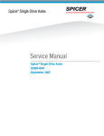
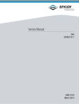
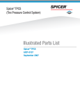
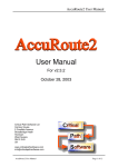
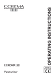
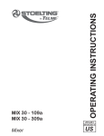
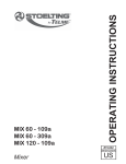
Spicer Axles & Brakes ABIB-0302 Information Bulletin Bulletin Type: Parts / Service Information Topic: Dana LMS™ Hub Assembly Procedure – Steer and Drive Axles Note: Bulletin ABIB-0302 replaces the original bulletin ABIB-9606. The Dana LMS™ hub design eliminates bearing adjustment and variables that cause excessive endplay leading to premature wheel seal failures. The Dana LMS™ hub design combines proven seal technology with precision-manufactured bearing spacers and special tolerance bearings. The Dana LMS™ Hub is available on the following Steer and Drive Axle Models: Steer Axles: E-1000I E-1202I E-1462I E-1200I E-1460I E-1320I Drive Axles: All “R” series spindles only. WARRANTY COVERAGE Installation of the LMS™ Hub requires certification by Dana. The Dana LMS™ Hub is covered for 3 years/350,000 miles for On/ Off-Highway applications, when installation is performed by certified installers, and Dana approved synthetic lubes are used. CAUTION: The wheel seal cannot be reused. Any time the hub is removed from the spindle, the seal must be replaced. Failure to follow this requirement will void warranty. WARNING: Do not attempt to make LMS™ hubs by using LMS™ bearing, spacer and seals in a standard hub. This may result in a seal or bearing failure, which may result in loss of wheel end and or loss of vehicle control. 04/03 1 of 11 ABIB-0302 PARTS INFORMATION IMPORTANT: This is a pre-adjusted wheel hub and bearing system. Components required are a special tight tolerance hub, bearing spacer, bearings, oil bath seal, three or four-piece dowel-type nut system and identification tag. Note: Purchase Genuine replacement Hub and Cup Assemblies through O.E.M. Note: A special installation tool to hold outer bearing cone in place during assembly to spindle is recommended. This also helps prevent cocking of the wheel seal that may occur during installation. WARNING: LMS™ hub components are made to special tight tolerances. Installation and/or servicing with other components will either create excessive endplay or cause excessive pre-load, reducing bearing and seal performance. Wheel separation may also occur. STEER AXLE PARTS LIST Part Name 1 2 DRIVE AXLE PARTS LIST Part Number Part Name * 129381 129384 129372 1 2 3 LMS™ Hub & Cup Assembly Half Stand Bearing Cone Assemblies Bearing Spacer 847 4 Oil Bath Wheel Seal 5 LMS™ Identification Tag Part Number 3 LMS™ Hub & Cup Assembly Half Stand Bearing Cone Assemblies Bearing Spacer * 129375 129378 129373 4 Oil Bath Wheel Seal 5 LMS™ Identification Tag 970576 6 Inner Spindle Nut 815622 7 Dowel Type Lock Washer 815623 8 Tang-Type Lock Washer 817134 6 Inner Spindle Nut 119882 9 10 11 12 Outer Spindle Nut Gasket Hubcap Hubcap bolt 815638 * * * 7 8 9 Dowel Type Lock Washer Tang-Type Lock Washer Outer Spindle Nut 119883 129132 119881 861 129391 (Note: With LMS Hubcap there will not be an identification tag.) *Contact vehicle OEM for specific part numbers. WARNING: Do not attempt to make LMS™ hubs by using LMS™ bearing, spacer and seals in a standard hub. This may result in a seal or bearing failure, which may result in loss of wheel end and or loss of vehicle control. 04/03 2 of 11 ABIB-0302 INSTALLATION PROCEDURE The following service procedures apply to the wheel end assemblies of the Dana steer and drive axle models listed. Follow these service and assembly procedures carefully to obtain proper wheel bearing adjustment and to increase service life. WARNING: Never work under a vehicle supported by only a jack. Always support vehicle with jack stands. Block the wheels and make sure the vehicle will not roll before releasing the brakes. IMPORTANT: Wheel seals can be easily damaged during handling. Leave the seal in its package until installation to prevent damage or contamination. LMS™ HUB ASSEMBLY BUILD UP PROCEDURES: 1. Inspect/Clean the hub cavity, spacer, and bearing bores for any contaminants. Important: Lubricate the wheel seal, and inner and outer bearing cones with the same lubricant used in the axle sump for drive wheel ends or lubricant to be used in hub for steer axles. CAUTION: When using an oil bath system, do not pack the bearings with grease. Grease will prevent the proper circulation of axle lubricant and may cause wheel seal failure. CAUTION: For steer axle hubs, install the bearing spacer into the hub assembly with large diameter end facing the inner bearing cup. This must be done before bearing and seal are installed. 2. With hub or wheel end assembly placed in a flat position, lubricate the inner bearing and install cone into the inner cup of the hub. (see Figure 1) 3. Place the seal on installation tool facing the proper direction. (see Figure 2) Note: Do not apply any bore sealant to seal O.D. or I.D. WARNING: Do not attempt to make LMS™ hubs by using LMS™ bearing, spacer and seals in a standard hub. This may result in a seal or bearing failure, which may result in loss of wheel end and or loss of vehicle control. 04/03 3 of 11 ABIB-0302 CAUTION: The use of improper seal installation tools can distort or damage the seal, cause premature seal failure and void the warranty. 4. Position seal in hub bore. Tap adapter plate around outer edge to position seal. (see Figure 3) 5. Hit tool handle gently. Because of rubber O.D., some seals install much easier than metal O.D. type seals. Once the seal bottoms out in the hub, the seal is installed correctly. Check to be sure the seal is not “cocked” and that unitized seal I.D. and inner bearing turn freely. (see Figure 4) 6. Lubricate I.D. of seal with a light film of clean wheel end lubricant. 7. For drive axle, install the bearing spacer into the hub assembly, large diameter end against the inner bearing cone. 8. Lubricate the outer bearing cone and install into the outer cup of the hub assembly. 9. Install an approved installation tool to the hub cap mounting surface of the hub assembly with two existing nuts/studs or bolts. Hand tighten the nuts/bolts until the installation tool presses against the outer bearing cone. (see Figure 5) 10. The LMS™ Hub assembly is complete and ready for installation on the spindle. CAUTION: Failure to use all required LMS components will increase wheel endplay and reduce seal performance. WARNING: Do not attempt to make LMS™ hubs by using LMS™ bearing, spacer and seals in a standard hub. This may result in a seal or bearing failure, which may result in loss of wheel end and or loss of vehicle control. 04/03 4 of 11 ABIB-0302 LMS™ HUB ASSEMBLY INSTALLATION ONTO SPINDLE PROCEDURE 1. Inspect the spindle and nut threads for corrosion and debris, clean thoroughly or replace as required. 2. Mount the hub assembly onto the axle spindle with a smooth, firm motion. Use care to maintain alignment between the bearing cones and spindle and to avoid seal damage. CAUTION: Never support the hub on the spindle with just the inner bearing and seal. This can damage the seal and cause premature failure. Note: When installing a complete wheel end assembly, a wheel dolly is required during installation to make sure that the wheel seal is not damaged by the weight of the hub, drum and tire. 3. Remove the installation tool from the hub assembly. WARNING: Do not mix spindle nuts and lock washers from different systems. Mixing spindle nuts and lock washers can cause wheel separation. 4. Install the inner spindle nut with dowel pin outward and tighten. (see Figure 6) 5. While rotating wheel end, torque the inner nut: • Steer Hubs 250-300 lb. ft. Do not back off. • Drive Hubs 300-350 lb. ft. Do not back off. 6. While rotating wheel end, torque the inner nut: 7. Install the dowel type washer onto the axle spindle-aligning tab with keyway. If washer does not align with dowel pin on inner nut, remove washer and turn over and reinstall. If after this, washer still does not align with dowel pin, tighten inner nut just enough for alignment. Never tighten the nut more than half the distance between the holes. CAUTION: NEVER back off the spindle nut to align dowel pin with dowel washer. CAUTION: When using LMS™ Hub, always install the identification tag. 8. Install the identification tag onto the spindle over the outside diameter of the dowel-type lock washer, with the anti-rotation bosses inboard and over the flats of the inner spindle nut. Note: The identification tag is retained between the tang-type lock washer and the inner nut. 9. Install the outer wheel nut on the spindle and tighten. 10. Torque the outer spindle nut to 200±50lb. ft. (See Figure 6) Note: If the washer tang and nut flat are not aligned, remove washer, turn it over and reinstall. If required, tighten the outer nut just enough for alignment. CAUTION: NEVER back off the spindle nut to align tang-type washer with spindle nut flats. WARNING: Do not attempt to make LMS™ hubs by using LMS™ bearing, spacer and seals in a standard hub. This may result in a seal or bearing failure, which may result in loss of wheel end and or loss of vehicle control. 04/03 5 of 11 ABIB-0302 11. Secure the outer nut by bending two opposing (180 degrees apart) tangs of the tang-type washer over two flats of the outer nut on drive axle. Bend tang over on steer axles. (See Figure 6) WARNING: Attempts to measure wheel endplay of the completed LMS™ hub system may result in false readings. If endplay measurements are attempted, use a precision dial indicator. Apply a strong push on the hub while rotating the hub back and forth. Work the hub until the dial indicator shows no additional movement. Then apply a strong pull while rotating the hub back and forth. Work the hub until the dial indicator shows no additional movement. Endplay measurements greater than .008” may indicate a need to verify the correct components were used and the spindle nut was installed per the specifications. WARNING: LMS™ hub components are made to special tight tolerances. Installation and/or servicing with other components will either create excessive endplay or cause excessive pre-load, reducing bearing and seal performance. Wheel separation may also occur. 12. Install new gasket on axle shaft flange for drive axles or install new gasket on hub cap for steer axles. 13. Install axle shaft on drive axle or install hub cap on steer axle. Tighten axle flange nuts or hub cap nuts to specified torque. 14. Fill and lubricate axle and wheel ends with Dana approved synthetic lubes. (See Wheel End Lubrication Procedure.) Note: Purchase Genuine replacement Hub and Cup Assemblies through O.E.M. WARNING: Do not attempt to make LMS™ hubs by using LMS™ bearing, spacer and seals in a standard hub. This may result in a seal or bearing failure, which may result in loss of wheel end and or loss of vehicle control. 04/03 6 of 11 ABIB-0302 WHEEL END LUBRICATION CAUTION: Before operating the axle, the wheel hub cavities and bearings must be lubricated to prevent failure. When wheel ends are serviced, follow Dana’s wheel end lubrication procedure before operating the axle. Steer Axles Lubrication fill – Oil type wheel ends Note: Wheel hub configurations vary, allowing different amounts of oil to be added depending on design. Allow for the oil to seep through the outer bearing and fill the hub cavity. Note: During this fill operation, do not allow the oil to go above the centerline or weep hole. This may result in a weeping condition that may be perceived as a leaking hubcap. Continue to add oil until the oil reaches the oil level line as indicated on the hubcap. Center Fill Port: 1. Hub mating surface must be free of dirt, burrs, and radial score lines. 2. Hub mating surface, hubcap flange, and gasket should not be greased or oiled. 3. Always install and reinstall a hubcap with a new gasket. 4. Install the hubcap and tighten hubcap bolts to the specified torque. 5. Fill the hubcap through the center fill port to the proper level (between add and full). 6. Rotate the hub several times then verify the lube is at the proper level. Use only Dana approved synthetic lube. Side Fill Port: 1. Fill wheel end assembly through side fill port with the specified grade of oil. 2. Install side fill hubcap plug and torque to 15- 25 lbs. in. 3. Clean up any overspills that would give the appearance of a leaky hubcap. Lubrication fill – Semi-fluid wheel ends 1. Fill the hub cavity until the lube exits at the 3 and 9 o’clock positions of the outer bearing. This represents a 50% hub cavity fill. 2. Coat the spindle nut and spindle with lube. 3. Place 2 oz of lube on the inner surface of the hubcap. 4. Hub mating surface must be free of dirt, burrs, and radial score lines. 5. Hub mating surface, hubcap flange, and gasket should not be greased or oiled. 6. Always install and reinstall a hubcap with a new gasket. 7. Install the hubcap and tighten hubcap bolts to the specified torque. WARNING: Do not attempt to make LMS™ hubs by using LMS™ bearing, spacer and seals in a standard hub. This may result in a seal or bearing failure, which may result in loss of wheel end and or loss of vehicle control. 04/03 7 of 11 ABIB-0302 Drive Axles Dana axles may be equipped with either of two wheel end designs: • Wheel ends with an oil fill hole. (see figure below) • Wheel ends without an oil fill hole. (see figure below) Wheel Ends with an oil fill hole proceed as follows: 1. Rotate the wheel end hub until the oil fill hole is up. 2. Remove the oil fill plug. 3. Pour 21 oz. of axle sump lubricant into hub cavity through wheel end fill hole. 4. Install oil fill plug and tighten to specified torque. WARNING: Do not attempt to make LMS™ hubs by using LMS™ bearing, spacer and seals in a standard hub. This may result in a seal or bearing failure, which may result in loss of wheel end and or loss of vehicle control. 04/03 8 of 11 ABIB-0302 Wheel Ends without an oil fill hole proceed as follows: (see Figure 9) 5. With axle level and wheel ends assembled, add lubricant through filler hole in axle housing cover until fluid is level with the bottom of filler hole.(figure 1) 6. Raise the left side of the axle 6 inches or more. Hold axle in this position for one minute.(figure 3) 7. Lower the left side. 8. Raise the right side of the axle 6 inches or more. Hold axle in this position for one minute.(figure 4) 9. Lower the right side. 10. With axle on a level surface, add lubricant through housing cover oil filler hole until fluid is level with the bottom of the hole.(figure 1) Note: Axles without wheel end fill holes will require approximately 2.5 additional pints of lubricant to bring the lube level even with the bottom of fill hole. Note: For more detailed information, refer to Dana Wheel End Service Manual WESM-0060. WARNING: Do not attempt to make LMS™ hubs by using LMS™ bearing, spacer and seals in a standard hub. This may result in a seal or bearing failure, which may result in loss of wheel end and or loss of vehicle control. 04/03 9 of 11 ABIB-0302 LMS™ Hub Periodic Inspection and Preventive Maintenance Along with normal pre-trip inspections and current shop preventative maintenance, Dana recommends a complete inspection of the LMS hub during brake and or tire service. Visual Inspection Visually inspect for leakage and oil contamination. 1. Check to see that no oil is present around the hubcap or on the wheel. 2. Check to see that no oil is present on the hub, brake hardware, or brake shoes. CAUTION: If oil is present investigate the cause and take corrective action. 3. Visually inspect the lubricant for discoloration. Under normal conditions, the oil will darken slightly. A white or milky appearance indicates water contamination. If the inspection indicates contamination, completely service the LMS Wheel End. Use genuine LMS replacement parts. IMPORTANT: Replace seals and lubricant every 500,000 miles. SERVICING THE LMS™ HUB ASSEMBLY The LMS™ Hub system is designed for extended service without any maintenance. Since the LMS™ Hub system uses standard size spindle ends, the entire system is serviceable with the ability to re-build with industry available components, should an emergency truck down situation occur. However, to ensure optimum performance of the LMS™ Hub system, Dana suggests that the hub be rebuilt or serviced with the original components. External Inspection 100,000 miles or Annual Inspection Check the lube level and condition of the oil fill hubcap. If lube is contaminated replace lube with the same lubricant. If the lube condition is good and the level is low, fill to the proper level. Check for any signs of leakage at the seal or hubcap gasket areas. Check for soaked brake linings. Take appropriate action if leaks or oil-soaked brake linings are detected. Raise the vehicle and check for smooth rolling of the wheels. Check for tire cupping (not regular tire wear). Check for signs of excessive endplay in the wheels-end. This does not include removal of the hubcap. Note: The semi-fluid grease will not show the normal spreading over the hub and brake components as hubs filled with oil. When inspecting for grease leaks, the inspection must be done carefully with the aid of a bright light from a flashlight or droplight. A slight weep or wetness of grease on the exterior of the seal is typical and does not necessarily require seal replacement. Note: If a gasket leak is noted, replace the gasket. If a seal leak is detected, remove and replace the wheel seal and rebuild with original LMS™ components. 1. Replace the wheel seal, hubcap gasket, and lubricant every time the hub is serviced or at 5 years/500,000 mile intervals. WARNING: Do not attempt to make LMS™ hubs by using LMS™ bearing, spacer and seals in a standard hub. This may result in a seal or bearing failure, which may result in loss of wheel end and or loss of vehicle control. 04/03 10 of 11 ABIB-0302 2. Clean and inspect wheel bearings, cups, spacer and hub any time the hub is serviced or at 5 years/500,000 mile intervals and replace if damaged. In case of emergency field repair, and LMS™ components are not available, the LMS™ hub assembly can easily be converted to a conventional wheel end assembly. This can be done by obtaining the correct standard wheel bearings and removing the spacer. When reassembling industry standard wheel ends, assemble per TMC RP-618. WARNING: Do not attempt to make LMS™ hubs by using LMS™ bearing, spacer and seals in a standard hub. This may result in a seal or bearing failure, which may result in loss of wheel end and or loss of vehicle control. Operating Temperature Check LMS Hub Wheel End as the vehicle enters the service area following a normal run. If the hub is running at a temperature in excess of 150°F above ambient in normal operating conditions, service may be required. Functional Checks Note: Conduct the following inspections with the wheel (s) and drum removed. WARNING: Never work under a vehicle supported by a jack without supporting the vehicle with jack stands and blocking the wheels. 1. Rotate the hub and check for free, smooth, and quiet rotation. If rotation is hampered, the LMS Wheel End should be serviced immediately. 2. Remove the hubcap, and install a dial indicator with a magnetic base on the spindle end. 3. Check the endplay measurement by grasping two wheel studs across from each other on the hub. Pull and push the hub. 4. Record the endplay measurement. CAUTION: LMS Wheel Ends should be serviced if endplay exceeds .006”. 04/03 Printed in USA 11 of 11 ABIB-0302 Copyright Dana Corporation, 2003 All Rights Reserved Dana Corporation Commercial Vehicle Axle Division PO Box 321 Toledo, Ohio 43697-0321 For spec’ing or service assistance, call 1-800-621-8084 24 hours a day, 7 days a week, Or visit our web site at: http://www.spicerparts.com