1
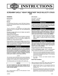
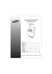
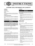
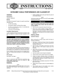
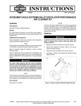
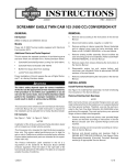
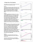
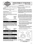
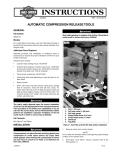
-J05623
REV. 2012-06-29
SCREAMIN' EAGLE VARIABLE PRESSURE CLUTCH
3.
Kit Number
Use the template included in the kit to check the clearance
of the clutch cover. If clearance is not adequate, purchase
spacer kit (Kit Part No. 37000123) separately.
37000121
a.
Cut out the template included in this kit.
Models
b.
See Figure 1. Align bolt-mark on template to the top
bolt hole in the clutch (derby) cover and, then position
the lower side of template between the bottom two
holes in the cover.
c.
Verify that the variable pressure clutch has adequate
running clearance. If it does not, separate purchase
and installation of spacer kit (Kit Part No. 37000123)
is required.
GENERAL
This kit is designed to fit 1999 and later Evolution 1340 and
Twin Cam-equipped models with Original Equipment (OE)
clutch (derby) cover (Except 2003 anniversary models).
Additional Parts Required
Proper installation of this kit requires the separate purchase
of a new clutch cover seal. See the appropriate parts catalog
for the part number.
If an accessory clutch cover is installed, it may not provide
adequate clearance over the new clutch plate. A 1/4 in (6.2
mm) spacer kit (Part No. 37000123) is available for separate
purchase.
The rider's safety depends upon the correct installation
of this kit. Use the appropriate service manual procedures.
If the procedure is not within your capabilities or you do
not have the correct tools, have a Harley-Davidson dealer
perform the installation. Improper installation of this kit
could result in death or serious injury. (00333a)
4.
See the service manual and Figure 2. Add freeplay to the
clutch cable until the adjuster is fully collapsed.
a.
Slide rubber boot (1) off cable adjuster.
b.
Hold cable adjuster (2) and loosen jamnut (3).
c.
Turn cable adjuster until the clutch adjuster is fully
collapsed.
is07353
NOTE
This instruction sheet references service manual information.
A service manual for your model motorcycle is required for this
installation and is available from a Harley-Davidson dealer.
1
Kit Contents
See Figure 7 and Table 1.
2
INSTALLATION
1. Template
2. Clutch cover
Block or jack vehicle under frame in a way that the vehicle
will not fall over. Failure to properly block and/or raise the
vehicle could result in death or serious injury. (00462c)
1.
Position the motorcycle upright on a stand or jack.
2.
See the service manual. Remove the clutch cover.
-J05623
Figure 1. Check Clutch Cover Clearance
Many Harley-Davidson® Parts & Accessories are made of plastics and metals which can be recycled.
Please dispose of materials responsibly.
1 of 3
is07348
3
1
8.
See Figure 4. Starting with the widest tab on the baseplate,
insert it inside the diaphragm spring. Check to make sure
that it is fully seated.
9.
See Figure 5. Starting with one of the bottom levers, install
the variable pressure clutch.
is07351
2
4
1.
2.
3.
4.
Rubber boot
Cable adjuster
Jamnut
Cable end
Figure 2. Clutch Cable Adjuster
NOTE
For 2004 and later Japanese models with helical gear transmissions, back out the adjusting screw at least 3/4 of a turn.
5.
6.
Figure 4. Install Base Plate
Adjust the clutch adjuster screw (2) with the stock retainer
spring in place.
a.
Turn the screw in until it gently bottoms out.
b.
Turn the screw out 1/2 to 1 turn.
is07352
Loosen 6 screws (3) a little at a time and carefully remove
the diaphragm spring retainer (4).
is07349
4
3
Figure 5. Install Variable Pressure Clutch
10. See Figure 5 and Figure 7. Secure the variable clutch.
2
1
1.
2.
3.
4.
Jamnut
Clutch adjuster screw
Screw (6)
Diaphragm spring retainer
Figure 3. Clutch Adjuster Screw and Diaphragm Spring
Retainer
7.
See Figure 7. Bend the tabs of the base plate (2) slightly
to match the angle of diaphragm spring.
-J05623
a.
Start installing each of the bolts (3) and washers (4)
included in the kit.
b.
Tighten each bolt to just snug.
c.
Check that the diaphragm spring is in the proper
position.
d.
In an alternating pattern, tighten each bolt to 90-110
in-lbs (10.2-12.4 Nm).
11. See the service manual and Figure 6. Adjust the clutch
cable (1) and allow at least 1/8 in (3.1 mm) of free play
(4).
NOTES
If an accessory clutch cover is installed, it may not provide
adequate clearance over the new clutch plate. A 1/4 in (6.2
mm) spacer kit (Part No. 37000123) is available for separate
purchase.
2 of 3
If installing clutch cover seal (Part No. 25416-99C) it will be
necessary to cut out the solid center of the seal in order to
provide adequate clearance for the variable pressure clutch.
SERVICE PARTS
is07344
2
12. Install clutch cover, seal and screws. Alternately tighten
screws to 84-108 in-lbs (9.5-12.2 Nm).
is07347
2
1
4
4
1
3
3
1.
2.
3.
4.
Clutch cable
Cable ferrule
Clutch lever bracket
Free play: 1/8 in. (3.1 mm)
Figure 7. Service Parts: Variable Pressure Clutch
Figure 6. Clutch Cable Free Play
Table 1. Service Parts
Item
-J05623
Description (Quantity)
Part Number
1
Clutch plate
Not Sold Separately
2
Wear ring, clutch
37000122
3
Bolt (6)
Not Sold Separately
4
Washer (6)
Not Sold Separately
5
Template (Not Shown)
Not Sold Separately
3 of 3