1
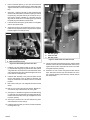
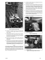
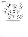
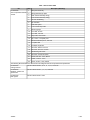
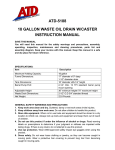
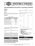
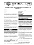
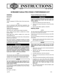
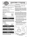
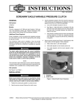
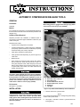
-J04654
REV. 2010-09-16
AUTOMATIC COMPRESSION RELEASE TOOLS
GENERAL
Kit Number
94648-08
Wear safety glasses or goggles while drilling. Flying debris
could result in serious eye injury. (00565b)
Models
is05443
For model fitment information, see the P&A Retail Catalog or
the Parts and Accessories section of www.harley-davidson.com
(English only).
Additional Parts Required
1
Separate purchase and installation of additional parts or
accessories is required for proper installation of this kit on your
model motorcycle.
2
Required tools include:
•
Cylinder head holding fixture, HD-39786
•
Cylinder head fasteners: cylinder head screw, 16480-92A
(2 required), cylinder head screw, 16478-85A (2 required),
exhaust mounting nuts, 7593 (2 required)
•
Valve spring compressor, HD-34736-B
•
Valve guide seal tools depending on year and type of cylinder head
•
Brass hammer
•
Other hand tools required include cutting fluid, tapping
fluid for aluminum, hand drill with 3/8 inch chuck, 15"
heavy-duty drill press or mill, 4 table clamps (to mount tool
plate to press) calipers, torque wrench in ft-lbs or Nm, 1/2"
12 point socket, 5/15" socket, set of allen wrenches, tap
handle, assembly lube.
4
3
7
6
The rider's safety depends upon the correct installation
of this kit. Use the appropriate service manual procedures.
If the procedure is not within your capabilities or you do
not have the correct tools, have a Harley-Davidson dealer
perform the installation. Improper installation of this kit
could result in death or serious injury. (00333a)
1.
2.
3.
4.
5.
6.
7.
Kit Contents
See Figure 7 and Table 1.
INSTALLATION
-J04654
5
Drill, 1.250 inch
Drill stop collar, 1.250 inch
Drill stop gauge
Socket head screw, 5/16 inch
Socket head screw, 1/4 inch
Dowel pin
Top plate
Figure 1. Top Plate and Drill Bit Stop Collar Installation
1.
Compressed air can pierce the skin and flying debris from
compressed air could cause serious eye injury. Wear
safety glasses when working with compressed air. Never
use your hand to check for air leaks or to determine air
flow rates. (00061a)
6
Remove valves from cylinder heads.
NOTE
Do not allow the threaded studs to damage the gasket sealing
surface of the cylinder head.
2.
See Figure 7 and Table 1. Mount a cylinder head to the
tooling plate (1).
1 of 5
3.
Place a head bolt spacer (7) over each stock head bolt
and lubricate threads and thrust faces, dowels and studs.
Tighten head bolts in a crisscross pattern to 10 ft-lbs (13.5
Nm).
4.
See Figure 1. Align the top plate (7) bolt and dowel holes
with the head hole pattern, Screamin' Eagle logo towards
the spark plug. This plate will only fit one way for the cylinder head it is being installed on. If the plate does not
align with the head, turn it over keeping the logo towards
the spark plug and install the cylinder head.
5.
Lubricate the two dowel pins (6) and insert in the top plate
and into the cylinder head.
6.
Apply lubricant to the two socket head screws (4 and 5).
Insert into their respective holes in the plate to the cylinder
head and tighten to 5 ft-lbs (6.8 Nm) .
is05445
3
is05444
1
1
2
2
1. Drill stop gauge
2. 0.875 inch drill
3. Drill stop collar
1. Drill bushing, 0.875 inch ID
2. Wide head socket screw
Figure 2. Install bushing for 0.875 inch drill
7.
Install the 1.25 inch drill stop collar (2) over the 1.25 drill
(1). Hold the drill stop gauge (3) with the short side marked
"Large Drill Set" over the flat end of the drill and the other
end up against the stop collar. Install and tighten set screw
in the collar to 5 ft-lbs (6.8 Nm).
8.
Install the drill assembly in the press and lower the drill
into the drill bushing of the top plate for alignment and
clamp the head down to the table to hold it in a centered
position.
9.
Drill at 350 to 600 rpm, use adequate lubricant and drill
slowly.
Figure 3. Install collar for 0.875 inch drill
14. Use the short side of the drill stop gauge (1) marked "Small
Drill Set" over the flat end of the drill and the other end up
against the stop collar. Install the set screw in the collar
and tighten to5 ft-lbs (6.8 Nm).
15. Drill down 1/4 inch at a time using lubricant then remove
chips. Drill down until the stop collar bottoms out on the
top of the drill bushing. When finished, carefully remove
the drill assembly.
10. Drill 1/4 inch at a time and remove all chips. Repeat process until the stop collar bottoms out on the plate.
11. See Figure 2. Lubricate the long 0.875 inch ID drill bushing
(1) and insert into the plate. Secure bushing with the lubricated wide head socket screw (2) and tighten the screw
to 5 ft-lbs (6.8 Nm).
12. See Figure 3. Remove the 1.25 inch drill from the press
and install the 0.875 inch drill (2).
13. Install the drill stop collar (3) to the chuck side of drill with
the flange at the top.
-J04654
2 of 5
20. Lubricate and slide transfer punch through the hole in the
jig and tap with a hammer.
is05446
21. See Figure 6. Set the short #13 drill bit (2) to be 2.5 inches
from its tip to the jaws of the drill chuck. Drill a hole slowly
using lubricant and remove chips after drilling 1/4 inch at
a time. Keep the drill going as straight as possible using
lubricant to keep the chips wet. Continue drilling until the
drill chuck comes close to making contact with the drill jig
then stop and remove the drill bit.
1
22. Install the long #13 drill bit. Use your calipers to set the
drill length to 4.5 inches from the drill chuck jaws to the
tip of the drill bit. Drill the hole slowly using lubricant and
remove chips after 1/4 inch at a time until the drill enters
the ACR cross hole drilled previously.
23. Carefully remove all metal chips and shavings with compressed air or by washing.
is05447
2
1. Tap, 12 mm
1
Figure 4. Tapping head for ACR
16. See Figure 4. Install the 12 mm tap (1) into the tap guide
extension and handle. Tighten extension set screw to 5
ft-lbs (6.8 Nm).
17. Lubricate tap and drilled hole. Tap hole turning clockwise
and reverse tap 1/2 turn after one full turn and continue
until the hole is fully tapped. Apply cutting fluid liberally
each time you reverse the tap.
1. Exhaust Port Drill Jig
2. Stock exhaust nut
Figure 5. Install Drill Jig
is05448
18. Remove head from plates. Lube and install cylinder head
holding fixture and clamp tool in vise with access to
exhaust port.
19. See Figure 5. If you are working with the rear head, install
the rear exhaust port drill jig (1). Use two lubricated stock
exhaust nuts to fasten the jig to the cylinder head. Hold
the jig against the exhaust port and finger tighten the nuts
snug. Alternately tighten the nuts to 10 ft-lbs (13.5 Nm).
NOTE
In the following step you will need to tap the transfer punch
hard enough and straight enough to leave a punch mark about
0.030 inch deep so the drill will not slide off the wall of the
exhaust port. To check this depth you can use calipers to check
the amount the transfer punch is out of the drill jig before and
after you have tapped it with a hammer.
-J04654
1
2
1. Exhaust port drill jig
2. 0.875 inch drill
Figure 6. Drill through to ACR cross hole
3 of 5
SERVICE PARTS
is05462
3
19
1
4
23
21
22
7
17
5
2
9
8
20
12
15
11
14
18
10
6
16
13
Figure 7. Service Parts Kits: Automatic Compression Release Tools
-J04654
4 of 5
Table 1. Service Parts Table
Kit
Item
Description (Quantity)
Kit 94648-08
Auto Compression Release
Tool Kit
1
Base plate assembly
2
Drill jig assembly top plate
3
Rear exhaust assembly drill jig
4
Front exhaust assembly drill jig
5
7/8 inch drill bushing
6
Tap extension
7
Head bolt spacer
8
1.25 inch drill stop collar
9
Drill stop gauge
10
Form drill, 7/8 inch
11
Form drill, 1.25 inch
12
Stop collar, 7/8 inch drill
13
Tap, 12 mm, 1.25 spiral point
14
Machined transfer punch, 3/16 inch
15
#13 jobber drill
16
#13 Taper length drill
17
Set screw, 3/8-24 x 1/4 inch
18
Set screw, 5/16-18 x 1/4 inch
19
Drill bushing lock screw
20
Set screw, 1/4-28 x 3/16 inch
21
Screw, 5/16-18 x 1 inch, SHCS
22
Dowel, 9.5 mm x 1 inch
23
Screw, 1/4-20 x 1 inch, SHCS
The following kits break down the above items into catagories that can be purchased as separate kits.
Kit 94049-09
Cutting Tools Kit
This kit contains items 6, 9, 10, 11, 13, 14, 15 and 16
Kit 94050-09
Bushings, Collars and
Spacers Kit
This kit contains items 5, 7, 8, 12, 19 and 22
Kit 94051-09
Drill Jigs Kit
This kit contains items 3 and 4
-J04654
5 of 5