1
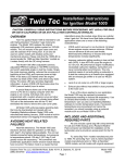
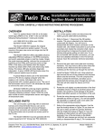
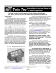
Twin Tec User Instructions for TCFI Log Software CAUTION: CAREFULLY READ INSTRUCTIONS BEFORE PROCEEDING. THE USER IS ASSUMED TO BE FAMILIAR WITH MICROSOFT WINDOWS AND PC OPERATION. OVERVIEW TCFI Log software runs under Microsoft Windows 98/ME/XP/Vista. This software allows TCFI fuel injection controller users to view real time engine data during dyno tuning, download and display data logged by the unit including operating statistics, and to control certain engine functions. An optional USB Interface or PC link cable is required to connect to the existing four terminal Deutsch style data link connector on the H-D wiring harness. The new Twin Tec USB Interface P/N USB-INTF provides PC connectivity for all of our engine controls (ignition and fuel injection systems) and eliminates the requirement for multiple cables or a separate USB adapter if your laptop is not equipped with an RS-232 serial port (9 pin male D-sub connector). The USB Interface is compatible with Windows 98/ME/XP/Vista. If you do not have the new USB interface, you will require the original RS-232 PC link cable P/N TCFI-C also used with our new TC88A ignition. Please note that the TC88C PC link cable used with the earlier TC88 ignition will not function. The two types of PC link cables have identifying labels, but otherwise appear similar. However, the electrical connections are different and the two cables types cannot be interchanged. After TCFI Log is launched, the main screen appears blank. You have multiple display options. You can display real time engine data on an instrument panel type screen by using the View Real Time Data command on the View menu. You can display data logged by the TCFI unit on a chart recorder type screen. You can also view engine operating statistics logged by the TCFI unit. Data logged by the TCFI unit must be downloaded before it can be displayed, by using the Download Data From TCFI command on the Communications menu. Once data has been downloaded, it is automatically displayed on a chart recorder type screen. You can view the engine operating statistics by using the View Statistics command from the View menu. You can save this data by using the Save File command from the File menu. You can display a previously saved data file by first using the Open File command on the File menu and then using the View Chart or View Statistics commands on the View menu. TCFI Log is compatible with all TCFI Gen II units (including the new TCFI IID version) and TCFI units with Rev 5.0 or higher firmware. A sample data file (Sample.log) is included in the program folder. PC REQUIREMENTS If you are using the new Twin Tec USB Interface (P/N USB-INTF), refer to the supplied instructions for details. No additional hardware is required. The original PC link cable connects to an RS232 serial port by means of a female 9 pin D-sub connector. Data transfer occurs at 56 kBaud. The high baud rate limits the maximum cable length and the use of an extension cable is not recommended. Due to the cable length limitation and the need for portable access, a laptop PC is recommended. The PC must have a free serial port (COM1-255) with a standard 9 pin male D-sub connector. If your laptop does not include a serial port, you can use a USB adapter. However, not all USB adapters will work correctly with our PC link cables. Most of the inexpensive USB adapters are intended for interfacing Palm Pilot type devices and do not support all the signals required by our PC link cables. We sell and recommend a low cost USB adapter (P/N USBG-232) that has been tested with a wide range of system configurations. The USBG-232 adapter comes with correct and updated driver files on CDROM. After installation the USBG-232 adapter will usually appear as COM5. We recommend a laptop with Pentium processor and super VGA display (SVGA with 1024 x 768 pixel resolution) running Windows 98/ME/XP/Vista. Data chart display is graphics intensive and a high speed Pentium processor is recommended. Processors slower than 300 MHz will exhibit sluggish program loading and response. The PC must have a CDROM drive for program loading. TCFI Log includes print commands to print downloaded data. The program has been tested with Daytona Twin Tec LLC, 933 Beville Road, Suite 101-H, S. Daytona, FL 32119 (386) 304-0700 www.daytona-twintec.com Page 1 TCFI Log 3/2007 Hewlett-Packard laser and inkjet printers and Epson inkjet printers. We recommend using a color inkjet printer. Turn the ignition key and engine run/stop switches on to provide power to the TCFI unit. Do not start the engine if you want to download data. SOFTWARE INSTALLATION If the TCFI unit has been removed from the motorcycle, you can do bench top programming by using an adapter harness (P/N TCFI-ADAPT) that includes a small 12 volt DC power supply. The software is supplied on CDROM media or in the form of a compressed file downloaded from our website. The installation process uses InstallShield. This industry standard installer is based the new Microsoft Windows Installer service that greatly reduces potential problems such as version conflicts and allows for application self-repair. Since Windows 98 systems did not originally include the Windows Installer service, the required installer software is included in the distribution media. Before proceeding with installation, shutdown any other applications that may be running. For Windows Vista, you must disable the User Account Control (UAC) during installation. If you are not familiar with the UAC, please refer to the Vista UAC Tech Note on our website's Tech FAQ for details. Use the Windows Explorer or the Run command from the Windows Start Menu to launch setup.exe in the TCFI_Log folder on the CDROM or the setup.exe file downloaded from our website. InstallShield will install the software in an appropriate folder under Program Files. Once InstallShield has completed the installation, TCFI Log will appear on the Windows Start Menu. You can then launch it just as you would any other Windows program. TCFI Log requires the Monospace 821 BT fixed pitch printer font in order to properly align columns when printing. The Monospace 821 BT font is included in the distribution media and automatically copied to your Windows Fonts folder during installation. A backup copy is also placed in the program folder. If you accidentally delete this font, use the Install New Font command from the Fonts folder File menu. The filename associated with Monospace 821 BT is monos.ttf. COM1 is used as the default port. If you are using a different COM port, use the Port Setup command on the Communications Menu. REAL TIME ENGINE DATA DISPLAY When the engine is running, you can display real time engine data on an instrument panel type screen by using the View Real Time Data command on the View menu. Please note that real time engine data cannot be directly saved by means of the TCFI Log program. However, this data is constantly being logged by the TCFI unit and can be downloaded (for example at the end of series of dyno runs). Real time engine data is displayed on an instrument panel type layout with round tach and speedometer gauges and bar graph type gauges for most other parameters. Barometric pressure (In-Hg), any diagnostic codes, status of the user output, and status messages are displayed in additional windows. If the engine is not running most values will appear as zero. Displayed parameters include: RPM – engine crankshaft RPM (numeric value displayed beneath gauge) VSS – vehicle speed in MPH (numeric value displayed beneath gauge) TPS – throttle position (0 to 100%) MAP – manifold pressure in In-Hg (29.92 In-Hg corresponds to atmospheric pressure) ET – engine cylinder head temperature (deg C) TCFI CONNECTION IAT – intake air temperature (deg C) If you are using the new USB Interface, refer to the supplied instructions for details. No additional hardware is required. BAT – battery voltage IAC – idle air control stepper motor position (higher number means more idle air) If you are using the original RS-232 PC link cable, connect the cable to the OE data link connector and PC serial port. The OE data link uses a four terminal Deutsch connector that is usually found near the TCFI unit. Daytona Twin Tec LLC, 933 Beville Road, Suite 101-H, S. Daytona, FL 32119 (386) 304-0700 www.daytona-twintec.com Page 2 TCFI Log 3/2007 Figure 1 – Real Time Engine Data Display AFR – the air/fuel ratio bar graph has dual pointers. The yellow pointer on the left side is the air/fuel ratio command (from AFR table). The white pointer on the right side is the actual air/fuel ratio based on the exhaust gas oxygen sensor reading. Note that the value will remain near 10 until the sensor has warmed up. Front and rear cylinder AFR values are displayed for TCFI IID units. BLM – block learn multiplier (main fuel table correction factor based on exhaust gas oxygen sensor feedback, shown as percent value from 75-125%). Front and rear cylinder BLM values are displayed for TCFI IID units. IDLE TPS DISPLAY You can check the idle TPS adjustment by using the View Idle TPS command on the View menu. Turn the run/stop switch on, but do not start the engine when using this function. Idle TPS volts are displayed on the TPS bar graph gauge. All other instrument values will appear as zero. With the throttle fully closed, verify that the gauge display is between .30 to .80 volts for TCFI IID units or between .35 to .45 volts for all other TCFI and TCFI II units. If the value is outside this range, you will have to adjust the TPS sensor. For optimum performance, adjust the TPS sensor to .40 volts. FRONT INJ PW, REAR INJ PW – injector pulse width in milliseconds FRONT ADV, REAR ADV – ignition advance in degrees BTDC Daytona Twin Tec LLC, 933 Beville Road, Suite 101-H, S. Daytona, FL 32119 (386) 304-0700 www.daytona-twintec.com Page 3 TCFI Log 3/2007 DATA LOGGING CHART DISPLAY You can also display data logged by the TCFI unit on a chart recorder type screen. Data logged by the TCFI unit must be downloaded before it can be displayed, by using the Download Data From TCFI command on the Communications menu. Once data has been downloaded, it is automatically displayed. The last data logged will appear at the right end of the chart. You can save the data by using the Save File command from the File menu. You can display a previously saved data file by first using the Open File command on the File menu and then using the View Chart command on the View menu. Note that TCFI data files use a .log extension. You should create a separate folder to store these files. You have a range of capabilities for analyzing downloaded data displayed in the chart recorder format. You can select two parameters for display. Trace 1 is displayed in red with its Y axis legends on the left side of the chart. Trace 2 is displayed in green with its Y axis legends on the right side of the chart. The X axis is always elapsed time. You can select from one of three time scales. You can use the scroll bar to move the chart display window in terms of elapsed time. If you hold the left mouse button down within the chart area, a cursor line appears. The exact values of the parameters displayed on trace 1 and trace 2 and the elapsed time appear in windows above the chart. If you want to analyze the elapsed time between two events (for example the time required to accelerate from 0 to 60 MPH), you can move the cursor to the first event and then click on the Reset Time Display button. You can print the displayed chart to any Windows printer by clicking on the Print button (a color inkjet printer is recommended for best results). Data parameters include: RPM – engine crankshaft RPM VSS – vehicle speed in MPH MAP – manifold pressure in In-Hg (29.92 In-Hg corresponds to atmospheric pressure) TPS – throttle position (0 to 100%) AFR – air/fuel ratio based on the exhaust gas oxygen sensor reading (10:1 to 20:1). Front and rear cylinder AFR values can be displayed for data logged by TCFI IID units. BLM – block learn multiplier (main fuel table correction factor based on exhaust gas oxygen sensor feedback, shown as percent value from 75-125%). Front and rear cylinder BLM values can be displayed for data logged by TCFI IID units. IAC – idle air control stepper motor position (higher number means more idle air) IAT – intake air temperature (deg C) ET – engine cylinder head temperature (deg C) FRONT INJ, REAR INJ – injector pulse width in milliseconds FRONT ADV, REAR ADV – ignition advance in degrees BTDC BAT – battery voltage USER – user output displayed as digital (on/off) signal. On means that the output is grounded. Additional data is displayed at the lower right side of the screen. This data includes: Baro – barometric pressure in In-Hg. Diagnostic Code – normally blank unless a diagnostic code is set. Refer to the TCFI installation instructions for details. Engine Status – based on engine temperature and open/closed loop AFR Log Interval – the actual data logging interval in seconds The TCFI data buffer stores the last 1600 data points. With a nominal data logging interval of 0.50 seconds, this corresponds to 13.3 minutes of data. You can set higher or lower data logging intervals by means of the PC Link TCFI software Module Parameters screen. Data logging intervals of 0.5-1.0 seconds are suitable for on-road tests; a shorter interval of 0.10 seconds is recommended for dyno tuning. You can clear the data within the TCFI by using the Clear TCFI Data Buffer command from the Communications menu. If you change the data logging interval, you should also clear the TCFI data buffer. Daytona Twin Tec LLC, 933 Beville Road, Suite 101-H, S. Daytona, FL 32119 (386) 304-0700 www.daytona-twintec.com Page 4 TCFI Log 3/2007 Figure 2 – Data Logging Chart Display The following additional functions are available from the Edit menu: BLM Cell Display – shows the active cell in terms of RPM and TPS percent at the cursor position. TPS percent is compensated for idle air. This function is useful for determining what fuel table cell is active at any given point in time. Gear Ratio Display – shows the calculated gear ratio (RPM/KPH) at the cursor position. This function is useful for determining the 6th gear ratio required for Module Parameter setup in PC Link TCFI IID for 2007 models with six speed transmissions and a 6th gear indicator light. Units Selection – allows selection of MPH or KPH units for vehicle speed display. IAC MANUAL OVERRIDE The IAC Manual Override command on the Communications menu allows you to manually override the idle air control stepper motor position while the engine is running. This command is primarily used to calibrate larger aftermarket throttle bodies, but can also be used as a diagnostic aid. Daytona Twin Tec LLC, 933 Beville Road, Suite 101-H, S. Daytona, FL 32119 (386) 304-0700 www.daytona-twintec.com Page 5 TCFI Log 3/2007 USER OUTPUT MANUAL OVERRIDE The User Output Manual Override command on the Communications menu allows you to manually override the user output on TCFI units. This command can be used as a diagnostic aid to test accessory systems connected to the user output. OPERATING STATISTICS You can also display engine operating statistics logged by the TCFI unit. Data logged by the TCFI unit must be downloaded before it can be displayed, by using the Download Data From TCFI command on the Communications menu. Once data has been downloaded, you can use the View Statistics command from the View menu. You can save this data by using the Save File command from the File menu. You can display a previously saved data file by first using the Open File command on the File menu and then using the View Statistics command on the View menu. Note that TCFI data files use a .log extension. You should create a separate folder to store these files. ID represents the firmware identification. This field typically includes the manufacturer (Twin Tec), model number, program revision and author's initials, and date. Note that the date is not a manufacturing date code, just the date for the particular firmware release. Elapsed time is displayed for 13 RPM bands from idle to 6999 RPM. Note that elapsed time data is rounded off during each engine run, so the sum of the elapsed time figures may not precisely match the total hours. The program also displays the maximum engine RPM, time at the RPM limit (in seconds for better resolution) and the number of engine starts. Clicking on the Print Statistics button prints a report. When you click on this button, a small data entry screen pops up and allows you to add a serial number or comment that will appear on the printout. You can also use the Print command from the File menu. You can clear the statistics data within the TCFI by using the Clear Statistics Data command from the Communications menu. The first time you use this command, you will be prompted for a password. Your dealer can supply you with the required password. The data is fairly self-explanatory. Total hours represents the total time that the engine was running. Figure 3 - Operating Statistics Display Daytona Twin Tec LLC, 933 Beville Road, Suite 101-H, S. Daytona, FL 32119 (386) 304-0700 www.daytona-twintec.com Page 6 TCFI Log 3/2007 Figure 4 - Operating Statistics Histogram Chart Historical diagnostic codes are only applicable to TCFI Gen II units and TCFI units with Rev 6.0 or higher firmware. Any historical diagnostic codes logged by the TCFI unit are listed along with the number of trips (engine start cycles) since the individual code was last logged. Codes are automatically cleared after 50 trips. Customers are often confused about the meaning of the term “trips.” This is an industry standard terminology. If a code shows 40 trips, it means that the code was set 40 engine start cycles ago, not that the code has been set 40 times. Refer to the TCFI instructions for further information about diagnostic codes. You can clear historical diagnostic codes by using the Clear Historical Diagnostic Codes command from the Communications menu. The elapsed time data in the various RPM bands can be displayed in the form of a histogram chart by clicking on the Histogram button. Color coding of the bars helps to interpret the data. The idle RPM band is blue, normal operating RPM bands are green and high RPM bands are yellow and red. The chart is automatically scaled for best display. You can print the chart along with a complete statistics report by clicking on the Print Chart button. IMPORTING DATA INTO EXCEL Data files saved from TCFI Log are in comma delimited ASCII format. You can easily import a data file into other programs such as Microsoft Excel for further analysis. You can also view data files with a text editor such as Windows WordPad. To import a data file into Excel: 1. Start Excel. In the File Open dialog box, select Files of type: All Files (*.*). Then browse for the data file. 2. The Text Import Wizard appears. For step 1, select delimited file type. For step 2, select comma delimiter. For step 3, select general column data format. Then click on Finish. 3. You can then format the data and save the spreadsheet as an Excel file. Daytona Twin Tec LLC, 933 Beville Road, Suite 101-H, S. Daytona, FL 32119 (386) 304-0700 www.daytona-twintec.com Page 7 TCFI Log 3/2007 TROUBLESHOOTING FLOWCHART Follow the troubleshooting flowchart below. Experience has shown that most communication problems are user error or PC compatibility issues. Troubleshooting Flowchart STARTING POINT IS RS-232 TIMEOUT ERROR MESSAGE DISPLAYED WHEN ATTEMPTING DOWNLOAD OR UPLOAD? YES NO FOR MISC PROBLEMS, CALL TECH SUPPORT. CYCLE ENGINE RUN/STOP SWITCH. VERIFY CHECK ENGINE LIGHT ILLUMINATED. IS PROBLEM FIXED? YES NO DONE USE WINDOWS DEVICE MANAGER TO VERIFY THAT CORRECT COM PORT IS SELECTED. IS PROBLEM FIXED? YES NO FIRST TIME USE OF USB ADAPTER THAT WAS SUPPLIED BY A THIRD PARTY (NOT SOLD AS PART OF OUR SYSTEM)? DONE YES NO USB ADAPTER MAY BE INCOMPATIBLE. REPLACE USB ADAPTER (REFER TO INSTRUCTIONS). IS PROBLEM FIXED? YES DONE NO OTHER SOFTWARE ON PC THAT USES COM PORT SUCH AS PALM PILOT OR DIGITAL CAMERA? YES DISABLE OTHER SOFTWARE. PALM PILOT - MAKE SURE HOT SYNC ICON DOES NOT APPEAR IN SYSTEM TRAY. IS PROBLEM FIXED? NO USE ANOTHER PC OR UNINSTALL OFFENDING SOFTWARE. IN SOME CASES YOU MAY HAVE TO RELOAD WINDOWS. CALL TECH SUPPORT FOR FURTHER INFORMATION. NO CALL TECH SUPPORT YES DONE Daytona Twin Tec LLC, 933 Beville Road, Suite 101-H, S. Daytona, FL 32119 (386) 304-0700 www.daytona-twintec.com Page 8 TCFI Log 3/2007