1
Issue Date:
2010-10-05
Page 1 of 8
Report Reference #
E141136-A205-UL
UL TEST REPORT AND PROCEDURE
Standard:
CCN:
UL 60950-1, 2nd Edition, 2007-03-27 (Information Technology
Equipment - Safety - Part 1: General Requirements)
CSA C22.2 No. 60950-1-07, 2nd Edition, 2007-03 (Information
Technology Equipment - Safety - Part 1: General Requirements)
Information Technology Equipment Including Electrical Business
Equipment
NWGQ, NWGQ7
Product:
Model:
Rating:
L2 Fast Ethernet Standalone Switch
ECS3510-26T
100-240Vac, 50-60Hz, 0.3A
Applicant Name and Address:
ACCTON TECHNOLOGY CORP
1 CREATION 3RD RD
SCIENCE-BASED INDUSTRIAL PARK
HSINCHU
300 TAIWAN
Certification Type:
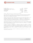
This is to certify that representative samples of the products covered by this Test Report have been investigated in accordance with the
above referenced Standards. The products have been found to comply with the requirements covering the category and the products are
judged to be eligible for Follow-Up Service under the indicated Test Procedure. The manufacturer is authorized to use the UL Mark on
such products which comply with this Test Report and any other applicable requirements of Underwriters Laboratories Inc. ('UL') in
accordance with the Follow-Up Service Agreement. Only those products which properly bear the UL Mark are considered as being
covered by UL's Follow-Up Service under the indicated Test Procedure.
The applicant is authorized to reproduce the referenced Test Report provided it is reproduced in its entirety.
Any information and documentation involving UL Mark services are provided on behalf of Underwriters Laboratories Inc. (UL) or any
authorized licensee of UL.
Prepared by:
Jimmy Tsao
Underwriters Laboratories Inc.
Reviewed by:
Rick Li
Underwriters Laboratories Inc.
Copyright © 2010
Created by UL Document Assembler 2010-10-20 00:43:37 -05:00
Issue Date:
2010-10-05
Page 2 of 8
Report Reference #
E141136-A205-UL
Supporting Documentation
The following documents located at the beginning of this Procedure supplement the requirements of this Test
Report:
A. Authorization - The Authorization page may include additional Factory Identification Code markings.
B. Generic Inspection Instructions i. Part AC details important information which may be applicable to products covered by this Procedure.
Products described in this Test Report must comply with any applicable items listed unless otherwise
stated in the body of this Test Report.
ii. Part AE details any requirements which may be applicable to all products covered by this Procedure.
Products described in this Test Report must comply with any applicable items listed unless otherwise
stated in the body of each Test Report.
iii. Part AF details the requirements for the UL Certification Mark which is not controlled by the technical
standard used to investigate these products. Products are permitted to bear only the Certification
Mark(s) corresponding to the countries for which it is certified, as indicated in each Test Report.
Product Description
- Consists of a Certificated build-in PSU, electric components mounted on PWB, then all housed in a metal of
bottom and cover for enclosure, then secured together by screws.
Model ECS3510-26T unit included RJ-45 ports x 26 ports, SFP ports x 4, console ports x 1.
Model Differences
N/A
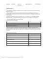
Technical Considerations
Equipment mobility : movable
Connection to the mains : pluggable A
Operating condition : continuous
Access location : operator accessible
Over voltage category (OVC) : OVC II
Mains supply tolerance (%) or absolute mains supply values : +6%, -10%
Tested for IT power systems : No
IT testing, phase-phase voltage (V) : N/A
Class of equipment : Class I (earthed)
Created by UL Document Assembler 2010-10-20 00:43:37 -05:00
Issue Date:
2010-10-05
Page 3 of 8
Report Reference #
E141136-A205-UL
Considered current rating (A) : 20 A
Pollution degree (PD) : PD 2
IP protection class : IP X0
Altitude of operation (m) : up to 2000m
Altitude of test laboratory (m) : Below 2000m
Mass of equipment (kg) : 1.76 Kg
The product was submitted and evaluated for use at the maximum ambient temperature (Tma)
permitted by the manufacturer’s specification of: 50 degree C
The means of connection to the mains supply is: Pluggable A, Detachable power cord
The product is intended for use on the following power systems: TN
The equipment disconnect device is considered to be: Appliance inlet,
The class of laser product is: Class 1 (I)
The product was investigated to the following additional standards: EN 60950-1:2005 + A11:2009
(which includes all European national differences, including those specified in this test report).
The following circuit locations (with circuit/schematic designation) were investigated as a limited
power source (LPS): RJ45 Ports (Transfer electrical singal ) and Optical Transceiver (Transfer
optical singal ) based on circuit diagrams, functions, features, characteristics analysis and connector
overload meausrement results.
The following are available from the Applicant upon request: Installation (Safety) Instructions /
Manual
The power supply in this equipment was: Investigated to an earlier edition/amendment of IEC/UL
60950-1, 1st edition. As part of the investigation of this product, the power supply and its test report
were reviewed and found to comply with IEC/UL 60950-1, 2nd edition.
Additional Information
- The label is a draft of an artwork for marking plate pending approval by National Certification Bodies and it
shall not be affixed to products prior to such an approval.
- This report has been to amendment, due to upgrade IEC/ EN standard to IEC 60950-1:2005; 2nd Edition /
Created by UL Document Assembler 2010-10-20 00:43:37 -05:00
Issue Date:
2010-10-05
Page 4 of 8
Report Reference #
E141136-A205-UL
EN 60950-1:2006+A11: 2009.
- Only limited tests were performed on model ECS3510-26T because of similarity in construction to Model
ES-3026 , see Report no. E141136-A194-CB previously evaluated unit. Except for metal shape and model
designation.
Markings and instructions
Clause Title
Inter-connecting cables
- External detachable
Safety Instructions Rack Mount
Marking or Instruction Details
Listee's Name and Part number (Marking or Instruction)
"Rack Mount Instructions - The following or similar rack-mount instructions
are included with the installation instructions:
A) Elevated Operating Ambient - If installed in a closed or multi-unit rack assembly,
the operating ambient temperature of the rack environment may be greater than
room ambient. Therefore, consideration should be given to installing the equipment
in an environment compatible with the maximum ambient temperature (Tma)
specified by the manufacturer.
B) Reduced Air Flow - Installation of the equipment in a rack should be such that
the amount of air flow required for safe operation of the equipment is not
compromised.
C) Mechanical Loading - Mounting of the equipment in the rack should be such that
a hazardous condition is not achieved due to uneven mechanical loading.
D) Circuit Overloading - Consideration should be given to the connection of the
equipment to the supply circuit and the effect that overloading of the circuits might
have on overcurrent protection and supply wiring. Appropriate consideration of
equipment nameplate ratings should be used when addressing this concern.
E) Reliable Earthing - Reliable earthing of rack-mounted equipment should be
maintained. Particular attention should be given to supply connections other than
direct connections to the branch circuit (e.g. use of power strips)."
Power rating - Ratings
Ratings (voltage, frequency/dc, current)
Power rating Company identification
Power rating -
Listee's or Recognized company's name, Trade Name, Trademark or File
Number
Model Number
Model
Telecom type
connectors not used for
For telecommunication type connectors and terminals not used for
telecommunication
connection to the telecommunication network should be provided with a marking
purposes
identifying the specific function or circuit characteristic the connector or terminal is
Created by UL Document Assembler 2010-10-20 00:43:37 -05:00
Issue Date:
2010-10-05
Page 5 of 8
Report Reference #
E141136-A205-UL
used for Connector RJ45.
Service Manual
See enclosure 6-01
Special Instructions to UL Representative
N/A
Production-Line Testing Requirements
Electric Strength Test Special Constructions - Refer to Generic Inspection Instructions, Part AC for
further information.
Model
Component
Removable
Parts
Test probe location
V
rms
V dc
Test Time,
s
--
--
--
--
--
--
--
Earthing Continuity Test Exemptions - This test is not required for the following models:
-Electric Strength Test Exemptions - This test is not required for the following models:
-Electric Strength Test Component Exemptions - The following solid-state components may
disconnected from the remainder of the circuitry during the performance of this test:
-Sample and Test Specifics for Follow-Up Tests at UL
Model
--
Component
--
Material
--
Test
--
Created by UL Document Assembler 2010-10-20 00:43:37 -05:00
Sample(s)
--
Test
Specifics
--
Issue Date:
2010-10-05
Page 6 of 8
Report Reference #
E141136-A205-UL
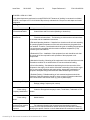
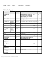
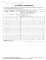
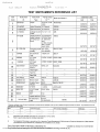
TABLE: List of Critical Components
Object/part No.
Manufacturer/
trademark
--
type/model
technical data
CCN
--
ELBZ
02. Enclosure Material
--
--
--
--
03. Power supply unit
Universal Micro
electronics Co.,Ltd
Rong Feng Industrial
Co Ltd
Jowle Technology Co
Ltd
WELI SHENG
TERMINAL
INDUSTRIAL CO
LTD
--
UP0131A-05
SS-120
Maximum 4.5m and Minimum 1.5m, long, Type
SJT, SVT or SPT-2, 18 AWG. One end terminates
in NEMA 5-15P with min. 125Vac, 10A,the other
end with an appliance coupler.
Steel, 0.6 mm minimum thickness, see enclosure
ID7-01 and 7-02 for the details.
Input: 100-240Vac; 47-63Hz; 0.4A. Output : 5Vdc,3
A
250Vac, 10A
Marks of
Conformity
UL
AXUT2
UL
A3961H02-3P
250Vac, 5A
ECBT2
UL
PX-I39601
250V,7A
ECBT2
UL
--
AVLV2
UL
---
-RJ-45, console
port,
ZPMV2
DUXR2
UL
UL
--
Optical fiber port
VW-1 or FT-1, minimum 300Vac, 18AWG,
minimum 80 degree C.
Minimum V-1, 105 degree C
27 ports
Provided ( including console port) Copper alloy pins
housed in bodies of plastic rated V-2 min.
2 provided
--
--
--
--
min V-2.
QMFZ2
UL
--
--
VW-1 or FT-1; min 30 V, 50 degee C.
AVLV2
UL
--
--
FEP, PTFE, PVC, TFE, neoprene, polyimide
--
--
01. Power supply Cord
(Optional)
04. AC Inlet
05. AC Connector
05a. AC Connector
(Alternate)
06. Wiring, internal
(Primary)
07. Printed wiring board
08. Connectors and
Receptacles (secondary
ELV/SELV circuits)
08a. Connectors and
Receptacles (secondary
ELV/SELV circuits)
(Alternate)
09. Internal Plastic Part
Materials
10. Wiring, internal
(secondary ELV/SELV
circuits)
10a. Wiring, internal
(secondary ELV/SELV
circuits) (Alternate)
Created by UL Document Assembler 2010-10-20 00:43:37 -05:00
QQGQ2, QQGQ8 UL
Issue Date:
2010-10-05
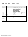
Object/part No.
11. Earthing and
Bonding
12. Insulating
Tubing/Sleeving
13. Insulation sheet (
between Power supply
and metal chassis)
14. Interconnecting
cables (Optional)
14a. Interconnecting
cables (Optional)
(Alternate)
15. Optical Transceiver
(Optional)
16. Label
Page 7 of 8
Report Reference #
E141136-A205-UL
Manufacturer/
trademark
--
type/model
technical data
CCN
--
AVLV2
--
-FR1
UZFT2, YDPU2,
YDTU2
QMFZ2
UL
Sabic Innovative
Plastics Chian
CO.LTD.
--
Min. No. 18 AWG, insulated with green/yellow
color, one end mechanically secured and soldered
to the ground pin of the Appliance Inlet, the other
end terminated in a doublecrimped closed-loop or
spade type terminal and secured to metal
chassis/frame by a screw with engaged two
complete threads and a star washer.
FEP, PTFE, PVC, TFE, neoprene, polyimide or
marked VW-1.
94VTM-0,min 0.25mm thickness, see enclosure
ID7-04 for the details.
AVLV2
UL
--
--
Minimum 50 degree C, 30 V, maximum 3.05 m
long, VW-1 or FT-1.
CMR, CMG, CM. CMX. CMUC or CMH.
DUZX
UL
--
--
Laser Class I, 3.3 Vdc.
NWGQ2
UL
--
--
--
PGDQ2 or PGJI2 UL
--
Created by UL Document Assembler 2010-10-20 00:43:37 -05:00
Marks of
Conformity
UL
UL
Issue Date:
2010-10-05
Page 8 of 8
Report Reference #
E141136-A205-UL
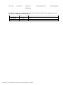
Enclosures
Type
Supplement Id
Description
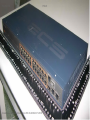
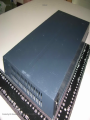
Photographs
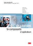
3-01
Overall view-1 for Models ECS3510-26T
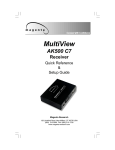
Photographs
3-02
Overall view-2 for Model ECS3510-26T
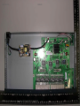
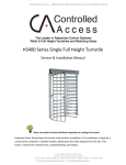
Photographs
3-03
Internal view for Model ECS3510-26T
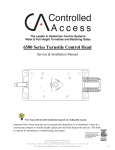
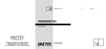
Manuals
6-01
Manual for mounting mean, Model ECS3510-26T
Miscellaneous
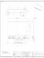
7-01
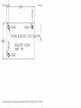
Cover enclosure drawing for Model ECS3510-26T
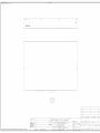
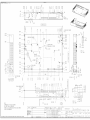
Miscellaneous
7-02
Bottom enclosure drawing for Model ECS3510-26T
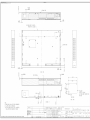
Miscellaneous
7-04
Insulation sheet drawing for Model ECS3510-26T between power
board and metal enclosure
Diagrams
Schematics + PWB
Created by UL Document Assembler 2010-10-20 00:43:37 -05:00
File E141136
Created by UL Document Assembler 2010-10-20 00:43:37 -05:00
PHO-01
File E141136
PHO-02
Created by UL Document Assembler 2010-10-20 00:43:37 -05:00
File E141136
PHO-03
Created by UL Document Assembler 2010-10-20 00:43:37 -05:00
File E141136
MAN-01
Created by UL Document Assembler 2010-10-20 00:43:37 -05:00
File E141136
MAN-01
Created by UL Document Assembler 2010-10-20 00:43:37 -05:00
File E141136
Created by UL Document Assembler 2010-10-20 00:43:37 -05:00
MIS-01
File E141136
Created by UL Document Assembler 2010-10-20 00:43:37 -05:00
MIS-01
File E141136
Created by UL Document Assembler 2010-10-20 00:43:37 -05:00
MIS-02
File E141136
Created by UL Document Assembler 2010-10-20 00:43:37 -05:00
MIS-02
File E141136
MIS-04
Created by UL Document Assembler 2010-10-20 00:43:37 -05:00
Issue Date:
2010-10-05
Page 1 of 2
Report Reference #
E141136-A205-UL
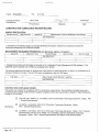
Test Record
Test Record No. 1
-- The manufacturer submitted representative production samples of L2 Fast Ethernet Standalone Switch
Model ECS3510-26T.
-- Only limited tests were performed on models ECS3510-26T because of similarity in construction to
Model ES-3026 , see Report no. E141136-A194-UL previously evaluated unit. Except for metal shape and
model designation.
-- All tests were conducted by Accton Technology Corp., No. 1 Creation Rd. III, Sciencebased Industrial
Park, Hsinchu 30077, Taiwan and witnessed by a member of the UL staff under the WTDP program.
-- Test results reported relate only to the items tested.
The following tests were conducted:
Test
Testing Location/Comments
End Product Reference Page
General Guidelines
Protective Bonding II (2.6.3.4, 2.6.1)
Test results are valid only for the tested equipment. These tests are considered representative of the
products covered by this Test Report. The test methods and results of the above tests have been reviewed
and found to be in accordance with the requirements in the Standard(s) referenced at the beginning of this
Test Report.
The following tests were waived:
Test
Rationale for Waiving
Input: Single-Phase (1.6.2)
Refer to Report no. E141136-A194UL
Heating (4.5.1, 1.4.12, 1.4.13)
Refer to Report no. E141136-A194UL
Electric Strength (5.2.2)
Refer to Report no. E141136-A194UL
Abnormal Operation (5.3.1 - 5.3.9)
Refer to Report no. E141136-A194UL
Overload of Operator Accessible Connector (5.3.7)
Refer to Report no. E141136-A194UL
Created by UL Document Assembler 2010-10-20 00:43:37 -05:00
Issue Date:
2010-10-05
Page 2 of 2
Report Reference #
E141136-A205-UL
Test Record
The following supplements are provided as a part of this Test Record. NOTE: These supplements are only
available to the Applicant via the CDA system.
Type
Supplement Id
Description
Attachment
2-01
CRD
Datasheet
2-02
Datasheet
Created by UL Document Assembler 2010-10-20 00:43:37 -05:00
File E141136
01-ATT-01
Created by UL Document Assembler 2010-10-20 00:43:37 -05:00
File E141136
01-ATT-01
Created by UL Document Assembler 2010-10-20 00:43:37 -05:00
File E141136
01-ATT-01
Created by UL Document Assembler 2010-10-20 00:43:37 -05:00