1
Issue Date:
2010-03-05
Page 1 of 15
Report Reference #
E135494-A59-UL
2012-03-21
UL TEST REPORT AND PROCEDURE
Standard:
Certification Type:
CCN:
Complementary CCN:
Product:
Model:
UL 60950-1, 2nd Edition, 2007-03-27 (Information Technology
Equipment - Safety - Part 1: General Requirements)
CSA C22.2 No. 60950-1-07, 2nd Edition, 2007-03 (Information
Technology Equipment - Safety - Part 1: General Requirements)
Component Recognition
QQGQ2, QQGQ8 (Power Supplies for Information Technology
Equipment Including Electrical Business Equipment)
QQHM2, QQHM8 (Power Supplies, Medical and Dental)
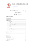
Switch mode power supply
NVM175 series
or
NVMx-abcde-f-g-h-i-jkl (may be prefixed by NS - # / where # may be
up to any four letters)
Unit Configuration Code where:
x = 1 for 175
a = Number of Outputs : 1 .
b = Channel 1 Output Voltage where: T is for 12V, F is for 15V and G
is for 24V
c,d,e = O (for omit) - non-safety related options.
f = Standby supply: 12Vdc (S,S1,S2,S3,C4 versions) 5Vdc (S5, S6)
g = U for U chassis, C for U chassis with cover, K for custom chassis
with cover and IEC inlet or blank for Open Frame.
h = Blank is the standard upright output connector, R is for the right
angle output connector.
i = Blank for standard leakage, L for low leakage.
jkl = Three numbers from 0 to 9 which denotes various output voltages
and currents within the specified range of channel 1 output for a
particular unit or blank for standard output setting.
Non standard models: X50001#, X50005# and X50007# (# can be any
letter not affecting safety)
Rating:
X50007# - NVM1D - double insulated model.
100-240Vac nom, 45-440Hz, 3A rms max.
(See Model Differences)
Applicant Name and Address:
TDK-LAMBDA UK LTD
KINGSLEY AVE
ILFRACOMBE
DEVON
EX34 8ES UNITED KINGDOM
Copyright © 2012
Created by UL Document Assembler 2012-03-26 06:22:41 -05:00
Issue Date:
2010-03-05
Page 2 of 15
Report Reference #
E135494-A59-UL
2012-03-21
This is to certify that representative samples of the products covered by this Test Report have been investigated in accordance with the
above referenced Standards. The products have been found to comply with the requirements covering the category and the products are
judged to be eligible for Follow-Up Service under the indicated Test Procedure. The manufacturer is authorized to use the UL Mark on
such products which comply with this Test Report and any other applicable requirements of UL LLC ('UL') in accordance with the FollowUp Service Agreement. Only those products which properly bear the UL Mark are considered as being covered by UL's Follow-Up
Service under the indicated Test Procedure.
The applicant is authorized to reproduce the referenced Test Report provided it is reproduced in its entirety.
UL authorizes the applicant to reproduce the latest pages of the referenced Test Report consisting of the first page of the Specific
Technical Criteria through to the end of the Conditions of Acceptability.
Any information and documentation involving UL Mark services are provided on behalf of UL LLC (UL) or any authorized licensee of UL.
Prepared by:
Chiang Shiau Hui
Reviewed by: Dennis Butcher
Copyright © 2012
Created by UL Document Assembler 2012-03-26 06:22:41 -05:00
Issue Date:
2010-03-05
Page 3 of 15
Report Reference #
E135494-A59-UL
2012-03-21
Supporting Documentation
The following documents located at the beginning of this Procedure supplement the requirements of this Test
Report:
A. Authorization - The Authorization page may include additional Factory Identification Code markings.
B. Generic Inspection Instructions i. Part AC details important information which may be applicable to products covered by this Procedure.
Products described in this Test Report must comply with any applicable items listed unless otherwise
stated in the body of this Test Report.
ii. Part AE details any requirements which may be applicable to all products covered by this Procedure.
Products described in this Test Report must comply with any applicable items listed unless otherwise
stated in the body of each Test Report.
iii. Part AF details the requirements for the UL Certification Mark which is not controlled by the technical
standard used to investigate these products. Products are permitted to bear only the Certification
Mark(s) corresponding to the countries for which it is certified, as indicated in each Test Report.
Product Description
The NVM-175 Series are switched mode power supplies for building into host equipment.
Both supply lines are fused. Appropriate cooling conditions must be fulfilled by the end-use product.
Storage temperature is -40 to 85°C (except NVM1D models as stated below)
No applied parts.
Marking label attached as Enclosure to this report is representative of all models.
Model Differences
Unit Configuration Code:
NVMx-abcde-f-g-h-i-jkl (may be prefixed by NS - # / where # may be up to any four letters)
where:
x = 1 for 175
a = Number of Outputs : 1 .
b = Channel 1 Output Voltage where: T is for 12V, F is for 15V and G is for 24V.
c = O (for omit).
d = O (for omit).
e = O (for omit).
f = Standby supply :
S for 12V version with power good, logic level high enables main output .
S1 for 12V version with power good, logic level low enables main output.
S2 for 12V version with Channel 1 good, logic level high enables main output.
S3 for 12V version with Channel 1 good, logic level low enables main output.
S4 for 12V 0.8A version with power good, logic level low enables main output.
S5 for 5V 0.5A version with power good, logic level low enables main output.
S6 for 5V 0.5A version with power good, logic level highenables main output.
g = U for U chassis, C for U chassis with cover, K for custom chassis with cover and IEC inlet or blank for
Open Frame.
h = Blank is the standard upright output connector, R is for the right angle output connector.
i = Blank for standard leakage, L for low leakage.
jkl = Three numbers from 0 to 9 which denotes various output voltages and currents within the specified
range of channel 1 output for a particular unit or blank for standard output setting
Output Parameters
Created by UL Document Assembler 2012-03-26 06:22:41 -05:00
Issue Date:
2010-03-05
Page 4 of 15
Report Reference #
E135494-A59-UL
2012-03-21
There are three NVM1 standard models with various options, and 3 non-standard models with output
parameters shown in the tables below:
Output Channel
Channel 1
Standby output
Voltage
Designation
T
F
G
S
S1
S2
S3
S4
S5
S6
Vout
Nom.
12
15
24
12
12
12
12
12
5
5
Adjustment
Range (V)
12 - 15.5
12 - 15.5
24 - 28.5
Fixed
Fixed
Fixed
Fixed
12 - 13
Fixed
Fixed
Output
Maximum
Current (A)
Power (W)
15
180
15
180
7.5
180
0.2
2.4
0.2
2.4
0.2
2.4
0.2
2.4
0.8
10.4
0.5
2.5
0.5
2.5
Variations and limitations of use:
NVM175 PSUs can output 180W from channel 1 plus 10.4W maximum from the standby output.
Component temperatures must be monitored in the end use application as described in the “COOLING FOR
UNIT” section.
All ratings apply for ambient temperatures up to 50°C. From 50 to 70°C the total output power and current
ratings are both derated at 2.5% per deg C.
Non-Standard Model:
Non- Standard model: X50001# (# can be any letter), (modified NVM1-1T000-S1-K-R-L)
Voltage
Vout
Adjustment
Output
Maximum
Output Channel
Designation Nom.
Range (V)
Current (A)
Power(W)
Channel 1
T
12
12 - 15.5
15
180
Standby output
S1
12
Fixed
0.2
2.4
Additional Variations and limitations of use for Non- Standard model X50001#:
Ratings apply for ambient temperatures up to 60°C. From 60 to 65°C the total output power and current
ratings are both derated at 2.5% per deg C.
Component temperatures must be monitored in the end use application as described in the “COOLING FOR
UNIT” section.
X50005# - (# can be any letter), (modified NVM1-1T model) with 5V 0.5A standby option.
X50007# - NVM1D - 1G-f-g-h-j
# may be any letter where this indicates any of the options described in the nomenclature table above for f, g,
h and j and where g will always be blank (open frame). D indicates that the product is double insulated (no
earth connections). This product has 18-way output connector.
Maximum storage temperature 65°C.
For ambient temperature requirements see Conditions of Acceptability and user manual (Enclosure 6-01).
Technical Considerations
Created by UL Document Assembler 2012-03-26 06:22:41 -05:00
Issue Date:
2010-03-05
Page 5 of 15
Report Reference #
E135494-A59-UL
2012-03-21
Equipment mobility : for building-in
Connection to the mains : Connection to mains to be determined in end use.
Operating condition : continuous
Access location : for building-in
Over voltage category (OVC) : OVC II
Mains supply tolerance (%) or absolute mains supply values : +10%, -10%
Tested for IT power systems : Yes (Norway only)
IT testing, phase-phase voltage (V) : 230V
Class of equipment : Class I (earthed)
Considered current rating (A) : 20A
Pollution degree (PD) : PD 2
IP protection class : IP X0
Altitude of operation (m) : 5000m
Altitude of test laboratory (m) : 64m
Mass of equipment (kg) : Less than 1 kg
The product was submitted and evaluated for use at the maximum ambient temperature (Tma)
permitted by the manufacturer’s specification of: 50°C (full load); 70°C (power and output current
decreasing linearly by 2.5%/°C above 50°C). Model X50001x, 60°C (full load); 65°C (power and
output current decreasing linearly by 2.5%/°C above 60°C), NVM1D max temp 65°C.
The means of connection to the mains supply is: To be determined in the end-use product
The product is intended for use on the following power systems: IT (Norway only), TN
The equipment disconnect device is considered to be: provided by the end equipment
The product was investigated to the following additional standards: EN 60950-1:2006+ A11:2009
Created by UL Document Assembler 2012-03-26 06:22:41 -05:00
Issue Date:
2010-03-05
Page 6 of 15
Report Reference #
E135494-A59-UL
2012-03-21
(which includes all European national differences, including those specified in this test report).
The following were investigated as part of the protective earthing/bonding: Printed wiring board trace
(refer to Enclosure - Schematics + PWB for layouts)
The following are available from the Applicant upon request: Installation (Safety) Instructions /
Manual
Maximum altitude of operation is 5000m for all models. The requirements of IEC60664-1 table A.2
were applied for calculating the required clearances.
Engineering Conditions of Acceptability
For use only in or with complete equipment where the acceptability of the combination is determined by UL
LLC. When installed in an end-product, consideration must be given to the following:
The following Production-Line tests are conducted for this product: Electric Strength, Earthing
Continuity (except NVM1D model)
The end-product Electric Strength Test is to be based upon a maximum working voltage of: PrimarySELV: 410 Vrms, 697 Vpk, Primary-Earthed Dead Metal: 398 Vrms, 662 Vpk
The following secondary output circuits are SELV: All
The following secondary output circuits are at non-hazardous energy levels: All
The following output terminals were referenced to earth during performance testing: All outputs and
their return lines individually referenced to earth to obtain maximum working voltage.
The power supply terminals and/or connectors are: Suitable for factory wiring only
The maximum investigated branch circuit rating is: 20 A
The investigated Pollution Degree is: 2
Proper bonding to the end-product main protective earthing termination is: Required (except for
NVM1D model)
An investigation of the protective bonding terminals has: Been conducted
The following magnetic devices (e.g. transformers or inductor) are provided with an OBJY2 insulation
system with the indicated rating greater than Class A (105°C): Transformer T1, T2 and T3 (Class F) See table 1.5.1 for details of insulation systems used
Created by UL Document Assembler 2012-03-26 06:22:41 -05:00
Issue Date:
2010-03-05
Page 7 of 15
Report Reference #
E135494-A59-UL
2012-03-21
The following end-product enclosures are required: Mechanical, Fire, Electrical
The following components require special consideration during end-product Thermal (Heating) tests
due to the indicated maximum temperature measurements during component-level testing: Refer to
enclosure Manuals ID 6-01 Cooling for units table.
Additional Information
N/A
Additional Standards
The product fulfills the requirements of: CSA C22.2 No. 60950-23-07, EN 60950-1:2006 + A11:2009, UL
60950-1 2nd Ed. Revised 2007-03-27
Markings and instructions
Clause Title
Power rating - Company
identification
Power rating -
Marking or Instruction Details
Listee's or Recognized company's name, Trade Name, Trademark or File
Number
Model Number
Model
Power rating Ratings
Fuses - Non-operator
access/soldered-in
fuses
Warning to service
personnel
Ratings (voltage, frequency/dc, current)
Unambiguous reference to service documentation for instructions for
replacement of fuses replaceable only by service personnel
"CAUTION: Double pole/neutral fusing"
Special Instructions to UL Representative
N/A
Created by UL Document Assembler 2012-03-26 06:22:41 -05:00
Issue Date:
2010-03-05
Page 8 of 15
Report Reference #
E135494-A59-UL
2012-03-21
Production-Line Testing Requirements
Electric Strength Test Special Constructions - Refer to Generic Inspection Instructions, Part AC for
further information.
Model
Component
Removable
Parts
Test probe location
V
rms
V dc
Test Time,
s
N/A
Earthing Continuity Test Exemptions - This test is not required for the following models:
Electric Strength Test Exemptions - This test is not required for the following models:
Electric Strength Test Component Exemptions - The following solid-state components may be
disconnected from the remainder of the circuitry during the performance of this test:
Sample and Test Specifics for Follow-Up Tests at UL
Model
Component
Material
N/A
Created by UL Document Assembler 2012-03-26 06:22:41 -05:00
Test
Sample(s)
Test
Specifics