1
SERIES 60 SERVICE MANUAL
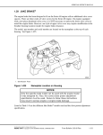
The two special bolts locate the cap relative to the upper end. The assembly is machined as a unit
and must not be used in the engine with any other cap or upper end. Orientation of the cap to the
upper end is identified by stamped numbers.
NOTE:
The Series 60G engine connecting rod is shorter in length and identified by "Natural
Gas" on the side.
The current connecting rods with smaller rod chamfers replaced the former connecting rods,
effective with the following engine serial numbers: (listed in Table 1-7.)
Table 1-7
Engine Model
Engine Serial Number
6067WK60 (11.1L)
6R184522
6067GK60 (12.7L)
6R188251
New Connecting Rod Replacements
This change was made to allow installation of new, wider connecting rod bearings that provide
improved oil film thickness and reduced bearing pressures.
The rod chamfers on the current connecting rods are smaller than those on the former rods. This
has been done to provide proper support for the wider bearings. To conform with this change,
new crankshafts with smaller fillet radii have been released. Refer to section 1.7 for information
on the new crankshafts.
NOTE:
The current connecting rods, bearings, and crankshafts must be used together to ensure
interchangeability. Former parts cannot be mixed with new parts in the same engine.
The former connecting rods will continue to be available for engines built prior to the
unit serial numbers as listed in Table 1-7.
The connecting rod bearing shells are precision made and are of the replaceable type. The upper
bearing shell is seated in the connecting rod and a lower bearing shell is seated in the connecting
rod cap. These bearings are not identical. The upper and lower bearing shells are located in the
connecting rod by a tang at the parting line at one end of each bearing shell. See Figure 1-299.
The tri-metal bearing wear surfaces use a steel backing. First, an optimum composition (copper,
tin and lead) lining is bonded to the steel back. A nickel barrier above the lining and the overlay
serves to prevent tin migration. A soft lead overlay, 0.025 mm (0.001 in.) thick, provides run-in
protection, and an initial wear surface. A flash tin plate, front and back, is for added corrosion
protection and resistance during shipping and handling. These bearings are identified by the satin
silver sheen of the tin when new, and a dull gray of the overlay after being in service.
All information subject to change without notice.
(Rev. 01/04)
6SE483 0303 Copyright © 2003 DETROIT DIESEL CORPORATION
From Bulletin 20-60-03Rev.
1-365