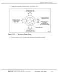
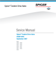
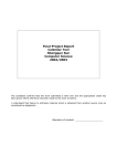
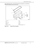
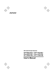
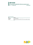
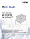
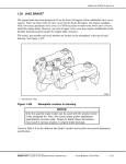
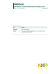
1
SERIES 60 SERVICE MANUAL
Install the fire and compression rings as follows:
NOTICE:
To avoid breaking or overstressing the rings, do not spread them
any more than necessary to slip them over the piston dome.
1. Starting with the compression ring (second groove), install the compression ring and fire
ring with tool J 8128. See Figure 1-274k. Make sure the identifying dimple on the rings
is installed up, toward the dome of the piston. See Figure 1-274d for ring identification
and locations.
2. Stagger the ring gaps around the piston. see Figure 1-274k.
Figure 1-274k
Forged Steel Piston Ring Positioning (Diesel)
3. Refer to section 1.18.4 for piston and connecting rod assembly procedure.
All information subject to change without notice.
(Rev. 01/04)
6SE483 0303 Copyright © 2003 DETROIT DIESEL CORPORATION
From Bulletin 19-60-03Rev.
1-336m
1.18
PISTON AND CONNECTING ROD ASSEMBLY
1.18 PISTON AND CONNECTING ROD ASSEMBLY
Since the piston and connecting rod assembly is one unit made of two separate components, the
components will be addressed in separate sections.
For general piston information, refer to section 1.17.
For general connecting rod assembly information, refer to section 1.19. The 14L and 12.7L
On-Highway engines built after December 1, 2003 requires that the piston, connecting rod,
and cylinder liner be removed as an assembly.
NOTE:
Some 14L and steel cylinder kit procedures differ from the cast iron procedures.
Information regarding 14L and steel cylinder kits will follow cast iron procedures when
different.
(Rev. 01/04)
1-336n
From Bulletin 19-60-03Rev.
All information subject to change without notice.
6SE483 0303 Copyright © 2003 DETROIT DIESEL CORPORATION
SERIES 60 SERVICE MANUAL
1.18.1
Repair or Replacement of Piston and Connecting Rod
To determine if repair is possible or replacement is necessary, perform the following procedure.
See Figure 1-275.
Figure 1-275
Flowchart for Repair or Replacement of Piston and Connecting
Rod
All information subject to change without notice.
(Rev. 01/04)
6SE483 0303 Copyright © 2003 DETROIT DIESEL CORPORATION
From Bulletin 19-60-03Rev.
1-337
1.18
PISTON AND CONNECTING ROD ASSEMBLY
1.18.2
Removal and Cleaning of Piston and Connecting Rod
Precleaning is not necessary.
Remove the piston and connecting rod assembly as follows (except 14L and 12.7 EGR
On-Highway engines):
1. Drain the engine cooling system. Refer to section 13.13.4.
2. Drain the engine oil. Refer to section 13.13.1.
3. Remove the oil pan. Refer to section 3.11.2.
4. For pre-1991 engines, disconnect and remove the lubricating oil pump inlet pipe and
screen assembly, oil pump outlet pipe and lubricating oil pump. Refer to section 3.2.2.
See Figure 1-276.
NOTE:
It is not necessary to remove the oil pump on 1991 and later model year engines.
Figure 1-276
Oil Pump Removal (Pre-1991 Engines)
(Rev. 01/04)
1-338
From Bulletin 19-60-03Rev.
All information subject to change without notice.
6SE483 0303 Copyright © 2003 DETROIT DIESEL CORPORATION
SERIES 60 SERVICE MANUAL
5. Remove the cylinder head. Refer to section 1.2.2.
6. Use an emery cloth to remove any carbon deposits from the upper surface of the cylinder
liner.
NOTICE:
If installed, remove the piston cooling nozzles from the base
of the cylinder bores to prevent nozzle damage, during piston
removal.
7. Remove the bearing cap and lower bearing shell from the connecting rod.
8. Install connecting rod guides, J 35945 (or equivalent) for removing cast iron pistons or
J 43661(or equivalent) for removing forged steel pistons, to protect the crankshaft journals.
9. Push the piston and rod assembly out through the top of the cylinder block.
NOTE:
The piston cannot be removed from the bottom of the cylinder block.
All information subject to change without notice.
(Rev. 01/04)
6SE483 0303 Copyright © 2003 DETROIT DIESEL CORPORATION
From Bulletin 19-60-03Rev.
1-339
1.18
PISTON AND CONNECTING ROD ASSEMBLY
10. Assemble the bearing cap and lower bearing shell to the connecting rod after removal.
If not already marked, match-mark the rod and cap (on the tang side) with the cylinder
number from where they were removed. See Figure 1-277.
Figure 1-277
Connecting Rod and Cap Identification
NOTE:
When removed, the bearing cap and the bearing shell must be reinstalled on the original
connecting rod before another connecting rod bearing cap is removed.
NOTE:
If removing the piston and connecting rod assembly to work on the cylinder liner, stop
here. Refer to section 1.20.2 for cylinder liner removal procedure.
(Rev. 01/04)
1-340
From Bulletin 19-60-03Rev.
All information subject to change without notice.
6SE483 0303 Copyright © 2003 DETROIT DIESEL CORPORATION
SERIES 60 SERVICE MANUAL
Remove the 14L and 12.7L EGR On-Highway cylinder liner, piston and connecting rod
assembly as follows::
1. Drain the engine cooling system. Refer to section 13.13.4.
2. Drain the engine oil. Refer to section 13.13.1.
3. Remove the oil pan. Refer to section 3.11.2.
4. Remove the cylinder head. Refer to section 1.2.2.
5. Position the crankshaft journal for the cylinder kit assembly to be removed at bottom
dead center.
6. Remove the bearing cap.
7. Insert cylinder kit removal tool J 45876 in the bore of the cylinder to be removed. Tighten
the bolt snug. (Do not overtighten.). See Figure 1-278.
Figure 1-278
Cylinder Kit Removal Tool J 45876
8. Install the oil nozzle protectors, J 34317. Close the air valve in the removal tool.
9. Rotate the engine by hand until the entire cylinder kit assembly is pushed up where the
liner can be removed by grabbing the tool to pull the kit completely out of the engine block.
All information subject to change without notice.
(Rev. 01/04)
6SE483 0303 Copyright © 2003 DETROIT DIESEL CORPORATION
From Bulletin 19-60-03Rev.
1-341
1.18
PISTON AND CONNECTING ROD ASSEMBLY
10. Assemble the bearing cap and lower bearing shell to the connecting rod after removal.
If not already marked, match-mark the rod and cap (on the tang side) with the cylinder
number from where they were removed. See Figure 1-279.
Figure 1-279
Connecting Rod and Cap Identification
NOTE:
When removed, the bearing cap and the bearing shell must be reinstalled on the original
connecting rod before another connecting rod bearing cap is removed.
11. Withdraw the piston and rod assembly through the bottom of the cylinder liner.
NOTE:
The rod will not fit through the inside diameter of the cylinder liner.
(Rev. 01/04)
1-342
From Bulletin 19-60-03Rev.
All information subject to change without notice.
6SE483 0303 Copyright © 2003 DETROIT DIESEL CORPORATION
SERIES 60 SERVICE MANUAL
1.18.3
Disassembly of Piston and Connecting Rod Assembly
Piston assembly components should be segregated by cylinder and match-marked during
disassembly to ensure they are assembled in the same position and orientation.
NOTICE:
Stamping cylinder numbers on the piston assembly will damage
the components.
It is best to use a paint pencil. For cast iron pistons, mark the pin, skirt, bushing, and dome ear
at the front. For forged steel pistons, mark the pin, skirt, and dome. For forged steel piston
assemblies mark the pin and the dome/skirt assembly.
If the second ring on the cast iron piston is a rectangular section, the engine should be fitted with
the current cast iron piston assemblies that contain a Second Keystone Ring (SKR) configuration.
Former piston rings must NOT be used in the SKR configuration.
Disassemble the cast iron piston and connecting rod assembly as follows:
1. Place the piston, dome down, on the round plate of the piston and connecting rod holding
fixture, J 36211. See Figure 1-280.
Figure 1-280
Piston Connecting Rod Holding Fixture
2. Slide the movable portion of the fixture until it contacts the piston pin and tighten the
handle.
All information subject to change without notice.
(Rev. 01/04)
6SE483 0303 Copyright © 2003 DETROIT DIESEL CORPORATION
From Bulletin 19-60-03Rev.
1-343
1.18
PISTON AND CONNECTING ROD ASSEMBLY
3. Loosen the two bolts that secure the connecting rod to the piston pin and remove the two
bolts and spacers.
4. Remove the connecting rod.
5. Remove the piston, pin and skirt from the holding fixture.
Disassemble the 12.7L and 14L forged steel piston and connecting rod assembly as follows:
1. Place the piston, dome down, on the table. See Figure 1-281.
Figure 1-281
Positioning of the Piston and Connecting Rod Assembly
2. Using the required snap ring pliers, remove the circlip-type snap rings from the piston skirt.
NOTE:
For forged steel one piece piston assemblies skip to step 5.
3. Slide out the piston pin and remove the rod from the piston.
4. Disassemble the piston dome from the skirt.
5. Slide out the piston pin and remove the connecting rod from piston assembly.
(Rev. 01/04)
1-344
From Bulletin 19-60-03Rev.
All information subject to change without notice.
6SE483 0303 Copyright © 2003 DETROIT DIESEL CORPORATION
SERIES 60 SERVICE MANUAL
1.18.3.1
Inspection of Piston and Connecting Rod Assembly
Refer to section 1.17.3 for disassembly of the piston and piston ring.
Refer to section 1.17.3.1 for inspection of the piston and piston ring.
Refer to section 1.19.3 for disassembly of the connecting rod.
Refer to section 1.19.3.1 for inspection of the connecting rod.
NOTE:
Steel dome piston pin bearings and bushingless pin bores are not serviced. If they are
found damaged then the replacement of the dome is required. The same is true for the
rod bearings. If they are found damaged then the replacement of the rod is required as
well.
1.18.4
Assembly of Piston and Connecting Rod Assembly
Assemble the cast iron piston and connecting rod assembly as follows:
NOTICE:
The connecting rod-to-piston pin attaching bolts and spacers are
specially designed components. No other bolts or spacers may
be used. Piston pin bolts are considered one-use items and
must be replaced with new bolts when removed for any reason.
Failure to observe this precaution may result in bolt loosening
or breaking during engine operation, which may cause serious
engine damage.
1. Discard used piston pin bolts and replace with new bolts.
2. Because of the low clearance fit between the piston pin and three-piece pin bearing, care
in handling and cleanliness of piston dome bore, bearings, and piston pin are important.
Otherwise, assembly may be impossible. The specifications on reusing piston assembly
components are listed in Table 1-17 and listed in Table 1-20.
3. The pin bore and bearing backs should be wiped clean prior to installation of the bushings
in the piston dome.
4. Installing piston pin bearings (with the piston dome standing on the rim) requires the
upper bearing piece to be inserted through the end of the pin bore and dropped over
the retaining pin.
5. The lower bearing pieces are inserted flat side in by tilting the bearing at approximately a
30 degree angle from the vertical away from the dome ear.
6. Set the edge of the bearing parting line on the edge of the upper piece notch and rotate the
lower bushing up and into place. The lower bearing can then be pushed full into the bore.
7. Lubricate the piston pin bearings with clean engine oil. (Straight 30 weight oil is
recommended.)
All information subject to change without notice.
(Rev. 01/04)
6SE483 0303 Copyright © 2003 DETROIT DIESEL CORPORATION
From Bulletin 19-60-03Rev.
1-345
1.18
PISTON AND CONNECTING ROD ASSEMBLY
8. Set the piston skirt on the piston dome.
9. Align the piston pin holes in the dome and skirt.
10. Check the piston pin for foreign matter in the bolt holes.
11. Lubricate the pin with clean engine oil and install in the bores with the bolt holes facing
the connecting rod, away from the dome.
NOTE:
The piston pin may feel considerably tighter than with conventional designs and possibly
may not be turned easily by hand. Proper pin and bearing installation should result in a
piston assembly in which the pin can be turned with the connecting rod while the piston
dome is standing on the rim and the piston skirt is held with the other hand.
12. Apply a small amount of International Compound #2®, or equivalent, to the bolt threads
and bolt head contact surfaces and both ends of the spacers.
NOTICE:
The connecting rod-to-piston pin attaching bolts and spacers are
specially designed components. No other bolts or spacers may
be used. Piston pin bolts are considered one-time use items and
must be replaced with new bolts when removed for any reason.
Failure to observe this precaution may result in bolt loosening
or breakage during engine operation, which may cause serious
engine damage.
13. Install the spacers on the two special connecting rod-to-piston attaching bolts.
14. After clamping the connecting rod in holding fixture, J 36211, torque each piston pin bolt
to 95-122 N·m (70-90 lb·ft). See Figure 1-280.
15. Complete the process by tightening the bolts to 150.2–163.8 N·m (110–120 lb·ft) final
torque.
(Rev. 01/04)
1-346
From Bulletin 19-60-03Rev.
All information subject to change without notice.
6SE483 0303 Copyright © 2003 DETROIT DIESEL CORPORATION
SERIES 60 SERVICE MANUAL
Assemble the steel piston and connecting rod assembly as follows:
1. Position the piston dome on it’s rim. See Figure 1-282.
Figure 1-282
Positioning of Piston Dome
NOTE:
If piston is a one piece forged steel piston assembly proceed to step 5.
2. Set the piston skirt on the piston dome.
3. Place the piston skirt on the piston dome with the notches facing away from the dome.
4. Align the piston pin bores of the dome and skirt.
5. Liberally lubricate the piston pin bearings or brushingless pin bore in the dome and
connecting rod bearing with clean engine oil.
6. Using the required snap ring pliers, install one of the circlip-type snap rings into the recess
in the piston skirt. Orient the snap ring gap to either the 12 o’clock or 6 o’clock position.
7. Lubricate the pin with clean engine oil.
8. Position the end of the connecting rod inside the piston dome.
All information subject to change without notice.
(Rev. 01/04)
6SE483 0303 Copyright © 2003 DETROIT DIESEL CORPORATION
From Bulletin 19-60-03Rev.
1-347
1.18
PISTON AND CONNECTING ROD ASSEMBLY
NOTICE:
Do not mix piston pins in an engine. Failure to install the same
piston pins in an engine may result in an unbalance condition
indicated by severe vibration. Excessive vibration will have a
detrimental effect on engine life. To avoid this situation, always
check the part number on the end of the existing piston pin or
measure the piston pin I.D. before installing the new pin.
9. Piston pins must not be mixed in an engine. Install piston pin into the pin bores through
rod until it rests against the previously installed snap ring.
10. Using the required snap ring pliers, install the other circlip-type snap ring into the recess
in the piston skirt to lock the pin in place. Orient the snap ring gap to either the 12 o’clock
or 6 o’clock position.
(Rev. 01/04)
1-348
From Bulletin 19-60-03Rev.
All information subject to change without notice.
6SE483 0303 Copyright © 2003 DETROIT DIESEL CORPORATION
SERIES 60 SERVICE MANUAL
1.18.5
Installation of Piston and Connecting Rod Assembly
To install the piston and connecting rod assembly to the engine (except 14L and 12.7 L), perform
the following:
1. If the rings have been removed, install them onto the dome, refer to section . If the piston
rings are installed, proceed to step 2.
2. Add clean engine oil to a clean pan at least 305 mm (12 in.) in diameter, until the level
reaches approximately 76 mm (3 in.).
3. Place the piston and connecting rod assembly into pan, with the dome of the piston on
the bottom of the pan. See Figure 1-283.
4. Coat the piston liberally with the engine oil, saturating the piston rings and lands.
Figure 1-283
Piston and Connecting Rod Assembly Lubrication
All information subject to change without notice.
(Rev. 01/04)
6SE483 0303 Copyright © 2003 DETROIT DIESEL CORPORATION
From Bulletin 19-60-03Rev.
1-349
1.18
PISTON AND CONNECTING ROD ASSEMBLY
5. Position (stagger) the piston ring gaps properly on the piston at 90 degree intervals.
See Figure 1-284 for diesel engines and see Figure 1-285 for natural gas engines.
Figure 1-284
Piston Ring Positioning (Diesel)
Figure 1-285
Piston Ring Positioning (Natural Gas)
(Rev. 01/04)
1-350
From Bulletin 19-60-03Rev.
All information subject to change without notice.
6SE483 0303 Copyright © 2003 DETROIT DIESEL CORPORATION
SERIES 60 SERVICE MANUAL
6. Place the piston, dome down, in the bottom of the pan. Center the dome of the piston
within the pan.
7. Coat the inside diameter of the ring compression tool, J 35598–A, liberally with clean
engine oil from the pan.
NOTICE:
Inspect the piston ring compressor for nicks or burrs, especially
at the non-tapered inside diameter end. Nicks or burrs on the
inside diameter of the ring compressor may result in damage to
the piston rings.
8. Install the tapered end of the piston ring compression tool over the end of the connecting
rod, and down onto the piston. As the compression tool slides down the piston to the
piston ring area, apply slow, even pressure on both sides of the compression tool to
compress the rings. See Figure 1-286.
Figure 1-286
Installing Piston and Connecting Rod Assembly into Ring
Compressor
9. Slide the compression tool down until it contacts the bottom of the drain pan.
10. Position the crankshaft so that the connecting rod journal for the cylinder being worked on
is at bottom-dead-center.
11. Remove the cap from the connecting rod.
All information subject to change without notice.
(Rev. 01/04)
6SE483 0303 Copyright © 2003 DETROIT DIESEL CORPORATION
From Bulletin 19-60-03Rev.
1-351
1.18
PISTON AND CONNECTING ROD ASSEMBLY
NOTICE:
Do not allow the connecting rod to contact the cylinder liner on
installation, or damage to the liner may occur. The numbers
on the side of the connecting rod and cap identify the rod with
the cap and indicate the particular cylinder in which they are
used. If a new service connecting rod is to be installed, the same
identification numbers must be stamped in the same location (on
the tang side of the rod and cap) as on the connecting rod that
was replaced.
12. Install connecting rod guide, (J 35945 for cast iron piston or J 43661 for forged steel
piston) over the ends of the connecting rod bolts to prevent damaging the crankshaft
journals or the joint face of the rod. The guides also prevent the connecting rod from
contacting the liner and damaging the surface. See Figure 1-287.
Figure 1-287
Connecting Rod Guides Installation
NOTE:
The connecting rod guides are threaded at the upper end and attach to the rod bolts.
(Rev. 01/04)
1-352
From Bulletin 19-60-03Rev.
All information subject to change without notice.
6SE483 0303 Copyright © 2003 DETROIT DIESEL CORPORATION
SERIES 60 SERVICE MANUAL
NOTICE:
Do not lift the assembly using the connecting rod guides. The
assembly could dislodge from the connecting rod guides and
could cause engine damage.
13. Grasp the connecting rod assembly with one hand, and the piston ring compressor with the
other. Lift the assembly out of the pan, and allow excess oil to drain back into the pan.
NOTE:
Do not allow the piston to slide out of the bottom of the ring compressor.
14. With the crankshaft throw in the bottom position, ensure the number on the connecting
rod is towards the cooler side of the engine, place the ring compressor and the piston and
connecting rod assembly over the cylinder where it is to be installed. See Figure 1-288.
Figure 1-288
Connecting Rod Indexing
NOTE:
There are orientation lugs cast into one side of the upper and lower sections of the
connecting rod. These orientation lugs face the front of the engine. See Figure 1-289.
All information subject to change without notice.
(Rev. 01/04)
6SE483 0303 Copyright © 2003 DETROIT DIESEL CORPORATION
From Bulletin 19-60-03Rev.
1-353
1.18
PISTON AND CONNECTING ROD ASSEMBLY
Figure 1-289
Orientation Lugs
(Rev. 01/04)
1-354
From Bulletin 19-60-03Rev.
All information subject to change without notice.
6SE483 0303 Copyright © 2003 DETROIT DIESEL CORPORATION
SERIES 60 SERVICE MANUAL
NOTICE:
When installing a forged steel piston into the engine, care must
be taken to avoid damaging the piston cooling nozzle installed
at the base of the cylinder bore. Before loading the piston into
the liner, turn the connecting rod so that the bearing end is offset
approximately 10–15 degrees and not perpendicular to the
crankshaft, as is the case with cast iron pistons. This will ensure
that the rod end does not strike the nozzle when the piston is
pushed in. Once the rod end is past the nozzle, turn the rod so
that the bearing end is perpendicular to the crankshaft journal.
NOTICE:
Failure to orient the piston connecting rod properly during forged
steel piston installation may result in the bearing end of the rod
striking the nozzle, causing damage to the nozzle or loosening
it from the block. A damaged, bent, or loosened nozzle may
cause a loss of main gallery oil pressure. In these cases, piston
overheating or lack of adequate lubrication may result in severe
engine damage.
15. Position the ring compressor, with piston and connecting rod inside, into the
proper cylinder until the ring compressor is resting squarely on the cylinder liner.
See Figure 1-290.
Figure 1-290
Use of Ring Compressor
All information subject to change without notice.
(Rev. 01/04)
6SE483 0303 Copyright © 2003 DETROIT DIESEL CORPORATION
From Bulletin 19-60-03Rev.
1-355
1.18
PISTON AND CONNECTING ROD ASSEMBLY
NOTICE:
Do NOT force the piston into the liner. The oil ring expander
applies considerable force on the oil ring. Therefore, care must
be taken during the loading operation to prevent ring breakage.
16. Push the piston and connecting rod assembly down into the liner until the piston is free
of the ring compressor.
17. Remove the piston ring compressor.
18. Push or tap the piston and connecting rod assembly into the liner, turning the rod, if
necessary, until the upper bearing shell is firmly seated on the appropriate crankshaft
journal.
19. Remove the connecting rod guide from the ends of the connecting rod bolts.
NOTE:
Be sure the connecting rod bolts have not been unseated or turned and the bearing
locating tang is in its proper location.
20. Place the lower bearing shell in the connecting rod cap, indexing the tang on the bearing
with the notch in the cap.
21. Lubricate the bearing shell with clean engine oil.
22. Install the bearing cap. The number on the cap and rod should be on the same (oil cooler)
side. See Figure 1-291.
Figure 1-291
Connecting Rod and Cap Identification
(Rev. 01/04)
1-356
From Bulletin 19-60-03Rev.
All information subject to change without notice.
6SE483 0303 Copyright © 2003 DETROIT DIESEL CORPORATION
SERIES 60 SERVICE MANUAL
23. Torque the connecting rod bolts alternately to 160-185 N·m (118-137 lb·ft).
24. Check connecting rod side clearance by moving the rod from crank cheek to crank cheek.
If there is no clearance, check for proper bearing cap installation.
25. Install the remaining piston and rod assemblies in the same manner.
26. Install a new head gasket. Refer to section 1.2.5.
27. Install the cylinder head. Refer to section 1.2.5.
28. If previously removed, install the piston cooling nozzles at the base of the cylinder bores.
29. Install the lubricating oil pump inlet pipe and screen assembly, and the lubricating oil
pump. Refer to section 3.2.6.
30. Install the oil pan. Refer to section 3.11.4.
31. Complete any other engine assembly as necessary.
32. After the engine has been completely assembled, refill the crankcase to the proper level
on the dipstick. Refer to section 13.13.1.
33. Close the drain cocks and fill the engine with the recommended coolant. Refer to section 13.13.4,
for refilling procedure and refer to section 5.4.
NOTE:
Coolant system maintenance is very important. Bleed off all the air from the system
and top off.
34. Perform the following steps for verifying repairs made to the piston and connecting
rod assembly:
[a]
If new parts such as pistons, rings, cylinder liners or bearings were installed, operate
the engine on the run-in schedule. Refer to section 11.8.3.2.
[b]
If used parts such as pistons, rings, cylinder liners or bearings were installed,
refer to section 11.3 for verification of proper piston and connecting rod assembly
installation.
Install the 14L and 12.7 EGR On-Highway liner, piston and connecting rod assembly as
follows:
1. If the rings have been removed, install them onto the dome, refer to section 1.17.4. If the
piston rings are installed, proceed to step 2.
2. Add clean engine oil to a clean pan at least 305 mm (12 in.) in diameter, until the level
reaches approximately 76 mm (3 in.).
3. Place the piston and connecting rod assembly into pan, with the dome of the piston on
the bottom of the pan. See Figure 1-292.
All information subject to change without notice.
(Rev. 01/04)
6SE483 0303 Copyright © 2003 DETROIT DIESEL CORPORATION
From Bulletin 19-60-03Rev.
1-357
1.18
PISTON AND CONNECTING ROD ASSEMBLY
4. Coat the piston liberally with the engine oil, saturating the piston rings and lands.
Figure 1-292
Piston and Connecting Rod Assembly Lubrication
5. Remove assembly from pan and position (stagger) the piston ring gaps properly on the
piston at 90 degree intervals. See Figure 1-293 for diesel engines.
Figure 1-293
Piston Ring Positioning (Diesel)
(Rev. 01/04)
1-358
From Bulletin 19-60-03Rev.
All information subject to change without notice.
6SE483 0303 Copyright © 2003 DETROIT DIESEL CORPORATION
SERIES 60 SERVICE MANUAL
6. Place the piston, dome down, in the bottom of the pan. Center the dome of the piston
within the pan.
7. Coat the inside diameter of the ring compression tool, J 43397 liberally with clean
engine oil from the pan. For 12.7L and 14L On-Highway forged steel piston assemblies
procede to step 8.
8. For 12.7L and 14L On-Highway piston assemblies only, coat the inside diameter of the
ring compression tool J 46927 for 12.7L engines and J 46929 for 14L engines.
9. Clamp the ring compressor, with groove (pilot bore) of the compressor facing away from
the connecting rod, around the dome and rings.
10. Once the compressor is "clamped," ensure the piston can rotate freely. If rotation is
hindered, remove the compressor and reposition the dome and rings, or inspect for ring
damage.
11. Lubricate and install cylinder liner seals.
12. Lubricate the inside of the cylinder liner.
13. Position the liner so it rests on its flange.
All information subject to change without notice.
(Rev. 01/04)
6SE483 0303 Copyright © 2003 DETROIT DIESEL CORPORATION
From Bulletin 19-60-03Rev.
1-359
1.18
PISTON AND CONNECTING ROD ASSEMBLY
14. Position the ring compressor clamped around the dome and rod assembly so the groove
rests on the bottom of the cylinder liner. See Figure 1-294 and see Figure 1-294a.
Figure 1-294
Installation of Ring Compressor
Figure 1-294a
Installation of Ring Compressor for One piece Forged Steel
Piston Assembly
(Rev. 01/04)
1-360
From Bulletin 19-60-03Rev.
All information subject to change without notice.
6SE483 0303 Copyright © 2003 DETROIT DIESEL CORPORATION
SERIES 60 SERVICE MANUAL
NOTICE:
Do NOT force the dome into the liner. Considerable force on
the dome could scratch or otherwise damage the inside of
the cylinder liner. Therefore, care must be taken during the
installation of the dome to prevent damage.
15. With care and moderate pressure, press the dome into the liner until the dome is
approximately half way into the liner. See Figure 1-295.
1. Cylinder
Figure 1-295
2. Piston Rod
Installation of Piston and Rod Assembly
16. Remove the ring compressor.
17. Remove the cap from the connecting rod.
18. Install oil nozzle protectors, J 43661.
19. Position the throw of the crankshaft journal to bottom dead center for the cylinder being
installed with the liner, piston and connecting rod assembly.
All information subject to change without notice.
(Rev. 01/04)
6SE483 0303 Copyright © 2003 DETROIT DIESEL CORPORATION
From Bulletin 19-60-03Rev.
1-361
1.18
PISTON AND CONNECTING ROD ASSEMBLY
NOTICE:
When installing a forged steel piston into the engine, care must
be taken to avoid damaging the piston-cooling nozzle installed
at the base of the cylinder bore. Before loading the piston/rod
liner assembly into the block, turn the connecting rod so that
the bearing end is offset approximately 10-15 degrees and not
perpendicular to the crankshaft, as is the case with cast iron
pistons. This will ensure that the rod end does not strike the
nozzle when the piston is pushed in the cylinder liner. Once the
rod end is past the nozzle, turn the rod so that the bearing end
is perpendicular to the crankshaft journal.
Notice
Failure to orient the piston connecting rod properly during forged
steel piston installation may result in the bearing end of the rod
striking the nozzle, causing damage to the nozzle or loosening
it from the block. A damaged, bent, or loosened nozzle may
cause a loss of main gallery pressure. In these cases piston
overheating or lack of adequate lubrication may result in severe
engine damage.
20. For steel forged one piece piston assemblies, ensure arrow on piston dome is pointing
toward the front of the engine during installation. See Figure 1-295a.
Figure 1-295a
Piston Dome Steel Forged One Piece Piston Assembly
(Rev. 01/04)
1-362
From Bulletin 19-60-03Rev.
All information subject to change without notice.
6SE483 0303 Copyright © 2003 DETROIT DIESEL CORPORATION
SERIES 60 SERVICE MANUAL
21. Slide the cylinder kit assembly into the cylinder block noting the position of the connecting
rod to ensure the rod is assembled to the same position as it was when removed. Push by
hand until resistance is felt. See Figure 1-296.
Figure 1-296
Installation of Liner, Piston and Rod Assembly into Engine Block
All information subject to change without notice.
(Rev. 01/04)
6SE483 0303 Copyright © 2003 DETROIT DIESEL CORPORATION
From Bulletin 19-60-03Rev.
1-363
1.18
PISTON AND CONNECTING ROD ASSEMBLY
22. Install J 35597-A , over the kit to be installed. See Figure 1-297.
NOTE:
It is necessary to leave the cylinder kit installation tool in place until after the liner
protrusion is measured.
Figure 1-297
Cylinder Liner Installation Tools
23. Thread three cylinder head bolts through the tool and into a head bolt hole, so that the
round shoe of the tool is centered over the liner.
24. Tighten the three bolts.
NOTE:
It is not necessary to torque the bolts.
25. Turn the threaded center bolt in a clockwise direction. As the round shoe of the tool
reaches the liner, ensure that the shoe is properly positioned into the cylinder liner.
NOTE:
Use care for proper rod positioning during installation.
26. Continue turning the bolt until the liner bottoms in the cylinder counterbore. Apply a
tightening torque of 60 N·m (44 lb·ft) to the installation tool center bolt.
27. Install a dial indicator sled gage. See Figure 1-298.
(Rev. 01/04)
1-364
From Bulletin 19-60-03Rev.
All information subject to change without notice.
6SE483 0303 Copyright © 2003 DETROIT DIESEL CORPORATION
SERIES 60 SERVICE MANUAL
28. Measure the distance from the top of the liner flange to the top of the
block. See Figure 1-298.
[a]
Allowable liner protrusion is -0.0127-0.076 mm (-0.0005 -0.003 in.) with no
more than 0.0508 mm (0.002 in.) variation between any two adjacent cylinders.
Specifications are listed in Table 1-16.
[b]
If the liner protrusion exceeds the maximum allowable, remove the kit and check for
debris under the liner flange.
Figure 1-298
Cylinder Liner Protrusion
29. Remove the cylinder liner tool.
30. Push or tap the piston and connecting rod within the liner until the upper rod bearing is
firmly seated on the appropriate crankshaft journal.
31. Remove the rod bolt protectors.
32. Lubricate the lower bearing shell with clean engine oil.
33. Install the bearing cap. The number on the cap and rod should be on the same (oil
cooler) side.
34. Torque the connecting rod bolts alternately to 160-185 N·m (118-137 lb·ft).
35. Check connecting rod side clearance by moving the rod from crank cheek to crank cheek.
If there is no clearance, check for proper bearing cap installation.
36. Install the remaining piston and rod assemblies in the same manner.
37. Install a new head gasket. Refer to section 1.2.5.
38. Install the cylinder head. Refer to section 1.2.5.
All information subject to change without notice.
(Rev. 01/04)
6SE483 0303 Copyright © 2003 DETROIT DIESEL CORPORATION
From Bulletin 19-60-03Rev.
1-364a
1.18
PISTON AND CONNECTING ROD ASSEMBLY
39. If previously removed, install the piston cooling nozzles at the base of the cylinder bores.
40. Install the lubricating oil pump inlet pipe and screen assembly, and the lubricating oil
pump. Refer to section 3.2.6.
41. Install the oil pan. Refer to section 3.11.4.
42. Complete any other engine assembly as necessary.
43. After the engine has been completely assembled, refill the crankcase to the proper level
on the dipstick. Refer to section 13.13.1.
44. Close the drain cocks and fill the engine with the recommended coolant.
Refer to section 13.13.4, for refilling procedure and refer to section 5.4.
NOTE:
Coolant system maintenance is very important. Bleed off all the air from the system
and top off.
(Rev. 01/04)
1-364b
From Bulletin 19-60-03Rev.
All information subject to change without notice.
6SE483 0303 Copyright © 2003 DETROIT DIESEL CORPORATION
SERIES 60 SERVICE MANUAL
This page intentionally left blank.
All information subject to change without notice.
(Rev. 01/04)
6SE483 0303 Copyright © 2003 DETROIT DIESEL CORPORATION
From Bulletin 19-60-03Rev.
1-364c
1.19
CONNECTING ROD
1.19 CONNECTING ROD
Two types of connecting rod are used in Series 60 engines. The open end or saddle type connecting
rod is used with cast iron pistons which have bolt-on, style piston pins. The closed end or trunk
type connecting rod is used with forged steel pistons which have floating, trunk style piston pins.
NOTICE:
Do not mix forged steel pistons used with closed end connecting
rods and cast iron pistons used with open-end connecting rods
in the same engine. This will cause severe engine damage.
OPEN-END CONNECTING ROD: The open-end connecting rod is forged to an "I" section with
an open or saddle type contour at the upper end and a bearing cap at the lower end. The surface of
the connecting rod is shot-peened for added strength. Therefore, no grinding is permitted since
it will remove the benefits of shot-peening.
The upper end of the connecting rod is machined to match the contour of the piston pin. The
piston pin is secured to the connecting rod with two special bolts and spacers. The lower bearing
cap is secured to the connecting rod by two specially machined bolts and nuts. See Figure 1-299.
1. Connecting Rod Nut (2)
5. Piston Pin Bolt (2)
2. Notched Bolt (2)
6. Connecting Rod Bearing Cap
3. Connecting Rod
7. Bearing Shells
4. Spacer Washer (2)
Figure 1-299
Connecting Rod and Bearing Shells (Open-End Rod)
(Rev. 01/04)
1-364d
From Bulletin 19-60-03Rev.
All information subject to change without notice.
6SE483 0303 Copyright © 2003 DETROIT DIESEL CORPORATION