1
i,::r
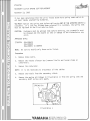
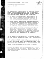
Official Recall Campaign - BR250F (1982)
g~
Steering and Slider Modifications
583-008
September 15, 1982
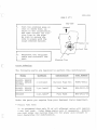
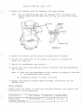
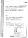
The affected model, indicated below, may have three possible
defects involving the outer steering arms, the sheet metal
plate which positions the lower portion of the main steerin g
shaft, and the forward edge of the track slider frame.
1)
One defect i n volves insufficient reinforcement of the
outer s t eer i ng arms which control the movement of the
skis. Under severe riding conditions, these arms may
crack or break, resulting in partial loss of steering
control.
2)
Another possible defect involves inadequate penetration
o f the welds securing a sheet metal plate to the body of
the s nowmobile. This plate, which positions the lower
portion of the main steering shaft, may separate from
the body under extreme conditions, resulting in partial
loss of steering control.
3)
Another defect involves the possibility of the forward
edge of the track slider frame entering the openings
of the track.
This may occur in instances of severe
frontal impact on a track if the adjustment is too loose
(i.e., which is not adjusted to Yamaha's specifications),
res u lting in rapid deceleration of the snowmobile.
You ARE HEREBY NOTIFIED THAT ALL UNITS LISTED BELOW MUST HAVE
THE OUTER STEERING ARMS REPLACED ON BOTH SIDES. THE SHEET METAL
PLATE WHI CH ANCHORS THE LOWER PORTION OF THE MAIN STEERING
SHAFT MUST BE RIV ETED TO THE .BODY AND EXTENSION CAPS MUST BE
FITTED TO BOTH LEADING EDGES OF THE TRACK SLIDER FRAME, THESE
MODIFICATIONS MUST BE PERFORMED ON ALL MACHINES DELIVERED FROM
YAMAHA, WHETHER NOW OWNED BY THE CUSTOMER OR THE DEALER.
Owners of the affected models are being notified by mail t h at
their machines require modifi cations. They have been as k e d to
return their machines to an authorized Yamaha dealership 'co r
these modifications.
- - - - - - - - V.ll. M.lI. I-! A
MOTOR CANADA LTD.
583-008
page 2 of 7
I
Affected Units
All 1982 BR2S0F model snowmobiles between the serial numbers of
8R4-0l0l0l and 8R4-0l47ll.
I
I
Modification Procedures
A
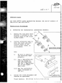
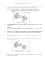
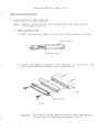
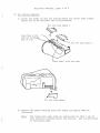
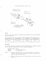
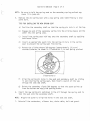
EXTENSION CAP INSTALLATION (SUSPENSION RUNNERS)
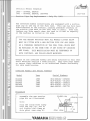
1.
Remove the long bolt from
bracket 1 located at the
leading edge of the track
slider frame.
2.
Install extension caps to
both the right and left
leading edges of the
track slider frame, as
illustrated.
I
I
I
r-IS&T
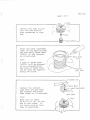
Note.:
i)
Be s ure to position
the extension caps
properly.
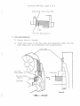
ii)
Cap 6 (8R4-47321-00)
must be fitted to
the left-hand side
and cap 7 (8R4-4732200 ) to the righthand side.
iii) See the instruction
sheet contained in
th e kit.
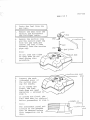
3.
Adjust the track alignment and
tension as specified.
Track tension:
\
!,,\ yC~
\(\ ~~
~ ~speNSION
2S.-v30 rom (1.0",1.2 in.)/lO kg
RUNNER
(EXTENSION CAP)
I
- ----~
S83-008
page 3 of 7
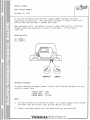
B.
REPLACEMENT OF OUTER STEERING ARMS AND RIVETING OF
STEERING SHAFT BRACKET PLATE.
-1.
Remove the primary sheave clutch, the exhaust pipe, the fuel
tank and the engine before proceeding.
i)
Secure the shroud with a suitable piece of rope to
protect against damage.
ii )
Drain the fuel tank and disconnect the fuel and oil
lines.
iii) Be sure to plug the fuel and oil lines.
iv)
Use the following special tools for clutch removal:
90890-01878
90890-01701
2.
Sheave puller
Sheave holder
v)
Disconnect all electrical cables coming from the
engine.
vi)
Disconnect both the throttle and starter cables
at the carburetor side.
Dismount the engine toge ther with the carburetor and the
air si lencer.
No-te:
Clean the engine area of the belly pan.
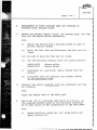
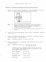
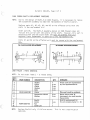
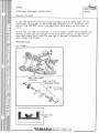
3.
Drill ten (10) 4 . 1 mm holes (#20 drill or 0.16 in.) in
the steering bracket plate at the positions indicated
by an open circle on the illustration on the next page.
NOlte. :
i)
Before drilling, punch ten (10) guide points and
apply cutting oil.
-· - · ... - · · ..... "~"'n,...A .. ,AnAITn
_ _ _ _ _ _ _ _ -'
I
I
I
I
I
I
I
S83-008
page 4 of 7
15
·1 5
15
ii )
15
(0.59 ) (0 .59 )
(0.59 )( 0 .59 )
Take care not to
damage the track
while drilling.
iii ) See the illustration on the instruction sheet
con t ained in the
kit.
Steering bracket
20
+-_++
(0.78_)
20
(0 .78)
---I'--_++-
mm (in)
x:
Spot welded
0:
4.' mm (0.16 in)
drilled hole for
rivening
I
I
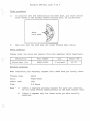
4.
Rivet the ten ( lO ~
positions illustrated
us i ng the washers and
rivets containe d in
the kit.
:r=
I
/
xo
><
0
x
OC')(
,...-~
No:te:
•
Use the six (6)
washers supplied
only at those posi
tions ind i cated
by a s olid circle
(e) on the back
side of the belly
p aiD .
i)
ii )
-
No was h ers are to
be used at the
remaining four (4)
positions indicatec by an open
circle (0).
----
VA • • A U "
...
x
•
X
®
•
~
X
• I
l
X
I •
J
•
X
-"
I
@ RIVETS
®
@
nTnt:!r.I1Nl1nA L TD. _ _ _ _ _ _ _ _
I
.I
583- 0 08
page 5 of 7
I
iii ) See t he illus tration on the i nstr uction
sheet c ontained in the k i t.
5.
Remove the old outer steering arms.
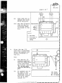
6.
Install new outer steering arms as illustrated
using the new washers,
nuts and cotter pins
contained in the kit.
No.te:
i)
Do not re-use the
old nuts, washers
and cotter pins.
ii)
The old outer
steering arms
must be
destroyed.
25 Ni'n,-{2.5m.kg,1Sft.lb}
iii ) The new' and old
outer steering arms
can be distinguished
from one another
by comparing them
with the i l lus trat ions shown opposite.
iv)
-
-
See the instruction
sheet contained in
the kit.
_ _ _ YAMAHA MOTOR CANADA LTD. _ _ _ _. _ _ _ _ -
rtt'
583-008
page 6 of 7
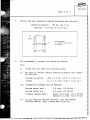
7.
I
Adjust t h e ski centre-to- centre distance and toe-out:
Centre-to-centre - 750 mrn (29.5 in. )
Toe-out - 0 "v 6 mrn (0
If
O. 23 in.)
"\I
A
Front
.
\.,- '
1. Sk i spindle center
A - C - 0 - 6 mm (0 - 0.23 in )
B
B. Ski width
8.
For reassembly, reverse the above procedure.
Note.:
i)
Bleed the air from the Autolube pump.
ii)
Be sure to adjust sheave centre-to-centre and offset
as follows:
Centre-to -centre
266 ± 2.0 mrn (10.47 ± 0.08 in. )
Offset
11.0 ± 3.0 mrn (0.43 ± 0.12 in. )
iii) Tightening torques are as follows:
iv )
-
-
-
Engine mount bolt -
3.0 m-kg {22 ft-lb V
Engine mount nut -
1 . 4 m-kg (10 ft-lb)
Primary sheave bolt -
first 10.0 m-kg (72.5 ft-lb)
second 6.0 m-kg (43.5 ft-lb)
If you require further details, see the BR250F
Service Manual (part number 8R4-28l97-70).
-
_
VAMAI-fA MOTOR
CANADA LTD. -
-
-
-
-
-
-
-
til
S83-008
•
page 7 of 7
Parts Ordering
All of the necessary parts for a complete modification are
packaged as a complete kit.
Please order the quantity of modification kits you require from
your Regional Parts Department.
MODEL
BR250F
QUANTITY
DESCRIPTION
PART NUMBER
1 kit/unit
BR250F Mod. Kit
90891-50026
D/N
$ 22.03
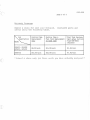
warranty Coverage
Parts Al lowance -
The normal policy of dealer net
will apply.
Labour Allowance -
$40.00 per unit.
+
10%
Claims should be 'submi tt-e d on a ' normal warranty -c,laimform
with mention of technica'l - bulletin number ,S83-008. Claim
only one unit on each warranty-' form.
'
* Subm-U:
-- -
-
a.
c..£.a..,Un oYlf.y OOIl
-
-
th0.6 e u~ you have a.c.:tJJ..a.Le.y mocU..oJ..ed
VAMA~ll.
MOTOR CANADA LTD. - - -
-
-
*
-
-
-.,
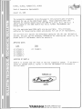
Official Recall Campaign
19 8 0 - SS440D, SR540D
1981 - SS440E, SR540E, SRX440E
S82-008
The affected models listed below are equipped with a suction
pipe cap on the top of the fuel tank . This cap may have been
overtightened at the factory, causing possible cracking of
the suction pipe neck on the fuel tank to occur.
Some fuel
leakage may thus result when the tank is filled to capacity
or the machine is tilted on its side.
YOU ARE HEREBY NOTIFIED THAT ALL MODELS LISTED BELOW
MUST BE FITTED WITH A NEW SUCTION PIPE CAP AND UNDERGO A THOROUGH INSPECTION OF THE FUEL TANK, WHICH MUST
BE REPLACED AT THE SAME TIME IF ANY SIGNS OF CRACKING
ARE FOUND. THIS MODIFICATION MUST BE PERFORMED ON
BOTH CUSTOMER - AND VEALER-OWNEV MACHINES.
Owners of the affected models are being notified by mail that
their machines require a modification.
They have been asked
to return their machines to an authorized Yamaha dealership
for this modification.
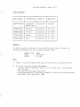
Af f ected Models and Serial Numbers
Model
Year
Serial Numbers
SS440D
SS440E
SR540D
SR540E
SRX440E
1980
1981
1980
1981
1981
8K4 - 00010l rv 005650
8L8 - 0l0l0l '" 014252
8LO-009l0l ~/ 009553
8L9-0l6l0l 'V 019113
8M6-00010l ' " 001770
Procedure
I
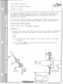
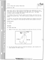
1.
I
Assemble the new suction
pipe kit as illustrated .
a1.um--<-num p--<-p e.
No t e. :
C::::;-""'a?---
Slip the large hose clamp
over the cap lip, but do
,-
no t tig ht e.n the clamp at
this point (see step 8 ) .
--~--------------------
"-MAHA
IMWl
clip
.taAge damp
19 mm
t
MOTOR CANADA LTD.
MOTEURDUCANADALTEE __________________- '
•
S 8 2- 00 8
page 2 of 5
Dra i n the f uel from t he
gas tan k.
3.
I
Remove the seat from the
machine and disconnect
ir ___ t_h_e__t_a_l_
· l_l_ l_·9_h_t__c_ a_b_l_e__
. __________
4.
Remo v e the suction line
and the s u c ti o n p ipe cap
from the gas tank and
remove the fuel filter
assemb ly from the suction
pipe cap .
rrt:;,c.a
p
~~. ~ ~ . ~,
. _._p_____________
c..,Up ·-e
.6 uc...:Uon. un.e.
c..,Up .
Not e. :
Do not lose the clips
as they must be re used during this
procedure.
I
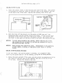
5.
n.e.c.k
Me.a
Ins pect t h e n eck
( t h readed a r e a) o f
the s uc t ion pipe
cap for cracks.
If no cracks are
found, the fuel
tank does not need
re p lacing -- proceed
step 6 .
I f cracks are f ound , the
f u el tank mua~ b e. ~e.plac.e.d
before proceeding t o step 6 .
Note. :
The instrument panel and
louvers on the SRx440E
mu st be removed before
this inspection can be
done .
e.xample. 06
~a c.lUn.g
I
flUC.tiOn. p-<.pe.
n.e.C.R
S82 - 008
page 3 of 5
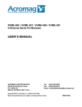
6.
I
7.
Install the fuel filter
onto the new suction
pipe assembled in step
one.
,I
i
(/
\
Cle an the neck (threaded
area) of the suction pipe
cap and apply Thre e Bond
(#1215) to the thre ad s ,
as illustrate d.
No:te:
A tube of Three Bond
(#1215) will be s hipped
to you automatically.
One tube of Three Bond
can be used for approxi mately 60 units .
r----- - -- - -- -- - - - - - - - - -"/ tuLbbe!L
8.
Install the suction
pipe onto the gas t a nk
and tighten the large
hose clamp as illustrated .
No:te:
Make sure to leave
40 mm (1.57 in . ) at t he
end of the clamp . Vo
no:t leave more or less
than is specified.
mm
cap -
S82-008
page 4 of 5
Top View
I
9.
Turn the aluminum pipe so
t hat it faces lent, as
shown i n the illustration,
and then connect the suction line to the pipe.
Be sure to secure the
line in place with the
clips removed earlier.
o
o
RubbeJL Cap
I
Fue.1. Tank.
10.
Reconnect the taillight
cable and reinstall the
seat.
Parts Ordering
The following parts are required to perform this modification:
QUANTITY
DESCRIPTION
PART NUMBER
1 kit/unit
Suction Pipe Kit
90891-50012
SS440D , SS 440E
SR540D, SR540E
1 pc./unit*
Fuel Tank
BK4-24111-00
SRX440E
1 pc./unit*
Fuel Tank
SM6-24l1l-00
MODEL
SS440D, SS440E
SR540D, SR540E
SRX 440E
Order the parts you require from your Regional Parts Department.
*
Plea~e
Tak.e Note
It i s estimated t hat onl y 5% of al l affected units will require
a new f uel tank . Order these parts only if necessary. However,
you must order one Suction Pipe Kit for every unit brought to
your dealership for modification.
•
S82-008
page 5 of 5
wa r ranty Coverage
Submit a clai m for eaQh u n~t mod~6~ed.
la b our usi ng the following table.
~
Calculate parts and
Suction Pipe
Replacerrent
only
Suction Pipe &
Fuel Tank Replacement
at same time
Fuel Tank Replacernent after Suction
Pipe has been
replaced
SS440D, SS440E
SR540D, SR540E
$8.00/unit
$11. OO/unit
$3.00/unit
SRX440E
$15.00/unit
$18.00/unit
$3.00/unit
Description
.M:xlel
*
S u bm~t
a
Qla~m
only 60n
t ho~e u n~t~
you have aQtually
mod~6~ed
*
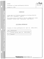
PZ480H
884-018A
Correction to clutch modification bulletin
January II, 1984
CORRECTION
Please make the following correction to bulletin 884-018,
page 3 of 4, procedure - item 2).
The primary spring contained in the kit is NOT colour coded.
Eliminate "(colour code: blue-green)" from item 2).
ADDITIONAL INFORMATION
Contents of clutch modification kit (part no:
Qty
90891-50051)
Description
1
primary spring (part no:
3
spacers
"-MAHA
___________ • M
90501-45534)
MOTOR
CANADA
LTD. _ _ _ _ _ _ _ _ _ _- '
MOTEUR DU
CANADA LTEE
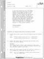
PZ480H
Primary Clutch
January 4, 1984
. page 1 of 4
It has been determined that the PZ480H
primary clutch may stick due to slight
binding of the spider fingers to the
plastic sliders and that the clutch
weights may fall toward the engine side
when the sled is lifted from the left
side. When this happens, engagement &
shift RPM may become slightly elevated.
To avoid this, the plastic sliders must
be removed and filed and a new clutch
modification kit must be installed.
These procedures must be performed during
P.D.I. of unsold units or periodic maintenance of units already retailed.
Affected Models
All PZ480H's
Procedure for removing and filing the plastic sliders
1)
Remove the primary clutch from the machine using the special
tool.
Note -
2)
Primary sheave puller part no.:
90890 - 01898
Primary sheave holder part no.:
90890-01701
Remove the clutch cap by loosening the six bolts, then
remove the primary spring.
Caution The primary spring is held under pressure by the clutch
cap. Loosen the six bolts evenly in stages to prevent the
cap from being jammed to one side.
3)
Remove the three plastic sliders by carefully inserting a
flat screwdriver under them and prying them up.
Note -
It is not necessary to remove the sliding sheave
from the spider post.
1----------- VAMAHA
•M
MOTOR CANADA LTD.
MOTEUR DU CANADA LTEE
Bulletin 584-018, page 2 of 4
4)
Using a small half-round file, remove a small amount of material
from both corners of each spider finger, as illustrated.
Note -
Before filing, place enough rags around the sliding
sheave bushing to prevent filings from entering the
sheave.
File around six corners
5)
Use compressed air to blow the metal filings and dirt out of the
clutch.
Caut i o n Wear eye protection whenever using compressed air to avoid injury.
6)
Spray contact cleaner on both sides of the sliding sheave bushing
and its contact area on the post to remove all dirt and grease.
7)
Agai n use compressed air tc blow the metal filings and dirt out
of the clutch.
8)
Check t h e p l as t ic sliders for burrs and file until smooth.
i llustra t ion below.
See
File around corner
9)
Reinstall the sliders and check for smooth movement of the spider
within the sliders.
Bulletin 584-018, page 3 of 4
Procedure for installing spacers and primary spring from kit
1)
Install the three spacers contained in the kit between the sliding
sheave and each of the clutch weights, as illustrated.
spacer here
Note -
a)
After installing the spacers, check the clearance
between all weights and rollers by pushing the
sliding sheave toward the spider. If there is no
clearance, remove the spacers.
b)
Do not forget to place washers on both sides of the
weights.
2)
In stall the new primary spring (colour code:
in the kit.
3)
Install the clutch cap and the six cap bolts.
the bolts evenly to specifica tion.
Note -
4)
Tigh teni ng torque:
blue-green) contained
Be sure to tighten
1.4 m-kg (10 ft-lb)
Reinstall t he clutch on the machine and tighten the clutch bolt
to specification.
Note -
Tightening torque:
A - 12.0 m-kg (85 ft-lb)
B 6.0 m-kg (43 ft-Ib)
Tighten t h e bol t to torque A first to seat the clutch
on the taper; then loosen the bolt a n d retorque to the
fin al specification torque B.
Sheave distance
26 7"-1 270 mm
Sh eave offset:
10.5""11.5 mm
Engagement RPM:
3,000'\13,400
Shift RPM:
6,600""7,000
Bulletin 584-018, page 4 of 4
.
\
•
Final procedure
1)
To indicate th~t the modification has been done, put three centre
punch marks on the primary sheave holding bolt, as illustrated.
Three
punch
2)
Make sure that the sled does not creep forward when idling.
Parts ordering
Please order the parts you require from your Regional Parts Department.
Description
Clutch Mod. Kit
Part Number
Qty.
Dealer Net
90891-50051
1 kit/unit
$1. 78
warranty coverage
When completing your warranty request form, make sure you clearly show:
Trouble code:
58418
Par ts:
90891-50051
Labour code:
7001
Time:
0.6 hours
Note -
a)
Submit a separate warranty request for each unit modified.
Do not claim several modifications on the same request form.
b)
Submit a request only for those units you have actually
modifi ed.
1984 EC340H (Excel III)
Front Axle Bearing Retainer
October 26, 1983
It has been determined that the front axle bearing retainer has
not been installed on affected models. This may cause damag e to
the bearing, the speedometer gear or the front axle when the
snowmobile is driven.
A front axle bearing retainer (8F3 - 4755l - 00) MUST be installed o n
all affected units mentioned below whether new or already sold .
Affected Unit Serial Range
EC340H (Excel III )
8W8 - l4655l ~
146750
Procedure
1. Inspect the right-hand front axle area of the engine comp artment
to determine whether the bearing retainer has been installed
or not.
NOTE :
a) If three plates are located ln this area, there is no need
to proceed.
b ) If one plate (2) is missing from the right-hand front axle,
proceed as fo:(lows .
.
Q)
)
Front Axle
May be
missing
@l
CD
\ 1)
Speedometer
Gear Housing
2
Front Axle
Bearing
G)
"-MAHA
L _....- - - - - - - - - - • M
Inside Bearing Retainer
MOTOR CANADA LTD.
MOTEUR DU CANADA LTEE
Bulletin S84-015, page 2 of 3
2) Remove the fancase cover by loosening the three screws.
NOTE :
The two bottom screws must be loosened first to prevent the
washer behind the fan case cover at the top screw from corning
loose .
] , . . . ; - - - - - - f) •
SECTION A-A
3) Remove the battery and the starter solenoid switch bracket.
4) Elevate the righ t side of the machine by placing a suitable box
under the right ski.
5) Remove the speedometer gear housing .
6) Install the front axle bearing retainer together with the speedometer
gear housing.
NOTE: a) Make s u re the speedometer drive coupler is properly installed
i n the speedometer gear housing .
b) Tightening torque: 2.3 kg-m (16 ft-lb).
7) Install the starter solenoid switch bracket, the battery and the
fancase cover.
Parts Order ing
Please order the number of f ront axle beraing retainers you require from
your Regional Parts Department.
Description
Part Number
Quantity
Front axle
bearing retainer
BF3-47551 - 00
1 pc/unit
Dealer Net
$ 1. 46
Bulletin S84-015, page 3 of 3
warranty
I MPORTANT:
Warranty coverage will be given only when the entire
procedure is performed.
Par t s :
Dealer net plus 10 % will be credited.
Labour:
0.5 ho urs of labour will be credited.
NOTE:
a) Bulletin number S8415 should be indicated in the trouble code area
of the warranty request form.
b) Submit a separate warranty request for each unit.
sev eral units on one request form.
Do not list
c) Submit a request only for those units in which you have actually
i ns talled a front axle bearin g retainer.
OFFICIAL RECALL CAMPAIGN -
PZ480H (1984) SNOWMOBILE
S84-023
Throttle Shafts Sticking
January 26, 1984
The affected units listed below may encounter icing of the
carburetor throttle shafts under certain riding or weather
conditions.
If this occurs the engine will not return to its
normal idle speed and partial loss of machine control could result.
This problem may be encountered while the machine is being ridden
or when first started after it has been sitting idle for a period
of time.
IN ACCORDANCE WITH THE LEGISLATION SET OUT IN THE CANADIAN MOTOR
VEHICLE SAFETY ACT, YOU ARE HEREBY NOTIFIED THAT ALL UNITS LISTED
BELOW MUST BE FITTED WITH A DEEP SNOW KIT AND THE THROTTLE SHAFTS
MUST BE CLEANED AND LUBRICATED WITH A LOW TEMPERATURE GREASE.
THIS MODIFICATION MUST BE PERFORMED ON ALL CUSTOMER AND DEALER
OWNED MACHINES AND ALL MACHINES SUBSEQUENTLY DELIVERED FROM YAMAHA.
Owners of the affected machines are being notified by mail that
their machines require a safety-related modification.
They have
been asked to return their snowmobile to an authorized Yamaha
snowmobile dealer for the modification and have been advised to
avoid riding their snowmobiles until the modification has been
carried out.
If you have not submitted a warranty registration card for any
PZ480H units you have sold, you should do so immediately.
Failure
to comply could make you liable for any damages caused due to the
above defect.
Affected Model and Serial Number Range
Model
Year
Serial number range
PZ480H
1984
8VO-019101 to 020107
L_J----------_ "-MAHA
•M
MOTOR CANADA LTD.
MOTEUR DU CANADA LTEE
,.
Bulletin S84-023, page 2 of 5
MODIFICATION PROCEDURE
1) INSTALLATION OF DEEP SNOW KIT
Note:
Before installing the kit, please read the instructions
contained in the kit.
a) Front Baffle Plate
1 ) Affix the warning label to the front baffle plate as shown,
. Baffle plate
~rning
label
2) Install the baffle plate onto the front of the hood using the
hood hinge securing screws; see illustration.
Baffle plate
Screw
Caution:
This baffle plate must be removed when the machine
is operated at temperatures greater than 0 o C.
Bulletin S84 - 023 , page 3 of 5
b) Air Shroud Sealing
1) Clean the areas of the air shroud where the three foam rubber
seals are to be affixed; see illustrations .
2
Air cowl foam rubbe r 1
lign foam 1 with cowl edge
~I
Air cowl foam rubber
2) Remove the paper backing from the seals and apply them as
indicated.
Note:
The right-rear seal must be positioned so that 3 mm of
seal material extends below the shroud;
see illustration
on following page .
Bulletin S84-023, page 4 of 5
Align foam 3 with cowl edge
Air cowl foam rubber 3
c) Fan Case Sealing
1) Remove the air shroud.
2) Clean the areas of the fan case and crankcase where the fan
case seals are to be affixed; see illustration.
Fan case
l
Fan case
foam rubber
Crankcase
Fan case foam
rubber 2
Crankcase
( rt11IllJ -_.
.tflxlrG~)
Bulletin S84-023, page 5 of 5
3) Remove the paper backing from the seals and apply them as
shown.
•
Note:
The uppermost seal adheres to the side of the fan case,
and the lower seal adheres to the crankcase.
4) Reinstall the air shroud.
2) CARBURETOR SPRAYING
R
Using a water-displacing spray such as WD -40 or silicone spray with
a long, thin nozzle attachment, heavily spray the two throttle shaft
pivot areas of both carburetors.
It is essential that all water in
these areas be removed to prevent pos~ible throttle sticking.
After
spraying, apply a heavy coat of low- temperature grease (such as
ESSO EP Arctic low-temperature lithium- base g=ease) to all throttle
shaft pivot areas.
Parts Ordering
Please order all kits you require from your Regional Parts Department.
Description
!
Deep Snow Kit
Part Number
Quantity
Dealer Net
90891-50057
1 kit/unit
$5.63 each
warranty Coverage
To obtain warranty coverage for this modification, indicate · the
following information on your warranty request form.
1) Trouble code
S8423
2) Quantity
1 per unit
3 ) Part number
90891-50057
4) Description
Deep Snow Kit
5) Labour time
0.5 hours per unit
Note:
1) Submit a separate warranty request for each unit modified .
Do not claim several modifications on the same request form.
2) Submit a request only for those units you have actually
modified.
19Ci4 pZ480H
Engine Misfiring and Erratic Headlight Operation
S84 - 024
February 29, 1984
Engine misfiring and erratic headlight operation of the affected
units may be caused by a shorting out of the handlebar wiring
harness .
This may occur at two locations . The first is where the harness
passes through the cast handlebar and fairing mount : the sharp
edges of the mount may penetrate the insulation.
The second location is where the voltage regulator wire passes between the left
body panel and the footrest plate : the wire may be pinched.
Procedures for repositioning the wires are provided below. Perform
these procedures on all affected units when they are brought in for
'.
service.
In addition, follow the procedures below if an affected
unit exhibits the symptoms described.
Affected units
All PZ480H
Procedures
A. Handlebar Wiring Harness
1) Remove the handlebar pads
and the fairing.
wiring harness
2) Remove the strap holding the
handlebar wiring harness to
the handlebar and discard
the strap.
3) Pull the harness away from
the handlebar and inspect
the wiring. Repair any
damage as required.
4) Secure the wiring harness
to the speedometer cable
using electrical tape.
Check to ensure that the
harness is no longer touch ing any sharp edges; if
necessary, use some emery
paper to take off the
sharp edges.
5) Reinstall the fairing and
handlebar pads.
L_J------------ "V-MAHA
•M
MOTOR CANADA LTD.
MQTEUR DU CANADA LTEE
Bulletin S84-024, page 2 of 2
B. Voltage Regulator Lead
1) Reposition the voltage re gulator
lead in front of the footrest
plate .
Warranty Coverage
To obtain warranty coverage for this modification, indicate the
following information on your warranty request form.
1) Trouble code
2) Labour time
Note:
S8424
0.6 hours per unit
1) Submit a separate warranty request for each unit modified.
Do not claim several modifications on the same request form .
2) Submit a request only for those units you have actually
modified .
1984 VMXs40H
C.D.I. HAGNETO STATOR PLATE
September 19, 1984
It has been determined that the water pump case CGver has not been
machined properly. This results in uneven seating of the C.D.I.
magneto stator plate and may cause the plate to become cracked
or damaged through engine vibration.
A spacer (90891-50060) which eliminates the uneven seating
must be installed on all 1984 VMXs40H units whether new or
already sold. Please contact owners of delivered units so
that this modification may be done.
Affected Units
All 1984 VMXs40H units.
Procedure
1.
First, remove the engine from the chassis. To save time,
you may choose to remove only those components which
allow the right-hand end of the motor to be tilted for
access to the recoil starter and magneto.
2.
Remove the four bolts holding the recoil starter.
3.
Remove the three bolts holding the starter pulley.
4.
Using the flywheel puller, remove the flywheel magneto
rotor and key.
5.
Using a hand impact tool, remove the magneto stator plate
bolts and check the stator for any cracks or damage.
6.
Install the spacer between the stator plate and the pump
cover as shown below.
Stator plate
Pump cover
.
L
. . . .J------_yl'MAHA
M
.
Spacer { 90891-s0060)
MOTOR CANADA LTD.
MOTEUR DU CANADA LTEE
Bulletin S85-015, Page 2 of 3
NOTE :
The spacer must be installed with the open ends positioned
as shown below.
Spacer (90891-50060)
Eump drive cover
7.
Reassembly is the reverse of disassembly.
Loctite® to the stator plate bolts.
Remember to apply
NOTE:
Reset:
(a)
Ignition Timing
(b)
Sheave centre-to-centre - 305 ± 1.5 mm (12.01 ± 0.06 in . )
(c)
Sheave offset
- 1.6 ± 0.05 mm (0.063 ± 0.002 in.)
11 ± 0.5 mm (0.433 ± 0.02 in.)
Bulletin S85 - 015, Page 3 of 3
i 70 -
i 17 .0 -
/
I
75 Nm
7.5 m -kg_ 50.6 - 54 .2 t,", b l l
/
I
7 Nm 10 .7 m -' 9_ 5 . 1 tt-l bl l
13.4 N m
11.3 m - kg. 9 .4 ft-l b l
1. Flywheel magneto
2. Flywheel pulley
3. Coil plate
Parts
Please order the number of spacers you require from your Regional
Parts Department.
DESCRIPTION
Spacer
PART NUMBER
QUANTITY
DEALER NET
90891 - 50060
Ipc/unit
$1. 97
Warr an -cy
To obtain warranty coverage for this modification, please indicate
the f o l lowing information on your warranty request:
TROUBLE CODE = S85 15
PARTS
= as indicated above
LABOUR
= 3.5 hr./unit
NOTE:
1.
.You may indicate up to 10 se r ial numbers on a single
request form provided the model name and trouble code
are the same for all units.
2.
Submit a request only for those units you have actually
modified .
ET340J, EC340J, PZ480H/J/EJ, XL540J
Shaft - 5 Suspension Improvements
August 14, 1985
The suspension components to be discussed in this bulletin were original l y
designed for use on the 1984 Pha zer mod el. Those components were then
improved for greater durability on the 1985 PZ's, ET's , EC's, and XL's . A
design change on the 1986 Shaft-5 has led to further improvements and
reliability.
Only the newly- designed 1986 parts are now available. This eliminates
confusion for those placing orders and ensures full use of all improvements.
This bulletin will explain the differences among the '84, '85, and '86 Shaft - 5
designs, and give you the necessary information for ordering and insta l ling the
proper parts if replacement should be necessary.
AFFECTED UNITS
1984
1985
All
All
All
All
A11
All PZ480H's
ET 340J ' s
EC340J' s
PZ480J's
PZ480EJ's
XL 540J ' s
LOCATION OF SHAFT - 5
Shaft-5 is located near the front of the rear suspension system. If you have a
broken or damaged Shaft-5, replac E it with the replacement kit discussed in
th i s bulletin.
FOIlWARD~
SHAFT·S
"-MAHA
L-~-------------------- IMWl
MOTOR CANADA LTD.
MOTEURDUCANADALTEE -------------------'
Bulletin S86-015, Page 2 of 4
1985 ET340J; EC340J; PZ480J/EJ;
XL540J SHAFT-5 REPLACEMENT PROCEDURE
Replace parts #1, #2, #3, #4, and #5 on the affected units with the parts in
the replacement kit. Parts #6, #7 and #8 on the affected unit must be reused
with the replacement kit.
"85 AffECTED UNIT BEFORE REPLACEMENT
'85 AFFECTED UNIT AFTER REPLACEMENT
.7
NOTE:
When installing a new Shaft-5 assembly on an 185 , use the new shaft to
push out the old one. This wil l eliminate the need to remove the entire
suspension assembly.
1985 PARTS ORDERING
NOTE:
REF.
NO.
1
2
Do not order items 1 - 5 listed below.
PART HUMBER
-
DESCRIPTION
.
QTY.
Shaft-S
Collar
Collar
Washer
Bolts
1
2
2
2
2
6
7
8
Collar
Suspension Wheel
Wash"er
1
2 ea.
2 ea.
9
Shaft-S
Collar
Nut
Cotter pin
3
~
4
S
.
10
11
12
NOTE:
90891-50061-00
ea.
ea.
ea.
ea.
1
2 ea.
REMARKS
"These parts are superseded
by the replacement kit.
Reuse these parts.
(If lost or damaged. you must
reorder these parts.)
Shaft-S replacement kit.
This kit contains items 9 rv 12.
1
1
Replace Shaft -5 only if failure occurs.
campaign.
This is not a modification
Bulletin S86-015, Page 3 of 4
1984 PZ480H SHAFT - 5 REPLAC EMENT PROCEDURE
NOTE:
Due to the design of Shaft - 5 on 1984 Phazers, it is necessary to remove
the suspension assembly to make the replacement of Shaft-5 easier.
Replace parts #1, #2, #3, #4, and #5 on the affected units with the
parts in the rep l acement kit.
Order part #6. The Shaft - 5 assembly design on 1984 Phazers does not
include this collar over the centre of the shaft. However, this part is
necessary with the new style shaft and must be ordered from your
Regional Parts Department in addition to the replacement kit.
Parts #7 and #8 on the affected unit must be reused with the replacement
kit.
'84 PHAZEIl BEFOIlE IlEPLACEMENT
'84 PHAZEIl AFTEIl IlEPLACEMENT
1984 PHAZER - PARTS ORDERING
NOTE:
REF.
NO.
1
2
3
4
5
6
7
Do not order: .items 1 - - 5 -listed below.
PART NUMBER
90387·160M7-00
8
9
10
11
12
NOTE:
Collar
Collar
Washer
Bolts
Collar
Suspension Wh eel
Washer
1
2 ea.
2 ea.
2 ea.
2 ea.
1
2 ea.
2 ea.
Shaff-5
Collar
Nut
Cotter pin
1
2 ea.
1
1
- Sha H-5
-
90891 -50061-00
QTY.
DESCRIPTION
Replace Shaft - 5 only if failure occurs.
campaign.
REMARKS
These parts are supe rsed ed
by the replacement kit.
Th is part must b e orde red.
Reuse these parts. (If
damaged, you must reorder
these parts.)
Shaff-5 replaceme nt kif.
This kif contains Items 9 rv 12.
This is not a modification
Bulletin S86-015, Page 4 of 4
WARRANTY
1985
Should this replacement be necessary within the normal warranty period, please
indicate the following information on your warranty request:
TROUBLE CODE:
PARTS:
LABOUR:
S8615
90891 -5 0061 - 00 (deal er net + 10% for handlinq will be
credited to yo ur parts account)
0.4 hours
1984
Should this replacement be necessary within the normal warranty period, please
indicate the following information on your warranty request:
~
TROUBLE CODE :
PARTS :
S8615
M~
90387 - 160j 7- 0Q (dealer net + 10% for handling will be
90891 -50061 - 00
credited to your parts account)
LABOUR:
1. 5 hours
NOTE:
J.
You may indicate up to 10 serial numbers on a sing le request form provided
the model name, model year and trouble codes are the same for all units .
2.
Submit a warranty request only for those units whose Shaft-5 has actually
been replaced.
ET340TRK
SECONDARY CLUTCH SPRING SEAT REPLACEMENT
November 13, 1985
It has been determined that the units listed below have spring seats which do
not meet Yamaha engineering standards.
YOU MUST replace the spring seat before delivering ANY OF THE AFFECTED UNITS to
customers. If a unit has already been released to a customer, the spring seat
must be replaced at the first service check.
CAUTION:
Customers must be advised that before shifting, the snowmobile mu st
be stopped and the engine at idle or damage to the transmission may
occur.
Affected Units
ET340TRK
NOTE:
81W-000623
81W-000646
81W-000651 to 000948
Be sure to modify only those'units listed.
Procedure
1.
Remove choke cable.
2.
Remove the intake silencer box (remove 3 bolts and loosen clamp on
carburetor) .
3.
Remove the carburetor.
NOTE:
It is not necessary to disconnect all the cables.
3.
Remove the V-belt from the secondary clutch.
4.
Remove the spring pin (shown in illustration 1) from the spring seat and
secondary shaft using a pin punch.
Illustration 1
VAMAHA
~-J~------------------ IMWl
MOTOR CANADA LTD.
MQTEURDUCANADALTEE -------------------'
Bulletin S86-018
NOTE:
5.
Page 2 of 3
Be sure to hold the spring seat as the secondary spring preload may
cause it to jump out.
Replace the old spring seat with a new spring seat identified by a blue
paint mark.
TIPS FOR INSTALLING THE NEW SPRING SEAT
a)
Position the secondary shaft so that the spring pin hole is at the top.
b)
Engage one end of the secondary spring into the sliding sheave and the
other into the spring seat.
c)
Install the spring seat half way onto the secondary shaft by applying
continuous force.
d)
Insert an appropriate punch into the spring pin hole in the spring
seat to prevent the spring seat from moving.
e)
Rotate the sliding sheave 160 degrees (approximately 1/2 turn)
counterclockwise, as shown in illustration 2, to set spring preload.
Illustration 2
6.
f)
Align the spring pin holes in the seat and secondary shaft by sliding
in and rotating the spring seat, then insert a punch all the way
through the seat and shaft.
g)
Rotate the secondary clutch 180 degrees so that the punch points up
from the bottom and apply the parking brake.
Insert the new spring pin contained in the kit through the spring seat to
lock the seat onto the secondary shaft.
NOTE:
7.
Wiggle the punch to align the holes in the seat and shaft.
Reinstall the carburetor, silencer box, choke cable, belt and guard.
Bulletin S86018
Page 3 of 3
,
PARTS ORDERING
Please order the kits you require from your
Region~l
PART NUMBER
DESCRIPTION
QUANTITY
90891 -50071
Spri ng kit seat
1 kit/unit
Parts Department .
REMARKS
Includes:
spring seat .. 1 pc.
ramp shoe .... 3 pcs.
spring pin ... 1 pc.
DLR. NET
$9.79
WARRANTY
To obtain warranty coverage for this modification, please indicate the
following information on your warranty request form:
TROUBLE CODE:
PARTS
LABOUR
S8618
90891-50071
0.5 HRS.
NOTE:
1.
You may indicate up to 10 serial numbers on a single request form provided
the model name and trouble codes are the same for all units.
2.
Submit a warranty request only for those units you have modified.
3.
You must enclose the defective spring seat with your warranty request form.
SR540K, XL540K
HOOD STOPPER WASHER
November 27, 1985
It has been determined that the hood stopper washer has been installed
incorrectly on some units. This may cause the washer to catch in the front
baffle plate when the hood is opened and closed.
When performing P.D.I. and set-up, be sure to check the position of the hood
stopper washer and reposition it as per illustration 1 if incorrectly
i r1 S t a 11 ed .
Affected Units
ALL SR540K' S
ALL XL540K ' s
INCORRECT
CORRECT
Warranty Coverage
To obtain warranty coverage, please indicate the following· information on your
warranty request form.
TROUBLE CODE:
LABOUR CODE :
LABOUR HOURS:
7090
5613
0.1 HRS.
NOTE:
1.
You may indicate up to ten serial numbers on a single request form provided
the model name and trouble codes are the same for all units.
2.
Submit a warranty request only for those units you have modified.
t---------- V'AMAHA
•M
MOTOR CANADA LTD .
MOTEUR DU CANADA LTEE
CF300K
ADDITIONAL IDLER WHEEL INSTALLATION
586-021
December 23, 1985
It has been determined during our early product testing that, under certain
conditions, slider wear on the CF300K may be excessive. To eliminate this
possibility, YOU MUST install the additional idler wheels on this model at
P.D.1.
If the unit has been retailed and is in use, please contact your customer and
arrange to have the unit brought in for this modification. If the unit has
been used, check the sliders for wear and if the wear is beyond the limit,
also replace the sliders.
Affected Units
A11 CF300K s
I
ADDITIONAL WHEEL
LOCATION
APPLY LOCTITE
TIGHTENING TORQUE
Nm (1. 7 m-kg,
12 ft-lb)
LIDER WEAR LIMIT
10
ITII1
VAMAHA
-------------------- IMWl
MOTOR CANADA LTD.
MOTEURDUCANADALTEE __________________- '
Bulletin 586-021
Page 2 of 2
PARTS ORDERING
PART NUMBER
DE SCR I PT ION
QUANTITY
8K2 -4 7320 -00
Suspension
Wheel Compo
2 pes/unit
DEALER NET
$ 15.21
-------------- ------------- ------------ -----------93306 - 00416
Beari ng
2 pes/unit
$ 4.75
-------------- ------------- ------------ -----------Circlip
99009 -42500
2 pes/unit
$ 0.90
-------------- ------------- ------------ -----------90201 - 08681
Washer
2 pes/unit
$ 1.42
-------------- ------------- ------------ -----------90109 - 08559
Bolt
2 pes/unit
$
0.24
WARRANTY
To obtain warranty coverage for this modification, please indicate the
following information on your warranty request form.
TROUBLE CODE:
PARTS
LABOUR
58621
As Listed
0. 2 Hrs
Note:
1.
Submi t a warranty request form only for tho se units you have modified .
2.
For units requiring slider replacement:
- You must submit a separate request form for each unit, including the
the old parts.
- The unit must have been registered.
- No consideration will be given to requests received by Toronto Warranty
Department after January 31, 1986.
EX570L
SPECIAL PREDELIVERY SERVICE PRECAUTIONS
S87-016
October 29, 1986
When the oil tank is first filled on the affected units, there may be a long
delay before the oil level registers in the sight tube. This is because of the
viscosity of the oil and the fact that the sight tube is dry. The simple
procedure, below, eliminates this delay.
The affected units are filled with coolant at the factory, but levels must be
checked during predelivery. The correct topping up procedure is also outlined
below.
In addition, this bulletin gives the proper procedure for bleeding the cooling
system. This procedure is to be used any time the cooling system is drained.
AFFECTED UN ITS
All EX570L
PROCEDURE
OIL LEVEL SIGHT TUBE
1.
Before filling the oil tank, disconnect the sight tube from the T-fitting.
OIL TANK
2.
Fill the tube from a squirt can containing Yamalube 2, then reconnect the
sight tube and fill the oil tank.
L......--.J~--------_
•
"AMAHA
M
MOTOR CANADA LTD.
MOTEUR DU CANADA LTEE
Bulletin S87-016, Page 2 of 3
COOLING SYSTEM FILLING
1.
Check the coo l ant levels in the recovery tank and filler neck. Add coolant
as necessary to bring the levels to the FULL mark on the recovery tank and
to the top of the filler neck. Replar.p the recovery tank filler cap.
FILLER CAP
FIUER NECK
RECOVERY
TANK
/
2.
With the track off the ground, run the engine at 4000 rpm until the
thermostat opens and the coolant -freely circulates. If the coolant level
decreases in the filler neck, with the engine running, add coolant until
the level is once again at the top of the filler neck, and replace the cap.
WARNING:
To avoid being burned by hot coolant, before removing the filler
cap, always be sure to carefully relieve any pressure build-up if
the engine has been running.
WARNING:
Av01d contact with the moving track. Entanglement in the machinery
of shop towels, clothing, or body parts could result in serious
injury.
COOLING SYSTEM BLEEDING PROCEDURE
If, for any reason, the cooling system is drained, it is essential when
refil l ing the system that all air be removed, using the following method.
1.
Remove the seat and both filler caps, and add coo lant as necessary to bring
the levels to the FULL mark on the recovery tank and to the top of the
filler neck. Replace the recovery tank cap.
HEAT EXCHANGER ILEED IOLT
Bulletin S87-016, Page 3 of 3
,
COOLING SYSTEM BLEEDING PROCEDURE CONT'D
2.
Loosen (do not remove) the bleed bolt at the left side of the rear heat
exchange r and allow coolant to run out .until all air bubbles disappear from
the coolant.
3.
Tighten the bleed bolt and replace the lost coolant.
CYLINDER HEAD BLEED BOLT
I
THERMOSTAT HOUSING
4.
Loosen (do not remove) the bleed bolt on the cylinder head and, once again,
allow coolant to run out until all air bubbl es disappear.
5.
Tighten the bleed bolt and replace the lost coolant.
WARNING:
6.
To avoid being burned by hot coolant, before removing the filler
cap. always be sure to carefull y relieve any pressure build-up if
the engine has been running.
With the track off the ground, run the engine at 4000 rpm until the
thermostat opens and the coolant freely circulates. If the coolant level
decreases in the filler pipe, with the engine running, add coolant until
the level is once again at the top of the filler neck, and replace the cap
and seat.
WARNING:
Avoi d contact with the moving track. Entangl ement in the machinery
of shop towels , clothing~ or body parts coul d result in serious
injury.
WARRANTY INFORMATION
These procedures are part of normal predelivery service.
allowances applies.
No special warranty