1
Sun StorEdge™ 3000 Family
Configuration Service 2.4
User’s Guide
Sun Microsystems, Inc.
www.sun.com
Part No. 817-3337-17
March 2007, Revision A
Submit comments about this document at: http://www.sun.com/hwdocs/feedback
Copyright © 2002–2007 Dot Hill Systems Corporation and others, 2200 Faraday Avenue, Suite 100, Carlsbad, California 92008, USA.
All rights reserved.
Sun Microsystems, Inc. and Dot Hill Systems Corporation may have intellectual property rights relating to technology embodied in this product
or document. In particular, and without limitation, these intellectual property rights may include one or more of the U.S. patents listed at
http://www.sun.com/patents and one or more additional patents or pending patent applications in the U.S. and other countries.
This product or document is distributed under licenses restricting its use, copying distribution, and decompilation. No part of this product or
document may be reproduced in any form by any means without prior written authorization of Sun and its licensors, if any.
Third-party software is copyrighted and licensed from Sun suppliers.
Parts of the product may be derived from Berkeley BSD systems, licensed from the University of California. UNIX is a registered trademark in
the U.S. and in other countries, exclusively licensed through X/Open Company, Ltd.
Sun, Sun Microsystems, the Sun logo, Sun StorEdge, AnswerBook2, docs.sun.com, Java, and Solaris are trademarks or registered trademarks of
Sun Microsystems, Inc. in the U.S. and in other countries.
Netscape is a trademark or registered trademark of Netscape Communications Corporation in the United States and other countries.
U.S. Government Rights—Commercial use. Government users are subject to the Sun Microsystems, Inc. standard license agreement and
applicable provisions of the FAR and its supplements.
DOCUMENTATION IS PROVIDED “AS IS” AND ALL EXPRESS OR IMPLIED CONDITIONS, REPRESENTATIONS AND WARRANTIES,
INCLUDING ANY IMPLIED WARRANTY OF MERCHANTABILITY, FITNESS FOR A PARTICULAR PURPOSE OR NONINFRINGEMENT,
ARE DISCLAIMED, EXCEPT TO THE EXTENT THAT SUCH DISCLAIMERS ARE HELD TO BE LEGALLY INVALID.
Copyright © 2002–2007 Dot Hill Systems Corporation et d’autres, 2200 Faraday Avenue, Suite 100, Carlsbad, Californie 92008, Etats-Unis.
Tous droits réservés.
Sun Microsystems, Inc. et Dot Hill Systems Corporation peuvent avoir les droits de propriété intellectuels relatants à la technologie incorporée
dans le produit qui est décrit dans ce document. En particulier, et sans la limitation, ces droits de propriété intellectuels peuvent inclure un ou
plus des brevets américains énumérés à http://www.sun.com/patents et un ou les brevets plus supplémentaires ou les applications de brevet
en attente dans les Etats-Unis et dans les autres pays.
Ce produit ou document est protégé par un copyright et distribué avec des licences qui en restreignent l’utilisation, la copie, la distribution, et la
décompilation. Aucune partie de ce produit ou document ne peut être reproduite sous aucune forme, par quelque moyen que ce soit, sans
l'autorisation préalable et écrite de Sun et de ses bailleurs de licence, s’il y en a.
Le logiciel détenu par des tiers, et qui comprend la technologie relative aux polices de caractères, est protégé par un copyright et licencié par des
fournisseurs de Sun.
Des parties de ce produit pourront être dérivées des systèmes Berkeley BSD licenciés par l’Université de Californie. UNIX est une marque
déposée aux Etats-Unis et dans d’autres pays et licenciée exclusivement par X/Open Company, Ltd.
Sun, Sun Microsystems, le logo Sun, Sun StorEdge, AnswerBook2, docs.sun.com, Java, et Solaris sont des marques de fabrique ou des marques
déposées de Sun Microsystems, Inc. aux Etats-Unis et dans d’autres pays.
Netscape est une marque de Netscape Communications Corporation aux Etats-Unis et dans d’autres pays.
LA DOCUMENTATION EST FOURNIE “EN L’ÉTAT” ET TOUTES AUTRES CONDITIONS, DECLARATIONS ET GARANTIES EXPRESSES
OU TACITES SONT FORMELLEMENT EXCLUES, DANS LA MESURE AUTORISEE PAR LA LOI APPLICABLE, Y COMPRIS NOTAMMENT
TOUTE GARANTIE IMPLICITE RELATIVE A LA QUALITE MARCHANDE, A L'APTITUDE A UNE UTILISATION PARTICULIERE OU A
L’ABSENCE DE CONTREFAÇON.
Contents
Preface
xix
1.
Introduction
1
2.
Before You Begin
3
Installing the Software
Example Screens
3
3
Superuser Privileges
4
Sun StorEdge 3120 SCSI Array
4
Sun StorEdge 3000 Family JBODs
3.
4
Starting and Setting Up Sun StorEdge Configuration Service
Starting Sun StorEdge Configuration Service
5
6
▼
To Start Sun StorEdge Configuration Service on a UNIX Host
▼
To Start Sun StorEdge Configuration Service on a Microsoft Windows
Host 7
The Main Window
7
The Menu, Toolbar, and Tabs
Menu Bar
Toolbar
Tabs
6
7
8
8
10
iii
Device Icons
10
Physical (Hard) Drives
Navigating
10
10
If Console Locks Up During Use
▼
To Stop Sun StorEdge Configuration Service
Setup Procedures
▼
To Add Servers
▼
To Delete Servers
▼
To Log In and Out
▼
To Assign a Server to Manage a Controller
▼
12
18
19
▼
24
To Manually Delete a Server Using the Terminal Window
To Configure Agent Parameters
▼
To Enable JBOD Support
26
To Verify Storage Configurations
▼
To Save the Logical Drive Configuration
27
29
31
▼
To Create Solaris Host Partitions
▼
To Create Windows 2000 and Windows 2003 Host Partitions
▼
To Create IBM AIX Host Logical Volumes
▼
To Create HP-UX Host Logical Volumes
What to Do Next
31
33
34
35
Full Configuration
37
Configuring Logical Drives and Logical Volumes
Logical Drives
Logical Volumes
24
24
▼
Creating Host Partitions
iv
21
22
To Unassign the Managing Server
▼
11
11
Changing a Server Assignment
4.
11
38
38
38
Sun StorEdge 3000 Family Configuration Service 2.4 User’s Guide • March 2007
32
Maximum Number of Supported Logical Drives, Logical Partitions, and LUN
Assignments 38
▼
To Use Standard Configuration
Media Scan
▼
39
44
To Use Custom Configuration
The New Configuration Option
44
46
Before You Use New Configuration
▼
▼
To Prepare for Logical Drives Larger Than 253 Gbyte
▼
To Create and Partition a Logical Drive Using New Configuration
To Create and Partition a Logical Volume
Media Scan
▼
To Clear a Configuration
▼
To Log Out of the Configuration Level
▼
To Delete (Unmap) a Host LUN
60
61
62
62
To Save a Configuration to a Backup File
Loading the Configuration
63
64
LUN Filtering (FC and SATA Only)
Overview
57
60
To Add or Change (Map) a Host LUN
▼
49
59
▼
Configuration File
49
59
Host LUN Assignments
5.
46
65
65
Assigning a LUN Filter
67
▼
To Access the LUN Filter View
67
▼
To Add a New Host Manually
67
▼
To Add an HBA Device Manually
▼
To Remove Standard Host Mapping
▼
To Assign a LUN Filter
72
▼
To Delete a LUN Filter
74
69
71
Contents
v
6.
Monitoring the Array
The Main Window
Device Status
75
76
77
Degraded State
Critical State
78
Device Capacities
Online Help
78
79
79
Tree View of Product Configurations
Groups
79
79
The Monitoring Process
81
Auto Discovery Options
82
Viewing Detailed Device Information
View Group
83
View Server
84
View HBA Card
86
View Controller
87
Controllers Tab
88
Physical Drives Tab
Enclosure Info Tab
View FRU
88
89
89
View Controller Parameters
View Logical Drive
View Physical Drive
View Enclosure
83
90
93
94
95
Environmental State
96
Power Supply and Fan Location
98
SAF-TE and SES Temperature Sensor Locations
SES Voltage Sensors
vi
101
Sun StorEdge 3000 Family Configuration Service 2.4 User’s Guide • March 2007
100
SATA MUX and SATA Router Information
Battery Information
▼
103
To Verify the In-Service Date When Replacing a Battery
View FRU
Agent Options Management
Event Log
108
108
109
Event Log File
110
▼
To Filter Events
▼
To Write Events to a Log File for an IBM AIX Host
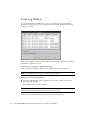
Event Log Window
Severity Levels
Save Report
114
View Report
117
111
111
112
113
In-Band and Out-of-Band Storage Management
117
▼
To Use Out-of-Band Management
▼
To Remove an Array From Out-of-Band Management
Managing Storage Through the Web
Web Browser Requirements
UNIX OS
119
122
123
123
123
Microsoft Windows OS
Setting Up the Array
▼
105
107
Array Administration Progress
7.
102
124
124
To Access the Console From the Web Browser
Maintaining the Array
125
127
Array Administration Activities
128
▼
To Check Parity
▼
To Schedule a Parity Check
▼
To Scan Physical Disks for Bad Blocks (Media Scan)
128
130
132
Contents
vii
▼
To Stop a Media Scan on a Logical Drive or Physical Drive
Failed Drives
136
▼
To Automatically Rebuild a Drive Using a Standby Drive
▼
To Rebuild a Device Without a Standby Drive
▼
To Check the Progress of the Rebuilding Process
▼
To Manually Rebuild a Failed Drive
▼
To Restore a Logical Drive Configuration
Controller Maintenance Options
8.
136
137
138
138
140
143
▼
To Reset the Controller
▼
To Shut Down the Controller
▼
To Mute the Controller Beeper
▼
To Bring a Failed Controller Back Online
▼
To Display Performance Statistics
▼
To Get Controller Boot Time
▼
To Convert a Dual Controller Array to a Single Controller Array
Updating the Configuration
▼
143
144
144
145
145
146
149
To Add a Logical Drive to a Logical Volume
Media Scan
153
155
▼
To Add a Logical Volume From Existing Logical Drives
▼
To Delete a Logical Drive or Logical Volume
157
The Logical Drive/Logical Volume Number
158
▼
To Create a Partition
155
160
The Logical Drive/Logical Volume Number
162
▼
To Delete a Partition
▼
To Expand the Capacity of a Logical Drive or Logical Volume
162
The Logical Drive/Logical Volume Number
▼
147
To Add a Logical Drive or Logical Volume From New Logical Drives
▼
viii
135
166
To Add Physical Drives to an Existing Logical Drive
Sun StorEdge 3000 Family Configuration Service 2.4 User’s Guide • March 2007
167
164
150
The Logical Drive/Logical Volume Number
▼
To Copy and Replace Physical Drives
168
168
The Logical Drive/Logical Volume Number
170
▼
To Scan in New Hard Drives (SCSI only)
170
▼
To Download RAID Controller Firmware
172
▼
To Upgrade Firmware and Boot Record
Downloading Firmware for Devices
175
176
▼
To Upgrade Firmware on Hard Drives
▼
To Upgrade Firmware on SAF-TE/SES Devices
▼
To Change Controller Parameters
▼
To Save Changed Values
Channel Tab
RS 232 Tab
184
Cache Tab
185
Drive I/F Tab
Host I/F Tab
179
180
189
190
192
Redundancy Tab
Peripheral Tab
194
195
To View Environmental Status for the Controller
Network Tab
198
Protocol Tab
200
▼
To Mute the Controller Beeper
▼
To Assign or Change Standby Drives
Available Servers
▼
197
201
202
204
To Edit a Server Entry
204
Updating the Object Data Manager on an IBM AIX Host
▼
177
182
Disk Array Tab
▼
176
To Update the ODM
206
206
Contents
ix
A.
RAID Basics
209
RAID Terminology Overview
Logical Drive
210
Logical Volume
210
Local Spare Drive
210
Global Spare Drive
Channels
211
RAID Levels
214
RAID 0
215
RAID 1
216
RAID 1+0
RAID 3
218
RAID 5
219
209
210
217
Advanced RAID Levels
220
Local and Global Spare Drives
220
Having Both Local and Global Spares
B.
Monitoring JBODs
222
223
▼
To Enable JBOD Support
▼
To View Component and Alarm Characteristics
Environmental State
223
225
Power Supply and Fan Location
226
SAF-TE Temperature Sensor Locations
▼
To Download Firmware for Devices
▼
To Discover a Drive
Solaris OS
Linux OS
x
226
227
227
227
228
Sun StorEdge 3000 Family Configuration Service 2.4 User’s Guide • March 2007
225
Microsoft Windows OS
HP-UX OS
229
IBM AIX OS
C.
228
229
Using the Cluster Configuration (SCSI Only)
Planning the Cluster Configuration
233
Cluster Configuration Requirements
▼
D.
234
To Set Up Cluster Configuration
234
Determining Host Worldwide Names (Fibre Channel and SATA Only)
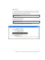
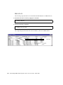
▼
To Determine the HBA WWN
Solaris OS
239
HP-UX OS
240
241
IBM AIX OS
242
▼
To Determine the FC Array WWNN
243
▼
To Determine the FC Array WWPN
244
Email and SNMP
How SNMP Works
245
246
SNMP Trap Messages
246
Agents and Managers
247
Management Information Base (MIB)
SNMP Objects
247
247
SNMP Request Types
SNMP Security
239
239
Linux and Microsoft Windows OS
E.
233
248
248
Using Sun StorEdge Configuration Service to Send SNMP Traps
▼
To Send Email Messages for Each Server
▼
Setting Up Servers to Send Traps
Microsoft Windows Servers
250
250
253
253
Contents
xi
▼
To Check the Community String for a Microsoft Windows Host
▼
To Specify the Trap Recipient for a Microsoft Windows Host
▼
To Set Up a Solaris Host
▼
To Set Up a Linux Host
▼
To Set Up an HP-UX Host
▼
To Set Up an IBM AIX Host
254
256
256
257
258
Sending SNMP Traps Without Using Sun StorEdge Configuration Service
258
F.
G.
Troubleshooting
259
Error Codes and Messages
Error Codes
267
268
Error and Status Messages
286
Installation and Program Prompts
Glossary
Index
xii
300
305
313
Sun StorEdge 3000 Family Configuration Service 2.4 User’s Guide • March 2007
253
Tables
TABLE 3-1
Main Window Toolbar Icons 9
TABLE 3-2
Main Window Tabs
TABLE 4-1
Maximum Number of Supported Logical and Physical Drives, Partitions, and LUN
Assignments 39
TABLE 4-2
Default Stripe Size Per Optimization Mode 42
TABLE 4-3
Default Stripe Size Per Optimization Mode 53
TABLE 6-1
Device Color and Symbol Status
TABLE 6-2
Two-Server Group Colors
TABLE 6-3
Sun StorEdge 3310 SCSI Array and Sun StorEdge 3320 SCSI Array SAF-TE Temperature
Sensor Locations 100
TABLE 6-4
Sun StorEdge 3510 FC Array and Sun StorEdge 3511 SATA Array SES Temperature Sensor
Locations 101
TABLE 6-5
Event Log Location
TABLE 6-6
Event Record Fields
TABLE 6-7
Minimum Web Browser Requirements for UNIX OS
TABLE 6-8
Minimum Web Browser Requirements for Microsoft Windows OS
TABLE 8-1
Default Stripe Size Per Optimization Mode 152
TABLE 8-2
Change Controller Parameters That Require a Reset
TABLE 8-3
Default Stripe Size Per Optimization Mode (Kbyte) 187
TABLE A-1
RAID Level Overview
214
TABLE A-2
Advanced RAID Levels
220
TABLE B-1
Sun StorEdge 3120 SCSI Array SAF-TE Temperature Sensor Locations 226
10
77
81
110
113
123
124
180
xiii
TABLE G-1
Severity Field 268
TABLE G-2
Major Field
268
TABLE G-3
Minor Field
269
TABLE G-4
System Drive State Errors 270
TABLE G-5
Disk State Errors 270
TABLE G-6
SAF-TE State Errors 271
TABLE G-7
Tape State Errors
TABLE G-8
Redundancy State Errors 273
TABLE G-9
Internal State Errors 273
TABLE G-10
Device State Errors 274
TABLE G-11
Initialization State Errors 274
TABLE G-12
Client Parameter Errors
TABLE G-13
Open Transport Errors
275
TABLE G-14
Close Transport Errors
275
TABLE G-15
Memory Allocation Errors
TABLE G-16
Transport Field Errors
TABLE G-17
Main Communications Errors
TABLE G-18
Communications Link 277
TABLE G-19
Communications Async 277
TABLE G-20
Communications Security 277
TABLE G-21
Timeout Errors
TABLE G-22
Administration Errors 278
TABLE G-23
Firmware Download Errors
TABLE G-24
System Shutdown Errors 279
TABLE G-25
Set Config Errors 280
TABLE G-26
Controller Event Errors 280
TABLE G-27
Drive Side Event Errors 281
TABLE G-28
Host Side Event Errors
TABLE G-29
Logical Drive Event Errors
TABLE G-30
Generalized Target Event Errors
xiv
271
274
275
276
276
277
279
282
282
283
Sun StorEdge 3000 Family Configuration Service 2.4 User’s Guide • March 2007
TABLE G-31
Server Manage/Monitor Event Error
286
TABLE G-32
Substituted Values 286
TABLE G-33
Error/Status Messages 287
TABLE G-34
Installation and Program Prompts 300
Tables
xv
xvi
Sun StorEdge 3000 Family Configuration Service 2.4 User’s Guide • March 2007
Figures
FIGURE 5-1
Example of LUN Filtering
66
FIGURE 6-1
Sun StorEdge 3310 SCSI Array and Sun StorEdge 3320 SCSI Array Power Supply and Fan
Location 99
FIGURE 6-2
Sun StorEdge 3510 FC Array and Sun StorEdge 3511 SATA Array Power Supply and Fan
Location 99
FIGURE 6-3
In-Band Management 118
FIGURE 6-4
Out-of-Band Management
FIGURE 8-1
Copying and Replacing Physical Drives
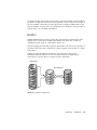
FIGURE A-1
Logical Drive Including Multiple Physical Drives
FIGURE A-2
Allocation of Drives in Logical Drive Configurations 211
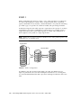
FIGURE A-3
Partitions in Logical Drive Configurations 212
FIGURE A-4
Mapping Partitions to Host ID/LUNs
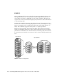
FIGURE A-5
Mapping Partitions to LUNs Under an ID 213
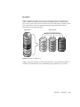
FIGURE A-6
RAID 0 Configuration 215
FIGURE A-7
RAID 1 Configuration 216
FIGURE A-8
RAID 1+0 Configuration 217
FIGURE A-9
RAID 3 Configuration 218
FIGURE A-10
RAID 5 Configuration 219
FIGURE A-11
Local (Dedicated) Spare
FIGURE A-12
Global Spare 221
FIGURE A-13
Mixing Local and Global Spares 222
118
168
210
213
221
xvii
FIGURE B-1
Sun StorEdge 3120 SCSI Array Power Supply and Fan Location 226
FIGURE E-1
Object Identifier of a MIB Variable
xviii
249
Sun StorEdge 3000 Family Configuration Service 2.4 User’s Guide • March 2007
Preface
This guide explains how to use Sun StorEdge™ Configuration Service to configure,
monitor, and manage the Sun StorEdge 3000 family arrays. For information about
installing Sun StorEdge Configuration Service, refer to the Sun StorEdge 3000 Family
Software Installation Guide.
This guide also references Sun StorEdge Diagnostic Reporter, a companion utility of
Sun StorEdge Configuration Service used for sending and receiving system
messages from the hosts and arrays. For information about installing Sun StorEdge
Diagnostic Reporter, refer to the Sun StorEdge 3000 Family Software Installation Guide.
For information about using Sun StorEdge Diagnostic Reporter, refer to the Sun
StorEdge 3000 Family Diagnostic Reporter User’s Guide.
Unless otherwise specified, the Sun StorEdge 3120 SCSI array, Sun StorEdge 3310
SCSI array, Sun StorEdge 3320 SCSI array, Sun StorEdge 3510 FC array, and Sun
StorEdge 3511 SATA array are referred to as the array or arrays.
This guide is written for experienced system administrators who are familiar with
Sun hardware and software products.
xix
How This Book Is Organized
This book covers the following topics:
Chapter 1 introduces Sun StorEdge Configuration Service features.
Chapter 2 lists steps to follow to ensure that the array has been configured properly
before you install and use Sun StorEdge Configuration Service.
Chapter 3 contains procedures for setting up Sun StorEdge Configuration Service.
Chapter 4 provides instructions for configuring the array.
Chapter 5 explains how to create a LUN filter to maintain large Fibre Channel
networks that share common storage (FC and SATA Only).
Chapter 6 explains how to monitor the array.
Chapter 7 explains how to maintain the integrity of the array.
Chapter 8 explains how to change or add to the current array configuration.
Appendix A provides basic redundant array of independent disks (RAID)
information.
Appendix B explains how to monitor a standalone JBOD.
Appendix C provides information about setting up a cluster configuration (SCSI
Only).
Appendix D explains how to determine the host worldwide name. (FC and SATA
Only).
Appendix E explains how to set up full event monitoring and email notification
capabilities.
Appendix F provides troubleshooting suggestions for a list of symptoms.
Appendix G contains a list of Sun StorEdge Configuration Service error codes and
messages.
The Glossary provides RAID terminology and definitions used throughout the
product documentation.
xx
Sun StorEdge 3000 Family Configuration Service 2.4 User’s Guide • March 2007
Using UNIX Commands
This document might not contain information on basic UNIX® commands and
procedures such as shutting down the system, booting the system, and configuring
devices. Refer to the following for this information:
■
Software documentation that you received with your system
■
Solaris™ operating system documentation, which is at
http://docs.sun.com
Shell Prompts
Shell
Prompt
C shell
machine-name%
C shell superuser
machine-name#
Bourne shell and Korn shell
$
Bourne shell and Korn shell superuser
#
Preface
xxi
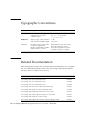
Typographic Conventions
Typeface1
Meaning
Examples
AaBbCc123
The names of commands, files,
and directories; on-screen
computer output
Edit your.login file.
Use ls -a to list all files.
% You have mail.
AaBbCc123
What you type, when contrasted
with on-screen computer output
% su
Password:
AaBbCc123
Book titles, new words or terms,
words to be emphasized.
Replace command-line variables
with real names or values.
Read Chapter 6 in the User’s Guide.
These are called class options.
You must be superuser to do this.
To delete a file, type rm filename.
1 The settings on your browser might differ from these settings.
Related Documentation
The following table contains a list of related software documentation. For a complete
list of all related documentation, refer to the Sun StorEdge 3000 Family Installation,
Operation, and Service Manual for your array.
Title
Part Number
Sun StorEdge 3120 SCSI Array Release Notes
816-7955
Sun StorEdge 3310 SCSI Array Release Notes
819-7109
Sun StorEdge 3320 SCSI Array Release Notes
817-7660
Sun StorEdge 3510 FC and 3511 SATA Array Release Notes
817-6597
Sun StorEdge 3000 Family 2.4 Software Installation Guide
817-3764
Sun StorEdge 3000 Family RAID Firmware 4.2 User’s Guide
817-3711
Sun StorEdge 3000 Family Diagnostic Reporter 2.4 User’s Guide
817-3338
Sun StorEdge 3000 Family CLI 2.4 User’s Guide
817-4951
Sun StorEdge 3000 Family RAID Controller Firmware Migration Guide
819-6573
xxii Sun StorEdge 3000 Family Configuration Service 2.4 User’s Guide • March 2007
Accessing Sun Documentation
All Sun StorEdge 3000 family array documentation is available online at the
following location:
http://www.sun.com/products-n-solutions/hardware/docs/
Network_Storage_Solutions/Workgroup/
You can view, print, or purchase a broad selection of Sun documentation at:
http://www.sun.com/documentation
Contacting Sun Technical Support
For late-breaking news and troubleshooting tips, review the release notes for your
array, available at the locations shown in “Accessing Sun Documentation” on
page xxiii.
If you have technical questions about this product that are not answered in the
documentation, go to:
http://www.sun.com/service/contacting
To initiate or check on a USA-only service request, contact Sun support at:
800-USA4SUN
To obtain international technical support, contact the sales office of each country at:
http://www.sun.com/service/contacting/sales.html
Preface
xxiii
508 Accessibility Features
The Sun StorEdge documentation is available in 508-compliant HTML files that can
be used with assistive technology programs for visually impaired personnel. These
files are provided on the Documentation CD for your product as well as on the
websites identified in the Section “Accessing Sun Documentation” on page xxiii.
Additionally, the software and firmware applications provide keyboard navigation
and shortcuts, which are documented in the user's guides.
Sun Welcomes Your Comments
Sun is interested in improving its documentation and welcomes your comments and
suggestions. You can submit your comments by going to:
http://www.sun.com/hwdocs/feedback
Please include the title and part number of your document with your feedback: Sun
StorEdge 3000 Family Configuration Service 2.4 User’s Guide, part number 817-3337-17.
xxiv
Sun StorEdge 3000 Family Configuration Service 2.4 User’s Guide • March 2007
CHAPTER
1
Introduction
This section provides a brief overview of Sun StorEdge Configuration Service
features.
Note – For brevity, Sun StorEdge Configuration Service is sometimes referred to as
the program.
Sun StorEdge Configuration Service is a sophisticated program based on the Java™
programming language, which brings together storage configuration, maintenance,
and monitoring tools into one application for centralized administration of the array.
From a single console located on a network, system administrators can initialize
network storage, change configurations, monitor status, and schedule routine
maintenance through an intuitive graphical user interface (GUI).
Administrators can also dynamically allocate, reallocate, or expand capacity as
storage requirements continually change with evolving network-wide storage
demands.
In the event of a change in status, the program sends alerts by console display, email,
or alphanumeric pager. It can also send alerts to any Simple Network Management
Protocol (SNMP) enterprise manager, for example HP OpenView.
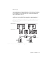
Sun StorEdge Configuration Service consists of two components:
■
Sun StorEdge Configuration Service agent – Monitors attached disk storage devices
and reports their status to the console about these devices. The agent software
needs to be installed on each individual server in the network that is part of Sun
StorEdge Configuration Service.
■
Sun StorEdge Configuration Service console – Displays the information reported by
the agents. The console also provides remote configuration and management of
the devices from a single workstation. The console needs to be installed on a
computer that manages the servers on your network.
1
You can have a maximum of 10 clients connected to the same Sun StorEdge
Configuration Service agent. Clients include Sun StorEdge Configuration Service
consoles and Sun StorEdge Diagnostic Reporter daemons.
2
Sun StorEdge 3000 Family Configuration Service 2.4 User’s Guide • March 2007
CHAPTER
2
Before You Begin
This chapter contains important information you need to be aware of before you use
Sun StorEdge Configuration Service. Topics covered in this chapter include:
■
■
■
■
■
“Installing the Software” on page 3
“Example Screens” on page 3
“Superuser Privileges” on page 4
“Sun StorEdge 3120 SCSI Array” on page 4
“Sun StorEdge 3000 Family JBODs” on page 4
Installing the Software
For installation instructions, refer to the Sun StorEdge 3000 Family Software Installation
Guide.
Example Screens
Many example screens are provided throughout this guide to demonstrate the
program. These screens might identify either the Sun StorEdge 3310 SCSI array, Sun
StorEdge 3320 SCSI array, Sun StorEdge 3510 FC array, or Sun StorEdge 3511 SATA
array in the output. Unless specifically noted that a function, and therefore its
example screen, is for a specific array only, all arrays apply.
3
Superuser Privileges
You must be superuser (administrator) to run the Sun StorEdge Configuration
Service console.
Sun StorEdge 3120 SCSI Array
The only Sun StorEdge Configuration Service array functions supported for the Sun
StorEdge 3120 SCSI array are viewing component and alarm characteristics and
determining drive failure. See “Monitoring JBODs” on page 223 for procedures
related to the Sun StorEdge 3120 SCSI array.
Sun StorEdge 3000 Family JBODs
The only Sun StorEdge Configuration Service array functions supported for Sun
StorEdge 3000 family JBODs are viewing component and alarm characteristics and
determining drive failure. See “Monitoring JBODs” on page 223 for procedures
related to Sun StorEdge 3000 family JBODs.
Note – JBOD (Just a Bunch of Disks) is an array connected directly to a server with
no controllers.
4
Sun StorEdge 3000 Family Configuration Service 2.4 User’s Guide • March 2007
CHAPTER
3
Starting and Setting Up Sun
StorEdge Configuration Service
This chapter explains how to start Sun StorEdge Configuration Service and provides
an overview of the main window, which displays attached storage devices. It also
describes procedures you need to follow before you can configure and monitor an
array. Topics covered in this chapter include:
■
■
■
“Starting Sun StorEdge Configuration Service” on page 6
■
“To Start Sun StorEdge Configuration Service on a UNIX Host” on page 6
■
“To Start Sun StorEdge Configuration Service on a Microsoft Windows Host”
on page 7
■
“The Main Window” on page 7
“Setup Procedures” on page 11
■
“To Add Servers” on page 12
■
“To Delete Servers” on page 18
■
“To Log In and Out” on page 19
■
“To Assign a Server to Manage a Controller” on page 21
■
“To Unassign the Managing Server” on page 24
■
“To Configure Agent Parameters” on page 24
■
“To Verify Storage Configurations” on page 27
■
“To Save the Logical Drive Configuration” on page 29
■
“To Create Solaris Host Partitions” on page 31
■
“To Create Windows 2000 and Windows 2003 Host Partitions” on page 32
■
“To Create IBM AIX Host Logical Volumes” on page 33
■
“To Create HP-UX Host Logical Volumes” on page 34
“What to Do Next” on page 35
5
Starting Sun StorEdge Configuration
Service
This section explains how to start Sun StorEdge Configuration Service.
Note – You must be superuser (administrator) to run the console.
Because the console does not receive event alerts unless it is running, after
configuring the array, always leave Sun StorEdge Configuration Service running in
its minimized mode on the console workstation. Or, instead of keeping the console
running, you can use Sun StorEdge Diagnostic Reporter, a companion utility of Sun
StorEdge Configuration Service that runs as a background service that sends
messages from the hosts and array to specified email addresses. For details, refer to
the Sun StorEdge 3000 Family Diagnostic Reporter User’s Guide. For another method of
receiving event alerts, see “Sending SNMP Traps Without Using Sun StorEdge
Configuration Service” on page 258.
Note – You cannot use Sun StorEdge Configuration Service and the Sun StorEdge
CLI at the same time to configure, monitor, or maintain an array.
Note – For Sun StorEdge Configuration Service to view and manage an array, each
HBA card must be connected to the primary controller.
▼
To Start Sun StorEdge Configuration Service on
a UNIX Host
At the command prompt, type:
# ssconsole
6
Sun StorEdge 3000 Family Configuration Service 2.4 User’s Guide • March 2007
▼
To Start Sun StorEdge Configuration Service on
a Microsoft Windows Host
For Windows 2000, choose Start → Programs → Sun StorEdge 3000 Family →
Configuration Service.
For Windows 2003, choose Start → All Programs → Sun StorEdge 3000 Family →
Configuration Service.
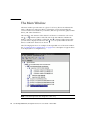
The Main Window
When the program initializes for the first time, the main window is blank. The Add
Server window is displayed, prompting you to add servers to the Managed Servers
list of the console you are using. For details on adding servers, see “To Add Servers”
on page 12.
Whenever you start the program after the first time and after you have selected
Managed Servers, the main window displays server icons for the servers on the
Managed Servers list.
The Menu, Toolbar, and Tabs
The main window includes a menu bar, tabs, and a toolbar for access to key
functions.
Chapter 3
Starting and Setting Up Sun StorEdge Configuration Service
7
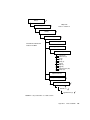
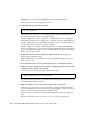
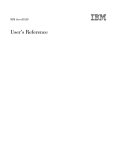
Menu Bar
The following figure shows the main menu options.
File
View
Server List Setup
Event Log
Login
Logout
View Group
View Server
View HBA Card*
View Controller
View Logical Drive
View Physical Drive
View Enclosure
View FRU
Save Report
View Report
Exit
Configuration
Standard Configure
Custom Configure
Array Administration
Rebuild
Save Configuration
Load Configuration
Parity Check
Schedule Parity Check
Media Scan
Configure Host/WWN (FC and SATA only)
LUN Filter Properties (FC and SATA only)
Controller Assignment
Controller Maintenance
Download FW for Devices
View Peripheral Device
Array Admin in Progress
Agent Options Management
Display HDD under LD
Help
Contents
About sscsConsole
*Is displayed only for out-of-band management.
Toolbar
Located below the menu bar, the toolbar provides icons that give you quick access to
commonly used functions. Select an icon to activate its function. Toolbar icons are
displayed both as active or inactive (grayed), depending on what resources are
available in the main window.
8
Sun StorEdge 3000 Family Configuration Service 2.4 User’s Guide • March 2007
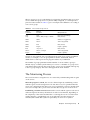
TABLE 3-1
Icon
Main Window Toolbar Icons
Description
Server List Setup. Adds servers that the console manages, edits
server information, or designates that an available server is
managed.
View Event Log. View events such as storage device status
changes, hardware status changes, or operational notifications.
Save Event Log. Displays the Save Event Log File dialog box,
which enables you to conveniently save the Event Log without
having to go to the Event Log window.
Delete Event Log. Manually deletes the contents of the
eventlog.txt file. (The program accumulates events until the
limit of 10,000 is reached, at which time the Event Log is
automatically reduced to the most current 500 events.)
Save Report. Creates an XML file containing data about each of
the storage components on the selected server as of the current
date.
Standard Configure. Creates one or more logical drives with
one RAID level on the selected array controller. Use when you
want a predefined configuration where Sun StorEdge
Configuration Service automatically configures storage.
Custom Configure. Provides multiple choices for configuring or
reconfiguring logical drives or logical volumes with varying
RAID levels on the selected array controller.
Use when you want to manually define configuration,
including setting or changing controller IDs and parameters
and defining or modifying RAID sets and standby drives.
Note – The Configuration menu commands and toolbar icons might be temporarily
disabled if an array administration process, such as parity checking, is running. The
menu command is also deactivated when the console is refreshing its inventory on
the server. A satellite dish symbol is attached to the server icon during the refresh
process.
Chapter 3
Starting and Setting Up Sun StorEdge Configuration Service
9
Tabs
Located below the toolbar, tabs enable you to quickly move to other Sun StorEdge
Configuration Service views.
TABLE 3-2
Main Window Tabs
Tab
Description
Click to go to the main Sun StorEdge Configuration Service
window.
Click to go to LUN Filter View. (Fibre Channel and SATA only.)
Device Icons
See “To Verify Storage Configurations” on page 27 for a description of typical device
icons displayed for a configured array.
Physical (Hard) Drives
As the array becomes fully configured, the main window displays multiple
components. The physical drives that make up the logical drives are displayed by
default; however, to make the main window more manageable to navigate, you can
choose not to display the physical (hard) drives by deselecting View → Display
HDD under LD.
Navigating
The program follows standard Java programming language keyboard and
navigation operation.
10
Sun StorEdge 3000 Family Configuration Service 2.4 User’s Guide • March 2007
If Console Locks Up During Use
On UNIX systems, if the console locks up during use, you can stop Sun StorEdge
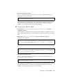
Configuration Service, and then close and reopen the window without affecting the
agent.
▼ To Stop Sun StorEdge Configuration Service
1. At the command prompt, type:
# ssconsole stop
2. Run the program again.
The window is displayed again without affecting the agent.
Setup Procedures
This section contains the following setup procedures, which you need to follow
before you can configure and monitor an array:
■
■
■
■
■
■
■
■
■
■
■
■
“To
“To
“To
“To
“To
“To
“To
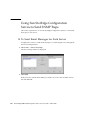
“To
“To
“To
“To
“To
Add Servers” on page 12
Delete Servers” on page 18
Log In and Out” on page 19
Assign a Server to Manage a Controller” on page 21
Unassign the Managing Server” on page 24
Configure Agent Parameters” on page 24
Verify Storage Configurations” on page 27
Save the Logical Drive Configuration” on page 29
Create Solaris Host Partitions” on page 31
Create Windows 2000 and Windows 2003 Host Partitions” on page 32
Create IBM AIX Host Logical Volumes” on page 33
Create HP-UX Host Logical Volumes” on page 34
Chapter 3
Starting and Setting Up Sun StorEdge Configuration Service
11
▼
To Add Servers
You need to assign a server to manage a controller. Before you can configure a
server, you need to add it to the Managed Servers list through Server List Setup.
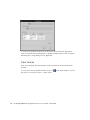
1. Start Sun StorEdge Configuration Service if it is not already running.
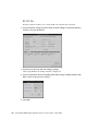
2. Choose File → Server List Setup.
The Server List Setup window is displayed.
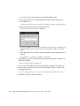
3. (Optional) Organize the servers into groups:
Depending on how many servers you have and where they are located, it might be
helpful to organize them into groups. For example, if you have multiple servers in
separate storage rooms, you might want to create groups based on location.
a. Click Groups in the Server List Setup window.
The Group List Setup window is displayed. Type a name in the Group Name field
and click Add.
12
Sun StorEdge 3000 Family Configuration Service 2.4 User’s Guide • March 2007
b. To delete a group, select the group name from the Available Groups list and
click Delete.
c. When you are finished adding and deleting groups, click OK.
The Server List Setup window is displayed.
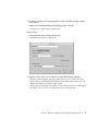
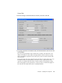
4. Add a server:
a. Click Add under the Available Servers list.
The Add Server window is displayed.
b. Type the name of the server in the Server name field and press Return.
The Server name identifies the server. If this name is in your network’s name
server database, Sun StorEdge Configuration Service determines the server’s IP
address and displays it in the IP Address field.
If the program cannot find an IP address for the name, the name was either typed
incorrectly or has not been recorded in the server’s name database.
Chapter 3
Starting and Setting Up Sun StorEdge Configuration Service
13
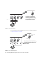
c. If required, type the server’s TCP/IP address in the IP Address field.
Storage management can be enabled in-band using fibre channel or SCSI host
connections or out-of-band through the Ethernet port. For details on using
TCP/IP for out-of-band management, see “In-Band and Out-of-Band Storage
Management” on page 117.
If the program has not already displayed the IP address (as described in the
previous step), type the IP address manually.
Selecting Get IP Address by Name, located below the IP Address field, is another
method of having the program search for the IP address and display it
automatically. As mentioned in the previous step, it works only if your network
has a name server database and you have typed the server name as it is recorded
in the database. Otherwise, you must type the IP address manually.
d. (Optional) To set up Sun StorEdge Configuration Service so that a password is
not required to monitor the server, type the ssmon password that was assigned
when Sun StorEdge Configuration Service was installed.
See “To Log In and Out” on page 19 for more information on passwords.
5. Select or Deselect Automatic Discovery of servers:
a. Select No for Auto Discovery if you need a very secure environment where
access even to server inventory data is restricted.
When you select No, the program does not retrieve server information when
starting up. The server’s icon appears color-coded white (instead of active purple)
to indicate it is undiscovered. When you double-click an undiscovered server, Sun
StorEdge Configuration Service prompts you for the ssmon user password.
Optionally, you can also select the server and select File → Login.
Select Yes for Auto Discovery to retrieve all information available about this
server when the console is started.
b. If you select Yes for Auto Discovery, type the same monitor password that was
typed earlier when the ssmon user was set up on the server (or group of servers
if you have a domain or a DNS tree).
Once the server(s) have been established using Auto Discovery, you do not need
to type the ssmon password when you log in to Sun StorEdge Configuration
Service; you automatically have monitoring privileges. However, whenever you
choose a command to perform administration or configuration activities, you are
prompted with a login dialog box to change your level of security by typing the
password for either the ssadmin or ssconfig user that was established earlier.
c. Click OK.
14
Sun StorEdge 3000 Family Configuration Service 2.4 User’s Guide • March 2007
6. (Optional) Set email addresses:
a. If you want Sun StorEdge Configuration Service to send event messages using
email, select the Mailing Lists tab and continue with the following directions.
You might want to type your own email address and the addresses of selected
users for the purpose of receiving information about events on the server.
Note – Instead of keeping the console running in the foreground, you can use Sun
StorEdge Diagnostic Reporter, a companion utility of Sun StorEdge Configuration
Service that runs as a background service that sends messages from the hosts and
array to specified email addresses. For details, refer to the Sun StorEdge 3000 Family
Diagnostic Reporter User’s Guide. To ensure that Sun StorEdge Configuration Service
receives email, see “Email and SNMP” on page 245 for information on setting traps.
For another method of receiving event alerts, see “Sending SNMP Traps Without
Using Sun StorEdge Configuration Service” on page 258. You can also use the Sun
StorEdge Automated Diagnostic Environment (StorADE) application to monitor the
status of your array.
b. For each user, type an email address in the Mail Address field.
Chapter 3
Starting and Setting Up Sun StorEdge Configuration Service
15
c. In the Severity list box, scroll through the list of severity levels and choose
from the following options:
Critical – A message that requires intervention by the network administrator, such
as failure of a device, power supply, or fan.
Warning – Messages that generally indicate internal program events. If you see a
large number of these messages, it might mean that there is a problem with the
server or the network.
Informational – Messages about the devices on the server that do not require
intervention by the network administrator.
Whatever level you choose, you receive event messages for that level and any
other levels at a higher severity. If you choose Informational, for example, you are
notified of any critical event. Conversely, if you want to be notified of only critical
situations, select Critical, and you are not notified of any Informational or
Warning events.
d. Click Add to List.
To delete a user from the list, select the mail address and click Delete from List.
e. Specify the mail server to be used.
Note that the Setup Mail Server button toggles with Change Mail Server,
depending on whether a mail server has been defined previously.
For new setups, click Setup Mail Server. A Mail Server Setup window similar to
the following is displayed.
f. Type the IP address or name of the Simple Mail Transfer Protocol (SMTP) mail
server that is delivering the email messages to the destination addresses
specified earlier, and click OK.
The Add Server window is displayed showing the Mailing Lists tab.
7. Complete the Add Server function:
16
Sun StorEdge 3000 Family Configuration Service 2.4 User’s Guide • March 2007
a. (Optional) If you want this server to be part of a group, select the Grouping tab.
The Add Server window is displayed.
b. Select the Group list box to view the choices available, select a group, and click
OK.
8. If you want to add more servers, repeat Steps 3 through 7 for each server.
9. Move the servers you want this console to control to the Managed Servers list.
■
If you want this console to manage all the available servers, click Add All located
at the top of the dialog box.
■
To move individual servers to the managed column, select each server
individually and click Add located between the two list boxes.
■
If during the process of adding servers, modifications need to be made, see “To
Edit a Server Entry” on page 204.
10. When you are finished adding servers, click OK to return to the main window.
Note – If the array is attached to multiple hosts and an agent is installed on each
host, each host’s IP address must be entered and added to the Managed Servers list.
Chapter 3
Starting and Setting Up Sun StorEdge Configuration Service
17
▼
To Delete Servers
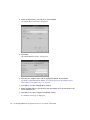
1. Choose File → Server List Setup.
The Server List Setup window is displayed.
2. Select the server you want to delete from the Managed Servers list.
3. Click Remove.
The server is moved to the Available Servers list.
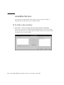
4. Click Delete.
18
Sun StorEdge 3000 Family Configuration Service 2.4 User’s Guide • March 2007
▼
To Log In and Out
The log in and log out functions provide security within the program.
Administrative functions require access logins and passwords to prevent the
possibility of one administrator reallocating or removing storage resources
belonging to other clients and hosts without authorization.
After installing Sun StorEdge Configuration Service, you should have assigned
separate passwords for the following three levels of security:
■
ssmon – Represents the monitoring level of the software; it displays alerts from
the controller.
■
ssadmin – Represents the administration level of the software; it provides access
to Rebuild, Parity Check, and Schedule Parity Check functions, as well as
monitoring.
■
ssconfig – Represents the configuration level; it provides access to the
configuration commands and all aspects of the program.
Note – In the event that one of these usernames is already in use, either modify the
existing username, use one of the other Sun StorEdge Configuration Service
usernames, or combine the two roles.
For more information on setting up users and passwords, refer to the Sun StorEdge
3000 Family Software Installation Guide.
Note – See Step 4d under “To Add Servers” on page 12 for information on how to
set up Sun StorEdge Configuration Service so that monitoring does not require the
ssmon password.
Chapter 3
Starting and Setting Up Sun StorEdge Configuration Service
19
1. To log in, choose File → Login, and type the assigned password for the specified
level of security.
If the ssmon password was specified when the server was added, you do not have to
log in to monitor the server. If the ssmon password was not specified when the
server was added, whenever the console starts up, you need to log in as ssmon to
monitor the server.
Maintain continuous access only as the monitoring user. When you select a
command that requires the administration or configuration level, a login dialog box
is displayed and you log into that level with the appropriate password. After
completing your activity, log out.
2. To log out, choose File → Logout.
When you log out from the administration or configuration level, you are given the
option of logging out to the monitoring mode or logging out from the server entirely.
20
Sun StorEdge 3000 Family Configuration Service 2.4 User’s Guide • March 2007
▼
To Assign a Server to Manage a Controller
To manage and monitor an array, the agent needs to have access to a host logical unit
number (LUN) mapped to a partition of a logical drive assigned to the primary
controller of the array. The agent ignores all host LUNs mapped to a partition of a
logical drive assigned to a secondary controller in a redundant configuration of an
array. See “RAID Basics” on page 209 for a discussion of logical drives and LUNs.
Note – If the same array is connected to multiple servers, it is possible to have the
agent running on each of these servers trying to manage and monitor the same array.
Due to a restriction on monitoring commands sent to the array controller by only
one server at a time, some monitoring commands might fail if sent simultaneously
by multiple servers. This could cause inaccurate reporting or the processes to stop
responding. To prevent this from happening, the agent can be configured to enable
and disable array monitoring on a server.
Perform the following procedure to assign a server to manage an array.
Note – Sun StorEdge Configuration Service can monitor and manage up to 32
arrays at one time. However, console response time can decrease as the number of
arrays increases.
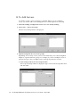
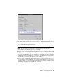
1. Make sure all directly attached servers were added following the directions in “To
Add Servers” on page 12.
This ensures that all Host names are present under Controller Assignments.
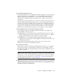
2. From the main window, choose Array Administration → Controller Assignment.
The Assign Server to Manage a RAID Controller window is displayed.
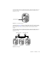
3. Select the controller that you want to manage.
Chapter 3
Starting and Setting Up Sun StorEdge Configuration Service
21
4. Select a server from the Server to manage this controller list and click Apply.
This enables the selected server to manage an array controller. It also disables all
other servers listed from managing the same array.
5. Click Close to close the view.
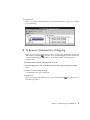
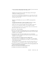
As shown in the following example, the main window shows the controller device
icons only under the server where the monitoring is enabled for this array.
Changing a Server Assignment
When you assign a server to manage a controller, information regarding the
managing server is produced. Sun StorEdge Configuration Service stores this
information on a controller and uses it to keep track of the managing server. In the
event a server is shut down, for maintenance for example, and you try to assign
22
Sun StorEdge 3000 Family Configuration Service 2.4 User’s Guide • March 2007
another server to manage the controller, Sun StorEdge Configuration Service reads
the stored server information from the controller and warns you that the controller is
being managed already.
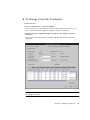
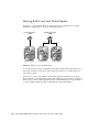
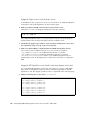
You can view the managing server name by choosing the firmware application menu
called “view and edit Host luns → Edit Host-ID/WWN Name List.” (Refer to the
Sun StorEdge 3000 Family RAID Firmware User’s Guide for your array for information
about accessing the firmware application.)
The server name is stored in
hexadecimal values for the ASCII
character set.
If you want to change a server assignment, for example, because you are moving an
array to a new location, before you move the array, you need to unassign the
managing server following the steps in “To Unassign the Managing Server” on
page 24.
If you have already moved the array, when the array starts up, you might see a
warning message that the controller is already being managed by another server.
Because the “force” option doesn’t unassign the agent of the original server, only
override the current server assignment after you have unassigned the original
managing server. If you do not manually unassign the original server, it continues to
monitor and manage the unit along with the new server.
After you have unassigned a server, you can also manually delete the server
following the steps in “To Manually Delete a Server Using the Terminal Window” on
page 24.
Chapter 3
Starting and Setting Up Sun StorEdge Configuration Service
23
▼
To Unassign the Managing Server
1. From the main window, choose Array Administration → Controller Assignment.
2. Select the array controller for which you want to unassign a server.
3. From the Server to manage this controller list, select none, and click Apply.
4. Click Close to confirm.
5. Select the server you want to manage the controller following the steps in “To
Assign a Server to Manage a Controller” on page 21.
▼ To Manually Delete a Server Using the Terminal Window
Refer to the Sun StorEdge 3000 Family RAID Firmware User’s Guide for your array for
information about accessing the firmware application.
1. From the Main Menu, choose “view and edit Host luns → Edit Host-ID/WWN
Name List → sscsMgr → Delete Host-ID/WWN Name List.”
2. Choose Yes to confirm.
▼
To Configure Agent Parameters
Agent parameters specify how you want to connect to your storage. This section
provides steps to configure parameters such as polling time, periodic device
discovery time, smart monitoring, out-of-band storage management, and enabling
JBOD support.
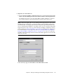
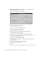
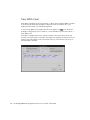
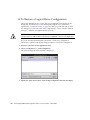
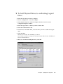
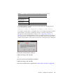
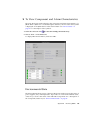
1. From the main window, choose View → Agent Options Management.
The Agent Options Management window is displayed.
Note – Agent Options Management might not be available if one or more groups
are configured and one of them is selected in the main window. To enable it, select
an icon other than a group, and click View.
24
Sun StorEdge 3000 Family Configuration Service 2.4 User’s Guide • March 2007
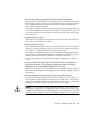
2. For Monitoring Frequency, type the interval time in seconds that you want to poll
for status.
This value is the interval between successive polling for any status change of
devices, controllers, and enclosure monitoring by the agent. The default value is 60
seconds. If you want the console to update more frequently with device status
changes, decrease this value.
Note – Increasing the polling interval could negatively impact error messaging
under heavy I/O load.
3. For Periodic Device Discovery Time, type the value in minutes you want to check
for new devices.
The periodic device discovery value is used to determine how often each device ID
is scanned for a new device. The default value of 0 specifies not to scan for new
devices. Note that device IDs are scanned less frequently as the numerical value
increases.
Conversely, device IDs are scanned more frequently as the numerical value
decreases. Five minutes is the minimum value.
Chapter 3
Starting and Setting Up Sun StorEdge Configuration Service
25
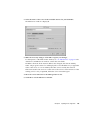
4. For Interval of trap generation for an event, type the amount of time in seconds
between the sending of each trap message.
If the value is 60 seconds or greater, a message is sent at that interval, for that
particular trap, until the event is cleared or corrected. For example, if a fan fails, a
message regarding that fan failure is sent every 60 seconds until fixed.
If the value is 0, Sun StorEdge Configuration Service (and therefore Sun StorEdge
Diagnostic Reporter) sends only one message regarding that particular event. For
example, if a fan fails, only one email is sent.
5. For Timeout of heartbeat lost, set the amount of time in minutes to wait between
the sending of failed server messages.
The default value is 15 minutes; the value range is 1 to 30 minutes.
6. To Enable SMART Monitoring, select the check box.
SMART monitoring is a method for hard drives to report predicted failures. Most
disk vendors supply drives with this feature. The agent monitors this feature by
issuing an unsolicited request sense. SMART monitoring can be turned off if this
request causes conflicts with the underlying host operating system device drivers.
For more information on SMART monitoring, refer to the Sun StorEdge 3000 Family
RAID Firmware User’s Guide for your array.
7. To Enable JBOD support, see “To Enable JBOD Support” on page 26.
8. The parameters under Controller Primary Agent Information, including the
Password fields, pertain to out-of-band management.
See “In-Band and Out-of-Band Storage Management” on page 117 for information
about configuring these parameters.
9. If you have changed any of the previous options, click OK to save your changes.
10. Click Close to finish the procedure.
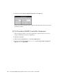
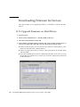
▼ To Enable JBOD Support
Use Just a Bunch of Disks (JBOD) support only when you have a JBOD connected
directly to the server. This enables you to monitor the peripheral device condition
and events. If you have a JBOD connected to the RAID array, the RAID controllers
monitor the JBOD condition and events for you.
Note – Enabling JBOD support could impact I/O.
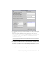
1. From the main window, choose View → Agent Options Management.
The Agent Options Management window is displayed.
26
Sun StorEdge 3000 Family Configuration Service 2.4 User’s Guide • March 2007
2. Select Enable JBOD support.
For details on monitoring a JBOD, see “Monitoring JBODs” on page 223.
▼
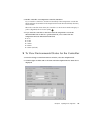
To Verify Storage Configurations
Once you have installed Sun StorEdge Configuration Service and have added all the
servers for storage that you want managed, you need to verify the storage
configurations.
Note – Most arrays are shipped preconfigured. If you want to completely remove
the existing configuration and start over, see “Full Configuration” on page 37. If you
want to change the current configuration or add to it, see “Updating the
Configuration” on page 149.
1. Make sure the server icon is online (that is, the server symbol is purple).
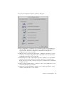
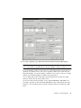
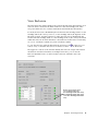
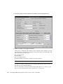
2. Observe the main window and check the storage configuration.
3. If you have multiple managed servers, select the server you want to check.
If the server icon is not purple, determine the server’s state (see TABLE 6-1). If the
server’s icon has a satellite dish attached to it
, the server might be in the
discovery process and is available after a short delay.
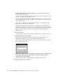
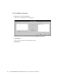
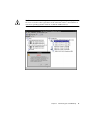
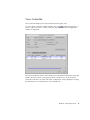
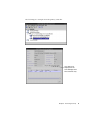
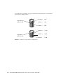
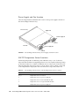
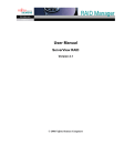
4. Click the container symbol
you want to check.
that appears to the left of the server whose storage
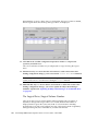
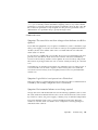
The program graphically displays each controller connected to the server as shown
in the following figure.
Chapter 3
Starting and Setting Up Sun StorEdge Configuration Service
27
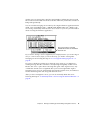
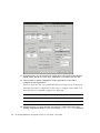
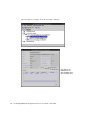
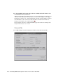
5. To see other details, click the container symbol
storage you want to check.
next to the controller whose
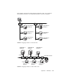
If the array has not yet been configured, no logical drives (LUNs for controllers) are
displayed.
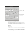
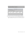
If the array has been fully configured, the Sun StorEdge Configuration Service
displays its associated devices. It looks similar to the devices displayed in the
following example.
Managing server
Array
Secondary controller
Partitioned logical drive
Logical drive
Enclosure
Available physical
drives
Primary controller
Selecting the container symbol
assigned physical drives.
to the left of any logical drive displays its
Note – You can choose to view the physical (hard) drives that make up the logical
drives by selecting or deselecting View → Display HDD under LD.
Your configuration might differ dramatically from that shown in the previous figure
depending on the products you have installed.
If the array is not configured, see “Full Configuration” on page 37 for instructions on
configuring it.
6. Check the RAID level and logical drive structure.
28
Sun StorEdge 3000 Family Configuration Service 2.4 User’s Guide • March 2007
7. If the array is already configured and the configuration meets your needs,
continue with the next section.
If you would like to change the configuration, see “Full Configuration” on page 37.
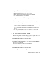
▼
To Save the Logical Drive Configuration
Even though logical drive configuration information is stored on controllers and on
the physical drives attached to them, extreme circumstances, such as fire can occur,
causing damage to both the controller and the drives. Keep multiple backup copies
of your current logical drive configuration on some form of external media other
than the array. Keep at least one backup copy in a vault or secured location off site.
A backup copy of the configuration enables you to restore the configuration to a new
controller without having to completely reconfigure the array. If you do not have a
backup copy of the current configuration, data could be lost. The saved
configuration includes controller parameter settings and LUN mapping.
Always save your controller configuration to a file whenever you:
■
Install a new storage system enclosure or change the SCSI ID for the controller in
an existing enclosure
■
Replace a controller
■
Reconfigure or add logical drives to a controller
■
Rebuild the data from a failed drive to a standby drive
To restore a configuration from a file, see “To Restore a Logical Drive Configuration”
on page 140.
1. Select the controller with the configuration you want to save.
Chapter 3
Starting and Setting Up Sun StorEdge Configuration Service
29
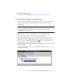
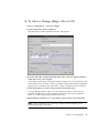
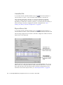
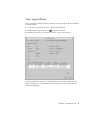
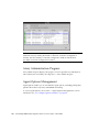
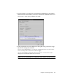
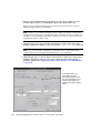
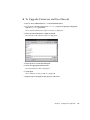
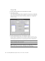
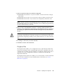
2. Choose Configuration → Save Configuration.
The Save Configuration window is displayed.
3. Navigate to the required drive and folder to locate the configuration file(s) to be
updated, indicated by a .cfg extension.
Save the file(s) to a diskette or a drive external to the array. That is, maintain copies
of these configuration files off site.
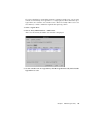
4. Specify the configuration file name and click Save.
The Save Configuration window is displayed.
5. Type a description of the configuration you are saving and click OK.
The controller configuration information is saved to a .cfg file.
30
Sun StorEdge 3000 Family Configuration Service 2.4 User’s Guide • March 2007
Creating Host Partitions
When you are satisfied with your storage configuration, you can partition the new
device through the OS.
▼
To Create Solaris Host Partitions
The following steps are general guidelines. For detailed information, read about
creating partitions and file systems in your Sun Solaris OS manual.
1. For the Sun StorEdge 3310 SCSI array or the Sun StorEdge 3320 SCSI array only,
make sure the Solaris OS can recognize multiple logical unit numbers (LUNs)
under the same ID. You might need to modify /kernel/drv/sd.conf for
additional LUN assignments. For information on how to modify this file, refer to
the Sun StorEdge 3000 Family Installation, Operation, and Service Manual for your array.
2. Make sure the Solaris OS recognizes the new device and LUNs. For detailed steps,
refer to the Sun StorEdge 3000 Family Installation, Operation, and Service Manual for
your array.
3. Label a new device by typing:
# format
The format command displays the system disk as well as other drives attached to
the array.
A new device must be labeled with the format command before it can be set up for
use by the array. When the format command is initiated, the devices that are
available for use are displayed.
Chapter 3
Starting and Setting Up Sun StorEdge Configuration Service
31
4. Select the device to be used.
Label the device if prompted.
5. Type the word partition to view the existing partition table.
After typing partition, you must type print to view the existing partition table.
6. Edit the partition table as necessary and label it if changes are made.
7. Create file systems on the partitions using the newfs command.
8. Mount the file systems by using the mount command or by editing /etc/vfstab
and using the mountall command.
▼
To Create Windows 2000 and Windows 2003
Host Partitions
The following steps are general guidelines; for detailed information, refer to your
Windows 2000 and Windows 2003 documentation.
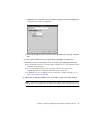
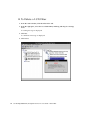
1. For Windows 2000, choose Start → Settings → Control Panel → Administrative
Tools → Computer Management → Disk Management.
For Windows 2003, choose Start → Administrative Tools → Computer Management
→ Disk Management.
Make sure you can see the new drives marked by the disk icon
Management.
under Disk
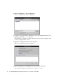
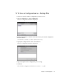
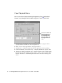
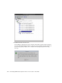
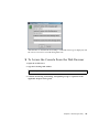
2. Right-click the disk for which you want to write a signature, and select Write
Signature.
Right-click the disk for which
you want to write a signature.
3. Select the disk for which you want to create a partition, and click OK.
32
Sun StorEdge 3000 Family Configuration Service 2.4 User’s Guide • March 2007
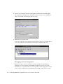
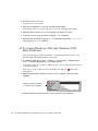
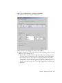
4. Right-click the drive (where the drive capacity is shown), and select Create
Partition.
Right-click on the drive for which
you want to create a partition.
5. Respond appropriately to the partition wizard prompts.
▼
To Create IBM AIX Host Logical Volumes
When you are satisfied with your storage configuration, you need to create at least
one logical volume on the server.
The following steps are general guidelines. For detailed information, read about
creating logical volumes in your AIX OS manual.
1. Determine that the drives are being recognized by the host by typing:
# lspv
Ensure that the disks have been assigned a PVID (physical volume identifier). This
information displays in the second column. If no PVID is assigned, the column
displays “None.”
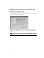
2. If no PVID is assigned, open smitty and choose Devices → Fixed Disks → Change
/Show Characteristics → Assign Physical Volume Identifier.
3. In smitty, create a volume group.
Choose System Storage Management → Logical Volume Manager → Volume Groups
→ Add a Volume Group.
4. In smitty, create a file system.
Choose System Storage Management → File Systems → Add/Change/Show/Delete
File Systems.
5. Mount the logical volume.
Chapter 3
Starting and Setting Up Sun StorEdge Configuration Service
33
▼
To Create HP-UX Host Logical Volumes
When you are satisfied with your storage configuration, you need to create at least
one logical volume on the server.
The following steps are general guidelines. For detailed information, read about
creating logical volumes in your HP-UX OS manual.
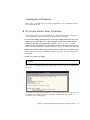
1. Determine that the drives are being recognized by the host by typing:
# ioscan -fnC disk
2. Start a System Administration Manager (sam) session.
3. Choose Disks and File Systems → Volume Groups.
4. From the Actions menu at the top of the window, click Create.
5. In the Create New Volume Group Name window, click Select New Volume Group
Name, type a name for the New Volume Group, and click OK.
6. In the Create New Volume Group window, click Select Disk(s), select the drive(s)
that are going to be in the Volume Group, and click OK.
7. In the Create New Volume Group window, click Define New Logical Volume(s).
a. In the LV name field, type a name for the logical volume.
b. Using the value displayed in the Approx Free Mbytes field, which specifies
Mbytes left in the volume group, determine the size of the new logical volume.
Although you can create multiple logical volumes, you must create at least one. If
you are creating one logical volume with the full capacity of the volume group,
type the number displayed in the Approx Free Mbytes field. If you are creating
multiple logical volumes, specify the size of each and type the size of the first
logical volume.
c. In the Mount Directory field, type the directory where you want to mount the
logical volume, and click Add.
d. To add more logical volumes, repeat Steps a-c.
e. When you have finished adding logical volumes, click OK.
8. In the Create New Volume Group window, click OK.
9. When you have finished creating logical volumes, close the Disk and File System
window and close sam.
34
Sun StorEdge 3000 Family Configuration Service 2.4 User’s Guide • March 2007
What to Do Next
Sun StorEdge Configuration Service is now installed, set up, and ready to use. See
the following chapters for additional tasks:
■
“Monitoring the Array” on page 75, for information about how to use Sun
StorEdge Configuration Service to monitor storage devices.
■
“Maintaining the Array” on page 127, for information about maintaining the
array. It includes detailed information about parity checking, scheduling parity
checks, rebuilding failed drives, and restoring a configuration from a backup file.
■
“Updating the Configuration” on page 149, when you want to update the
configuration of the storage array. It also covers changing controller features,
making or changing a standby drive, and editing the information for available
servers.
Chapter 3
Starting and Setting Up Sun StorEdge Configuration Service
35
36
Sun StorEdge 3000 Family Configuration Service 2.4 User’s Guide • March 2007
CHAPTER
4
Full Configuration
Sun preconfigures logical drives on the array before shipment. Read this chapter
only if the array is not already configured, or if you want to completely remove the
existing configuration and start again. If you want to make changes to the existing
configuration, see “Updating the Configuration” on page 149.
Full configuration includes the following topics:
■
■
■
“Configuring Logical Drives and Logical Volumes” on page 38
■
“To Use Standard Configuration” on page 39
■
“To Use Custom Configuration” on page 44
■
“To Create and Partition a Logical Volume” on page 57
■
“To Clear a Configuration” on page 59
■
“To Log Out of the Configuration Level” on page 60
“Host LUN Assignments” on page 60
■
“To Add or Change (Map) a Host LUN” on page 61
■
“To Delete (Unmap) a Host LUN” on page 62
“Configuration File” on page 62
■
“To Save a Configuration to a Backup File” on page 63
For the Sun StorEdge 3310 SCSI array or the Sun StorEdge 3320 SCSI array, if you are
planning to set up a cluster configuration, see “Using the Cluster Configuration
(SCSI Only)” on page 233.
The Configuration menu commands and toolbar icons might be temporarily
disabled if an array administration process, such as parity checking, is running. The
menu command is also deactivated when the console is refreshing its inventory on
the server. A satellite dish symbol is attached to the server icon during the refresh
process.
Caution – Back up any existing data to an external device before configuring the
array. Reconfiguration overwrites any existing logical drive configuration. When the
existing logical drive configuration is overwritten, all data is effectively erased.
37
Configuring Logical Drives and Logical
Volumes
The information contained in this section describes how to configure logical drives
and logical volumes using Standard or Custom Configuration.
Logical Drives
Depending on whether you want to use one or multiple RAID levels, logical drives
can be configured using Standard or Custom Configuration.
Logical Volumes
Logical volumes are created using Custom Configuration only. However, while the
ability to create and manage logical volumes remains a feature of Sun StorEdge
Configuration Service, the size and performance of physical and logical drives have
made the use of logical volumes obsolete. Logical volumes are unsuited to some
modern configurations such as Sun Cluster environments, and do not work in those
configurations. Avoid using them and use logical drives instead.
Maximum Number of Supported Logical Drives,
Logical Partitions, and LUN Assignments
The following table lists the maximum number of logical drives, partitions per
logical drive, number of partitions per logical volume, and maximum number of
LUN assignments for the Sun StorEdge 3310 SCSI array, Sun StorEdge 3320 SCSI
array, Sun StorEdge 3510 FC array, and the Sun StorEdge 3511 SATA array.
38
Sun StorEdge 3000 Family Configuration Service 2.4 User’s Guide • March 2007
TABLE 4-1
Maximum Number of Supported Logical and Physical Drives, Partitions, and LUN
Assignments
Array
Physical Drives
Logical
Drives
Partitions per
Logical Drive
Partitions per
Logical Volume
LUN Assignments
Sun StorEdge
3310 SCSI array
and Sun StorEdge
3320 SCSI array
36 (1 array and 2
expansion units)
16
32
32
128
Sun StorEdge
3510 FC array
108 (1 array and 8
expansion units)
32
32
32
128 (point-to-point mode)
64 (point-to-point mode,
redundant configuration)
1024 (loop mode)
512 (loop mode, redundant
configuration)
Sun StorEdge
3511 SATA array
72 (1 array and 5
expansion units)
32
32
32
128 (point-to-point mode)
64 (point-to-point mode,
redundant configuration)
1024 (loop mode)
512 (loop mode, redundant
configuration)
▼
To Use Standard Configuration
Use Standard Configuration Options to configure all of the storage attached to an
array controller using one RAID level. All you need to specify is the RAID controller,
optimization mode, RAID level, and whether you want a standby drive. Sun
StorEdge Configuration Service then automatically configures the storage for you,
creating one or more logical drives, depending on the RAID level and the number of
drives available. Write-back cache is selected by default. You are able to see the
resulting configuration and accept or reject it before it is completed.
Caution – Standard Configuration creates one large logical drive. In FC and SATA
configurations with large device capacities, the size of the logical drive might exceed
the device capacity limitation of your OS. Be sure to check the device capacity
limitation of your OS before using Standard Configuration.
Chapter 4
Full Configuration
39
Caution – Back up any existing data to an external device before using Standard
Configuration. Standard Configuration overwrites any existing logical drive
configuration. When the existing logical drive configuration is overwritten, all data
is effectively erased.
1. Log in as an ssconfig user.
2. Select the array that you want to configure.
3. Determine whether the optimization mode of the logical drive is to be Sequential
I/O (default) or Random I/O.
The optimization mode you select determines the maximum number of disks you
can include in an array and the maximum usable capacity of a logical drive, total
array capacity, and cache block size.
Optimization is set in the Cache tab of the Change Controller Parameters window
and is set to Sequential by default. For more information on Sequential I/O and
Random I/O, and for steps on how to change the optimization mode, see “Cache
Tab” on page 185.
4. Choose Configuration → Standard Configure.
A Standard Configuration Warning message is displayed. Click OK to continue.
40
Sun StorEdge 3000 Family Configuration Service 2.4 User’s Guide • March 2007
The Standard Configuration Options window is displayed. If you are not currently
logged in as ssconfig, a login dialog is displayed.
The options on the window might be disabled, depending on the number of drives
available and whether you have the Solaris OS or a Windows OS on the server.
Note – In FC and SATA configurations with large device capacities, the size of the
logical drive might exceed the device capacity limitation of your OS. Be sure to
check the device capacity limitation of your OS before using Standard Configuration.
The cluster configuration option creates a quorum RAID 5 logical drive (100 Mbyte)
and then allocates the remaining capacity over two large RAID 5 logical drives. For
this option, three or more physical drives are required.
5. Verify the server and the controller IDs displayed at the top of the window are
correct.
If the server and the controller displayed at the top of the window are not correct,
click Cancel to exit the configuration window and return to the main window. Select
the appropriate device and select the window again.
Chapter 4
Full Configuration
41
6. Indicate whether you want to use one of the drives as a standby drive.
When you select Use a standby drive, the program deactivates the RAID levels that
do not use standby drives. (For example, RAID 0 has no fault tolerance; therefore, a
standby drive provides no benefit.)
7. From the RAID levels made available, select the appropriate RAID level for the
logical drive you are configuring.
For definitions of the RAID levels, see “RAID Basics” on page 209.
You need a minimum of three drives to use RAID 3 or 5. If you select RAID 1, every
logical drive requires at least two physical drives. If you select four or more drives, a
logical drive with a RAID 1+0 is created.
8. (Solaris OS only). If you want the new logical drive to be automatically labeled,
which enables the OS to use the drive, click Write a new label to the new LD.
9. To use the logical drive immediately, select On-line Initialization.
Because logical drive initialization can take up to several hours, you can choose to
initialize a logical drive on-line.
On-line initialization enables you to begin configuring and using the logical drive
before initialization is complete. However, because the controller is building the
logical drive while performing I/O operations, initializing a logical drive on-line
requires more time than off-line initialization.
If you do not select On-line initialization, you can configure and use the drive only
after initialization is complete. Because the controller is building the logical drive
without having to also perform I/O operations, off-line initialization requires less
time than on-line initialization.
10. Select the stripe size.
Select a Default value to assign the stripe size per Optimization mode as specified in
TABLE 4-2, or select a different stripe size.
TABLE 4-2
Default Stripe Size Per Optimization Mode
RAID Level
Sequential I/O
Random I/O
0, 1, 5
128
32
3
16
4
Once the stripe size is selected and data is written to logical drives, the only way to
change the stripe size of an individual logical drive is to back up all its data to
another location, delete the logical drive, and create a logical drive with the stripe
size that you want.
42
Sun StorEdge 3000 Family Configuration Service 2.4 User’s Guide • March 2007
11. Specify Default, Write-through, or Write-back as the Write Policy for the logical
drive.
The write policy determines when cached data is written to the disk drives. The
ability to hold data in cache while it is being written to disk can increase storage
device speed during sequential reads. Write policy options include write-through
and write-back.
Using write-through cache, the controller writes the data to the disk drive before
signaling the host OS that the process is complete. Write-through cache has lower
write operation and throughput performance than write-back cache, but it is the
safer strategy, with minimum risk of data loss on power failure. Because a battery
module is installed, power is supplied to the data cached in memory and the data
can be written to disk when power is restored.
Using write-back cache, the controller receives the data to write to disk, stores it in
the memory buffer, and immediately sends the host OS a signal that the write
operation is complete, before the data is actually written to the disk drive. Writeback caching improves the performance of write operations and the throughput of
the controller card. Write-back cache is enabled by default.
Note – The setting you specify in the Write Back field on the Cache tab of the
Change Controller Parameters window is the default global cache setting for all
logical drives. (See “Cache Tab” on page 185.)
■
Default (Write -through or Write-back) – Assigns the global write policy that is
specified in the Write Back field of the Cache Tab on the Change Controller
Parameters window. If the global setting for write policy is changed,
automatically changes the write policy for this logical drive.
The array can be configured to dynamically switch write policy from write-back
cache to write-through cache if specified events occur. Write policy is only
automatically switched for logical drives with write policy configured to
“Default.” See “Peripheral Tab” on page 195 for more information about event
trigger operations.
■
Write-back – Assigns write-back cache regardless of any changes to the global
write policy.
■
Write-through – Assigns write-through cache regardless of any changes to the
global write policy.
12. Click OK.
The Confirm Configuration Operation window is displayed showing the new
configuration.
13. Click OK to accept the configuration as indicated; otherwise, click Cancel to
return to the console.
Chapter 4
Full Configuration
43
14. (HP-UX OS only). To ensure that the environment is stable and accurate after
making configuration changes, you need to run the ioscan -fnC disk command.
Note – If you used System Administrator Manager (sam) to unmount the file
system, make sure it is closed before running the ioscan command.
15. (IBM AIX OS only). To ensure that the environment is stable and accurate after
making configuration changes, you need to update the Object Data Manager
(ODM) as explained in “Updating the Object Data Manager on an IBM AIX Host”
on page 206.
Media Scan
A firmware menu option called Media Scan at Power-Up specifies whether media
scan runs automatically following a controller power-cycle, reset, or after logical
drive initialization. This setting is disabled by default. For more information, refer to
the Sun StorEdge 3000 Family RAID Firmware User’s Guide.
To determine whether or not media scan is running, see the event log. For more
information on the event log window, see “Event Log Window” on page 112. For
more information about media scan, see “To Scan Physical Disks for Bad Blocks
(Media Scan)” on page 132.
▼
To Use Custom Configuration
Custom Configuration gives you multiple choices for configuring or reconfiguring
logical drives with varying RAID levels. It also gives you the option of adding newly
created logical drives to logical volumes.
1. Log in as an ssconfig user.
2. Select the array that you want to configure.
3. Choose Configuration → Custom Configure.
44
Sun StorEdge 3000 Family Configuration Service 2.4 User’s Guide • March 2007
The Custom Configuration Options window is displayed.
■
New Configuration – Configures new logical drives with varying RAID levels
and other RAID parameters and enables you to add the new logical drives to
logical volumes. The New Configuration command erases the previous
configuration on an array controller.
■
Add LDs/LVs to the Current Configuration – Adds new logical drives/logical
volumes to an existing configuration. This command does not erase the other
configured logical drives on the controller.
■
Dynamically Grow and/or Reconfigure LDs/LVs – Enables you to expand the
capacity of logical drives and logical volumes, add drives to existing logical
drives and logical volumes, and copy and replace all member drives with drives
of higher capacity.
■
Make or Change Standby Drives – Adds one or more new standby drives to be
associated with the array controller.
■
Change Host LUN Assignments – Enables you to assign logical drives, logical
volumes, and partitions to a host channel.
Chapter 4
Full Configuration
45
■
Change Controller Parameters – Enables you to modify the controller parameters
■
Manage Existing LDs/LVs and Partitions – Enables you to delete individual
logical drives and logical volumes and create/delete partitions from existing
logical drives and logical volumes.
■
Configure Web Server (Sun StorEdge Enterprise Storage Manager Topology
Reporter software required) – Enables you to configure a web server so you can
manage/monitor an array through a web browser.
In this chapter, the New Configuration option is described in detail. Configure Web
Server is described in “Managing Storage Through the Web” on page 123. The
remaining options are described in “Updating the Configuration” on page 149.
The New Configuration Option
The New Configuration option enables you to customize the logical drive
configuration to meet the specific needs of your environment. You can configure and
partition one or more logical drives with varying RAID levels. You can then add two
or more logical drives (unpartitioned) to a logical volume and divide the logical
volume into a maximum of 32 partitions.
Note – On UNIX systems, if the console locks up during use, obtain the process
number, and then close and reopen the window as described in “If Console Locks
Up During Use” on page 11.
Before You Use New Configuration
Before you use New Configuration to create a logical drive or a logical volume for
the first time, it is useful to familiarize yourself with the information contained in
the following steps. Knowing this information ahead of time will ease the process of
creating a logical drive or volume.
Note – Logical volumes are unsuited to some modern configurations such as Sun
Cluster environments, and do not work in those configurations. Use logical drives
instead. For more information, see “Logical Volumes” on page 38.
1. If you have preconfigured logical drives that you want to delete, see “To Delete a
Logical Drive or Logical Volume” on page 157 for information, including how to
unmap assigned LUNs.
46
Sun StorEdge 3000 Family Configuration Service 2.4 User’s Guide • March 2007
Note – On preconfigured Sun StorEdge 3511 SATA arrays, you must first unmap
and delete logical drives so you can create new logical drives that support
redundancy.
2. Determine whether the optimization mode of the logical drive is to be Sequential
I/O (default) or Random I/O.
The optimization mode you select determines the maximum number of disks you
can include in an array and the maximum usable capacity of a logical drive, total
array capacity, and cache block size.
Optimization is set in the Cache tab of the Change Controller Parameters window
and is set to Sequential by default. For more information on Sequential I/O and
Random I/O, and for steps on how to change the optimization mode, see “Cache
Tab” on page 185.
3. Determine the total number of physical disks to be included in the logical drive,
which is dependent on the optimization mode selected.
If the security of your data is important, leave remaining disks for standby drives.
For information on the maximum number of disks and maximum usable capacity
per logical drive for random and sequential optimization, see “Maximum Number of
Disks and Maximum Usable Capacity for Random and Sequential Optimization” on
page 187.
Note – If the logical drive is going to be larger than 253 Gbyte, see “To Prepare for
Logical Drives Larger Than 253 Gbyte” on page 49.
4. Determine whether any standby (spare) drives are to be local or global.
A standby drive is a drive that is marked as a spare to support automatic data
rebuilding after a physical drive associated with a logical drive fails. For a standby
drive to take the place of another drive, it must be at least equal in size to the failed
drive. Also, the failed drive itself must be from a RAID 1, 3, or 5.
A local spare drive is a standby drive assigned to serve one specified logical drive.
When a member drive of this specified logical drive fails, the local spare drive
becomes a member drive and automatically starts to rebuild.
A global spare drive does not only serve one specified logical drive. When a member
drive from any of the logical drives fail, the global spare drive joins that logical drive
and automatically starts to rebuild. Global spares are used in the order in which they
are created.
5. Determine the RAID level; the program automatically computes the maximum
size logical drive that can be created at that RAID level.
6. Determine whether you want to partition the logical drive.
Chapter 4
Full Configuration
47
A partition is a division of the logical drive (or logical volume). Partitions enable you
to create the appearance of having separate logical drives (or logical volumes) for
file management, multiple users, or other purposes.
Note – Partitioning can be done during the initial configuration or after the logical
drive has been created.
Note – Logical drives that have more than one partition cannot be added to a logical
volume.
7. Understand the disk capacities displayed in the New Configuration window.
■
Max Drive Size (MB) – displays the maximum drive size per selected physical
disk (total capacity of each disk).
A smaller logical drive can be created by decreasing this value. The remainder can
be used later by expanding the drive (as explained in “To Expand the Capacity of
a Logical Drive or Logical Volume” on page 164).
■
Available Size (MB) – displays the total capacity of all disks, which is the total
logical drive or logical volume size.
Note – The maximum usable capacity for a logical drive is equal to the smallest
physical disk size. For example, if you add an 18-Gbyte disk and then add a 70Gbyte disk to be part of the logical drive, the maximum usable capacity is 18 Gbyte
per drive.
Note – Disk capacity is displayed in powers of 1024. See “Device Capacities” on
page 79 for specific capacity definitions.
8. Determine whether the logical drive is to be part of a logical volume.
Note – Logical volumes are unsuited to some modern configurations such as Sun
Cluster environments, and do not work in those configurations. Use logical drives
instead. For more information, see “Logical Volumes” on page 38.
Note – Logical drives that have more than one partition cannot be added to a logical
volume.
9. Determine whether you want to partition the logical volume.
48
Sun StorEdge 3000 Family Configuration Service 2.4 User’s Guide • March 2007
Note – Partitioning can be done during the initial configuration or after the logical
volume has been created.
▼ To Prepare for Logical Drives Larger Than 253 Gbyte
The Solaris OS requires drive geometry for various operations, including newfs. For
the appropriate drive geometry to be presented to the Solaris OS for logical drives
larger than 253 Gbyte, you have to configure Host Cylinder/Head/Sector Mapping
Configuration using the firmware application. Refer to the Sun StorEdge 3000 Family
RAID Firmware User’s Guide for your array for information about accessing the
firmware application.
1. In the firmware application, choose “view and edit Configuration parameters →
Host-Side Parameters → Host Cylinder/Head/Sector Mapping Configuration →
Sector Ranges - → Variable,” and then choose Yes to confirm your choice.
2. Choose Head Ranges and specify 64.
3. Choose Cylinder Ranges and specify Variable.
Note – Refer to your operating system documentation for limitations on device
sizes.
▼ To Create and Partition a Logical Drive Using New
Configuration
Before you create and partition a logical drive using New Configuration for the first
time, it is useful to review the steps under “Before You Use New Configuration” on
page 46.
The following steps provide a working example of how to create a new
configuration for a new logical drive. Three logical drives are selected and
configured into a RAID 5 logical drive. A small logical drive is then created and
partitioned.
Caution – Back up any existing data to an external device before using the New
Configuration command. Sun StorEdge Configuration Service automatically
initializes new logical drives defined on the array controller.
1. Log in as an ssconfig user.
2. Select the controller that you want to configure.
Chapter 4
Full Configuration
49
3. Make sure that you have selected the appropriate Optimization mode for your
application.
Optimization is set in the Cache tab of the Change Controller Parameters window
and is set to Sequential by default. For steps on how to change the Optimization
mode, see “Cache Tab” on page 185.
4. Choose Configuration → Custom Configure.
5. Click New Configuration.
A New Configuration Warning message is displayed.
6. Click OK.
7. Verify that the Server and Controller displayed at the top of the window are
correct.
If the server and the controller displayed are not correct, click Cancel to exit the New
Configuration window and return to the main window. Select the appropriate disk
controller and reselect New Configuration.
8. In the Select disks for Logical Drive list, select the first disk and click Add Disk.
Proceed to add the next two disks so that three disks are displayed in the lower list
box.
If you make a mistake or change your mind, select the drive from the drives list and
click Remove Disk.
Note – Because the logical drive has not been partitioned yet, the Part Size (MB) and
the Available Size (MB) are equal. A single logical drive is considered to be a single
partition.
Note – Mixing SATA and FC disks to create a logical drive is not supported.
50
Sun StorEdge 3000 Family Configuration Service 2.4 User’s Guide • March 2007
Max Drive Size – displays
the total capacity of each
disk
Available Size – displays
the total capacity of all
disks, which is the total
logical drive size
9. Select the RAID Level. For this example, select RAID Level 5.
This RAID level applies to all disks in this logical drive.
In this example, the new logical drive is composed of three physical disks, totaling
103428 Mbyte, as indicated in the Available Size (MB) field.
The maximum number of disks per logical drive for each RAID level for a 2U array
is:
■
■
■
■
RAID
RAID
RAID
RAID
0 - 36
1-2
1+0 - 36
3 or 5 - 31
For RAID 1, note that if you select four or more drives, a logical drive with a RAID
1+0 is created.
10. Set the Max Drive Size.
The Max Drive Size displays the total capacity of each disk. A smaller logical drive
can be created by decreasing this value.
Chapter 4
Full Configuration
51
Note – If you do not change the Max Drive Size but you change the Partition Size, a
new partition is created at the specified partition size. The remaining logical drive
size capacity moves to the last partition. If you do change the Max Drive Size, the
remaining capacity can be used later by expanding the drive (as explained in “To
Expand the Capacity of a Logical Drive or Logical Volume” on page 164).
11. From the Channel and ID list boxes, select the host channel and ID to which you
want the new logical drive mapped.
Host channels connect to host computers either directly or indirectly through
switches or other devices. Select the appropriate host channel based on the physical
connection from the server to the array.
The ID is a unique address that identifies the logical drive to the host.
Note – If you do not want to map the logical drive at this time, select Do Not Map
from the Channel list box.
12. To use the logical drive immediately, while it is building, select On-line
Initialization.
Because logical drive initialization can take up to several hours, you can choose to
initialize a logical drive on-line.
On-line initialization enables you to begin configuring and using the logical drive
before initialization is complete. However, because the controller is building the
logical drive while performing I/O operations, initializing a logical drive on-line
requires more time than off-line initialization.
If you do not select On-line initialization, you can configure and use the drive only
after initialization is complete. Because the controller is building the logical drive
without having to also perform I/O operations, off-line initialization requires less
time than on-line initialization.
Note – On-line Initialization does not apply to logical volumes.
52
Sun StorEdge 3000 Family Configuration Service 2.4 User’s Guide • March 2007
13. Select the Stripe Size.
Select Default to assign the stripe size per Optimization mode as specified in
TABLE 4-2, or select a different stripe size.
TABLE 4-3
Default Stripe Size Per Optimization Mode
RAID Level
Sequential I/O
Random I/O
0, 1, 5
128
32
3
16
4
Once the stripe size is selected and data is written to logical drives, the only way to
change the stripe size of an individual logical drive is to back up all its data to
another location, delete the logical drive, and create a logical drive with the stripe
size that you want.
Caution – Only change the stripe size after you have tested the effects on your
application.
14. Specify Default, Write-through, or Write-back as the Write Policy.
The write policy determines when cached data is written to the disk drives. The
ability to hold data in cache while it is being written to disk can increase storage
device speed during sequential reads. Write policy options include write-through
and write-back.
Using write-through cache, the controller writes the data to the disk drive before
signaling the host OS that the process is complete. Write-through cache has lower
write operation and throughput performance than write-back cache, but it is the
safer strategy, with minimum risk of data loss on power failure. Because a battery
module is installed, power is supplied to the data cached in memory and the data
can be written to disk when power is restored.
Using write-back cache, the controller receives the data to write to disk, stores it in
the memory buffer, and immediately sends the host OS a signal that the write
operation is complete, before the data is actually written to the disk drive. Writeback caching improves the performance of write operations and the throughput of
the controller card. Write-back cache is enabled by default.
Note – The setting you specify in the Write Back field on the Cache tab of the
Change Controller Parameters window is the default global cache setting for all
logical drives. (See “Cache Tab” on page 185.)
Chapter 4
Full Configuration
53
■
Default (Write-through or Write-back) – Assigns the global write policy that is
specified in the Write Back field of the Cache Tab on the Change Controller
Parameters window. If the global setting for write policy is changed,
automatically changes the write policy for this logical drive
The array can be configured to dynamically switch write policy from write-back
cache to write-through cache if specified events occur. Write policy is only
automatically switched for logical drives with write policy configured to
“Default.” See “Peripheral Tab” on page 195 for more information about event
trigger operations.
■
Write-back – Assigns write-back cache regardless of any changes to the global
write policy.
■
Write-through – Assigns write-through cache regardless of any changes to the
global write policy.
15. This step depends on what you want to do next:
■
To create another logical drive, click New LD and repeat Step 1 through Step 14.
■
To add this logical drive to a logical volume, click Add to LV and see “To Create
and Partition a Logical Volume” on page 57.
■
To partition this logical drive, continue with the following steps. In this example,
a small logical drive is created and partitioned.
■
If you are finished creating logical drives and do not want to add this logical
drive to a logical volume or partition it, click Commit.
16. To create a small logical drive, type 2000 in the Max Drive Size field.
Note – A total of 4000 Mbyte is shown for the logical drive size as opposed to 6000
Mbyte; because this is a RAID 5 level, you lose the capacity equal to 1 drive (2000
Mbyte) for parity.
54
Sun StorEdge 3000 Family Configuration Service 2.4 User’s Guide • March 2007
17. To create a partition, type 1000 in the Part Size field and click Add Partition.
Note – Do not partition a logical drive if you plan on adding it to a logical volume.
Once a logical drive is partitioned, it cannot be added to a logical volume.
To create multiple partitions of the same size, click Add Partition as many times as
partitions you want to create. You can also type the partition size in the Part Size
field and multiply (*) it by the number of partitions you want to create, for example
100*128. Any remaining Mbyte is added to the last partition.
As you add partitions, the remaining capacity displayed in Available Size (MB)
decreases by the amount of the partition size.
As shown in the following example, of the original 4000 Mbyte, 1000 Mbyte was
allocated to Partition 0. The remaining 3000 Mbyte is then automatically moved to
Partition 1. The remaining usable capacity is displayed in the Available Size (MB)
field.
Chapter 4
Full Configuration
55
18. (Solaris OS only). If you want the new logical drive to be automatically labeled,
which enables the OS to use the drive, click Write a new label to the new LD.
19. Click Commit to end the configuration of the logical drive or New LD to
configure another logical drive.
When you click New LD, any available disks that haven’t been used are displayed.
When the logical drive configuration for this array is complete, click Commit, and
then click OK. The completed configuration is displayed.
Note – You cannot change a logical drive configuration after you click OK.
Note – During initialization, LD/LV size is displayed as 0 Mbyte.
20. (HP-UX OS only). To ensure that the environment is stable and accurate after
making configuration changes, you need to run the ioscan -fnC disk command.
56
Sun StorEdge 3000 Family Configuration Service 2.4 User’s Guide • March 2007
Note – If you used System Administrator Manager (sam) to unmount the file
system, make sure it is closed before running the ioscan command.
21. (IBM AIX OS only). To ensure that the environment is stable and accurate after
making configuration changes, you need to update the Object Data Manager
(ODM) as explained in “Updating the Object Data Manager on an IBM AIX Host”
on page 206.
▼
To Create and Partition a Logical Volume
A logical volume is composed of two or more logical drives and can be divided into
a maximum of 32 partitions. During operation, the host sees a nonpartitioned logical
volume or a partition of a logical volume as one single physical drive.
Note – Logical volumes are unsuited to some modern configurations such as Sun
Cluster environments, and do not work in those configurations. Use logical drives
instead. For more information, see “Logical Volumes” on page 38.
1. Create a logical drive as described in Steps 1-11 in “To Create and Partition a
Logical Drive Using New Configuration” on page 49.
Note – Do not partition the logical drive that you are adding to the logical volume.
A logical drive that has been partitioned cannot be added to a logical volume.
2. Before you click Commit, to add the logical drive to a logical volume, click Add to
LV.
The logical drive is added to the LV Definition box. The total size of the logical
volume is displayed in the Available Size (MB) field.
Note – Because the logical volume has not been partitioned yet, the Part Size (MB)
and the Available Size (MB) are equal. A single logical volume is considered to be a
single partition.
Note – Mixing SATA and FC logical drives to create a logical volume is not
supported.
Chapter 4
Full Configuration
57
As logical drives are
added to the logical
volume, they are displayed
in the LV Definition box
Available Size – displays
the total capacity of all
disks, which is the total
logical volume size
3. To create another logical drive to add to the logical volume, click New LD.
4. Create the logical drive and add it to the logical volume by clicking Add to LV.
Repeat this step for every logical drive you want to add to the logical volume.
5. To create a partition, type the partition size in the Part Size field and click Add
Partition.
To create multiple partitions of the same size, click Add Partition as many times as
partitions you want to create. You can also type the partition size in the Part Size
field and multiply (*) it by the number of partitions you want to create, for example
100*128.
As you add partitions, the remaining capacity displayed in Available Size (MB)
decreases by the amount of the partition size.
6. When you have finished adding logical drives to the logical volume, to create
another logical volume or an individual logical drive, click Commit LV.
When you are finished creating logical volumes and do not want to create an
individual logical drive, click Commit.
58
Sun StorEdge 3000 Family Configuration Service 2.4 User’s Guide • March 2007
Note – When you have finished creating logical volumes and want to exit the New
Configuration window, if you accidentally click Commit LV instead of Commit, you
will have to create another logical drive; otherwise, you have to click Cancel and
configure the logical volume again.
To add or delete a logical volume to or partition a logical volume in an existing
configuration, see “Updating the Configuration” on page 149.
7. (HP-UX OS only). To ensure that the environment is stable and accurate after
making configuration changes, you need to run the ioscan -fnC disk command.
Note – If you used System Administrator Manager (sam) to unmount the file
system, make sure it is closed before running the ioscan command.
8. (IBM AIX OS only). To ensure that the environment is stable and accurate after
making configuration changes, you need to update the Object Data Manager
(ODM) as explained in “Updating the Object Data Manager on an IBM AIX Host”
on page 206.
Media Scan
A firmware menu option called Media Scan at Power-Up specifies whether media
scan runs automatically following a controller power-cycle, reset, or after logical
drive initialization. This setting is disabled by default. For more information, refer to
the Sun StorEdge 3000 Family RAID Firmware User’s Guide.
To determine whether or not media scan is running, see the event log. For more
information on the event log window, see “Event Log Window” on page 112. For
more information about media scan, see “To Scan Physical Disks for Bad Blocks
(Media Scan)” on page 132.
▼
To Clear a Configuration
If at any time during the configuration process in the New Configuration window
you are dissatisfied with the configuration, you can clear it.
1. Click Clear to remove all physical and logical drives from the display.
2. Either click New LD to define a new logical drive, or click Commit.
3. When you click Commit, a warning prompt is displayed; click OK.
Sun StorEdge Configuration Service initializes the entire configuration on the
selected array controller.
Chapter 4
Full Configuration
59
Note – Host LUNs are automatically mapped after logical drives have completed
the initialization process.
▼
To Log Out of the Configuration Level
When you have finished with configuration activities, log back in to the monitoring
level of the program.
1. Choose File → Logout.
2. Select Logout to monitoring mode and click OK.
Host LUN Assignments
For the server to recognize a logical drive/logical volume, it must first be mapped to
a host channel/ID. When a logical drive/logical volume is mapped to a host
channel/ID, it becomes a logical unit number (LUN). The following section
describes how to map a logical drive/logical volume to a host channel and how to
remove it.
Note – When logical drives/logical volumes are first created, unless Do Not Map is
selected, the host LUNs are automatically mapped after logical drives/logical
volumes have completed the initialization process.
Note – Sun StorEdge 3310 SCSI arrays and Sun StorEdge 3320 SCSI arrays support
a maximum of 128 LUN assignments. Sun StorEdge 3510 FC arrays and Sun
StorEdge 3511 SATA arrays support a maximum of 1024 LUN assignments
(maximum number of LUNs assigned to each host ID is 32).
Note – Some versions of operating system software or utilities might not display all
mapped LUNs if there is no partition or logical drive mapped to LUN 0. Map a
partition or logical drive to LUN 0 if you are in doubt, or refer to your operating
system documentation.
60
Sun StorEdge 3000 Family Configuration Service 2.4 User’s Guide • March 2007
▼
To Add or Change (Map) a Host LUN
1. Choose Configuration → Custom Configure.
2. Select Change Host LUN Assignments.
The Change Host LUN Assignments window is displayed.
3. From the Select Host Channel and SCSI ID list box, select the channel and ID to
which the LUN is to be assigned.
All available logical drives are displayed under Partitions. For your reference, Used
LUNs displays a list of LUNs used for a specified channel and Partition Assignment
displays a list of channels, IDs, and LUNs to which a partition has been assigned.
4. Select the partition you want to map, and click Assign Host LUN.
To map multiple partitions (up to 32), select the first partition, scroll to the last
partition and Shift-click to select everything in between. Then click Assign Host
LUN. As a result, Unmap Host LUN becomes active.
5. When finished, click OK to save your changes and to return to the main menu.
Note – In the event that an error message is displayed when mapping a host
channel, repeat Steps 1 through 5.
Chapter 4
Full Configuration
61
▼
To Delete (Unmap) a Host LUN
1. With the Change Host LUN Assignments window displayed, select the LUN to be
deleted from the Host LUN Assignments field.
2. Click Unmap Host LUN.
3. When finished, click OK to save your changes and to return to the main menu.
Configuration File
Keep a backup copy of the current configuration on diskette or on an external device
other than the array. Even though configuration information is stored on array
controllers and on the physical drives attached to them, circumstances such as a fire
or a flood can occur, causing damage to both the controller and the drives. A backup
copy of the configuration enables you to restore the configuration to a new controller
without having to completely reconfigure the storage array.
Always save the array controller configuration to a file whenever you:
62
■
Install a new storage system enclosure or change the ID for the controller in an
existing enclosure
■
Replace a controller
■
Reconfigure or add logical drives to a controller
■
Rebuild the data from a failed drive to a standby drive
Sun StorEdge 3000 Family Configuration Service 2.4 User’s Guide • March 2007
▼
To Save a Configuration to a Backup File
1. Select the controller with the configuration you want to save.
2. Choose Configuration → Save Configuration.
The Save Configuration window is displayed.
3. If necessary, navigate to the drive and folder where you want the configuration
file to be saved.
Save the file to a diskette or a drive external to the array.
4. Specify the configuration file name and click Save.
The Save Configuration window is displayed.
5. Type a description of the configuration you are saving.
6. Click OK.
The controller configuration information is saved to a .cfg file.
Chapter 4
Full Configuration
63
Loading the Configuration
If a drive or controller is damaged and needs to be replaced, see “To Restore a
Logical Drive Configuration” on page 140, which describes how to load a
configuration file and restore a logical drive configuration.
64
Sun StorEdge 3000 Family Configuration Service 2.4 User’s Guide • March 2007
CHAPTER
5
LUN Filtering (FC and SATA Only)
This chapter explains how to create a LUN filter for the Sun StorEdge 3510 Fibre
Channel array and the Sun StorEdge 3511 SATA array to maintain large Fibre
Channel networks that share common storage. Topics covered in this chapter
include:
■
■
“Overview” on page 65
“Assigning a LUN Filter” on page 67
■
“To Access the LUN Filter View” on page 67
■
“To Add a New Host Manually” on page 67
■
“To Add an HBA Device Manually” on page 69
■
“To Remove Standard Host Mapping” on page 71
■
“To Assign a LUN Filter” on page 72
■
“To Delete a LUN Filter” on page 74
Overview
An important part of effectively maintaining a storage infrastructure depends on
how accessible and secure the data is at all times. With LUN filtering support, Sun
StorEdge Configuration Service provides a utility for secure centralized storage
access management.
For multiple servers connected to the same FC array, LUN filtering provides a
proprietary path from a host (server) to a logical drive and essentially hides or
excludes the other connected servers from seeing or accessing the same logical drive.
That is, the LUN filter organizes how the FC array devices are accessed and viewed
from host devices, and typically maps a FC array device to only one host so that
other hosts do not access and use the same FC array device.
65
LUN filtering also enables multiple logical drives to be mapped to the same LUN,
enabling different servers to have their own LUN 0 to boot from, if needed. LUN
filtering is also valuable in clarifying mapping when each host bus adapter (HBA)
typically sees twice the number of logical drives when viewed through a hub.
Each Fibre Channel device is assigned a unique identifier called a worldwide name
(WWN). A WWN is assigned by the IEEE and is similar to a MAC address in IP or a
URL on the Internet. These WWNs stay with the device for its lifetime. LUN filtering
uses this WWN to specify which server is to have exclusive use of a specific logical
drive. From the main menu of the console, an easy drag-and-drop method is used to
map each logical drive to a host’s Fibre Channel HBA card, identified with a WWN.
In the following example, when you map logical drive (LUN 01) to host channel 0
and select WWN1, server A has a proprietary path to that logical drive. With LUN
filtering, the logical drive is visible and accessible to only the HBA device on the
host, but not to any other HBA device. All three servers continue to see and access
LUN 02 and LUN 03 unless filters are assigned to them.
Server B
WWN2
Server A
WWN1
Server C
WWN3
C
LUN 01
FIGURE 5-1
LUN 02
LUN 03
Example of LUN Filtering
An advantage of LUN filtering is that it enables many more hosts, with multiple
OSs, to attach to an array through a common Fibre Channel port and still maintain
LUN security.
66
Sun StorEdge 3000 Family Configuration Service 2.4 User’s Guide • March 2007
Assigning a LUN Filter
Assigning a LUN filter involves the following steps:
■
■
■
■
■
▼
Accessing the LUN Filter View
Adding a new host manually (if you do not see the desired host)
Adding an HBA device manually (if you do not see the desired HBA)
Removing standard mapping
Assigning the LUN filter
To Access the LUN Filter View
1. From the main window, click the Filter View tab.
2. Click the container symbol
to expand the device trees for detailed views of the
servers (hosts) in the left pane and the array devices in the right pane.
▼
To Add a New Host Manually
If you do not see the desired host displayed in the left pane (under Hosts), add it
manually through the Configure Host/WWN window.
1. From the main window, click the Filter View tab.
2. Choose Configuration → Configure Host/WWN.
Note – If the Configure Host/WWN option is not enabled, select any one of icons in
the left pane to enable it.
Chapter 5
LUN Filtering (FC and SATA Only)
67
3. If are not already logged in as ssconfig or ssadmin, a password prompt is
displayed. Type the password and click OK.
The Configure Host/WWN window is displayed.
4. Under Available Hosts, look for the host.
■
If you see the host, go to Step 9.
■
If you do not see the host, continue with Step 5.
5. Under the Available Hosts pane, click Add.
The Add/Edit Host window is displayed.
6. Enter the host name, IP address, and the OS, and then click Add.
The Add/Edit HBA window is displayed.
7. Enter the adapter name and the appropriate WWN, and then click OK.
For details on determining the WWN, see “Determining Host Worldwide Names
(Fibre Channel and SATA Only)” on page 239.
8. Click OK to close the Add/Edit Host window.
9. Under Available Hosts, select the host, and click Add to add the host to the
Connected Hosts list.
10. Click OK to close the Configure Host/WWN window.
A confirmation message is displayed.
11. Click Close.
When you return to the Filter View tab, the new host is available for LUN filtering.
68
Sun StorEdge 3000 Family Configuration Service 2.4 User’s Guide • March 2007
12. (Optional) If you want to map multiple hosts to an array, select Configuration →
LUN Filter Properties, and then choose the array from the Select Sun StorEdge
3000 Family System list box.
Select the Hardware Filter and Map to Multiple Hosts check boxes, and then click
OK.
Note – If you deselect the Hardware Filter check box, you cannot assign LUN filter
mapping; you can only assign a standard map.
▼
To Add an HBA Device Manually
If you do not see the desired HBA device displayed in the left pane (under Hosts),
add it manually through the Configure Host/WWN window. You can add up to 64
WWNs per array.
1. Choose Configuration → Configure Host/WWN.
Note – If the Configure Host/WWN option is not enabled, select any one of icons in
the left pane to enable it.
2. If are not already logged in as ssconfig or ssadmin, a password prompt is
displayed. Type the password, and click OK.
The Configure Host/WWN window is displayed.
3. Under Connected Hosts, select the host that you want to add an HBA device to,
and click Remove.
Chapter 5
LUN Filtering (FC and SATA Only)
69
4. Under Available Hosts, select the host, and click Edit.
The Add/Edit Host window is displayed.
5. Click Add.
The Add/Edit HBA window is displayed.
6. Enter the new Adapter Name and the appropriate WWN, and click OK.
For details on determining the WWN, see “Determining Host Worldwide Names
(Fibre Channel and SATA Only)” on page 239.
7. Click OK to close the Add/Edit Host window.
8. Under Available Hosts, select the host, and click Add to move the host back to the
Connected Hosts list.
9. Click OK to close the Configure Host/WWN window.
A confirmation message is displayed.
70
Sun StorEdge 3000 Family Configuration Service 2.4 User’s Guide • March 2007
10. Click Close.
When you return to the LUN Filter view, the new HBA device is gray. It is available
for LUN filtering.
▼
To Remove Standard Host Mapping
Before you can assign a LUN filter, you have to remove the standard host mapping,
(indicated by an M label
), from the array. Standard mapping enables all hosts to
see all standard mapped logical drives. LUN filtering restricts the mapping to
specific host(s).
1. From the main window, click the Filter View tab.
2. From the right pane, click each All Hosts item, and drag and drop it to Storage
Pools.
3. Click Yes to the warning message.
A confirmation message is displayed.
4. Click Close.
When you return to the Filter View tab, note that the M label
from the logical drive.
Chapter 5
has been removed
LUN Filtering (FC and SATA Only)
71
▼
To Assign a LUN Filter
After you remove the standard mapping, you are ready to assign a LUN filter by
mapping logical drives to hosts.
1. From the main window, click the Filter View tab.
2. Select a logical drive under Storage Pools, and drag and drop it to the appropriate
HBA device (
) under Hosts.
A warning message is displayed.
Note – If the HBA device connected to the array is not known, drag and drop the
logical drive to the host (server) in the left pane. The program prompts you to filter
the array for each HBA device in the host. When this happens, the logical drive is
visible to the HBA device on the host, but it is not visible (or accessible) to any other
HBA device.
3. Click Yes.
The Specify Map Information window is displayed. Note that the program
automatically maps the logical drive to the first HBA device listed in the host if there
is more than one HBA device.
4. Assign the logical drive to a primary or secondary controller with the desired
channels and LUN ID numbers, and then click OK.
A confirmation message is displayed.
5. Click Close.
The assignment of the primary controller or secondary controller to an HBA card is
selected for the initial LUN filter assignment, and cannot be changed unless you
delete the LUN filter assignment and start over.
To apply a LUN filter to a second host for one array, repeat the steps in “To Add an
HBA Device Manually” on page 69 and “To Assign a LUN Filter” on page 72.
In the following example, the Sun StorEdge 3510 Fibre Channel device has LUN
filters (note the letter F for filter) to two separate hosts.
72
Sun StorEdge 3000 Family Configuration Service 2.4 User’s Guide • March 2007
Caution – Because data corruption can occur, a warning message is displayed if
two users access the same logical drive at the same time. This is a characteristic of
some host operating systems. Click Yes to add the additional host.
Chapter 5
LUN Filtering (FC and SATA Only)
73
▼
To Delete a LUN Filter
1. From the main window, click the Filter View tab.
2. From the right pane, select the associated WWN, and drag and drop it to Storage
Pools.
A warning message is displayed.
3. Click Yes.
A confirmation message is displayed.
4. Click Close.
74
Sun StorEdge 3000 Family Configuration Service 2.4 User’s Guide • March 2007
CHAPTER
6
Monitoring the Array
This chapter explains how to monitor the array using Sun StorEdge Configuration
Service. It describes the main window and the component view windows that are
available when an icon is double-clicked in the main window. It also explains how
the Event Log works and how to use the reporting function. It is organized into the
following sections:
■
■
■
■
■
■
■
“The Main Window” on page 76
“Viewing Detailed Device Information” on page 83
“Event Log” on page 109
“Save Report” on page 114
“View Report” on page 117
“In-Band and Out-of-Band Storage Management” on page 117
“Managing Storage Through the Web” on page 123
Note – Sun StorEdge Configuration Service can monitor and manage up to 32
arrays at one time. However, console response time can decrease as the number of
arrays increases.
75
The Main Window
The main window provides status at a glance for all array devices. It indicates the
status of the devices and logical drives connected to servers monitored by the
console. The devices include array controllers, disk storage enclosures, physical disk
drives, and other SCSI devices.
This window’s tree structure offers detail for all devices connected to each server.
The
or
container symbol at the left side of the tree indicates whether the
display of devices is expanded or collapsed. The
container symbol means that
you can click to display more devices. The
container symbol indicates that all
devices at and below that level are shown.
The following figure shows an example of the expanded view of the main window.
See “To Verify Storage Configurations” on page 27 for a description of typical device
icons displayed for a configured array.
Note – The SN# represents the unique ID of the array.
76
Sun StorEdge 3000 Family Configuration Service 2.4 User’s Guide • March 2007
The following figure shows an example of a collapsed view.
For more information, you can double-click an icon to open a component view
window. The component views are covered later in this chapter.
Device Status
Another feature of the main window is that device status is color-coded and symbolcoded so that it is easy to identify when a device is in a state that requires attention.
The status is propagated along the device tree, enabling you to trace a failure down
to the device level. See TABLE 6-1 for device status color and symbol descriptions.
TABLE 6-1
Device Color and Symbol Status
Color
Symbol
Status
Purple
None
The group, server, or device is online.
White
None
The user has not logged into this server.
Yellow
One or more components of this group or server are not
working, but the array is still functional. See “Degraded State”
on page 78 for further details.
Red
One or more components of this group or server are not
working, which has placed the device in a critical state. See
“Critical State” on page 78 for further details.
Chapter 6
Monitoring the Array
77
Degraded State
Reasons for which a device might be placed in a degraded state include but are not
limited to the following:
■
Depending on the size of the logical drive and the number of physical drives it
contains, a logical drive that has one or more failed physical drives can be
operating in a degraded state. See “View Logical Drive” on page 93 to determine
the status of the logical drive and the status of the physical drives that make up
the logical drive.
■
If one or more of the environmental components, including the power supplies,
fans, and temperature is not working, but the array is still functional, the
enclosure, array, and server icons indicate a degraded state. See “View Enclosure”
on page 95 for more information.
■
If the controller shuts down because the option to shut down the controller if the
temperature exceeds the threshold limits has been enabled, the controller is
operating in a degraded state. See “Peripheral Tab” on page 195 for more
information.
■
For the Sun StorEdge 3510 FC array or Sun StorEdge 3511 SATA array, a degraded
state might indicate that the battery is going to expire in 21 days, or that the inservice date has not been set for a replacement battery. See “Battery Information”
on page 103 for general battery information, and see “To Verify the In-Service
Date When Replacing a Battery” on page 105 for information about the in-service
date. Refer to the Sun StorEdge 3000 Family FRU Installation Guide for details on
installing a replacement battery.
Critical State
Reasons for which a device might be placed in a critical state include but are not
limited to the following:
78
■
Depending on the size of the logical drive and the number of physical drives it
contains, a logical drive that has one or more failed physical drives can be
operating in a critical state. See “View Logical Drive” on page 93 to determine the
status of the logical drive and the status of the physical drives that make up the
logical drive.
■
If two or more of the environmental components, including power supplies, fans,
and temperature is not working, for example, three fans fail or two power
supplies fail, the enclosure, array, and server icons indicate a critical state. See
“View Enclosure” on page 95 for more information.
■
If a controller device exceeds or does not meet the threshold range that was set
using the firmware application, the controller icon indicates a critical state. See
“To View Environmental Status for the Controller” on page 197 for more
information.
Sun StorEdge 3000 Family Configuration Service 2.4 User’s Guide • March 2007
■
For the Sun StorEdge 3510 FC array or Sun StorEdge 3511 SATA array, a degraded
state might indicate that the battery has expired. See “Battery Information” on
page 103 for more information about the battery.
Device Capacities
Sun StorEdge Configuration Service windows often present the capacity of devices
such as logical drives. All device capacity is displayed in powers of 1024.
■
■
■
■
1
1
1
1
Kbyte = 1024 bytes
Mbyte = 1024 Kbyte = 1,048,576 bytes
Gbyte = 1024 Mbyte = 1,073,741,824 bytes
Tbyte = 1024 Gbyte = 1,099,511,627,776 bytes
Online Help
To access online help, choose Help → Contents. The online help is in HTML format
and depending on the OS, can be run through Microsoft Internet Explorer or
Netscape Navigator™. It includes information about major functions within the
program.
Tree View of Product Configurations
For each server (or group of servers), devices in the tree view are arranged in a
hierarchical order with the server (or group) at the top, followed by the array
controllers. How the remaining devices — logical drives, physical drives, and
enclosures — are shown might vary slightly, depending on which array and
controller are being displayed. This section provides window views that might be
depicted in the tree view.
Groups
A group is a logical collection of servers within the device tree. This new data object
enables multiple servers to be contained under a single category.
The group object
looks and behaves like all tree objects. It has an iconic
representation and generally assumes the status of its servers. The following figure
shows the group icon expanded to show the subordinate or underlying server
objects.
Chapter 6
Monitoring the Array
79
A group is a new data object that enables multiple servers to be contained under a
single category. Groups are similar in concept to domains. They enable you to
organize servers. Instead of a linear tree of all the managed servers, you can
organize the servers into like sets or groups.
Groups are color-coded and symbol-coded similarly to servers. States with their
corresponding colors have the following order of precedence:
■
■
■
■
■
Critical – Red (the highest)
Nonresponding – Gray
Degraded – Yellow
Optimal – Purple
Not logged into – White
A server icon assumes the color of the highest state of any of its storage system.
Likewise, a group icon takes on the highest state of any of its servers, with the
following exceptions involving non responding or unlogged servers.
When a group icon is disabled (inactive), it indicates that all the servers attached to
that group are not responding; if any number less than all of the servers in the group
is not responding, the group icon appears red, representing a critical state. For
example, if there are four servers in the group and three or fewer servers are not
responding, the group icon is color-coded red.
80
Sun StorEdge 3000 Family Configuration Service 2.4 User’s Guide • March 2007
When a group icon is color-coded white (not logged in), it indicates that one or more
servers within that group have not yet been fully configured, or could represent a
period of status transition. TABLE 6-2 gives an example of the different color coding of
a two-server group.
TABLE 6-2
Two-Server Group Colors
Server 1
Icon Color
Server 2
Icon Color
Group Icon Color
Gray
Gray
Gray
Yellow, Red, Purple, or White
Gray (not responding)
Red (critical)
White
White
White (not logged into)
White
Yellow
Yellow (degraded)
White
Red
Red (critical)
White
Red
Purple
Any Color
Purple (optimal)
Red (critical)
Yellow
Purple
Yellow or Purple
Purple
Yellow (degraded)
Purple (optimal)
Groups are not required. You can configure the program for no groups and fifteen
servers, for example, or for one group with ten servers underneath, with an
additional five at the top level. The program enables any combination.
The number of groups permitted and the number of servers within a group is
limited only by available system memory. If a server is a member of a group and a
user deletes that group from the group list box, servers are reassigned in that group
to the no group category. The tree is remapped in the main window.
The Monitoring Process
The console monitors storage devices on a network by communicating with an agent
on the servers.
When the program is started, the console software begins by establishing contact
with the agent on each managed server if Auto Discovery was specified when the
server was configured. If Auto Discovery was not specified, you have to double-click
each server and provide a password to start the discovery process for that server.
Establishing a TCP/IP connection between the console and the agent on each server
and receiving back inventory information can take several minutes, depending on
the complexity of the network. When this is occurring, the server icon in the main
window displays a satellite dish icon on its right side. Once the inventory is
refreshed, the satellite dish symbol is replaced by an active server symbol.
Chapter 6
Monitoring the Array
81
The agent on each server does a periodic scan of its inventory to check for changes.
If there is a change, the agent sends an event to the console. Depending on the event,
the console might request the inventory from that server’s last scan to use for
updating the representation of the server as displayed on the main window. During
this process, the satellite dish icon is attached to the server icon, and you cannot do
any configuration and array activity commands on that server until the refresh
process is completed and the console main window is updated.
When the program is running and the server agent and console are connected, the
agent pings or transmits a periodic signal to the console to verify the server’s status.
If the console does not receive a certain number of consecutive responses
(handshakes) from the agent, the console marks the server as offline and disconnects
from the server. The server’s icon is made inactive and adjacently marked with a
question mark symbol.
If a nonactive server was originally made active through the Auto Discovery
function, the console periodically tries to reestablish server communications.
Occasionally, you might want to have an inventory performed on a server between
the periodic status scans. To do this, double-click the server’s icon to display the
Server View window, and then click Rescan in that window.
Auto Discovery Options
If you have selected the Auto Discovery option (during the process of adding servers
to the Managed Servers list, see “Select or Deselect Automatic Discovery of servers:”
on page 14), the program automatically scans and performs an inventory on these
servers. You are not required to provide a monitoring password to retrieve
information provided by the program. Depending on the complexity of the network
and the number of servers, it can take several minutes for the discovery process to
finish.
However, if you choose not to use the Auto Discovery option on startup, the servers’
icons are white, indicating that there is currently no information available for these
servers. In this case, you need to double-click each server icon and specify the
appropriate monitoring password.
You can also choose File → Login. Once the password is specified for a server, the
discovery process begins to perform an inventory on the selected server.
Note – If you need a very secure environment where access to server inventory data
is restricted, select No for Auto Discovery (see “Select or Deselect Automatic
Discovery of servers:” on page 14).
82
Sun StorEdge 3000 Family Configuration Service 2.4 User’s Guide • March 2007
Viewing Detailed Device Information
Sun StorEdge Configuration Service provides detailed information about each agent
or server and about the array devices that are connected to it. The fields on each of
these views vary, depending on the capabilities of the disk controller.
Except for Save Report and View Report, which are located under the File menu, the
commands and windows described in this section are accessed through the View
menu.
■
■
■
■
■
■
■
■
■
■
■
■
View Group
View Server
View HBA Card
View Controller
View Logical Drive
View Physical Drive
View Enclosure
View FRU
Array Administration Progress
Agent Options Management
Save Report
View Report
View Group
View Group displays the servers that make up the group that is selected in the main
window.
To access View Group, double-click the group icon
select the group icon and choose View → View Group.
in the main window or
The Server List displays all servers that are attached to the specified group.
Chapter 6
Monitoring the Array
83
To view more information about any of the servers listed, select the appropriate
status record in the list and click View, or double-click the status record. A window
describing the corresponding server is displayed.
View Server
View Server displays the characteristics of the server that is selected in the main
window.
To access View Server, double-click the server icon
the server icon and choose View → View Server.
84
in the main window or select
Sun StorEdge 3000 Family Configuration Service 2.4 User’s Guide • March 2007
Part of the TCP/IP network, the socket port makes a connection between the server
and the client.
■
Connection List – Displays host adapters and array controllers that are installed
in or connected to the specified server.
Note – Dual-port HBAs are displayed as separate entries because they have
separate channels to which devices can be connected.
■
Rescan – Sends a command to the selected server to rescan existing inventory and
refresh the console. Normally, each managed server performs a periodic scan of
its inventory and updates the console if there is a change. If you want to perform
a diagnostic of all assigned devices, click Rescan; selecting this button essentially
circumvents the periodic and automatic status updates.
■
Probe – Sends a command to the selected server to probe for new inventory (for
example, RAID controllers, JBODs, and expansion units). Whenever a new device
has been added, or a device name has changed and you want it to be displayed in
the main window tree view immediately, click Probe.
Chapter 6
Monitoring the Array
85
View HBA Card
View HBA Card displays the characteristics of the host bus adapter (HBA) card that
is selected in the main Sun StorEdge Configuration Service window. It is only
displayed when using out-of-band management.
To access View HBA Card, double-click the host adapter icon
in the main Sun
StorEdge Configuration Service window or select the HBA icon and select View →
View HBA Card.
View HBA Card displays the status of the host adapter card and its device driver and
provides a list of the devices connected to the adapter. Sun StorEdge Configuration Service
channels start with number 0. The server listed at the top of the window is the server in
which the HBA is installed.
86
Sun StorEdge 3000 Family Configuration Service 2.4 User’s Guide • March 2007
View Controller
View Controller displays the components that make up the array.
To access View Controller, double-click the array icon
in the main window, or
select it and choose View → View Controller. The View Controller Configuration
window is displayed.
The tabs at the bottom section of the window provide detailed information about the
RAID controller’s LUNs, on the physical drives attached to it, on the enclosure
where the controller is located, and on the configuration of the peripherals. To bring
the information for another tab into view, click the tab.
Chapter 6
Monitoring the Array
87
Controllers Tab
To access this window, double-click the array icon
in the main window, or
select it and choose View → View Controller. Then click the Controller tab.
The Controller tab lists the controllers. To view more information about the
controllers, double-click the controller or select the controller and click View.
Depending on whether the controller is primary or secondary, the View Primary or
View Secondary Controller Configuration window is displayed. See “View
Primary/Secondary Controller Configuration” on page 90.
Physical Drives Tab
To access this window, double-click the array icon
in the main window, or
select it and choose View → View Controller, and then click the Physical Drives tab.
The following example shows the View Controller Configuration window with the
Physical Drives tab displayed.
View FRU is not
displayed for the
Sun StorEdge 3510
Fibre Channel array.
Scan SCSI Drive
is not displayed
for the Sun StorEdge
3510 Fibre Channel
array.
The Physical Drives tab lists the physical drives associated with the array. To see
details about any of the physical drives listed, double-click the drive or select the
drive and click View. The View Physical Drive window is displayed. For more
information about View Physical Drive, see “View Physical Drive” on page 94.
88
Sun StorEdge 3000 Family Configuration Service 2.4 User’s Guide • March 2007
Scan SCSI Drive
For the Sun StorEdge 3310 SCSI array and the Sun StorEdge 3320 SCSI array, if a
drive fails, the Scan SCSI Drive button is displayed. A SCSI hard drive can be
scanned in and made available without having to shut down the array.
Identify Drive On
To identify a single physical drive, for example, if you are receiving errors on a
specific channel ID and you need to determine which drive is causing the errors,
select the drive from the list, and click Identify Drive On. The selected drive’s LED
changes to amber, and the button toggles to Identify Drive Off. Click Identify Drive
Off to change the drive’s LED back to green.
Enclosure Info Tab
To access this window, either double-click the enclosure icon
in the main
window, or select the array icon
and choose View → View Controller. Select the
Enclosure Info tab. Select an enclosure and click View.
The information in the Enclosure Info tab includes the status of the power supplies,
fans, battery, and the enclosure temperature. For more information about View
Enclosure, see “View Enclosure” on page 95.
View FRU
For the Sun StorEdge 3310 SCSI array only, to display the field-replaceable unit
identification (FRU ID) information for the array, click View FRU. For example FRU
ID information, see “View FRU” on page 107.
Chapter 6
Monitoring the Array
89
View Controller Parameters
Click View Controller Parameters to view detailed information about channels, RS
232, cache, disk array, drive I/F, host I/F, redundancy, peripheral devices, network
parameters, and supported protocols. To view the information, click the tab that
corresponds to the item you want to view. To change controller parameters, see “To
Change Controller Parameters” on page 179.
Channel Parameters
Each controller has an RS-232 port and an Ethernet port. This architecture ensures
continuous communication should one controller fail. Since the communication is
established to only one controller at a time (even when the array is in redundant
mode), the CurClk and CurWid parameters are displayed for the primary controller.
Therefore, if a user maps one LUN to the primary controller and another LUN to a
secondary controller, only the established connection to the primary controller is
displayed through the serial and Ethernet port menu. As a result, if a primary ID is
not mapped to a channel, and a secondary ID is mapped, “Async” is displayed in
the CurClk field.
View Primary/Secondary Controller Configuration
View Primary and View Secondary Controller Configuration windows display the
characteristics of the controller that is selected in the main window. To display the
primary controller characteristics, select the primary controller from the main
window and choose View → View Controller, or double-click the primary controller.
90
Sun StorEdge 3000 Family Configuration Service 2.4 User’s Guide • March 2007
The following two examples show the primary controller.
View FRU is not
displayed for the
Sun StorEdge 3510
Fibre Channel array.
Chapter 6
Monitoring the Array
91
The following two examples show the secondary controller.
View FRU is not
displayed for the
Sun StorEdge 3510
Fibre Channel array.
92
Sun StorEdge 3000 Family Configuration Service 2.4 User’s Guide • March 2007
View Logical Drive
View Logical Drive displays the characteristics of the logical drive that is selected in
the main window.
To access this view window, use one of the following methods.
■
Double-click the logical drive icon
in the main window.
■
Select the logical drive icon and choose View → View Logical Drive.
For more information about any of the disk drives listed, either double-click the
drive’s status record, or select the drive and click View. The View Physical Drive
window is displayed.
Chapter 6
Monitoring the Array
93
View Physical Drive
View → View Physical Drive presents the characteristics of the selected physical
drive. You can access it by double-clicking the physical device
in the main
window, or by selecting the device and choosing View → View Physical Drive.
Node Name WWN and
Alternate I/O Path are
not displayed for the
Sun StorEdge 3310
SCSI array or the Sun
StorEdge 3320 SCSI
array.
94
■
Remaining Size – Remaining unused capacity when part of a physical drive’s
capacity has been used in one or more logical drives.
■
RPM – The revolutions per minute of the physical drive
■
SMART Drive – Indicates whether the drive has predictive failure capability
■
Node Name WWN (FC and SATA only) – Uniquely identifies the physical drive
■
Alternate I/O Path (FC and SATA only) – Reports the status of the available paths
between the controller and the physical drives. A status of Active for both drives
indicates that there is a redundant path between the controller and the physical
drives.
Sun StorEdge 3000 Family Configuration Service 2.4 User’s Guide • March 2007
View Enclosure
The View Enclosure window displays the component and alarm characteristics of an
enclosure that is selected in the main window. For the Sun StorEdge 3511 SATA
array, View Enclosure also contains SATA MUX and SATA Router information.
For SCSI, the enclosure is identified by the model name Sun StorEdge 3310 A or Sun
StorEdge 3320 A; Id is always 14 or 15, or Sun StorEdge 3120 A; Id depends on the
ID switch position. For Fibre Channel or SATA, the enclosure is identified by the
model name Sun StorEdge 3510F A or Sun StorEdge 3511F A; Id is always the last Id
within the enclosure in which the SES is contained. The model name is followed by
an A or D. A indicates a RAID array unit. D indicates a JBOD.
To view the enclosure, either double-click the enclosure icon
of the array you
want to view, or select the enclosure icon and choose View → View Enclosure.
The upper two sections of the window identify the enclosure and provide related
information. Note that when there are multiple enclosures, you can use the
Enclosure Number list box to reflect another enclosure attached to the same
controller.
Battery and voltage status
are not displayed for the
Sun StorEdge 3120 SCSI array,
Sun StorEdge 3310 SCSI array,
or the Sun StorEdge 3320 SCSI
array.
Chapter 6
Monitoring the Array
95
Alarm State applies only if you have an array with a SCSI Accessed Fault-Tolerant
Enclosure (SAF-TE) (SCSI) or SCSI Enclosure Services (SES) (Fibre Channel or SATA)
card.
■
If the Alarm State field displays Alarm!, it means that there is an alarm caused
by a failure of a drive, fan, power supply, or battery, or by an abnormal
temperature in the enclosure. The audible alarm on the box sounds.
■
For the program to continue monitoring after this alarm condition starts, you
must push the Reset button on the right ear of the array.
Note – Controller events can also cause an audible alarm. Pushing the Reset button
has no effect on audible alarms caused by a controller event. See “To Mute the
Controller Beeper” on page 201 for information about muting the beeper.
See “Environmental State” on page 96 for information on power supply, fan, voltage,
and temperature sensor locations. For the Sun StorEdge 3510 FC array or Sun
StorEdge 3511 SATA array, to display battery information, click Battery and see
“Battery Information” on page 103. To display the FRU IDs and information for all
FRUs in the array, click View FRU and see “View FRU” on page 107.
Environmental State
The Environmental State section of the View Enclosure window reports the status of
chassis components, including power supplies, fans, and temperature. For the Sun
StorEdge 3510 FC array and the Sun StorEdge 3511 SATA array, the status of the
array’s voltage is also displayed. It provides an overall environmental status of the
chassis as well as the status of the individual components. (For environmental status
of the controller, see “To View Environmental Status for the Controller” on
page 197.)
The View Enclosure window specifies the SCSI Accessed Fault-Tolerant Enclosure
(SAF-TE) firmware revision for SCSI arrays and the SCSI Enclosure Services (SES)
firmware revision for FC and SATA arrays in the Firmware Rev field. Located on the
I/O module, the SAF-TE and SES processors monitor environmental conditions.
If one or more of the environmental components is not working, but the array is still
functional, the enclosure, array, and server icons in the main window display a
yellow (degraded) device status symbol
. If the result of one or more components
not working places the array in a critical state, the enclosure, array, and server icons
in the main window display a red (critical) device status symbol
. The device
status symbol corresponds to the overall environmental status that is displayed in
the Summary section of the View Enclosure window.
96
Sun StorEdge 3000 Family Configuration Service 2.4 User’s Guide • March 2007
The Component/Status list reports the status of individual components, which
might not always correspond to the overall status of the array. For example, if power
supply #0 is pulled from the array, the yellow device symbol for degraded is
displayed in the main window because the array is still functioning using power
supply #1.
As shown in the following example View Enclosure window, under Summary, the
overall status for Power also specifies Degraded. Under the individual component
status, however, Power Supply #0 displays a status of Critical. Because Fan #0 is
located in Power Supply #0, it also displays a status of Critical.
Chapter 6
Monitoring the Array
97
Battery and voltage status
are not displayed for the
Sun StorEdge 3120 SCSI array,
Sun StorEdge 3310 SCSI array,
or the Sun StorEdge 3320 SCSI
array.
Power Supply and Fan Location
The following illustrations identify the location of the power supplies and fans in the
Sun StorEdge 3000 family arrays. For power supply and fan location for the Sun
StorEdge 3120 SCSI array, see “Monitoring JBODs” on page 223.
98
Sun StorEdge 3000 Family Configuration Service 2.4 User’s Guide • March 2007
Right side
Front of array
Fan #1
Power supply #1
Left side
Fan #0
FIGURE 6-1
Power supply #0
Sun StorEdge 3310 SCSI Array and Sun StorEdge 3320 SCSI Array Power
Supply and Fan Location
Front of array
Right side
Fan #2
Fan #3
Power supply #1
Left side
Fan #0
Fan #1
FIGURE 6-2
Power supply #0
Sun StorEdge 3510 FC Array and Sun StorEdge 3511 SATA Array Power
Supply and Fan Location
Chapter 6
Monitoring the Array
99
SAF-TE and SES Temperature Sensor Locations
Monitoring temperature at different points within the array is one of the most
important SAF-TE/SES functions. High temperatures can cause significant damage
if they go unnoticed. There are a number of different sensors at key points in the
enclosure. The following tables show the location of each of those sensors, which
corresponds to the Temperature # displayed in the View Enclosure
Component/Status list. For the temperature sensor locations for the Sun StorEdge
3120 SCSI array, see “Monitoring JBODs” on page 223.
TABLE 6-3
100
Sun StorEdge 3310 SCSI Array and Sun StorEdge 3320 SCSI Array SAF-TE
Temperature Sensor Locations
Temperature ID
Location
0
Port A drive midplane temperature sensor #1
1
Port A drive midplane temperature sensor #2
2
Port A power supply temperature #1 (power supply #0)
3
Port B EMU temperature #1 (left module as seen from back)
4
Port B EMU temperature #2 (right module as seen from back)
5
Port B drive midplane temperature #3
6
Port B power supply temperature #2 (Power supply #1)
Sun StorEdge 3000 Family Configuration Service 2.4 User’s Guide • March 2007
TABLE 6-4
Sun StorEdge 3510 FC Array and Sun StorEdge 3511 SATA Array SES
Temperature Sensor Locations
Temperature ID
Location
0
Drive midplane left temperature sensor #1
1
Drive midplane left temperature sensor #2
2
Drive midplane center temperature sensor #3
3
Drive midplane center temperature sensor #4
4
Drive midplane right temperature sensor #5
5
Drive midplane right temperature sensor #6
6
Upper IOM left temperature sensor #7
7
Upper IOM left temperature sensor #8
8
Lower IOM left temperature sensor #9
9
Lower IOM left temperature sensor #10
10
Left power supply temperature sensor #11
11
Right power supply temperature sensor #12
SES Voltage Sensors
Voltage sensors make sure that the array’s voltage is within normal ranges. To check
the status and determine the location of voltage sensors, refer to the Sun StorEdge
3000 Family RAID Firmware User’s Guide.
Chapter 6
Monitoring the Array
101
SATA MUX and SATA Router Information
To view the SATA multiplexer (MUX) board information for all SATA drives, select
the SATA MUX Info tab. Each drive has an on MUX board. The information for the
MUX board includes the channel number and ID of the drive attached to the MUX
board, MUX board serial number, MUX board type (active-passive or active-active),
path controller (PC150) firmware revision number, and firmware boot revision.
To view all accessible SATA routers behind the RAID controller, click the SATA
Router tab. The information displayed includes the enclosure ID and enclosure serial
number of the chassis that the SATA router resides in, the channel number that the
router controls, slot position of the IOM board that the router resides on, router
firmware revision number, router firmware boot revision, customer specified
behavior (CSB) rev (a collection of memory resident parameters that define
operational behavior of the router), hardware revision number, and the self-test
revision number.
102
Sun StorEdge 3000 Family Configuration Service 2.4 User’s Guide • March 2007
Battery Information
Note – The Battery Information window does not apply to the Sun StorEdge 3120
SCSI array, the Sun StorEdge 3310 SCSI array, or the Sun StorEdge 3320 SCSI array.
In the event of a power failure, the battery maintains power to the cache for 72
hours. When power is restored, the data in cache is dumped to disk. For the Sun
StorEdge 3510 FC array, Sun StorEdge Configuration Service monitors the usable life
of the battery and displays its status in the Battery Information window. The
program calculates the battery expiration date using the battery type, manufacture
date, and in-service date, which have been programmed at the factory.
Chapter 6
Monitoring the Array
103
Note – For a battery FRU, you need to verify the in-service date so that Sun
StorEdge Configuration Service can set it as explained in “To Verify the In-Service
Date When Replacing a Battery” on page 105.
The enclosure icon on the main window displays a degraded (yellow) status 21 days
before the battery is going to expire. The enclosure icon also displays a warning
(yellow) status if the in-service date has not been set for a battery FRU. A critical
(red) status is displayed when a battery has expired. See “Device Status” on page 77
for a description of device status symbols.
To view the battery status, choose View → View Enclosure or double-click the
enclosure. The View Enclosure window is displayed, showing the battery status in
the Summary box.
To view battery information, including type, status, manufacture date, in-service
date, and expiration date, click Battery. The Battery Information window is
displayed.
104
Sun StorEdge 3000 Family Configuration Service 2.4 User’s Guide • March 2007
Note – If the battery type is an early board module (FRU ID 370-5545 REVB), then
battery expiration monitoring is not supported.
▼ To Verify the In-Service Date When Replacing a Battery
When Sun StorEdge Configuration Service detects a battery FRU, the enclosure icon
displays a degraded (yellow) status symbol as shown in the following example.
Chapter 6
Monitoring the Array
105
1. Double-click the enclosure icon.
Sun StorEdge Configuration Service calculates the battery expiration date using the
in-service date (date that the battery is put into service), which is based on the host
clock. The program prompts you to verify the date by displaying the following
message:
106
Sun StorEdge 3000 Family Configuration Service 2.4 User’s Guide • March 2007
2. If the host clock is correct, click Yes.
The following confirmation message is displayed. Click OK.
Sun StorEdge Configuration Service sets the in-service date and displays the date in
the In-Service Date field in the Battery Information window.
3. If the host clock is incorrect, click No and reset the clock so that Sun StorEdge
Configuration Service can prompt you to verify it again and set the in-service
date.
Caution – If you do not reset and verify the in-service date, Sun StorEdge
Configuration Service cannot accurately calculate the battery expiration date.
View FRU
A FRU is a field-replaceable unit. It is a part used to assemble a new system or to
repair a system in the field. The Sun FRU ID (field-replaceable unit identification)
program is a Sun solution for capturing, transmitting, and analyzing FRU-specific
configuration, diagnosis, and failure information residing on the FRU.
Choose View → View FRU to display the FRU IDs and information for all FRUs in
the array including Serial Number, Model, Description, Vendor ID, Time (time the
FRU was programmed), and Location.
Chapter 6
Monitoring the Array
107
Note – You can also view the FRUs for a specific controller for the Sun StorEdge
3310 SCSI array by clicking View FRU on the View Controller Configuration
window, the View Primary Controller Configuration window and the View
Secondary Controller Configuration window.
Array Administration Progress
Array Admin Progress displays the progress of new logical drive(s) initialization.
This command is accessed by choosing View → Array Admin Progress.
Agent Options Management
Agent Options enables you to customize the agent options, including polling time,
periodic device discovery time, and SMART monitoring.
To access Agent Options, choose View → Agent Options Management. For more
information see, “To Configure Agent Parameters” on page 24.
108
Sun StorEdge 3000 Family Configuration Service 2.4 User’s Guide • March 2007
Event Log
The console receives, logs, and displays events generated by managed servers and
by the console itself.
The majority of the events are generated by the agents on the managed servers and
occur when there are:
■
Status changes on any device on a managed server, including the server itself
(because of device failure, malfunction, or disconnection)
■
Inventory changes (addition or removal of devices)
■
Configuration changes (initial configuration setup and subsequent configuration
changes)
■
Array processes running on the server (initialization, parity checking, rebuilding)
Although array processes are initiated by the console, it is the server agent that
generates operation notification events after these processes start on the server. For
details about full event monitoring and email notification capabilities including
sending email messages to a specified list when errors occur, see “Email and SNMP”
on page 245.
The console generates a much smaller number of events. For example, it generates
an event if it does not receive a certain number of consecutive heartbeats from a
managed server.
When the console receives any event, it logs it in to the Event Log file,
eventlog.txt, and displays it in the Event Log window. Also, if the event occurs
on a server, the notification of the event is sent to that server’s OS event log. In
addition, when the event occurs on a server and that server is set up to send traps to
an SNMP enterprise management console, such as HP OpenView, the server agent
also sends a trap message to that computer.
Depending on the event received, the console might initiate a refresh process to
request the inventory from the last periodic scan of the server involved, so the
console can update the server’s inventory on the main window.
During this refresh process, the satellite dish icon is attached to the server icon, and
you cannot perform any configuration and array activity commands on that server
until the process is completed and the main window is updated.
Chapter 6
Monitoring the Array
109
Event Log File
The Event Log window displays up to 500 events at a time. If there are more than
500 events, only the most recent 500 are displayed in the Event Log window.
However, Sun StorEdge Configuration Service does not delete any events from the
Event Log file, eventlog.txt, until more than 10,000 events have been logged.
■
After 10,000 events, the program reduces the Event Log file to the most current
500 events and then accumulates events until the limit of 10,000 is exceeded
again.
■
The fields of each event record are separated by a semi-colon so you can easily
import the file into a database.
■
eventlog.txt is located in the directory where the console program files are
installed.
Note – If the event log appears not to contain all of the events from the managed
array, close and reopen the console.
The events from the agent are logged into the system log of the host where the agent
is installed, even if the console is not running. The following table lists the locations
where the events are logged to in each OS.
TABLE 6-5
110
Event Log Location
OS
Event Log Location
Solaris OS
/var/adm/messages
(Also shown on the console)
Linux OS
/var/log/messages
Microsoft Windows OS
The application log of the system, which can be
viewed using Event Viewer. You can also read the
event log directly from the file
\Program Files\Sun\sscs\eventlog.txt
HP-UX OS
/var/adm/syslog/syslog.log
Sun StorEdge 3000 Family Configuration Service 2.4 User’s Guide • March 2007
▼
To Filter Events
Sun StorEdge Configuration Service generates event log entries for three severity
levels: informational, warning, and critical. All three types are marked as "Error" in
the log file. If you want to limit your event monitoring to critical events only, you
can do so by editing the /etc/init.d/ssagent file.
Modify /etc/init.d/ssagent as follows.
1. After the line _start), add the following two lines:
SSCS_SUPPORT_MESSAGELEVELS=1
export SSCS_SUPPORT_MESSAGELEVELS
2. Stop and restart the Sun StorEdge Configuration Service agent.
# /etc/init.d/ssagent stop
# /etc/init.d/ssagent start
▼
To Write Events to a Log File for an IBM AIX
Host
For an IBM AIX OS, the event logs are not logged by default. You might need to
change /etc/syslog.conf to enable it to write to a log file.
1. Modify /etc/syslog.conf to add the following line:
*.info /tmp/syslog rotate size 1000k
2. Make sure the file that is specified in the added line exists.
If it does not exist, you need to create it. For example, in the above configuration,
you would create a file named /tmp/syslog.
3. Change to /tmp/syslog and restart the syslog by typing:
kill -HUP ‘cat /etc/syslog.pid‘
Chapter 6
Monitoring the Array
111
Event Log Window
To access the Event Log window, choose View → Event Log. You can hide this
window by clicking Close. You can then reopen it (from the View menu) without
losing any content.
The consoles begin to receive events when they are running, regardless of whether
the Event Log window is open.
1. To delete the event log file, click Delete Logfile.
The Confirmation window is displayed, prompting you to save the log file.
Note – To delete the event log file, a server must be online.
2. Select one of the following options:
■
■
Select yes at the prompt, select a folder and a file name, and save the log file.
Select no at the prompt.
The contents of the log file is deleted.
Note – You can also save and delete the contents of the eventlog.txt file using
the Save Event Log and Delete Event Log icons on the toolbar.
Each event record contains the fields shown in the following table.
112
Sun StorEdge 3000 Family Configuration Service 2.4 User’s Guide • March 2007
TABLE 6-6
Event Record Fields
Date
The date on the server when the event occurred.
Time
The time on the server when the event occurred.
Server
The IP address of the server and the server name.
Card
The card name, if applicable, for the event.
Severity
One of three severity levels: Critical, Warning, or Informational.
(These states are described in the following subsection.)
Error Code
The basic error code and the extended error code, separated by a
dash.
Text Message
A text message describing the event.
Severity Levels
■
Critical – A message that does require intervention by the network administrator,
such as the failure of a device, power supply, or fan.
■
Warning – Warning messages generally indicate internal program events.
However, if you see a large number of these messages, it might mean that there is
a problem with the server or the network.
■
Informational – A message about the devices on the server that does not require
intervention by the network administrator.
You receive alarm forwarding for the level selected and any other levels of a higher
severity. Thus, if you choose Informational, you are also notified of all alarm
conditions. However, if you choose Critical, only Critical alarms are received.
For further information about messages, see “Troubleshooting” on page 259.
Chapter 6
Monitoring the Array
113
Save Report
The Save Report option creates an XML file containing all the information available
to the program about a specific array.
1. Choose File → Save Report.
The Exportable to spreadsheets option enables you to save the report with delimiters
(Comma, Semicolon, Tab, Colon, and Vertical Bar) for export to spreadsheets.
2. Select Save report.
The Save Report File window is displayed.
114
Sun StorEdge 3000 Family Configuration Service 2.4 User’s Guide • March 2007
3. Type a file name to identify the file and click Save.
The program writes the report on the inventory and status of the selected server and
its devices.
The default save location for the report file is in the installation directory and the
default file extension is .xml. It might be helpful to create a subdirectory for saving
reports, so they do not clutter up the installation directory.
A report includes the following information:
■
■
■
■
■
■
■
General array details
■
Array name, status, manufacturer, model
■
Firmware version
■
Boot record version
■
MAC, IP, netmask, and gateway address
■
Serial numbers of controllers
General overview of the array configuration
■
Total number of logical drives, logical volumes, and partitions
Controller parameters
■
Host and drive channel settings and IDs
Detailed list of each logical drive
■
RAID level
■
Number and size of physical drives in a logical drive
■
Number and size of partitions per logical drive and their mappings
SAF-TE/SES information
List of FRUs
Details of the physical drives
Chapter 6
Monitoring the Array
115
The following excerpt is from an example report for a Sun StorEdge 3510 Fibre
Channel array in .xml format, which can be used as input into another program.
CODE EXAMPLE 6-1
Excerpt From Sun StorEdge 3510 Fibre Channel Array Report
<raidbaseview>
<raidsystem>
<name> SUN StorEdge 3510 A-A Array SN#000198 </name>
<status>Good</status>
<manufacturer>SUN</manufacturer>
<model>StorEdge 3510</model>
<firmware_version>3.27K</firmware_version>
<bootrecord_version>1.31H</bootrecord_version>
<mac_address>00:C0:FF:00:01:98</mac_address>
<ip>206.235.238.198</ip>
<netmask>255.255.255.0</netmask>
<gateway>206.235.238.1</gateway>
<primary_sn>3341275</primary_sn>
<secondary_sn>3341258</secondary_sn>
<controller_name>198</controller_name>
<unique_id>198</unique_id>
<id_of_nvram_defaults>327K 3510 v2.39</id_of_nvram_defaults>
<total_logical_drives>8</total_logical_drives>
<total_logical_volumes>0</total_logical_volumes>
<total_partitions>278</total_partitions>
<total_physical_drives>24</total_physical_drives>
<total_safte_ses_devices>1</total_safte_ses_devices>
<cache_size>1024MB ECC SDRAM</cache_size>
<cpu>PPC750</cpu>
<battery>Good</battery>
<node_name>206000C0FF000198</node_name>
<fru>
<idx>0</idx>
<item></item>
<serial_number></serial_number>
<revision></revision>
<vendor_jedec_id></vendor_jedec_id>
<manufacturing_date></manufacturing_date>
<manufacturing_location></manufacturing_location>
116
Sun StorEdge 3000 Family Configuration Service 2.4 User’s Guide • March 2007
View Report
Use the View Report option to review a report that was created.
1. Choose File → View Report.
The Open dialog box for selecting the report is displayed.
2. Select the report you want to review and click Open.
In-Band and Out-of-Band Storage
Management
The out-of-band storage management capability enables you to monitor and manage
arrays over the network using TCP/IP. Unlike in-band storage management (the
standard method of storage management for storage), which requires the agent to be
running on the server that is physically attached to the storage, out-of-band storage
management does not require the agent to be running on the server that is physically
attached to the storage. With out-of-band storage management, if the server that is
attached to the storage is shut down, monitoring and maintenance is unaffected.
The following figures show examples of in-band and out-of-band storage
management configurations.
Chapter 6
Monitoring the Array
117
Console
Agent
1.1.1.1
1.1.1.2
SCSI/FC
1.1.1.3
1.1.1.4
The console is communicating
with the agent installed on server
1.1.1.1 through Ethernet. The agent
is communicating with the array
through a SCSI/FC connection.
SCSI/FC
Array
FIGURE 6-3
In-Band Management
For more information about configuring your array for out-of-band management,
see “Email and SNMP” on page 245.
Console and
agent
1.1.1.4
1.1.1.1
1.1.1.2
SCSI/FC
SCSI/FC
1.1.1.3
RJ45
The console is communicating with the
agent installed on server 1.1.1.4. The agent
is communicating directly with the array
through Ethernet.
1.1.1.0
Array
FIGURE 6-4
118
Out-of-Band Management
Sun StorEdge 3000 Family Configuration Service 2.4 User’s Guide • March 2007
▼
To Use Out-of-Band Management
Note – Controller, SAF-TE, SES, PLD, and Drive firmware cannot be upgraded
through out-of-band management.
Note – If you assign an IP address to an array to manage it out-of-band, for security
reasons consider using an IP address on a private network rather than a publicly
routable network. Using the controller firmware to set a password for the controller
limits unauthorized access to the array. Changing the firmware’s Network Protocol
Support settings can provide further security by disabling the ability to remotely
connect to the array using individual protocols such as HTTP, HTTPS, telnet, FTP,
and SSH. Refer to the “Communication Parameters” section of the Sun StorEdge 3000
Family RAID Firmware User’s Guide for more information.
1. Make sure you have set up a static or dynamic IP address for the array.
If the program has been configured already to manage the array through in-band,
you can set the IP address through Change Controller Parameters. To set the IP
address, see “In the Peripheral Device Status box, click the scroll bar and scroll down
to view environmental status information.” on page 198. If the program has not been
configured yet, you can set the IP address through an RS-232 terminal. Refer to the
Sun StorEdge 3000 Family Installation, Operation, and Service Manual for your array.
2. After setting the IP address, reset the controller.
Choose Array Administration → Controller Maintenance, and then click Reset the
Controller.
3. Select the server.
4. Select View → Agent Options Management.
5. Type the IP address of the array in the IP Address field, and click Add.
6. If you have created a password for the array using the firmware application, type
it in the Password field, and then re-type it in the Verify Password field.
Note – By default there is no password set for the array. For information on creating
or changing the password, refer to the Sun StorEdge 3000 Family RAID Firmware
User’s Guide for your array.
7. Check Out-Of-Band Agent preferred over In-Band and click OK.
Chapter 6
Monitoring the Array
119
Note – With this option checked, out-of-band becomes the preferred method of
storage management. If the out-of-band configuration is removed, the program
reverts to in-band storage and monitoring after you start/restart the services.
120
Sun StorEdge 3000 Family Configuration Service 2.4 User’s Guide • March 2007
8. For the program to recognize the out-of-band array and display an out-of-band
HBA icon in the main window, you need to send a Probe command to the server.
Choose View → View Server, and then click Probe.
9. If the program has not been configured to manage the array, you need to assign
the server to manage the controller.
Choose Array Administration → Controller Assignment. Select a server from the
Server to manage this controller list and click Apply.
An out-of-band HBA is displayed in the main window and View HBA Card is
displayed in the Menu Bar under the View menu.
Note – If an out -of-band HBA is not displayed in the window, reset the controller.
Chapter 6
Monitoring the Array
121
▼
To Remove an Array From Out-of-Band
Management
1. Select the server.
2. Choose View → Agent Options Management.
3. Select the array’s IP address that you want to remove, click Remove, and click OK.
The HBA remains displayed in the main window; to remove it, you need to unassign
and reassign the managing server.
4. From the main window, choose Array Administration → Controller Assignment.
5. Select the controller for which you want to unassign a server.
6. From the Server to manage this controller list box, select none, and click Apply.
7. Click Close to confirm.
8. Reassign the managing server following the steps in “To Assign a Server to
Manage a Controller” on page 21.
122
Sun StorEdge 3000 Family Configuration Service 2.4 User’s Guide • March 2007
Managing Storage Through the Web
The web-based storage management capability enables you to conveniently manage
the array through the web. The following steps describe how to set up the array for
web-based management and how to access it through a web browser.
Note – This feature requires Sun StorEdge Enterprise Storage Manager Topology
Reporter (included in the Sun StorEdge Enterprise Storage Manager software) to be
installed on a Solaris host. Refer to the “Other Supported Software” section in the
release notes for your array for more information.
Note – This feature is not supported on a Linux host; that is, if the agent has been
installed on a Linux host, the Configure Web Server option on the Custom Configure
window is unavailable. You can use a Linux host web browser to load the console,
but the agent must be installed on a system running the Solaris OS.
Web Browser Requirements
Sun StorEdge Enterprise Storage Manager Topology Reporter can be viewed through
a URL on any machine connected to the same network (you must have an account
on the Solaris host machine).
UNIX OS
TABLE 6-7
Minimum Web Browser Requirements for UNIX OS
Web Browser
Java Plug-in
Netscape Navigator 4.79
Java Plug-in 1.2.2
Mozilla 2.1
Java Plug-in 1.2
Note – For the IBM AIX OS, Java Plug-in software versions earlier than 1.3 are not
supported.
Chapter 6
Monitoring the Array
123
Microsoft Windows OS
TABLE 6-8
Minimum Web Browser Requirements for Microsoft Windows OS
Web Browser
Java Plug-in
Internet Explorer 4.0
Java Plug-in 1.2.2
Netscape Navigator 4.79
Java Plug-in 1.2.2
Mozilla 2.1
Java Plug-in 1.2
Setting Up the Array
Although the entire Sun StorEdge Configuration Service package isn’t required to be
loaded on the machine that is going to be used to access the array from the web, a
few program files are needed; therefore, the entire Sun StorEdge Configuration
Service package must be installed on another server so you can transfer files from it
to the array. The following procedure describes how to conveniently transfer the
necessary files to set up web management.
1. Make sure you have an Ethernet connection from the network to the array and you
have established an IP address for it.
2. From the server that has the entire Sun StorEdge Configuration Service package
installed, choose Configuration → Custom Configure.
3. Select Configure Web Server.
4. Verify the IP address of the managing agent, which is the agent that is running on
the server directly connected to the storage.
5. Enter the IP address of the array where the files are going to be transferred and
click OK.
Note – By default there is no password set for the array. If you have created one
using the firmware application, you must enter it. For information on creating or
changing the password, refer to the Sun StorEdge 3000 Family RAID Firmware User’s
Guide for your array.
124
Sun StorEdge 3000 Family Configuration Service 2.4 User’s Guide • March 2007
After the files are transferred successfully, a confirmation message is displayed, and
the console can now be accessed through the web.
▼
To Access the Console From the Web Browser
1. Open the web browser.
2. Type the following URL address:
http:// ip address of controller/esm.html
3. Continue monitoring, maintaining, and updating storage as explained in the
applicable chapters in this guide.
Chapter 6
Monitoring the Array
125
126
Sun StorEdge 3000 Family Configuration Service 2.4 User’s Guide • March 2007
CHAPTER
7
Maintaining the Array
This chapter explains how to maintain the integrity of the array using Array
Administration. Topics covered in this chapter are as follows:
■
■
■
“Array Administration Activities” on page 128
■
“To Check Parity” on page 128
■
“To Schedule a Parity Check” on page 130
■
“To Scan Physical Disks for Bad Blocks (Media Scan)” on page 132
■
“To Stop a Media Scan on a Logical Drive or Physical Drive” on page 135
“Failed Drives” on page 136
■
“To Automatically Rebuild a Drive Using a Standby Drive” on page 136
■
“To Rebuild a Device Without a Standby Drive” on page 137
■
“To Check the Progress of the Rebuilding Process” on page 138
■
“To Manually Rebuild a Failed Drive” on page 138
■
“To Restore a Logical Drive Configuration” on page 140
“Controller Maintenance Options” on page 143
■
“To Reset the Controller” on page 143
■
“To Shut Down the Controller” on page 144
■
“To Mute the Controller Beeper” on page 144
■
“To Bring a Failed Controller Back Online” on page 145
■
“To Display Performance Statistics” on page 145
■
“To Get Controller Boot Time” on page 146
■
“To Convert a Dual Controller Array to a Single Controller Array” on page 147
127
Array Administration Activities
Array administration activities such as initialization, drive rebuilding, and
parity checking can take some time, depending on the size of the logical drive or
physical drives involved.
After one of these processes has started, the Controller Array Progress window is
displayed. If you close the window, to view progress, click the Progress Indicator
icon
or choose View → Array Admin Progress. You can stop any of these
processes at any time by clicking Abort.
▼
To Check Parity
Parity checking is the process where the integrity of redundant data on fault-tolerant
logical drives (RAID 1, 3, and 5) is checked. Depending on which options you select,
the parity can be overwritten and any error reported as an event.
1. Select the logical drive on which you want to run parity check.
2. Choose Array Administration → Parity Check.
Note – You need to be logged in as either ssadmin or ssconfig to access options
on this menu.
128
Sun StorEdge 3000 Family Configuration Service 2.4 User’s Guide • March 2007
3. When the Logical Drive Parity Check window is displayed, select the logical drive
on which you want to run a parity check.
To run a parity check on multiple drives, choose the Array Administration →
Schedule Parity Check command to schedule a parity check to be run in the near
future (such as within three minutes). When scheduled parity check runs, it
automatically performs the parity checks one after another.
4. Select from the following options:
■
Regenerate – For RAID 3 and 5 configurations, the parity checking procedure on
a logical drive recalculates the parity of data stripes in each of the logical drive’s
RAID stripe sets and compares it with the stored parity. For RAID 1
configurations, if an inconsistency is encountered, data is copied from the master
disk to the slave disk. If a bad block is encountered, the data is copied from the
other disk, master or slave, to the reporting disk drive reallocating the bad block.
Caution – If an array’s data parity is seriously damaged, restoring data by
regenerating might cause data loss. Only select Regenerate after you have performed
any necessary data recovery based on the parity check errors.
Note – If you select Regenerate, make sure that Generate Error Event is also selected
so that if inconsistent parity is encountered, bad blocks are specified.
Chapter 7
Maintaining the Array
129
■
Generate Error Event (default) – When a parity check is run and a discrepancy is
found, an error is reported, which enables you to analyze the error and check the
integrity of your data before overwriting the parity drive.
5. Click the Parity Check button to start the parity check process.
Once a parity check has started, the Progress Indicator is automatically displayed. If
this window is closed, it can be reopened by choosing View → Array Admin
Progress or by clicking the Progress Indicator icon. A window is displayed that
shows the percentage of completion progress for each array.
To stop the parity check, click Cancel.
▼
To Schedule a Parity Check
Choose Array Administration → Schedule Parity Check to check parity of a specific
logical drive array at scheduled intervals (for example, during off hours).
■
You can choose to schedule any number of logical drives configured on a
managed server; however. you can establish only one schedule per array
controller.
■
When you schedule multiple logical drives, the check is done in sequence from
the lowest to the highest numbered logical drive.
■
A parity check requires an average of five minutes per Gbyte of storage.
■
You can control the amount of system resources allocated to the parity check by
changing the rebuild priority. To change the rebuild priority, see “Disk Array Tab”
on page 189.
■
A parity check can be stopped once it has started. There is no corruption as a
result of this operation.
Note – You need to be logged in as either ssadmin or ssconfig to access options
on this menu.
1. Select the controller on which you want to schedule the parity check.
130
Sun StorEdge 3000 Family Configuration Service 2.4 User’s Guide • March 2007
2. Choose Array Administration → Schedule Parity Check.
The Schedule Parity Check window is displayed.
3. Make selections in the appropriate fields on this window.
■
Listed Logical Drives – A list of the available fault-tolerant logical arrays. Use the
Shift key to select multiple drives.
■
Regenerate – For RAID 3 and 5 configurations, the parity checking procedure
on a logical drive recalculates the parity of data stripes in each of the logical
drive’s RAID stripe sets and compares it with the stored parity. For RAID 1
configurations, if an inconsistency is encountered, data is copied from the
master disk to the slave disk. If a bad block is encountered, the data is copied
from the other disk, master or slave, to the reporting disk drive reallocating the
bad block.
Chapter 7
Maintaining the Array
131
Caution – If an array’s data parity is seriously damaged, restoring data by
regenerating might cause data loss. Only select Regenerate after you have performed
any necessary data recovery based on the parity check errors.
Note – If you select Regenerate, make sure that Generate Error Event is also selected
so that if inconsistent parity is encountered, bad blocks are specified.
■
Generate Error Event (default) – When a parity check is run and a discrepancy
is found, an error is reported, which enables you to analyze the error and check
the integrity of your data before overwriting the parity drive.
■
Rebuild Priority – The amount of resources allocated to perform a rebuild (low,
normal, improved, high). Select Change Controller Parameters from the Custom
Configuration Options window to change the Rebuild Priority.
■
How Often – Specify how often you want the parity checked.
■
Starting Day – Specify the day of the week you would like this schedule to start.
■
Starting Time – Specify the time on the starting day you would like this schedule
to begin.
■
Existing Schedule – The current parity schedule: logical drive, frequency, starting
day, and time.
■
Next Parity Check – The date and time you want the next parity check to start.
4. When you are satisfied with the schedule, click OK.
▼
To Scan Physical Disks for Bad Blocks (Media
Scan)
The media scan feature sequentially checks each physical drive in a selected logical
drive, block by block, for bad blocks. If a bad block is encountered, the controller
rebuilds the data from the bad block onto a good block if one is available on the
physical drive. If no good blocks are available on the physical drive, the controller
designates the physical drive “Bad,” generates an event message, and if a spare
drive is available, begins rebuilding data from the bad physical drive onto the spare.
Note – A firmware menu option called Media Scan at Power-Up specifies whether
media scan runs automatically following a controller power-cycle, reset, or after
logical drive initialization. This setting is disabled by default. For more information,
refer to the Sun StorEdge 3000 Family RAID Firmware User’s Guide.
132
Sun StorEdge 3000 Family Configuration Service 2.4 User’s Guide • March 2007
If you have disabled or stopped the automatic continuous media scan, you can start
a media scan manually on a logical drive or a single physical drive that makes up a
logical drive. It is useful to run a media scan if a drive has failed, if drive errors are
encountered, or when a rebuild is required after replacing a drive.
1. Select a logical drive.
2. Choose Array Administration → Media Scan.
After a few moments, the Media Scan window is displayed.
3. To start a media scan on a logical drive, click the Logical Drives tab, and select the
logical drive to scan.
Chapter 7
Maintaining the Array
133
To start a media scan on a physical drive that makes up the logical drive, select the
Disks tab, and select the physical drive to scan.
4. Select a Media Scan Priority:
■
■
■
■
Low – Media scan is not performed until other tasks have been completed.
Normal – Media scan is typically performed within three seconds.
Improved – Media scan is typically performed within one second.
High – Media scan is performed immediately.
5. Select an Iteration Count to specify whether the physical drives are to be checked
one time or continuously.
Single time is the default value.
6. Click Run Media Scan, and click OK to continue.
Note – If a media scan is already running, the Run Media Scan button is
unavailable.
134
Sun StorEdge 3000 Family Configuration Service 2.4 User’s Guide • March 2007
7. Click Close on the Starting Array Administration window.
The scan progress is displayed in the Controller Array Progress window.
Depending on the size of the logical drive and the number of physical drives it
contains, the scanning process might take some time to complete.
8. When the Controller Array Progress window shows 100% completion, check the
event log to determine the condition of the physical disks.
See “Event Log” on page 109 for information about viewing the event log.
▼
To Stop a Media Scan on a Logical Drive or
Physical Drive
1. Select a logical drive.
2. Choose Array Administration → Media Scan.
After a few moments, the Media Scan window is displayed.
3. To stop a media scan on a logical drive, click the Logical Drives tab, and select the
logical drive on which you want to stop the scan.
To stop a media scan on a physical drive that makes up the logical drive, select the
Disks tab, and select the physical drive on which you want to stop the scan.
4. Click Abort Media Scan.
5. Click OK to continue.
6. Click Close on the Starting Array Administration window.
Chapter 7
Maintaining the Array
135
Note – To stop a media scan on a physical drive, you can also select Abort for the on
the Controller Array Progress window.
Failed Drives
This section contains procedures for recovering from a drive failure with and
without a standby drive. If for some reason these procedures do not start the
rebuilding process, instructions are also provided for manually starting a rebuild
after a drive failure.
Caution – Be sure to configure a local or global standby drive for each logical drive
at the time of initial configuration. Depending on the type of RAID level used and
archiving procedure implemented, significant data loss might occur in cases of single
or multiple drive failures. Additionally, make tested spare drives readily available
on site for immediate replacement if a malfunction occurs.
▼
To Automatically Rebuild a Drive Using a
Standby Drive
When a drive associated with a fault-tolerant logical drive fails, and a standby drive
has previously been installed and configured as either a global or local spare, the
failed drive is automatically substituted and its data rebuilt using the designated
spare drive. For this to occur flawlessly, the spare drive’s capacity must always be
equivalent to or larger than the failed drive that is being replaced.
The rebuilding process normally starts within one to two minutes. It is performed in
the background and takes approximately eight minutes per Gbyte when there is no
other activity on the controller.
During the automatic rebuild process, normal activity might continue, although
performance might degrade. The degree to which performance degrades is
determined by the rebuild priority set for the controller. (To change the rebuild
priority, see “Disk Array Tab” on page 189.)
The progress of the rebuild process is displayed when you choose View → Array
Admin Progress.
136
Sun StorEdge 3000 Family Configuration Service 2.4 User’s Guide • March 2007
1. Reestablish automatic rebuild capability by replacing the failed drive, using
instructions contained in the Sun StorEdge 3000 Family Installation, Operation, and
Service Manual for your array.
2. Wait at least 60 seconds after removing the failed drive before inserting a new
drive.
Make sure the replacement drive is at least equal to the largest drive in the
enclosure. Install the replacement drive in the same slot (drive bay) as the failed
drive; the replacement drive then becomes the new standby drive.
3. After the rebuild process is complete and the logical drive is online again, back up
the array controller configuration to a file on an external drive or diskette.
See “To Save the Logical Drive Configuration” on page 29.
▼
To Rebuild a Device Without a Standby Drive
If there is no standby drive in the array, you need to replace the failed drive before
the automatic rebuild process can start.
1. To recover from a drive failure when there is no standby drive, replace the failed
drive by using the instructions contained in the Sun StorEdge 3000 Family
Installation, Operation, and Service Manual for your array.
2. Wait at least 60 seconds after removing the failed drive before inserting a new
drive.
Make sure the capacity of the replacement drive is at least equal to that of the failed
drive. Install the replacement drive at the same address (drive bay) as the failed
drive.
3. Once the failed drive is replaced in the same slot, you need to scan it in.
For detailed instructions on scanning in a drive, see “To Scan in New Hard Drives
(SCSI only)” on page 170.
4. After the drive has been scanned, you need to manually rebuild it by choosing
Array Administration → Rebuild.
Chapter 7
Maintaining the Array
137
▼
To Check the Progress of the Rebuilding Process
1. Choose View → Array Admin Progress or click the Progress Indicator icon in the
upper right corner of the window
.
The Controller Array Progress window is displayed that shows the completion
percentage of the rebuild. However, if there are activities (such as initialization,
rebuild, or parity check) occurring on multiple controllers, the Select Controller
Progress window is displayed first.
2. Select the controller whose progress you want to view and click OK.
The Controller Array Progress window is displayed that shows the array progress of
the selected controller. For more information, see “Array Administration Activities”
on page 128.
▼
To Manually Rebuild a Failed Drive
In most cases, you do not need to use the manual rebuild process because replaced
drives are automatically rebuilt.
If a spare is not present when the failure occurs, or for some reason the drive does
not rebuild, you can use Rebuild to manually start the rebuild process. Also, if the
rebuild process is interrupted by a reset, use Rebuild to restart the rebuilding
process.
1. Replace the failed drive, using the instructions contained in the Sun StorEdge 3000
Family Installation, Operation, and Service Manual for your array.
2. Wait at least 60 seconds after removing the failed drive before inserting a new
drive.
Make sure the capacity of the replacement drive is at least equal to that of the largest
drive in the enclosure.
138
Sun StorEdge 3000 Family Configuration Service 2.4 User’s Guide • March 2007
3. Choose Array Administration → Rebuild.
The Rebuild window is displayed.
4. Select the status record of the replacement drive.
5. Click Rebuild to start the rebuild process.
The rebuild process is performed in the background and takes approximately eight
minutes per Gbyte when there is no other activity on the array controller. During a
rebuild, normal activity can continue, although performance might degrade. The
degree to which performance degrades is determined by the rebuild priority set for
the controller. (To change the rebuild priority, see “Disk Array Tab” on page 189.)
6. To check the progress of the rebuilding process, choose View → Array Admin
Progress or click the Progress Indicator icon in the upper right corner of the
window.
The Controller Array Progress window is displayed that shows the completion
percentage of the rebuild.
If there are array activities (such as initialization, rebuild, or parity check) occurring
on multiple controllers, the Select Controller Progress window is displayed first.
7. Select the controller whose progress you want to view and click OK.
The Controller Array Progress window is displayed and shows the array rebuilding
status for that controller.
Chapter 7
Maintaining the Array
139
▼
To Restore a Logical Drive Configuration
This section describes how to restore the array configuration information from a
backup file. You must have saved a backup file using the Save command as
explained in “Configuration File” on page 62. If the array controller and its drives
are damaged, you can restore the array configuration to a new controller without
having to completely reconfigure the storage array.
Caution – Restore the array configuration from a file only if the configuration file is
current. Data loss will result from restoring an outdated or incorrect configuration.
If you are sure that the backup file contains the correct array configuration
information, continue with the following procedure to restore the configuration.
1. Select the controller for the appropriate array.
2. Choose Configuration → Load Configuration.
The Select Configuration File window is displayed.
3. Specify the name and location of the backup configuration file and click Open.
140
Sun StorEdge 3000 Family Configuration Service 2.4 User’s Guide • March 2007
The Load Configuration window is displayed. To see a tree-view representation of
the configuration, click the Configuration View tab.
The Saveset Description tab displays the description of the file that was specified
when the configuration file was created.
Chapter 7
Maintaining the Array
141
4. (Solaris OS only). If you want the logical drive(s) to be automatically labeled,
which enables the OS to use the drive, click Write a new label to the new LD.
5. To load the saved configuration, select OK.
The Load Configuration Confirmation window is displayed.
Carefully review the information presented in the Load Configuration Confirmation
window before making a decision to continue.
6. Click Apply to load this configuration or click Cancel to terminate this function.
Apply causes the configuration operation to continue, and a progress window is
displayed.
Note – Do not initialize LUN(s) after restoring the array configuration backup file
contents.
142
Sun StorEdge 3000 Family Configuration Service 2.4 User’s Guide • March 2007
Controller Maintenance Options
Controller maintenance options include shutting down the controller, muting the
controller beeper, bringing a failed controller back online, displaying performance
statistics, and determining controller boot time. Downloading firmware options are
also included in the Controller Maintenance Options window. For information on
downloading firmware, see “Updating the Configuration” on page 149.
▼
To Reset the Controller
Whenever you make changes to the controller parameters, you are asked if you want
to reset the controller so that the changes take effect. If you are making multiple
changes, you might not want to stop and reset the controller after each change. Use
the Reset the Controller option to manually reset the controller after making
multiple parameter changes.
1. Select any storage icon in the main window.
2. Choose Array Administration → Controller Maintenance.
3. If you are not already logged in as ssconfig, a password prompt is displayed;
type the ssconfig password.
The Controller Maintenance Options window is displayed.
4. Click Reset the Controller.
Note – Resetting the controller on a Sun StorEdge 3310 SCSI array can result in hostside error messages, such as parity error and synchronous error messages. No action
is required and the condition corrects itself as soon as reinitialization of the
controller is complete.
Chapter 7
Maintaining the Array
143
▼
To Shut Down the Controller
Whenever the array is powered off, you need to first shut down the controller to
ensure that write cache is flushed to disk so that the backup battery (if present) is not
drained by the cache memory.
Caution – Shutting down the controller causes the array to stop responding to I/O
requests from the host. This might result in data loss unless all I/O activity is
suspended by halting all applications that are accessing the array, and unmounting
any file systems that are mounted from the array. In redundant-controller
configurations, shutting down the controller affects all LUNs on both controllers.
1. Select any storage icon in the main window.
2. Choose Array Administration → Controller Maintenance.
3. If you are not already logged in as ssconfig, a password prompt is displayed;
type the ssconfig password.
The Controller Maintenance Options window is displayed.
4. Click Shut Down the Controller.
▼
To Mute the Controller Beeper
When an event occurs that causes the controller to beep, for example, when a logical
drive fails, during a rebuild, or when adding a physical drive, you can mute the
controller beeper in one of two ways.
1. Select the controller icon in the main window.
2. Choose Array Administration → Controller Maintenance.
3. If you are not already logged in as ssconfig, a password prompt is displayed;
type the ssconfig password.
The Controller Maintenance Options window is displayed.
4. Click Mute Controller Beeper.
or
1. Select the desired controller icon in the main window.
2. Choose Configuration → Custom Configure.
3. Select Change Controller Parameters.
4. Select Mute Beeper.
144
Sun StorEdge 3000 Family Configuration Service 2.4 User’s Guide • March 2007
Note – If the alarm is caused by a failed component, muting the beeper has no
effect. You need to push the Reset button on the right ear of the array. See “View
Enclosure” on page 95 for more information about component failure alarms.
▼
To Bring a Failed Controller Back Online
If a controller fails, bring it back online in one of two ways.
1. Select the controller icon in the main window.
2. Choose Array Administration → Controller Maintenance.
3. If you are not already logged in as ssconfig, a password prompt is displayed;
type the ssconfig password.
The Controller Maintenance Options window is displayed.
4. Click Deassert Failed Redundant Controller.
or
1. Select the controller icon in the main window.
2. Choose Configuration → Custom Configure.
3. Select Change Controller Parameters.
4. Select the Redundancy tab.
5. From the Set Controller Config field, select Redundant Deassert Reset.
▼
To Display Performance Statistics
Using Performance Statistics, you can determine the data transfer rate, that is, the
speed the array is running at.
1. Choose Array Administration → Controller Maintenance.
2. If you are not already logged in as ssconfig, a password prompt is displayed;
type the ssconfig password.
The Controller Maintenance Options window is displayed.
3. Click Performance Statistics.
The Performance Statistics window is displayed.
Chapter 7
Maintaining the Array
145
Note – The Performance Statistics window displays information for the active
controller only.
▼
To Get Controller Boot Time
To provide you with a point of reference when investigating controller events, you
can determine when the controller was last powered up or reset.
1. Choose Array Administration → Controller Maintenance.
2. If you are not already logged in as ssconfig, a password prompt is displayed;
type the ssconfig password.
The Controller Maintenance Options window is displayed.
146
Sun StorEdge 3000 Family Configuration Service 2.4 User’s Guide • March 2007
3. Click Get Controller Boot Time.
The Controller Boot Time window is displayed. The controller date, time, and time
zone are set using the firmware application. Refer to the Sun StorEdge 3000 Family
RAID Firmware User’s Guide for information about setting the controller date and
time.
▼
To Convert a Dual Controller Array to a Single
Controller Array
If one controller fails in a dual array controller configuration, you might want to run
a single controller for an extended period of time so that the array does not display
as degraded in the console.
1. Make sure you know the serial number of the controller being removed.
You can check the event log for the failed controller’s serial number or check the
console and make a note of the primary controller’s serial number.
2. Change the remaining controller’s redundancy setting to disabled.
You must use the firmware application to disable redundancy on the controller.
Refer to the Sun StorEdge 3000 Family RAID Firmware User’s Guide for your array for
information about accessing the firmware application, and then from the Main
Menu, choose “view and edit Peripheral devices → Set Peripheral Device Entry →
Redundant Controller – Primary → Disable redundant controller.”
3. Stop the agent.
For information about how to stop the agent, see the chapter for your OS in the Sun
StorEdge 3000 Family Software Installation Guide.
4. Change to /var/opt/SUNWsscs/ssagent and edit the file sscontlr.txt.
The very last line in the file contains the serial numbers of both controllers. Remove
the failed controller’s serial number from this line.
# RAID_CONTROLLER=Enable:3197861:3179746
Chapter 7
Maintaining the Array
147
5. Start the agent as explained in the installation chapter for your OS.
6. Rescan the console if it was open during this procedure.
7. In a single-controller configuration, to avoid the possibility of data corruption,
disable Write Back Cache.
See “Cache Tab” on page 185 for information on disabling Write Back Cache.
148
Sun StorEdge 3000 Family Configuration Service 2.4 User’s Guide • March 2007
CHAPTER
8
Updating the Configuration
Refer to this chapter when you want to change the current configuration or add to it.
This chapter describes the following tasks:
■
“To Add a Logical Drive or Logical Volume From New Logical Drives” on
page 150
■
“To Add a Logical Volume From Existing Logical Drives” on page 155
■
“To Delete a Logical Drive or Logical Volume” on page 157
■
“To Create a Partition” on page 160
■
“To Delete a Partition” on page 162
■
“To Expand the Capacity of a Logical Drive or Logical Volume” on page 164
■
“To Add Physical Drives to an Existing Logical Drive” on page 167
■
“To Copy and Replace Physical Drives” on page 168
■
“To Scan in New Hard Drives (SCSI only)” on page 170
■
“To Download RAID Controller Firmware” on page 172
■
“To Upgrade Firmware and Boot Record” on page 175
■
“To Upgrade Firmware on Hard Drives” on page 176
■
“To Upgrade Firmware on SAF-TE/SES Devices” on page 177
■
“To Change Controller Parameters” on page 179
■
“To Save Changed Values” on page 180
■
“To View Environmental Status for the Controller” on page 197
■
“To Mute the Controller Beeper” on page 201
■
“To Assign or Change Standby Drives” on page 202
■
“To Edit a Server Entry” on page 204
■
“To Update the ODM” on page 206
149
The Configuration menu commands and tool icons might be temporarily disabled if
an administration process, such as parity checking, is running. The menu command
is also shown as deactivated when the console is refreshing its inventory on the
server. A satellite dish symbol is attached to the server icon during the refresh
process
.
Note – To use the Configuration options, you must log into the ssconfig security
level of the software with the ssconfig password. When you are finished with the
configuration activities, log back into the monitoring level of the program.
▼
To Add a Logical Drive or Logical Volume From
New Logical Drives
Use this option to add one or more logical drives to an existing configuration of
RAID sets, or to add a logical volume from new logical drives. To add a logical
volume from existing logical drives, see “To Add a Logical Volume From Existing
Logical Drives” on page 155.
Note – Logical volumes are unsuited to some modern configurations such as Sun
Cluster environments, and do not work in those configurations. Use logical drives
instead. For more information, see “Logical Volumes” on page 38.
Note – If the logical drive is going to be larger than 253 Gbyte, see “To Prepare for
Logical Drives Larger Than 253 Gbyte” on page 49.
1. Select the array that you want to configure.
2. Choose Configuration → Custom Configure.
Note – This selection is inactive unless you have selected an array with available
physical drives.
3. Select Add LDs/LVs to the Current Configuration from the Custom Configuration
Options window.
4. Verify that the server and controller displayed at the top of the window are
correct.
5. Select a disk you want to be included in the new logical drive and click Add Disk.
If you make a mistake or change your mind, select the drive and click Remove Disk.
150
Sun StorEdge 3000 Family Configuration Service 2.4 User’s Guide • March 2007
6. Select a RAID Level.
For definitions of RAID levels, see “RAID Basics” on page 209.
7. Select the Host channel and ID to which you would like the new logical drive to
be mapped to from the Channel and the ID list boxes.
8. Set the Max Drive Size.
The Max Drive Size displays the total capacity of each disk. A smaller logical drive
can be created by decreasing this value.
Note – If you do not change the Max Drive Size but you do change the Partition
Size, a new partition is created at the specified partition size. The remaining logical
drive size capacity moves to the last partition. Remaining capacity can be used later
by expanding the drive (as explained in “To Expand the Capacity of a Logical Drive
or Logical Volume” on page 164). The drive capacity is no longer editable after a
partition is created.
Note – If you want to create another logical drive on the same controller, click New
LD. The logical drive you just defined is created and you are returned to the top of
the window, enabling you to create another logical drive. For the maximum number
of logical drives supported, see TABLE 4-1.
9. (Solaris OS only). If you want the new logical drive to be automatically labeled,
which enables the OS to use the drive, click Write a new label to the new LD.
10. To use the logical drive immediately, select On-line Initialization.
Because logical drive initialization can take up to several hours, you can choose to
initialize a logical drive on-line.
On-line initialization enables you to begin configuring and using the logical drive
before initialization is complete. However, because the controller is building the
logical drive while performing I/O operations, initializing a logical drive on-line
requires more time than off-line initialization.
If you do not select On-line initialization, you can configure and use the drive only
after initialization is complete. Because the controller is building the logical drive
without having to also perform I/O operations, off-line initialization requires less
time than on-line initialization.
Note – On-line Initialization does not apply to logical volumes.
Chapter 8
Updating the Configuration
151
11. Select the stripe size.
Select Default to assign the stripe size per Optimization mode as specified in
TABLE 8-1, or select a different stripe size.
TABLE 8-1
Default Stripe Size Per Optimization Mode
RAID Level
Sequential I/O
Random I/O
0, 1, 5
128
32
3
16
4
Once the stripe size is selected and data is written to logical drives, the only way to
change the stripe size of an individual logical drive is to back up all its data to
another location, delete the logical drive, and create a logical drive with the stripe
size that you want.
12. Specify Default, Write-through, or Write-back as the Write Policy for the logical
drive.
The write policy determines when cached data is written to the disk drives. The
ability to hold data in cache while it is being written to disk can increase storage
device speed during sequential reads. Write policy options include write-through
and write-back.
Using write-through cache, the controller writes the data to the disk drive before
signaling the host OS that the process is complete. Write-through cache has lower
write operation and throughput performance than write-back cache, but it is the
safer strategy, with minimum risk of data loss on power failure. Because a battery
module is installed, power is supplied to the data cached in memory and the data
can be written to disk when power is restored.
Using write-back cache, the controller receives the data to write to disk, stores it in
the memory buffer, and immediately sends the host OS a signal that the write
operation is complete, before the data is actually written to the disk drive. Writeback caching improves the performance of write operations and the throughput of
the controller card. Write-back cache is enabled by default.
Note – The setting you specify in the Write Back field on the Cache tab of the
Change Controller Parameters window is the default global cache setting for all
logical drives. (See “Cache Tab” on page 185.)
13. Click OK.
14. To add this logical drive to a logical volume, click New LD and see “To Add a
Logical Drive to a Logical Volume” on page 153.
152
Sun StorEdge 3000 Family Configuration Service 2.4 User’s Guide • March 2007
15. When you are satisfied with the selections on this window, and do not want to
define another logical drive, click Commit.
A confirmation window is displayed showing the new configuration.
16. Click OK to accept the configuration or Cancel to return to the console.
Note – You cannot change a logical drive configuration after you click OK.
Note – During initialization LD/LV size is displayed as 0 Mbyte.
17. (HP-UX OS only). To ensure that the environment is stable and accurate after
making configuration changes, you need to run the ioscan -fnC disk command.
Note – If you used System Administrator Manager (sam) to unmount the file
system, make sure it is closed before running the ioscan command.
18. (IBM AIX OS only). To ensure that the environment is stable and accurate after
making configuration changes, you need to update the Object Data Manager
(ODM) as explained in “Updating the Object Data Manager on an IBM AIX Host”
on page 206.
▼ To Add a Logical Drive to a Logical Volume
A logical volume is composed of two or more logical drives and can be divided into
a maximum of 32 partitions. During operation, the host sees a nonpartitioned logical
volume or a partition of a logical volume as one single physical drive.
Note – Logical volumes are unsuited to some modern configurations such as Sun
Cluster environments, and do not work in those configurations. Use logical drives
instead. For more information, see “Logical Volumes” on page 38.
1. Create a logical drive as described in Step 1–Step 15 in “To Add a Logical Drive or
Logical Volume From New Logical Drives” on page 150.
Note – Do not partition the logical drive that you are adding to the logical volume.
A logical drive that has been partitioned cannot be added to a logical volume.
Chapter 8
Updating the Configuration
153
2. Before you click Commit, to add the logical drive to a logical volume, click Add to
LV.
The logical drive is added to the LV Definition box. The total size of the logical
volume is displayed in the Available Size (MB) field.
Note – Because the logical volume has not been partitioned yet, the Part Size (MB)
and the Available Size (MB) are equal. A single logical volume is considered to be a
single partition.
Note – Mixing SATA and FC logical drives to create a logical volume is not
supported.
3. To create another logical drive to add to the logical volume, click New LD.
4. Create the logical drive and add it to the logical volume by clicking Add to LV.
Repeat this step for every logical drive you want to add to the logical volume.
5. To create a partition, see “To Create a Partition” on page 160.
6. When you have finished adding logical drives to the logical volume, to create
another logical volume or an individual logical drive, click Commit LV.
When you are finished creating logical volumes and do not want to create an
individual logical drive, click Commit.
Note – When you are finished creating logical volumes and want to exit the New
Configuration window, if you accidentally click Commit LV instead of Commit, you
will have to create another logical drive; otherwise, you have to click Cancel and
configure the logical volume again.
7. (HP-UX OS only). To ensure that the environment is stable and accurate after
making configuration changes, you need to run the ioscan -fnC disk command.
Note – If you used System Administrator Manager (sam) to unmount the file
system, make sure it is closed before running the ioscan command.
8. (IBM AIX OS only). To ensure that the environment is stable and accurate after
making configuration changes, you need to update the Object Data Manager
(ODM) as explained in “Updating the Object Data Manager on an IBM AIX Host”
on page 206.
154
Sun StorEdge 3000 Family Configuration Service 2.4 User’s Guide • March 2007
Media Scan
A firmware menu option called Media Scan at Power-Up specifies whether media
scan runs automatically following a controller power-cycle, reset, or after logical
drive initialization. This setting is disabled by default. For more information, refer to
the Sun StorEdge 3000 Family RAID Firmware User’s Guide.
To determine whether or not media scan is running, see the event log. For more
information on the event log window, see “Event Log Window” on page 112. For
more information about media scan, see “To Scan Physical Disks for Bad Blocks
(Media Scan)” on page 132.
▼
To Add a Logical Volume From Existing Logical
Drives
Note – Logical volumes are unsuited to some modern configurations such as Sun
Cluster environments, and do not work in those configurations. Use logical drives
instead. For more information, see “Logical Volumes” on page 38.
Note – Before you can add a logical volume from existing logical drives, you must
unmap the logical drives.
1. Select the array that you want to configure.
2. Choose Configuration → Custom Configure.
Note – This selection is inactive unless you have selected an array with available
physical drives.
3. Select Add LDs/LVs to the Current Configuration from the Custom Configuration
Options window.
4. Verify that the server and controller displayed at the top of the window are
correct.
5. Select Use existing LDs to create LVs.
If you do not see any logical drives listed under Select disks for logical drive, the
logical drives have not been unmapped and therefore are unavailable to select. You
must unmap the logical drives first.
6. Select a logical drive and click Add to LV.
Chapter 8
Updating the Configuration
155
7. When you have finished adding logical drives to the logical volume, to create
another logical volume or an individual logical drive, click Commit LV.
When you have finished creating logical volumes and do not want to create an
individual logical drive, click Commit.
Note – When you are finished creating logical volumes and want to exit the New
Configuration window, if you accidentally click Commit LV instead of Commit, you
will have to create another logical drive; otherwise, you have to click Cancel and
configure the logical volume again.
8. (HP-UX OS only). To ensure that the environment is stable and accurate after
making configuration changes, you need to run the ioscan -fnC disk command.
Note – If you used System Administrator Manager (sam) to unmount the file
system, make sure it is closed before running the ioscan command.
9. (IBM AIX OS only). To ensure that the environment is stable and accurate after
making configuration changes, you need to update the Object Data Manager
(ODM) as explained in “Updating the Object Data Manager on an IBM AIX Host”
on page 206.
If no logical drives are
listed after you select
Use existing LDs to create
LVs, the logical drives have
not been unmapped. You
must first unmap the logical
drives.
156
Sun StorEdge 3000 Family Configuration Service 2.4 User’s Guide • March 2007
▼
To Delete a Logical Drive or Logical Volume
Use this option to delete one or more logical drives, or to delete logical volumes
from an existing configuration of RAID sets.
Note – Before you can delete a logical drive or logical volume, you need to unmap
all assigned LUNs.
1. Select the array that contains the logical drives or logical volumes you want to
delete.
2. To view the existing logical drives or logical volumes, select View → Logical
Drive.
3. If any of the logical drives or logical volumes have host LUN assignments,
proceed to Step 4 to delete them; if they do not, proceed to Step 8.
4. Choose Configuration → Custom Configure.
5. Select Change Host LUN Assignments.
6. Select the host LUNs attached to the logical drive or logical volume you want to
unmap, and click Unmap Host LUN.
7. Click Close.
The console refreshes and the logical drive is displayed as “UNMAPPED.”
8. Choose Configuration → Custom Configure.
9. Select Manage Existing LDs/LVs and Partitions.
10. Select the LDs/LVs tab.
11. Select the logical drive or logical volume you want to delete, click Delete, and
click OK.
Chapter 8
Updating the Configuration
157
When deleting a logical volume, after you click Delete, the logical volume is deleted,
but the logical drives that make up the logical drive are displayed.
12. Click OK in the Confirm Configuration Operation window to complete the
operation, and click Close.
The console refreshes and the array is redisplayed no longer showing the logical
drive.
13. (HP-UX OS only). To ensure that the environment is stable and accurate after
making configuration changes, you need to run the ioscan -fnC disk command.
Note – If you used System Administrator Manager (sam) to unmount the file
system, make sure it is closed before running the ioscan command.
14. (IBM AIX OS only). To ensure that the environment is stable and accurate after
making configuration changes, you need to update the Object Data Manager
(ODM) as explained in “Updating the Object Data Manager on an IBM AIX Host”
on page 206.
The Logical Drive/Logical Volume Number
The logical drive/logical volume number referenced with each logical drive is
dynamic; it changes when logical drives are created/deleted. This number is
displayed in the logical drive (LDs/LVs) field of several windows including
Dynamically Grow and/or Reconfigure LDs/LVs, Change Host LUN Assignments,
Manage Existing LDs/LVs and Partitions, and the main window.
158
Sun StorEdge 3000 Family Configuration Service 2.4 User’s Guide • March 2007
Used strictly as a placeholder that enables you to visually keep track of logical drives
and logical volumes, this number is insignificant to the controller. That is, the
controller does not report on the logical drives or logical volumes according to this
number. For example, if four logical drives exist, and LD2 is deleted, the existing
LD3 dynamically changes to LD2, and LD4 changes to LD3. Only the LD/LV
number changes; all LUN mapping and data on the logical drives remains
unchanged.
Because the controller reports on the total number of logical drives, which in this case
is three, the actual LD/LV number as displayed in the LD/LV field is irrelevant. In
this example, if a new logical drive is created, it takes the LD number of the logical
drive that was deleted, and the controller reports that there are a total of four logical
drives. All existing logical drives return to their original primary/secondary
designation.
Note – As shown in the following example, the LG number on the firmware
terminal menu option View and Edit Logical Drives is not visually dynamic. After a
logical drive is deleted, you see an empty placeholder. When a logical drive is
created from the console or from the terminal, this empty placeholder is filled with
the new logical drive.
The LD field in the Manage Existing LDs/LVs and Partitions window (right) is dynamic; it
changes when logical drives are created/deleted. In this example, LD2 was deleted and
LD4 became LD3 and LD 2 became LD1. In the terminal menu option View and Edit Logical
Drives (left), the LG field is not dynamic; an empty slot indicates that LD2 was deleted.
Chapter 8
Updating the Configuration
159
▼
To Create a Partition
Note – Before you can create a partition, you need to unmap all assigned LUNs.
1. Select the array that contains the logical drive(s) you want to partition.
2. View the logical drive(s) you want to create partition(s) on.
3. If any of these logical drives have host LUN assignments, proceed to Step 4; if
they do not, proceed to Step 8.
4. Choose Configuration → Custom Configure.
5. Select Change Host LUN Assignments.
6. Select the Host LUN(s) that are attached to the logical drive(s) you want to
partition, and click Unmap Host LUN.
7. Click OK, and then click Close.
8. Choose Configuration → Custom Configure.
9. Select Manage Existing LDs/LVs and Partitions from the Custom Configuration
Options window.
10. Select the Partitions tab.
11. Select a logical drive or logical volume you want to partition.
12. Specify the Partition Size in Mbyte and click Create.
To create multiple partitions of the same size, click Add Partition as many times as
partitions you want to create. You can also type the partition size in the Part Size
field and multiply (*) it by the number of partitions you want to create, for example
100*128. Any remaining Mbyte is added to the last partition.
As you add partitions, the remaining capacity displayed in Available Size (MB)
decreases by the amount of the partition size.
13. To change the size of a partition you have already created, select the logical drive
or logical volume, and click Modify Size.
160
Sun StorEdge 3000 Family Configuration Service 2.4 User’s Guide • March 2007
14. Specify the new size (in Mbyte) in the Partition Size field, and click OK.
15. Click OK in the Confirm Configuration Operation window to complete the
operation, and click Close.
After a logical drive or logical volume has been partitioned, when you open a logical
drive or logical volume on the main window, the partitions are displayed
.
16. (HP-UX OS only). To ensure that the environment is stable and accurate after
making configuration changes, you need to run the ioscan -fnC disk command.
Note – If you used System Administrator Manager (sam) to unmount the file
system, make sure it is closed before running the ioscan command.
Chapter 8
Updating the Configuration
161
17. (IBM AIX OS only). To ensure that the environment is stable and accurate after
making configuration changes, you need to update the Object Data Manager
(ODM) as explained in “Updating the Object Data Manager on an IBM AIX Host”
on page 206.
The Logical Drive/Logical Volume Number
For important information regarding the logical drive/logical volume number
displayed in the LDs/LVs field in the Manage Existing LDs/LVs and Partitions
window, see “The Logical Drive/Logical Volume Number” on page 158.
▼
To Delete a Partition
Note – To delete a partition on a logical drive or logical volume, you need to unmap
all assigned LUNs.
1. Select the array that contains the logical drives or logical volumes for which you
want to delete the partitions.
2. View the logical drives or logical volumes for which you want to delete the
partitions.
If any of the partitions on the drive have host LUN mappings, proceed to Step 3; if
they do not, proceed to Step 7.
3. Choose Configuration → Custom Configure.
4. Select Change Host LUN Assignments.
5. Select the LUNs that are mapped to the logical drive’s or logical volume’s
partitions that you want to delete, and click Unmap Host LUN.
6. Click OK, and then click Close.
7. Choose Configuration → Custom Configure.
8. Select Manage Existing LDs/LVs and Partitions from the Custom Configuration
Options window.
9. Select the Partitions tab.
10. Select a partition to modify or delete by starting from the last partition within the
logical drive or logical volume.
162
Sun StorEdge 3000 Family Configuration Service 2.4 User’s Guide • March 2007
11. Click Delete, and then click OK.
12. Click OK in the Confirm Configuration Operation window to complete the
operation, and click Close.
13. (HP-UX OS only). To ensure that the environment is stable and accurate after
making configuration changes, you need to run the ioscan -fnC disk command.
Note – If you used System Administrator Manager (sam) to unmount the file
system, make sure it is closed before running the ioscan command.
14. (IBM AIX OS only). To ensure that the environment is stable and accurate after
making configuration changes, you need to update the Object Data Manager
(ODM) as explained in “Updating the Object Data Manager on an IBM AIX Host”
on page 206.
Chapter 8
Updating the Configuration
163
▼
To Expand the Capacity of a Logical Drive or
Logical Volume
Use this option to expand the capacity of an existing logical drive, or to expand the
capacity of a logical volume. For example, you might originally have had a 72-Gbyte
drive of which only 36 Gbyte was selected to build a logical drive. To use the
remaining 36 Gbyte, you need to expand the logical drive. RAID levels 0, 1, 3, and 5
support expansion.
Note – To expand a logical volume, you must first expand the logical drives that
make up the logical volume.
1. Select the array that you want to configure.
2. Choose Configuration → Custom Configure.
3. Select Dynamically Grow and/or Reconfigure LDs/LVs from the Custom
Configuration Options window.
4. Select the logical drive or logical volume you want to expand.
5. Select the Expand LD/LV tab.
6. Specify the capacity in Mbyte by which you want to expand the logical drive or
logical volume in the Maximum Drive Expand Capacity field, and click OK.
The capacity shown in the Maximum Available Drive Free Capacity field is the
maximum available free disk space per physical drive, based on the smallest
physical drive in the logical drive. The capacity you specify is added to each physical
drive in the logical drive.
As described in the following examples, the total amount of capacity that is added to
the logical drive is calculated automatically based on the RAID level.
Note – Spare drives are not included when expanding a logical drive. Do not
include spare drives when calculating maximum drive expand capacity.
164
■
RAID 0 – Multiply the amount entered in the Maximum Drive Expand Capacity
field by the total number of physical drives contained in the logical drive. For
example, 100 Mbyte x 3 = 300 Mbyte total capacity added to the logical drive.
■
RAID 1 – Multiply the amount entered in the Maximum Drive Expand Capacity
field by the total number of physical drives contained in the logical drive, and
then divide by two to account for mirroring. For example, 100 Mbyte x 4= 400
Mbyte. 400/2 = 200 Mbyte total capacity added to the logical drive.
Sun StorEdge 3000 Family Configuration Service 2.4 User’s Guide • March 2007
■
RAID 3 and 5 – Multiply the amount entered in the Maximum Drive Expand
Capacity field (c) by the total number of physical drives contained in the logical
drive, and then subtract c to account for parity. For example, if c = 100, 100 Mbyte
x 3 = 300 Mbyte. 300 Mbyte - 100 Mbyte = 200 Mbyte total capacity added to the
logical drive.
If you know the total maximum drive capacity by which you want to expand a
logical drive, perform the following calculations based on the RAID level to
determine the amount to enter in the Maximum Drive Expand Capacity field:
■
RAID 0 – Divide the total maximum drive capacity by the total number of
physical drives contained in the logical drive. For example, if you want to add a
total of 100 Mbyte to a logical drive that contains four physical drives, 100
Mbyte/4 = 25 Mbyte maximum drive expand capacity.
■
RAID 1 – Divide the total number of physical drives contained in the logical drive
by two to get n. Then divide the maximum drive capacity by n. For example, if
you want to add a total of 100 Mbyte to a logical drive that contains four physical
drives, 4/2 = 2. 100/2 = 50 Mbyte maximum drive expand capacity.
■
RAID 3 and 5 – Subtract a single drive from the total number of physical drives to
get n. Then divide the total maximum drive capacity by n. For example, if you
want to add a total of 100 Mbyte to a logical drive that contains five physical
drives, 5-1 = 4. 100/4 = 50 Mbyte maximum drive expand capacity.
Note – The Maximum Drive Expand Capacity cannot exceed the Maximum
Available Drive Free Capacity.
7. To use the logical drive immediately, select OnLine Expansion.
Online expansion enables you to use the logical drive before expansion is complete.
However, because the controller is building the logical drive while performing I/O
operations, expanding a logical drive online requires more time than offline
expansion.
If you do not select OnLine Expansion, you can use the drive only after expansion is
complete. Because the controller is building the logical drive without having to also
perform I/O operations, offline expansion requires less time than online expansion.
Chapter 8
Updating the Configuration
165
Note – The Online Expansion option is not available when expanding logical
volumes.
If you used the full capacity
of the logical drive when
it was created, 0 is displayed;
there is no room to expand
unless you add another
logical drive.
8. Click OK in the Confirm Configuration Operation window to complete the
operation, and click Close.
The Logical Drive/Logical Volume Number
For important information regarding the logical drive/logical volume number
displayed in the LD/LV field in the Dynamically Grow and/or Reconfigure
LDs/LVs window, see “The Logical Drive/Logical Volume Number” on page 158.
166
Sun StorEdge 3000 Family Configuration Service 2.4 User’s Guide • March 2007
▼
To Add Physical Drives to an Existing Logical
Drive
1. Select the array that you want to configure.
2. Choose Configuration → Custom Configure.
3. Select Dynamically Grow and/or Reconfigure LDs/LVs from the Custom
Configuration Options window.
4. Select the logical drive to which you want to add a drive.
5. Select the Add SCSI Drives tab.
6. From the list of Available disks, select the drive you want to add to the logical
drive.
7. Click Add Disk.
The drive is moved to the Add disk(s) to LD list.
If you make a mistake or change your mind, select the disk from the Add disk(s) to
LD list and click Remove.
8. When you are finished adding the drives, click OK.
Chapter 8
Updating the Configuration
167
9. Click OK in the Confirm Configuration Operation window to complete the
operation, and click Close.
The Logical Drive/Logical Volume Number
For important information regarding the logical drive/logical volume number
displayed in the LD/LV field in the Dynamically Grow and/or Reconfigure
LDs/LVs window, see “The Logical Drive/Logical Volume Number” on page 158.
▼
To Copy and Replace Physical Drives
You can copy and replace existing physical drives with drives of the same or higher
capacity. Because the logical drive uses the capacity size of its smallest drive, all
drives must be replaced with drives of the same or higher capacity. For example, as
shown FIGURE 8-1, a logical drive that originally contains three 36-Gbyte member
drives can be replaced with new 73-Gbyte member drives.
Note – To use the additional capacity provided by drives with higher capacity, you
need to expand the capacity as explained in “To Expand the Capacity of a Logical
Drive or Logical Volume” on page 164.
36 GB
36 GB
36 GB
RAID 5 (72 GB)
73 GB
73 GB
New drive
73 GB
73 GB
RAID 5 (146 GB)
FIGURE 8-1
168
Copying and Replacing Physical Drives
Sun StorEdge 3000 Family Configuration Service 2.4 User’s Guide • March 2007
New drive
73 GB
New drive
73 GB
1. Select the array that you want to configure.
2. Choose Configuration → Custom Configure.
3. Select Dynamically Grow and/or Reconfigure LDs/LVs from the Custom
Configuration Options window.
4. Select the logical drive for which you are going to perform the copy and replace
operation.
5. Select the Copy and Replace Drive tab on the Dynamically Grow and/or
Reconfigure LDs/LVs window.
6. From the Drive to Copy Data From list, select the new hard drive.
7. From the Drive to Copy Data To list, select the hard drive that is going to be
replaced, and click OK.
8. Click OK in the Confirm Configuration Operation window to complete the
operation, and click Close.
9. When the operation is complete, close the progress window.
Chapter 8
Updating the Configuration
169
10. To use the additional capacity provided by the new drives, follow the instructions
in “To Expand the Capacity of a Logical Drive or Logical Volume” on page 164.
The Logical Drive/Logical Volume Number
For important information regarding the logical drive/logical volume number
displayed in the LD/LV field in the Dynamically Grow and/or Reconfigure
LDs/LVs window, see “The Logical Drive/Logical Volume Number” on page 158.
▼
To Scan in New Hard Drives (SCSI only)
When a SCSI array is powered on, the controller scans all physical drives that are
connected through drive channels. Unlike FC and SATA arrays, if a SCSI array has
completed initialization and then a physical drive is connected, the controller does
not automatically recognize the new drive until the next controller reset. This
difference in behavior is due to differences between Fibre Channel and SCSI
architectures and protocols.
A SCSI hard drive can be scanned in and made available without having to shut
down the array by performing the following steps.
1. Double-click the array.
2. The View Controller Configuration window is displayed.
170
Sun StorEdge 3000 Family Configuration Service 2.4 User’s Guide • March 2007
3. Select the Physical Drives tab, and click Scan SCSI Drive.
If a drive fails, the Scan SCSI Drive button is also displayed on the Physical Drive
window. You can select a physical drive, select View, and click Scan SCSI Drive from
the View Physical Drive window.
Chapter 8
Updating the Configuration
171
4. Select the correct Channel and ID that the drive was input on.
If the scan was successful, the drive is appropriately displayed in the main window
and made available.
▼
To Download RAID Controller Firmware
The following procedures are used to upgrade the controller firmware for both a
single and redundant controller configuration.
1. Select the controller.
2. Choose Array Administration → Controller Maintenance.
3. If you are not already logged in as ssconfig, a password prompt is displayed;
type the ssconfig password.
172
Sun StorEdge 3000 Family Configuration Service 2.4 User’s Guide • March 2007
The Controller Maintenance Options window is displayed.
4. If upgrading firmware only (not boot record), select the Download Firmware
option.
The Select Firmware File window is displayed.
Chapter 8
Updating the Configuration
173
5. Select the firmware you want to download, and click Open.
The Confirmation Dialog prompt is displayed.
6. Click Yes.
The firmware download to the RAID controller displays a progress bar.
7. When the progress bar reaches 100%, click OK.
8. After the firmware has been downloaded, check the settings to make sure they are
configured correctly.
174
Sun StorEdge 3000 Family Configuration Service 2.4 User’s Guide • March 2007
▼
To Upgrade Firmware and Boot Record
1. Choose Array Administration → Controller Maintenance.
2. If you are not already logged in as ssconfig, a password prompt is displayed;
type the ssconfig password.
The Controller Maintenance Options window is displayed.
3. Select Download Firmware with Boot Record.
The Select Boot Record File window is displayed.
4. Select the boot record and click Open.
5. Select the appropriate firmware file.
The Select Firmware File is displayed.
6. Click Open.
The Confirmation Dialog window is displayed.
7. Repeat Steps 6 through 8 in the previous subsection.
Chapter 8
Updating the Configuration
175
Downloading Firmware for Devices
This option enables you to upgrade the firmware on hard drives and SAF-TE/SES
devices.
▼
To Upgrade Firmware on Hard Drives
1. Select the array.
2. Choose Array Administration → Download FW for Devices.
3. Click the Download FW for Disks tab.
4. Select either To All disks under Controller, and select an array from the menu, or
select To All disks under LD, and select the logical drive from the menu.
176
■
If there are drives that you do not want the new firmware downloaded to, select
them from Selected Disks, and click Remove.
■
If there are logical drives that you want to add, select them from Available Disks
and click Add.
■
If you have multiple drives that have different product IDs, make sure you select
the product ID for the drive(s) to which you are downloading firmware from the
Product ID list box.
Sun StorEdge 3000 Family Configuration Service 2.4 User’s Guide • March 2007
5. Click Browse and locate the download firmware file.
Select Open.
6. Select the download firmware file, click Open, and click OK.
The firmware starts to download.
7. When the progress reaches 100%, click OK.
8. To verify that the firmware has downloaded successfully, select View → View
Physical Drive, and make sure the firmware version has changed in the Product
Revision field.
9. So that the console displays properly, you need to probe for new inventory.
Select the server icon and choose View → View Server → Probe to send a command
to the selected server to probe for new inventory.
▼
To Upgrade Firmware on SAF-TE/SES Devices
Note – SAF-TE devices are used by SCSI arrays and SES devices are used by Fibre
Channel arrays.
1. Select the array.
2. Choose Array Administration → Download FW for Devices.
3. Click the Download FW for SAF-TE/SES Devices tab.
■
To add a device, select it from Available SAF-TE Devices and click Add.
Chapter 8
Updating the Configuration
177
■
To remove a device, select it from Selected SAF-TE Devices and click Remove.
4. Click Browse and locate the download firmware file.
5. Select the download firmware file, click Open, and click OK.
The firmware starts to download and two progress windows are displayed.
6. When the progress reaches 100%, click OK.
7. To verify that the firmware has downloaded successfully, select View → View
Enclosure, and make sure the firmware version has changed in the Firmware Rev
field.
8. So that the console displays properly, you need to probe for new inventory.
Select the server icon and choose View → View Server to send a command to the
selected server to probe for new inventory.
178
Sun StorEdge 3000 Family Configuration Service 2.4 User’s Guide • March 2007
▼
To Change Controller Parameters
1. Select the array.
2. Choose Configuration → Custom Configure.
If necessary, log in to the configuration level of the program with the ssconfig
password. The Custom Configuration Options window is displayed.
3. From the Custom Configuration Options window, select Change Controller
Parameters.
The Change Controller Parameters window with the Channel tab selected is
displayed.
Note – For the Sun StorEdge 3510 FC array and the Sun StorEdge 3511 SATA array,
the CurClk is 2.0 GHz.
Chapter 8
Updating the Configuration
179
■
Controller Name (optional – If you want to specify a name for the controller so
that you can easily identify it, select Controller Name and type the desired name.
Click OK to save the change. The controller name is displayed in various
applicable Sun StorEdge Configuration Service windows for convenience.
■
Controller Unique ID (reserved) – The controller unique identifier is
automatically set by the SCSI Accessed Fault-Tolerant Enclosure (SAF-TE) or SCSI
Enclosure Services (SES) device. The controller unique identifier is used to create
Ethernet addresses and WWNs, and to identify the unit for some network
configurations.
Caution – Do not specify a new nonzero value unless you have replaced the chassis
and the original chassis serial number must be retained. It is especially important in
a Sun Cluster environment to maintain the same disk device names in a cluster. Do
not change the controller unique identifier unless instructed to do so by qualified
service personnel. Changes made to the Controller Unique ID do not take effect until
the controller is reset.
▼
To Save Changed Values
The options on the Change Controller Parameters window specified in TABLE 8-2
require that the controller be reset so that the changes take effect.
TABLE 8-2
Change Controller Parameters That Require a Reset
Option
Tab
Controller Unique ID
All
Channel Mode
Channel (Change Channel Settings)
Default Transfer Width
Termination
Default Sync Clock
Write Back Cache
(only in firmware later
than 3.31)
Cache
Optimization
SCSI I/O Timeout(s)
180
Drive I/F
Sun StorEdge 3000 Family Configuration Service 2.4 User’s Guide • March 2007
TABLE 8-2
Change Controller Parameters That Require a Reset (Continued)
Option
Tab
Max Queued IO Count
Host I/F
Fibre Connection (FC
and SATA only)
LUNs Per Host
Controller Configuration
Redundancy
If a change requires a controller reset, the following message is displayed in the
lower left side of the window:
[Controller reset is required for changes to take effect.]
To reset the controller and save changed values, you can either select the Controller
Reset check box at the time of making the change, or reset the controller later
through the Controller Maintenance window (see “To Reset the Controller” on
page 143.). If you are making multiple changes, you might not want to stop and reset
the controller after each change. If you do not select the Controller Reset check box,
and the change requires a reset, when you click OK, a warning message is displayed:
1. Select the Controller Reset check box.
2. Make the changes and click OK.
or
1. Do not select the Controller Reset check box.
2. Make the changes and click OK.
3. Reset the controller later as explained in “To Reset the Controller” on page 143.
Chapter 8
Updating the Configuration
181
Channel Tab
1. From the Channel Settings tab, select the channel to be edited.
2. Click Change Settings.
The Change Channel Settings window is displayed. For the server to recognize the
array, a host channel must have an ID assigned to a logical drive and a logical drive
mapped to that host channel and ID. This window enables you to configure the
host/drive channel.
3. From the Channel Mode list box, select either Host or Drive.
A Drive channel is what the drives are connected to (internal or external). A host
channel is what is connected to the server. The most common reason to change the
Channel Mode from Host to Drive is to attach expansion units to a RAID array.
Note – The Sun StorEdge 3310 SCSI array and the Sun StorEdge 3320 SCSI array
support a maximum of two host channels.
Note – Depending on the controller configuration, you might need to select both
primary and secondary channel IDs as described in the following steps.
182
Sun StorEdge 3000 Family Configuration Service 2.4 User’s Guide • March 2007
Caution – Sun StorEdge arrays are preconfigured with host, drive, and RCCOM
channel settings. Sun StorEdge Configuration Service cannot configure or show
RCCOM channels. Before configuring a host or drive channel, review the channel
assignments using the firmware application. In a redundant-controller configuration,
if the RCCOM channel settings are overwritten using Sun StorEdge Configuration
Service, intercontroller communication stops and unexpected results might occur.
For more information, refer to the Sun StorEdge 3000 Family RAID Firmware User’s
Guide.
4. From the Available SCSI IDs list box, select the primary channel ID, which is
designated as PID, and click Add PID.
5. If you have two controllers installed, select a secondary channel ID from the
Available SCSI IDs list box, and click Add SID.
Note – For the Sun StorEdge 3310 SCSI array and the Sun StorEdge 3320 SCSI array,
if you add more than four host channel IDs, the LUNs Per Host ID parameter (see
“Host I/F Tab” on page 192) must be set to a value less than 32.
6. For changes to take effect, reset the controller.
Changing Host ID in a Fibre or SATA Configuration
1. If you want an ID higher than 15, select the desired range from the Select SCSI
Range list box.
Note – Each channel’s ID must be within the same range.
2. Click Remove to remove the PID or SID.
3. Once your selections have been made, click OK to redisplay the previous window.
Chapter 8
Updating the Configuration
183
RS 232 Tab
RS 232 parameters enable you to set the baud rate of the RS 232 connection.
1. After all channel settings have been made, from the Change Controller Parameters
window, select the RS 232 tab.
2. Select the port desired, and click Change Settings.
The Change RS232 Port Settings window is displayed.
3. Select any baud rate desired, including the default setting of 38400, and then click
OK to return to the previous window.
4. Click OK.
184
Sun StorEdge 3000 Family Configuration Service 2.4 User’s Guide • March 2007
Cache Tab
1. From the Change Controller Parameters window, select the Cache tab.
2. To specify write back as the default cache, click the Write Back Cache list box and
select Enabled.
The write policy determines when cached data is written to the disk drives. The
ability to hold data in cache while it is being written to disk can increase storage
device speed during sequential reads. Write policy options include write-through
and write-back.
Using write-back cache, the controller receives the data to write to disk, stores it in
the memory buffer, and immediately sends the host OS a signal that the write
operation is complete, before the data is actually written to the disk drive. Writeback caching improves the performance of write operations and the throughput of
the controller card. Write-back cache is enabled by default.
Chapter 8
Updating the Configuration
185
Using write-through cache, the controller writes the data to the disk drive before
signaling the host OS that the process is complete. Write-through cache has lower
write operation and throughput performance than write-back cache, but it is the
safer strategy, with minimum risk of data loss on power failure. Because a battery
module is installed, power is supplied to the data cached in memory and the data
can be written to disk when power is restored. When write-back cache is disabled,
write- through cache becomes the default write policy.
The setting you specify is the default global cache setting for all logical drives. You
can override this setting per logical drive when you create a logical drive.
3. Select an Optimization mode.
The Optimization mode indicates the amount of data that is written across each
drive. The controller supports two optimization modes, sequential I/O and random
I/O. Sequential I/O is the default mode.
The RAID array’s cache optimization mode determines the cache block size used by
the controller for all logical drives:
■
■
For sequential optimization, the cache block size is 128 Kbyte.
For random optimization, the cache block size is 32 Kbyte.
An appropriate cache block size improves performance when a particular
application uses either large or small stripe sizes:
■
Video playback, multimedia post-production audio and video editing, and similar
applications read and write large files in sequential order.
■
Transaction-based and database update applications read and write small files in
random order.
Since the cache block size works in conjunction with the default stripe size set by the
cache optimization mode for each logical drive you create, these default stripe sizes
are consistent with the cache block size setting. You can, however, specify a different
stripe size for any logical drive at the time you create it. See “Specifying NonDefault Stripe Sizes” on page 187 for more information.
Refer to the Sun StorEdge 3000 Family RAID Firmware User’s Guide for more
information on cache optimization modes.
Note – Once logical drives are created, you cannot use the RAID firmware’s
“Optimization for Random I/O” or “Optimization for Sequential I/O” menu option
to change the optimization mode without deleting all logical drives. You can use Sun
StorEdge Configuration Service, as described above, or the Sun StorEdge CLI set
cache-parameters command to change the optimization mode while logical
drives exist. Refer to the Sun StorEdge 3000 Family CLI User’s Guide for information
on the set cache-parameters command.
186
Sun StorEdge 3000 Family Configuration Service 2.4 User’s Guide • March 2007
Specifying Non-Default Stripe Sizes
Depending on the optimization mode and RAID level selected, newly created logical
drives are configured with the default stripe sizes shown in TABLE 8-3.
TABLE 8-3
Default Stripe Size Per Optimization Mode (Kbyte)
RAID Level
Sequential I/O
Random I/O
0, 1, 5
128
32
3
16
4
When you create a logical drive, you can replace the default stripe size with one that
better suits your application.
■
For sequential optimization, available stripe size choices include 16 Kbyte, 32
Kbyte, 64 Kbyte, 128 Kbyte, and 256 Kbyte.
■
For random optimization, available stripe size choices include 4 Kbyte, 8
Kbyte, 16 Kbyte, 32 Kbyte, 64 Kbyte, 128 Kbyte, and 256 Kbyte.
Note – Default stripe sizes optimize performance for most applications.
Refer to the Sun StorEdge 3000 Family RAID Firmware User’s Guide for information
about how to set the stripe size for a logical drive.
Once the stripe size is selected and data is written to logical drives, the only way to
change the stripe size of an individual logical drive is to back up all its data to
another location, delete the logical drive, and create a logical drive with the stripe
size that you want.
Maximum Number of Disks and Maximum Usable Capacity for Random
and Sequential Optimization
The maximum capacity per logical drive supported by the RAID firmware is:
■
■
16 Tbyte with Random Optimization
64 Tbyte with Sequential Optimization
Actual logical drive maximum capacities are usually determined by practical
considerations or the amount of disk space available.
Chapter 8
Updating the Configuration
187
Caution – In FC and SATA configurations with large drive capacities, the size of the
logical drive might exceed the device capacity limitation of your operating system.
Be sure to check the device capacity limitation of your operating system before
creating the logical drive. If the logical drive size exceeds the capacity limitation, you
must partition the logical drive.
Refer to the Sun StorEdge 3000 Family RAID Firmware User’s Guide for details
regarding maximum usable capacity of a logical drive, depending on RAID level and
optimization mode.
4. Set Periodic Cache Flush Time.
Setting a Periodic Cache Flush Time enables the controller to flush cache to logical
drive storage at specified intervals. This safety measure prevents the accumulation
of data in cache that could be lost in the event of power loss.
Select one of the following values:
■
Disabled – Terminates periodic cache flush, enabling the controller to flush cache
when data in cache is written to disk.
■
Continuous Sync – Continuously flushes data from cache to logical drive storage.
■
30 sec – Flushes cache to logical drive storage after each 30-second interval.
■
1 min – Flushes cache to logical drive storage after each one-minute interval.
■
2 min – Flushes cache to logical drive storage after each two-minute interval.
■
5 min – Flushes cache to logical drive storage after each five-minute interval.
■
10 min – Flushes cache to logical drive storage after each 10-minute interval.
Note – Setting this value to an interval less than one minute (Continuous Sync
or 30 sec) might affect performance.
5. For changes to take effect, reset the controller.
188
Sun StorEdge 3000 Family Configuration Service 2.4 User’s Guide • March 2007
Disk Array Tab
1. From the Change Controller Parameters window, select the Disk Array tab.
2. Select either Disabled or Enabled from the three Write Verify list boxes.
Normally, errors might occur when a hard drive writes data. To avoid the write
error, the controller can force the hard drives to verify the written data.
■
Write Verify on Initialization – Performs verify-after-write while initializing the
logical drive.
■
Write Verify on Rebuild – Performs verify-after-write during the rebuilding
process.
■
Write Verify on Normal – Performs verify-after-write during normal I/O requests.
3. Select from the four options available in the Rebuild Priority list box: Low,
Normal, Improved, or High.
The RAID controller provides a background rebuilding ability. This means the
controller is able to serve other I/O requests while rebuilding the logical drives. The
time required to rebuild a drive set largely depends on the total capacity of the
logical drive being rebuilt. Additionally, the rebuilding process is totally transparent
to the host computer or the OS.
Chapter 8
Updating the Configuration
189
■
Low – The default that uses the controller’s minimum resources to rebuild.
■
Normal – To speed up the rebuilding process.
■
Improved – To allocate more resources to the rebuilding process.
■
High – to use the controller’s maximum resources to complete the rebuilding
process in the shortest time possible.
Drive I/F Tab
1. From the Change Controller Parameters window, select the Drive I/F tab.
190
Sun StorEdge 3000 Family Configuration Service 2.4 User’s Guide • March 2007
2. From the Drive Motor Spin Up field, select either Disabled or Enabled.
Drive Motor Spin Up determines how the physical drives in a disk array are started.
When the power supply is unable to provide sufficient current for all physical drives
and controllers that are powered up at the same time, spinning up the physical
drives serially requires less current.
If Drive Motor Spin Up is enabled, the drives are powered up sequentially and some
of these drives might not be ready for the controller to access when the array powers
up. Increase the disk access delay time so that the controller will wait longer for the
drive to be ready.
3. Set the Disk Access Latency.
This function sets the delay time before the controller tries to access the hard drives
after power on. The default is 15 seconds.
4. Set the Tag Count Per drive.
This is the maximum number of tags that can be sent to each drive at the same time.
A drive has a built-in cache that is used to sort all of the I/O requests (tags) that are
sent to the drive, enabling the drive to finish the requests faster.
The cache size and maximum number of tags varies between different brands and
models of drive. Use the default setting of 32. Changing the maximum tag count to
Disable causes the internal cache of the drive to be ignored (not used).
The controller supports tag command queuing with an adjustable tag count from 1
to 128.
5. Select the variable time options shown in the list box from the SAF-TE/SES
Polling Period(s) field, or select Disabled to disable this function so that all
installed Event Recording Modules (ERMs) are never polled.
If there are remote devices in your RAID enclosure monitored by SAF-TE or SES, use
this function to determine the interval after which the controller checks the status of
those devices.
6. From the SCSI I/O Timeout(s) field, select from 0.5 through 30 seconds.
The SCSI I/O Timeout is the time interval for the controller to wait for a drive to
respond. If the controller attempts to read data from or write data to a drive but the
drive does not respond within the SCSI I/O timeout value, the drive is considered a
failed drive. The default setting for SCSI I/O Timeout is 30 seconds.
Caution – Do not change this setting. Setting the timeout to a lower value causes
the controller to judge a drive as failed while a drive is still retrying or while a drive
is unable to arbitrate the SCSI bus. Setting the timeout to a greater value causes the
controller to keep waiting for a drive, and it might sometimes cause a host timeout.
Chapter 8
Updating the Configuration
191
When the drive detects a media error while reading from the drive platter, it retries
the previous reading or recalibrates the head. When the drive encounters a bad block
on the media, it reassigns the bad block to another spare block on the same disk
drive. However, all of this takes time. The time to perform these operations can vary
between different brands and models of drives.
During SCSI bus arbitration, a device with higher priority can use the bus first. A
device with lower priority sometimes receives a SCSI I/O Timeout when devices of
higher priority keep using the bus.
7. From the Drive Check Period(s) field, select from 0.5 through 30 seconds.
The Periodic Drive Check Time is an interval for the controller to check the drives on
the SCSI bus. The default value is Disabled, which means if there is no activity on
the bus, the controller does not know if a drive has failed or has been removed.
Setting an interval enables the program to detect a drive failure when there is no
array activity; however, performance is degraded.
8. Auto Assign Global Spare Drive.
This feature is disabled by default. When you enable it, the system automatically
assigns a global spare to the minimum drive ID in unused drives. This enables the
array to rebuild automatically without user intervention when a drive is replaced.
Host I/F Tab
9. From the Change Controller Parameters window, select the Host I/F tab.
192
Sun StorEdge 3000 Family Configuration Service 2.4 User’s Guide • March 2007
10. Set the Max Queued IO Count.
This function enables you to configure the maximum number of I/O operations per
logical drive that can be accepted from servers. The predefined range is from 1 to
1024 I/O operations per logical drive, or you can choose the “Auto Compute”
(automatically configured) setting. The default value is 1024 I/O operations per
logical drive.
The appropriate setting depends on how many I/O operations the attached servers
and the controller itself are performing. This can vary according to the amount of
host memory present, the number of drives and their size, and buffer limitations. If
you increase the amount of host memory, add more drives, or replace drives with
larger drives, you might want to increase the maximum I/O count. But optimum
performance usually results from using the “Auto Compute” or “256” settings.
11. (FC and SATA only). Select the type of Fibre Connection.
Sun StorEdge 3510 FC arrays and Sun StorEdge 3511 SATA arrays support the
following Fibre connection protocols:
■
Point-to-Point – Can be used only with a switched fabric network, also called a
Storage Attached Network (SAN) configuration. Point-to-Point protocol supports
full duplex communication, but only allows one ID per channel.
■
Loop (FC-AL) – Can be used with Direct Attached Storage (DAS) or SAN
configurations. FC-AL supports only half-duplex communication, but allows up
to eight IDs per channel.
Refer to the Sun StorEdge 3000 Family RAID Firmware User’s Guide for more
information about point-to-point and loop protocols.
12. Set the LUNs Per Host.
This function is used to change the maximum number of LUNs you can configure
per host ID. Each time a host channel ID is added, it uses the number of LUNs
allocated in this setting. The default setting is 32 LUNs, with a predefined range of 1
to 32 LUNs available.
Note – For the Sun StorEdge 3310 SCSI array and the Sun StorEdge 3320 SCSI array,
the maximum number of LUN assignments is 128; therefore, if you use the default
setting of 32, you can only add four host channel IDs (4 x 32 = 128). If you added
more than four host channel IDs (see “Channel Tab” on page 182), the LUNs Per
Host parameter must be set to a value less than 32.
13. (Optional) To increase the security of the data stored on the array, you can prevent
in-band management through a SCSI or FC interface by selecting Disable for InBand External Interface Management.
Chapter 8
Updating the Configuration
193
Caution – If you are managing the array through in-band, when you select Disable
for In-Band External Interface Management, communication with the array is
disabled. If you want to continue monitoring this array, select this option only when
you are managing the array through out-of-band. For the steps to switch to out-ofband management, see “To Use Out-of-Band Management” on page 119.
After selecting Disable for In-Band External Interface Management, select the server
icon and choose View → View Server → Probe. It takes several minutes for the
console to update.
14. If you made changes to the Fibre Connection protocol, for changes to take effect,
reset the controller.
Redundancy Tab
1. From the Change Controller Parameters window, select the Redundancy tab.
194
Sun StorEdge 3000 Family Configuration Service 2.4 User’s Guide • March 2007
2. Select an option from the Set Controller Config field.
■
Redundant Deassert Reset – If you have failed a controller and want to bring it
back online.
■
Redundant Force Sec Fail – If you want to force the secondary controller to fail.
■
Redundant Force Pri Fail – If you want to force the primary controller to fail.
Note – Set both controllers in the Redundant Primary configuration. The controllers
then determine which one is primary and which one is secondary. This prevents any
possible conflicts between controllers.
3. When an array with redundant controllers is operating with write-back cache
enabled, you can disable the synchronization of cache between the two controllers
by selecting Not Synchronized from the Write-Through Cache Synchronization
list box.
Caution – Disabling cache synchronization and eliminating the mirroring and
transferring of data between controllers can improve array performance, but it also
eliminates the safeguard provided by cache synchronization if one of the controllers
fails.
4. For changes to take effect, reset the controller.
5. Click OK to return to the main menu.
Peripheral Tab
The Peripheral tab enables you to configure the array to dynamically switch write
policy from write-back cache to write-through cache when a specified event occurs
or threshold is exceeded. Once the problem is corrected, the original write policy is
restored. You can also configure the controller to shut down if it exceeds the
temperature threshold.
The Peripheral Device Status box enables you to view the status of all environmental
sensors for the controller. (For environmental status of the chassis, see “View
Enclosure” on page 95.)
Chapter 8
Updating the Configuration
195
1. From the Change Controller Parameters window, select the Peripheral tab.
2. Enable or disable event trigger operations.
If the array is configured with write-back cache enabled, specify whether you want
the write policy to dynamically switch from write-back cache to write-through cache
when the following events occur:
■
■
■
■
Controller Failure
Fan Failure
Power Supply Failure
Battery-Backup Unit failure or Battery Not Fully Charged
Note – Once the problem is corrected, the original write policy is restored.
If you do not want the write policy to be switched dynamically, set these options to
Disable. They are enabled by default.
For more information about write-back and write-through, see “To Add a Logical
Drive or Logical Volume From New Logical Drives” on page 150.
196
Sun StorEdge 3000 Family Configuration Service 2.4 User’s Guide • March 2007
3. Enable or disable over-temperature controller shutdown.
If you want the controller to shut down immediately if the temperature exceeds the
threshold limit, select Enable in the Temperature Exceeds Threshold field; otherwise,
select Disable.
When the controller shuts down, the controller icon in the main window displays a
yellow (degraded) device status symbol
.
4. If you want the controller to shut down after the temperature exceeds the
threshold limit but not before a specified interval, select a time from the
Temperature Exceeds Threshold Period field:
■
■
■
■
■
■
▼
0 sec
2 min
5 min
10 min
20 min
30 min (Default)
To View Environmental Status for the Controller
1. From the Change Controller Parameters window, select the Peripheral tab.
2. Click the right scroll bar and scroll down until the Peripheral Device Status box is
displayed.
Chapter 8
Updating the Configuration
197
3. In the Peripheral Device Status box, click the scroll bar and scroll down to view
environmental status information.
The threshold ranges for peripheral devices are set using the firmware application. If
a device exceeds the threshold range that was set, its status displays “Over upper
threshold.” If a device does not meet the threshold range, its status displays “Under
lower threshold.” Both events cause the controller icon in the main window to
display a red (critical) device status symbol
.
For information on how to set the threshold ranges, refer to the Sun StorEdge 3000
Family RAID Firmware User’s Guide.
Network Tab
1. From the Change Controller Parameters window, select the Network tab.
198
Sun StorEdge 3000 Family Configuration Service 2.4 User’s Guide • March 2007
1. To manually configure an IP address, subnet mask, or gateway address, click
Change Settings.
The Change Network Setting window is displayed.
Note – Sun StorEdge 3000 Family arrays are configured by default with the
Dynamic Host Configuration Protocol (DHCP) TCP/IP network support protocol
enabled. If your network uses a DHCP server, the server assigns an IP address,
netmask, and gateway IP address to the RAID array when the array is initialized or
subsequently reset.
2. If you have set up an array in an environment with a RARP server:
a. Remove DHCP from the Selected box in the Dynamic IP Assignment
Mechanism List.
b. Add RARP to the Selected box in the Dynamic IP Assignment Mechanism List.
Note – The firmware does not support multiple IP assignment mechanisms. If a
protocol is currently selected, you must remove it before adding another protocol.
Chapter 8
Updating the Configuration
199
3. If you prefer to have a static IP address:
a. Deselect the Enable Dynamic IP Assignment check box.
b. Type the static IP address, the subnet mask, and the gateway IP address into the
appropriate boxes under Static IP Information.
4. Click OK.
5. When prompted to reset the controller, click Yes.
Protocol Tab
For security reasons, you can enable only the network protocols you want to
support, which limits the ways in which security can be breached.
1. From the Change Controller Parameters window, select the Protocol tab.
200
Sun StorEdge 3000 Family Configuration Service 2.4 User’s Guide • March 2007
2. Select which protocols to enable or disable.
The protocols are enabled or disabled by default as follows:
■
TELNET – Telnet access to the IP address is enabled.
■
HTTP – Hypertext Transport Protocol access is disabled.
■
HTTPS – Hypertext Transport Protocol Secure access is disabled.
■
FTP – File Transfer Protocol access is disabled.
■
SSH – Secure Socket Handling protocol access is disabled.
■
PriAgentAll – The internal communication protocol used by the controller is
enabled.
Note – The PriAgentAll protocol must remain enabled for Sun StorEdge
Configuration Service and the CLI to receive information from the controller
firmware. Do not disable this protocol.
▼
■
SNMP – Simple Network Management Protocol access is disabled. SNMP might
be used to communicate with external management software.
■
DHCP – The Dynamic Host Configuration Protocol access is enabled. DHCP is
used in some networks to dynamically assign IP addresses to systems on the
network.
■
Ping – Ping enables hosts in the network to determine if an array is online.
To Mute the Controller Beeper
When an event occurs that causes the controller to beep, for example, when a logical
drive fails, during a rebuild, or when adding a physical drive, you can mute the
beeper in one of two ways.
1. Select the desired controller icon in the main window.
2. Choose Array Administration → Controller Maintenance.
3. If you are not already logged in as ssconfig, a password prompt is displayed;
type the ssconfig password.
The Controller Maintenance Options window is displayed.
4. Click Mute Controller Beeper.
or
1. Select the desired controller icon in the main window.
2. Choose Configuration → Custom Configure.
Chapter 8
Updating the Configuration
201
3. Select Change Controller Parameters.
4. Select Mute Beeper.
Note – If the alarm is caused by a failed component, muting the beeper has no
effect. You need to push the Reset button on the right ear of the array. See “View
Enclosure” on page 95 for more information about component failure alarms.
▼
To Assign or Change Standby Drives
A standby drive acts as a spare to support automatic data rebuilding after a physical
drive in a fault-tolerant (non-RAID 0) logical drive fails. For a standby drive to take
the place of another drive, it must be at least equal in size to the failed drive and all
of the logical drives dependent on the failed disk must be redundant (RAID 1, 3, 5,
or 1+0).
With this function you can either assign a global or local standby drive or change a
ready drive’s state to standby or a standby drive’s state to ready. A drive that is
assigned as a global spare rebuilds if a member of any existing drive fails. You can
have one or more standby drives associated with an array controller. Global spares
are used in the order in which they are created. A local spare has to be assigned to a
particular logical drive and only rebuilds for a member within that logical drive.
1. In the main window, select the desired array controller.
2. Choose Configuration → Custom Configure or click the Custom Configuration
tool.
If necessary, log into the configuration level of the program with the ssconfig
password. The Custom Configuration Options window is displayed.
3. Select Make or Change Standby Drives from the Custom Configuration Options
window.
202
Sun StorEdge 3000 Family Configuration Service 2.4 User’s Guide • March 2007
The Make or Change Standby Drives window is displayed.
4. Check the server and the controller IDs at the top of the window.
If you want to select a different server or controller, click Cancel to return to the
main window, select the correct server, or controller from the tree view, and repeat
Steps 2 and 3.
5. Select a drive to be assigned or changed.
6. Change or assign the drive’s state by selecting Ready, Global StandBy, or StandBy
for LD# (local).
7. Click Modify.
8. Click Apply, and then click Close.
9. Whenever you make changes to the configuration, save the new configuration to a
file. For details, see “Configuration File” on page 62.
Chapter 8
Updating the Configuration
203
Available Servers
Occasionally, you might need to edit or delete an entry from the Available or
Managed Servers lists in the Server List Setup window.
▼
To Edit a Server Entry
1. Choose File → Server List Setup. The Server Setup window is displayed.
If necessary, move the server name from the Managed Servers list to the Available
Servers list in the Server List Setup window. Note that only the server entries in the
Available Servers list can be edited.
204
Sun StorEdge 3000 Family Configuration Service 2.4 User’s Guide • March 2007
2. Select the name of the server in the Available Servers list, and click Edit.
The Edit Server window is displayed.
3. Make the necessary changes. Click OK to register your changes.
For descriptions of the fields in this window, see “To Add Servers” on page 12. The
Add Server and Edit Server windows contain the same fields.
IP Address Shortcut: If the network address has changed, click Get IP Addr by
Name. The program searches for and displays the correct IP address if you typed the
name of the server as it is recorded by the name service used by the network.
If the name used for the server is not the same as the server’s network name or if the
naming service is not yet updated, delete the server and add it again.
4. Move the server name back to the Managed Servers list.
5. Click OK to exit the Edit Server window.
Chapter 8
Updating the Configuration
205
Updating the Object Data Manager on an
IBM AIX Host
For an IBM AIX host, to ensure that the environment is stable and accurate after
making configuration changes, you need to update the Object Data Manager (ODM).
▼
To Update the ODM
1. Run the following command for each deleted disk:
# rmdev -l hdisk# -d
where # is the number of the disk that was removed.
Caution – Never remove hdisk0.
To remove multiple disks (hdisk1 up to hdisk19), run the following commands:
#
#
>
>
>
/usr/bin/ksh93
for ((i=1; i<20; i++))
do
rmdev -l hdisk$i -d
done
If the rmdev command returns disk busy errors, use either the command line, smit,
or smitty to make sure that any previously created volume groups have been varied
off and that no file systems are mounted on the device(s). It might also be necessary
to perform an exportvg function on persistent volume groups. If exportvg does
not work, try rebooting.
2. If using a JBOD, run the same command for generic devices, which can be
determined from the results returned from running the following command:
# lsdev -Cc generic
3. Run the following commands:
206
Sun StorEdge 3000 Family Configuration Service 2.4 User’s Guide • March 2007
#
#
>
>
>
/usr/bin/ksh93
for ((i=1; i<20; i++))
do
rmdev -l gsc$i -d
done
4. Delete references in the /dev directory by running the command:
# rm /dev/gsc*
5. Stop and start the agent and reread the system configuration into the ODM by
running the following commands:
# ssagent stop
# ssagent start
# cfgmgr -v
Caution – Depending on the number of devices present in the OS, this command
might take several minutes to complete. Do not make any configuration changes
until cfgmgr has completed.
Chapter 8
Updating the Configuration
207
208
Sun StorEdge 3000 Family Configuration Service 2.4 User’s Guide • March 2007
APPENDIX
A
RAID Basics
This appendix provides background information about RAID including an overview
of RAID terminology and RAID levels. Topics covered include the following:
■
■
■
“RAID Terminology Overview” on page 209
“RAID Levels” on page 214
“Local and Global Spare Drives” on page 220
RAID Terminology Overview
Redundant array of independent disks (RAID) is a storage technology used to
improve the processing capability of storage systems. This technology is designed to
provide reliability in disk array systems and to take advantage of the performance
gains offered by an array of multiple disks over single-disk storage.
RAID’s two primary underlying concepts are:
■
distributing data over multiple hard drives improves performance
■
using multiple drives properly allows for any one drive to fail without loss of
data and without system downtime
In the event of a disk failure, disk access continues normally and the failure is
transparent to the host system.
209
Logical Drive
A logical drive is an array of independent physical drives. Increased availability,
capacity, and performance are achieved by creating logical drives. The logical drive
appears to the host the same as a local hard disk drive does.
FIGURE A-1
Logical Drive Including Multiple Physical Drives
Logical Volume
A logical volume is composed of two or more logical drives. The logical volume can
be divided into a maximum of 32 partitions for Fibre Channel. During operation, the
host sees a nonpartitioned logical volume or a partition of a logical volume as one
single physical drive.
Local Spare Drive
A local spare drive is a standby drive assigned to serve one specified logical drive.
When a member drive of this specified logical drive fails, the local spare drive
becomes a member drive and automatically starts to rebuild.
Global Spare Drive
A global spare drive does not only serve one specified logical drive. When a member
drive from any of the logical drives fails, the global spare drive joins that logical
drive and automatically starts to rebuild.
210
Sun StorEdge 3000 Family Configuration Service 2.4 User’s Guide • March 2007
Channels
You can connect up to 15 devices (excluding the controller itself) to a SCSI channel
when the Wide function is enabled (16-bit SCSI). You can connect up to 125 devices
to an FC channel in loop mode. Each device has a unique ID that identifies the
device on the SCSI bus or FC loop.
A logical drive consists of a group of SCSI drives, Fibre Channel drives, or SATA
drives. Physical drives in one logical drive do not have to come from the same SCSI
channel. Also, each logical drive can be configured for a different RAID level.
A drive can be assigned as the local spare drive to one specified logical drive, or as a
global spare drive. A spare is not available for logical drives that have no data
redundancy (RAID 0).
Drive channel 0
73
GB
73
GB
ID5
73
GB
ID0
73
GB
ID3
ID2
Drive channel 1
73
GB
73
GB
ID6
73
GB
ID1
ID0
Global spare
RAID 5
146 GB
ID14
Local spare for LD1
RAID 3
146 GB
Logical drive 0
FIGURE A-2
73
GB
Logical drive 1
Allocation of Drives in Logical Drive Configurations
Appendix A
RAID Basics
211
You can divide a logical drive or logical volume into several partitions or use the entire
logical drive as single partition.
Partition 0
2 GB
Partition 1
1 GB
Partition 2
5 GB
Partition 0
1.5 GB
Partition 1
1.0 GB
Partition 2
1.5 GB
Logical drive 0
RAID 5 (8 GB)
Logical drive 1
RAID 3 (4 GB)
FIGURE A-3
212
Partitions in Logical Drive Configurations
Sun StorEdge 3000 Family Configuration Service 2.4 User’s Guide • March 2007
Each partition is mapped to LUNs under host SCSI IDs or IDs on host channels.
Each SCSI ID/LUN acts as one individual hard drive to the host computer.
ID 0
ID 1
Logical drive 1
Partition 0
LUN 0
Logical drive 0
Partition 2
LUN 0
2.5 GB
5 GB
LUN 1
LUN 1
Logical drive 0
Partition 1
Logical drive 1
Partition 1
1 GB
1.5 GB
Logical drive 1
Partition 2
LUN 2
Logical drive 0
Partition 0
LUN 2
2.5 GB
2 GB
Mapping Partitions to Host ID/LUNs
FIGURE A-4
Logical drive 1
Partition 0
4.5 GB
Logical drive 0
Partition 2
5 GB
Logical drive 0
Partition 0
2 GB
Host SCSI channel
LUN 5
LUN 4
LUN 3
LUN 2
LUN 1
LUN 0
ID 0
1 GB
Logical drive 0
Partition 1
FIGURE A-5
1.5 GB
Logical drive 1
Partition 1
2 GB
Logical drive 1
Partition 2
Mapping Partitions to LUNs Under an ID
Appendix A
RAID Basics
213
RAID Levels
There are several ways to implement a RAID array, using a combination of
mirroring, striping, duplexing, and parity technologies. These various techniques are
referred to as RAID levels. Each level offers a mix of performance, reliability, and
cost. Each level uses a distinct algorithm to implement fault tolerance.
There are several RAID level choices: RAID 0, 1, 3, 5, 1+0, 3+0 (30), and 5+0 (50).
RAID levels 1, 3, and 5 are the most commonly used.
The following table provides a brief overview of the RAID levels.
TABLE A-1
RAID Level Overview
RAID Level
Description
Number of Drives
Supported
Capacity
Redundancy
0
Striping
2–36
N
No
1
Mirroring
2
N/2
Yes
1+0
Mirroring and
striping
4–36 (even number
only)
N/2
Yes
3
Striping with
dedicated parity
3–31
N-1
Yes
5
Striping with
distributed parity
3–31
N-1
Yes
3+0 (30)
Striping of RAID 3
logical drives
2–8 logical drives
N-# of
logical
drives
Yes
5+0 (50)
Striping of RAID 5
logical drives
2–8 logical drives
N-# of
logical
drives
Yes
Capacity refers to the total number (N) of physical drives available for data storage.
For example, if the capacity is N-1 and the total number of disk drives in the logical
drive is six 36-Mbyte drives, the disk space available for storage is equal to five disk
drives—(5 x 36 Mbyte or 180 Mbyte. The -1 refers to the amount of striping across
six drives, which provides redundancy of data and is equal to the size of one of the
disk drives.
214
Sun StorEdge 3000 Family Configuration Service 2.4 User’s Guide • March 2007
For RAID 3+0 (30) and 5+0 (50), capacity refers to the total number of physical drives
(N) minus one physical drive (#) for each logical drive in the volume. For example, if
the total number of disk drives in the logical drive is twenty 36-Mbyte drives and
the total number of logical drives is 2, the disk space available for storage is equal to
18 disk drives—18 x 36 Mbyte (648 Mbyte).
RAID 0
RAID 0 implements block striping, where data is broken into logical blocks and is
striped across several drives. Unlike other RAID levels, there is no facility for
redundancy. In the event of a disk failure, data is lost.
In block striping, the total disk capacity is equivalent to the sum of the capacities of
all drives in the array. This combination of drives appears to the system as a single
logical drive.
RAID 0 provides the highest performance. It is fast because data can be
simultaneously transferred to or from every disk in the array. Furthermore,
read/writes to separate drives can be processed concurrently.
Logical drive
Physical disks
Block 1
Block 2
Block 3
Block 1
Block 2
Striping
Block 4
Block 3
Block 5
Block 5
Block 6
Block 6
Block 7
Block 8
Block 4
Block 7
Block 8
FIGURE A-6
RAID 0 Configuration
Appendix A
RAID Basics
215
RAID 1
RAID 1 implements disk mirroring, where a copy of the same data is recorded onto
two drives. By keeping two copies of data on separate disks, data is protected
against a disk failure. If, at any time, a disk in the RAID 1 array fails, the remaining
good disk (copy) can provide all of the data needed, thus preventing downtime.
In disk mirroring, the total usable capacity is equivalent to the capacity of one drive
in the RAID 1 array. Thus, combining two 1-Gbyte drives, for example, creates a
single logical drive with a total usable capacity of 1 Gbyte. This combination of
drives appears to the system as a single logical drive.
Note – RAID 1 does not allow expansion. RAID levels 3 and 5 permit expansion by
adding drives to an existing array.
Logical drive
Physical disks
Block 1
Block 2
Block 3
Block 1
Block 1
Mirroring
Block 4
Block 2
Block 5
Block 3
Block 3
Block 6
Block 4
Block 4
Block 2
Block 7
Block 8
FIGURE A-7
RAID 1 Configuration
In addition to the data protection that RAID 1 provides, this RAID level also
improves performance. In cases where multiple concurrent I/O is occurring, that
I/O can be distributed between disk copies, thus reducing total effective data access
time.
216
Sun StorEdge 3000 Family Configuration Service 2.4 User’s Guide • March 2007
RAID 1+0
RAID 1+0 combines RAID 0 and RAID 1 to offer mirroring and disk striping. Using
RAID 1+0 is a time-saving feature that enables you to configure a large number of
disks for mirroring in one step. It is not a standard RAID level option that you can
select; it does not appear in the list of RAID level options supported by the
controller. If four or more disk drives are chosen for a RAID 1 logical drive, RAID
1+0 is performed automatically.
Physical disks
Logical drive
Block 1
Block 2
Block 1
Block 2
Block 1
Mirroring
Block 2
Block 3
Block 3
Block 4
Block 4
Block 3
Striping
Block 4
Block 5
Block 6
Block 7
Block 8
FIGURE A-8
Block 5
Block 6
Block 5
Mirroring
Block 6
Block 7
Block 7
Block 8
Block 8
RAID 1+0 Configuration
Appendix A
RAID Basics
217
RAID 3
RAID 3 implements block striping with dedicated parity. This RAID level breaks data
into logical blocks, the size of a disk block, and then stripes these blocks across
several drives. One drive is dedicated to parity. In the event that a disk fails, the
original data can be reconstructed using the parity information and the information
on the remaining disks.
In RAID 3, the total disk capacity is equivalent to the sum of the capacities of all
drives in the combination, excluding the parity drive. Thus, combining four 1-Gbyte
drives, for example, creates a single logical drive with a total usable capacity of 3
Gbyte. This combination appears to the system as a single logical drive.
RAID 3 provides increased data transfer rates when data is being read in small
chunks or sequentially. However, in write operations that do not span every drive,
performance is reduced because the information stored in the parity drive needs to
be recalculated and rewritten every time new data is written, limiting simultaneous
I/O.
Logical drive
Physical disks
Dedicated parity
Block 1
Block 2
Block 3
Block 1
Striping
Parity (1,2)
Block 4
Parity (3,4)
Block 4
Block 3
Block 5
Block 5
Block 6
Parity (5,6)
Block 6
Block 7
Block 8
Parity (7,8)
Block 7
Block 8
FIGURE A-9
218
Block 2
RAID 3 Configuration
Sun StorEdge 3000 Family Configuration Service 2.4 User’s Guide • March 2007
RAID 5
RAID 5 implements multiple-block striping with distributed parity. This RAID level
offers redundancy with the parity information distributed across all disks in the
array. Data and its parity are never stored on the same disk. In the event that a disk
fails, original data can be reconstructed using the parity information and the
information on the remaining disks.
Logical drive
Physical disks
Striping + nondedicated parity
Block 1
Block 2
Block 3
Block 1
Block 2
Parity (1,2)
Block 4
Block 4
Parity (3,4)
Block 3
Block 5
Parity (5,6)
Block 5
Block 6
Block 6
Block 7
Block 8
Parity (7,8)
Block 7
Block 8
FIGURE A-10
RAID 5 Configuration
RAID 5 offers increased data transfer rates when data is accessed in large chunks, or
randomly and reduced data access time during many simultaneous I/O cycles.
Appendix A
RAID Basics
219
Advanced RAID Levels
Advanced RAID levels require the use of the array’s built-in volume manager. These
combination RAID levels provide the protection benefits of RAID 1, 3, or 5 with the
performance of RAID 1. To use advanced RAID, first create two or more RAID 1, 3,
or 5 arrays, and then join them. The following table provides a description of the
advanced RAID levels.
TABLE A-2
Advanced RAID Levels
RAID Level
Description
RAID 3+0 (30)
RAID 3 logical drives that have been joined together using the array’s
built-in volume manager.
RAID 5+0 (50)
RAID 5 logical drives that have been joined together using the array’s
volume manager.
Local and Global Spare Drives
The external RAID controllers provide both local spare drive and global spare drive
functions. The local spare drive is used only for one specified drive; the global spare
drive can be used for any logical drive on the array.
The local spare drive always has higher priority than the global spare drive.
Therefore, if a drive fails and both types of spares are available at the same time or a
greater size is needed to replace the failed drive, the local spare is used.
If there is a failed drive in the RAID 5 logical drive, replace the failed drive with a
new drive to keep the logical drive working. To identify a failed drive, refer to the
Sun StorEdge 3000 Family RAID Firmware User’s Guide for your array.
Caution – If, when trying to remove a failed drive, you mistakenly remove the
wrong drive, you can no longer access the logical drive because you have incorrectly
failed another drive.
A local spare drive is a standby drive assigned to serve one specified logical drive.
When a member drive of this specified logical drive fails, the local spare drive
becomes a member drive and automatically starts to rebuild.
220
Sun StorEdge 3000 Family Configuration Service 2.4 User’s Guide • March 2007
A local spare drive always has higher priority than a global spare drive; that is, if a
drive fails and there is a local spare and a global spare drive available, the local
spare drive is used.
Local spare drive
FIGURE A-11
Local (Dedicated) Spare
A global spare drive is available for all logical drives rather than serving only one
logical drive (see FIGURE A-12). When a member drive from any of the logical drives
fails, the global spare drive joins that logical drive and automatically starts to
rebuild.
A local spare drive always has higher priority than a global spare drive; that is, if a
drive fails and there is a local spare and a global spare drive available, the local
spare drive is used.
Global spare drive
Logical drive 0
FIGURE A-12
Global spare drive
Logical drive 1
Logical drive 2
Global Spare
Appendix A
RAID Basics
221
Having Both Local and Global Spares
In FIGURE A-13, the member drives in logical drive 0 are 9-Gbyte drives, and the
members in logical drives 1 and 2 are all 4-Gbyte drives.
Local spare drive
(9GB)
Global spare drive
(4GB)
(4GB)
(9GB)
(9GB)
(4GB)
(9GB)
Logical drive 0
FIGURE A-13
(4GB)
(4GB)
Logical drive 1
(4GB)
(4GB)
Logical drive 2
Mixing Local and Global Spares
A local spare drive always has higher priority than a global spare drive; that is, if a
drive fails and both a local spare and a global spare drive are available, the local
spare drive is used.
In FIGURE A-13, it is not possible for the 4-Gbyte global spare drive to join logical
drive 0 because of its insufficient capacity. The 9-Gbyte local spare drive aids logical
drive 0 once a drive in this logical drive fails. If the failed drive is in logical drive 1
or 2, the 4-Gbyte global spare drive immediately aids the failed drive.
222
Sun StorEdge 3000 Family Configuration Service 2.4 User’s Guide • March 2007
APPENDIX
B
Monitoring JBODs
This appendix explains how to enable and monitor a standalone JBOD. Note that not
all of the array functionality is supported for JBODs. Procedures covered in this
appendix include the following:
■
■
■
■
“To
“To
“To
“To
Enable JBOD Support” on page 223
View Component and Alarm Characteristics” on page 225
Download Firmware for Devices” on page 227
Discover a Drive” on page 227
Note – Most Sun StorEdge 3000 family products offer a standalone JBOD. The Sun
StorEdge 3120 SCSI array is a standalone JBOD. Only the procedures contained in
this appendix apply to the Sun StorEdge 3120 SCSI array.
▼
To Enable JBOD Support
To monitor peripheral device condition and events of a JBOD, you first need to
enable JBOD support.
1. Choose View → Agent Options Management.
If you are not already logged in as ssconfig or ssadmin, a password prompt is
displayed; type the password. The Agent Options Management window is
displayed.
2. Select the Enable JBOD Support check box.
3. To immediately display the JBOD in the main window, you need to probe for new
inventory. Choose View → View Server and click Probe.
223
4. Click OK.
The JBOD is displayed in the main window.
In a single-bus configuration, both ports of the JBOD are connected to one HBA on
the server, as shown in the following example.
In a split-bus configuration, each port is connected to its own HBA, as shown in the
following example. A SAF-TE limitation prevents the main window from showing
the drives connected to port A and port B. The program can only monitor the JBOD
from the server connected to port B as shown in the following example.
Note – In a split-bus configuration, if each port is connected to different servers, the
program can only monitor the JBOD from the server connected to port B.
224
Sun StorEdge 3000 Family Configuration Service 2.4 User’s Guide • March 2007
▼
To View Component and Alarm Characteristics
The View Enclosure window displays the component and alarm characteristics of a
JBOD. When a JBOD is in a state that requires attention, a device status state symbol
is displayed on the JBOD device in the main window. See “Device Status” on
page 77 for a description of the symbols.
1. Select the enclosure icon
for the Sun StorEdge 3120 SCSI array.
2. Choose View → View Enclosure.
To display FRU ID information, click View FRU.
Environmental State
The Environmental State section of the View Enclosure window reports the status of
power supplies, fans, and temperature. It provides an overall environmental status
of the array as well as the status of the individual components. For a description of
the Component/Status list, see “Environmental State” on page 96.
Appendix B
Monitoring JBODs
225
Power Supply and Fan Location
The following illustration identifies the location of the power supplies and fans in
the Sun StorEdge 3120 SCSI array.
Front of array
Right side
Power supply #1
Fan #1
Left side
Power supply #0
Fan #0
FIGURE B-1
Sun StorEdge 3120 SCSI Array Power Supply and Fan Location
SAF-TE Temperature Sensor Locations
Monitoring temperature at different points within the array is one of the most
important SAF-TE functions. High temperatures can cause significant damage if they
go unnoticed. There are a number of different sensors at key points in the enclosure.
The following table shows the location of each of those sensors, which corresponds
to the Temperature # displayed in the View Enclosure Component/Status list.
TABLE B-1
226
Sun StorEdge 3120 SCSI Array SAF-TE Temperature Sensor Locations
Temperature ID
Location
0, 1, 5
Temperature sensor on chassis
2
Temperature sensor on power supply #0
3
Temperature sensor on left side EMU module
4
Temperature sensor on right side EMU module
6
Temperature sensor on power supply #1
Sun StorEdge 3000 Family Configuration Service 2.4 User’s Guide • March 2007
▼
To Download Firmware for Devices
For instructions on how to download firmware to disk drives for the Solaris host,
refer to the README file in the patch that contains the firmware. For patch
information, refer to the release notes for your array.
▼
To Discover a Drive
Drive failure places the JBOD in a critical state. A red device status symbol
is
displayed on the JBOD device in the main window. After replacing a failed drive,
perform the following steps to discover the drive.
Solaris OS
The following steps describe how to discover the replaced drive on systems running
the Solaris OS.
1. If the drive comes back online automatically (that is, the red device status symbol
is dismissed), run the command:
# devfsadm
2. Run the command:
# format
3. If the drive does not come back online automatically (that is, the red device status
symbol is not dismissed), perform a reconfiguration reboot by running the
command:
# reboot -- -r
Appendix B
Monitoring JBODs
227
Linux OS
The following steps describe how to discover the replaced drive on systems running
the Linux OS.
1. Reboot the system.
2. Run the command:
# dmesg
3. In the dmesg output, look for a line similar to "Detected scsi disk sdX at
scsi<controller>, id <channel>, lun <target>" where the X in sdX is
the disk number.
4. To create the device entries in /dev, run the command:
# cd /dev; ./MAKEDEV sdX
Where the X in sdX is the disk number.
5. Proceed to fdisk, format, and create a file system.
Microsoft Windows OS
The following steps describe how to discover the replaced drive on a Microsoft
Windows OS.
1. Install the new drive according to the instructions in the Sun StorEdge 3000 Family
Installation, Operation, and Service Manual for your array.
2. Select View → View Server, and click Rescan.
3. To verify that the program recognizes the new drive, select it on the main window.
4. Select View → View Physical Drive, and verify the information.
228
Sun StorEdge 3000 Family Configuration Service 2.4 User’s Guide • March 2007
HP-UX OS
The following steps describe how to discover the replaced drive on systems running
the HP-UX OS.
1. Run the command:
# ioscan -fnC disk
2. Select View → View Server, and click Rescan.
3. To verify that the program recognizes the new drive, select it on the main window.
4. Select View → View Physical Drive, and verify the information.
5. If the drive is still not seen, the host might need to be rebooted. Run the
commands:
# sync;sync;sync
# reboot
IBM AIX OS
The following steps describe how to discover the replaced drive on systems running
the IBM AIX OS.
Note – You must have superuser privileges to run the commands necessary to
replace a failed drive.
1. Create the logical drive and map its LUN to the correct host channel.
2. Run the command:
# cfgmgr
Appendix B
Monitoring JBODs
229
3. Run the command:
# lspv
Output similar to the following is displayed.
hdisk0 000df50dd520b2e rootvg
hdisk1 000df50d928c3c98 None
hdisk1 000df50d928c3c98 None
4. If any of the drives show “none,” you need to assign a Physical Volume
IDENTIFIER.
5. Run the command:
# smitty
a. Select Devices.
b. Select Fixed Disk.
c. Select Change/Show Characteristics of a Disk.
d. Select the disk without a PVID.
e. Select ASSIGN physical volume identifier, press Tab once to display Yes for the
value, and press Return.
f. Press Return again to confirm and repeat Step a-Step f as necessary.
6. From the smitty main menu, select System Storage Management (Physical &
Logical Storage) → Logical Volume Manager → Volume Groups → Add a Volume
Group.
7. Specify a name for the volume group, make sure the partitions for the journaled
file system are large enough, and select the Physical Volume Name(s).
8. From the smitty main menu, select System Storage Management (Physical &
Logical Storage) → File Systems → Add / Change / Show / Delete File Systems →
(Enhanced) Journaled File System.
230
Sun StorEdge 3000 Family Configuration Service 2.4 User’s Guide • March 2007
9. Select the volume group and set the field.
Run the command:
# umount mount point
Appendix B
Monitoring JBODs
231
232
Sun StorEdge 3000 Family Configuration Service 2.4 User’s Guide • March 2007
APPENDIX
C
Using the Cluster Configuration
(SCSI Only)
For the Sun StorEdge 3310 SCSI array, if you are using Win32, Sun StorEdge
Configuration Service can monitor shared SCSI storage. This section covers the
following topics:
■
■
“Planning the Cluster Configuration” on page 233
“Cluster Configuration Requirements” on page 234
■
“To Set Up Cluster Configuration” on page 234
A cluster configuration must be set up with the appropriate hardware first, and it
also requires Windows 2000 or 2003 Server and Microsoft Cluster Server (MSCS)
software.
If you are planning to set up a cluster configuration, make sure to read this chapter.
Planning the Cluster Configuration
Before you set up a cluster configuration, you need to determine what type of
configuration you want because it can make a difference in how you configure the
storage initially.
There are two main types of cluster configuration:
■
A hot standby server cluster where all of the LUNs belong to one of the two
servers in the cluster. If the server owning the LUNs fails, the LUNs are moved to
the second server, which has been idle to this point. A minimum of two LUNs are
required in this configuration.
■
A load balanced cluster, where some LUNs are maintained on one server and
some LUNs are maintained on the other server. Both servers process data at the
same time, but they are processing I/O on different LUNs.
233
A minimum of three LUNs must be defined. This enables one small LUN to be
established for quorum disk use and a large LUN to be used on each server in the
cluster. The quorum disk maintains the cluster configuration data necessary to
recover the cluster in the event of a server failure.
Cluster Configuration Requirements
When you are installing the MSCS software, identify the disk to be used for the
quorum disk, which maintains cluster information.
In a cluster configuration, the program runs on only one server at a time, the server
that has the quorum disk. If the server running with Sun StorEdge Configuration
Service malfunctions, the Cluster Administrator automatically changes the first
server’s disk load to the second server and start the services on that server.
In a two-server cluster configuration, the cluster itself, with its own IP address,
becomes the managed server on the Managed Servers list. Add the cluster to the
Managed Servers list as the last step in setting up the cluster.
▼
To Set Up Cluster Configuration
Following is an overview of the steps needed to set up an array in a cluster
configuration with two host servers.
1. Set up the servers:
a. Set up the two servers, each with a PCI bus and a boot disk that is not a part of
the shared SCSI storage.
b. Install a host adapter card such as Ultra-Wide, differential host adapter, in each
server and set a unique SI ID for each host adapter on the shared SCSI bus.
c. Install two network adapter cards on each server.
d. Install the latest Windows updates on the boot disk of each server.
2. Install the dual active–active storage subsystem and connect it to both host
adapters.
Refer to the supplied documentation for installation steps.
3. Install the agent on each server:
a. Stop the services on one server before installing it on the other server.
234
Sun StorEdge 3000 Family Configuration Service 2.4 User’s Guide • March 2007
b. Ensure that the service is running on a server that has access to a host LUN
mapped on logical drive assigned to primary controller.
c. See the appropriate installation chapter for specific steps for installing the
agent.
After installing the agent, you do not need to reboot. However, once the agent is
installed, be sure to stop the services on one of the servers.
Note – In the next few steps, you will work with one server only as an example.
4. Install the console software.
You can install the console on one of the servers or on any computer on the network
where the servers reside. The program enables you to configure and monitor the
array remotely. See the appropriate installation chapter for detailed steps.
5. Add the server that has started the services to the console’s Managed Servers list
(see “To Add Servers” on page 12).
Be sure to select Auto Discovery and add the ssmon password.
6. Use the console software to verify and configure the storage on the active server
and then reboot that server.
Your storage array might already be preconfigured on the dual active–active storage
subsystem. You need to look at the configuration in the tree view to determine
whether this is the case.
If the storage is not configured or you want to change the configuration, configure
all of the LUNs on one server. Later, after the MSCS software is installed, you can
allocate the storage between the servers with Cluster Administrator.
7. Use Computer Management to create partitions and format the LUNs on the active
server:
a. If necessary, reassign drive letters for the disks.
Note that partitions must be formatted with NTFS.
Windows sees the LUNs on the dual active–active controllers as being on both
servers in the cluster. You can create partitions and logical drives on only one
server. Later, after MSCS is installed, you can use the Cluster Administrator to
apportion the storage between the two servers.
The drive letters for the shared SCSI storage for the two servers must be the same.
If there is an additional CD-ROM drive or external hard disk on one server and
not on the other, you might need to reassign the drive letters for the shared
storage. After this step, check them on the other server to make sure they are the
same.
b. Write down the drive letters assigned to the shared storage.
Appendix C
Using the Cluster Configuration (SCSI Only)
235
8. Access the second server, start Computer Management and make sure that the
second server has the same drive letters as the first.
If it does not, reassign the drive letters so that they are consistent on both servers.
9. Shut down the second server.
10. Install the MSCS software on the first server and reboot.
11. Start Cluster Administrator and make sure that it can see the cluster.
12. Access the second server, install MSCS on that server by joining it to the first, and
reboot.
13. Reboot the second server and verify in Cluster Administrator that both servers are
included in the cluster.
14. Adjust the disk groups in the Cluster Administrator.
Make sure that the quorum disk and the other disks, if any, are together in one disk
group under the first server where you originally configured the storage. Refer to
the MSCS documentation for details to perform this step.
Note – Once you put the two LUNs in the same disk group, you have an empty disk
group that you can delete.
15. Add the services to the group that has the quorum disk on the first server:
a. On both servers, stop each of the three services, Configuration Service Startup,
Configuration Service Monitor, and Configuration Service Server, and set them
to manual.
b. Use Cluster Administrator to install each service as a resource to the group that
has the quorum disk.
For each service, enter it in the following order and type its name in the format
indicated (with the two words run together). After each service is installed, bring
the service online to start it on the active server.
Enter the services as generic services. You are asked to indicate the dependencies
for each resource. The dependencies in the group are as follows:
■
■
■
■
■
Disk associated with the quorum disk
Other disk, if any to be added to this group
Configuration ServiceStartup
Configuration ServiceMonitor
Configuration ServiceServer
Configuration ServiceStartup is dependent on the two disks that are already in
the group. Configuration ServiceMonitor is dependent on Configuration Service
Startup, and Configuration ServiceServer is dependent on Configuration Service
Monitor.
236
Sun StorEdge 3000 Family Configuration Service 2.4 User’s Guide • March 2007
16. For the two cluster servers to be displayed as one icon under the cluster IP
address, edit CLUSTER.TXT.
The file is located in the same directory as the console files. It is on the system disk
of the computer where the console is installed. If Drive C is the system disk, the path
is:
C:\Program Files\Sun\sscs
The following text shows the contents of the file:
#Edit this file to map the cluster IP address to several
#servers constituting the cluster.
#The format of the entry is:
#<Cluster IP Address>=<server1 IP Address>:<server2 IP Address>
#The IP address must be in dot form.
#Example: If the cluster IP address is 151.239.130.70 and the
#IP addresses of individual servers are 151.239.130.71 and
#151.239.130.72,the entry would be:
# 151.239.130.70=151.239.130.71:151.239.130.72
#
#IMPORTANT NOTE:
#Use only the Cluster IP address to configure a cluster
#server on the Configuration Service console.
#
#151.239.130.70=151.239.130.71:151.239.130.72
17. Edit the last line of the file to insert the IP address of the cluster and then the IP
addresses of the two servers that make up the cluster by removing the number
symbol (#).
18. Start the console and remove the first server from the Managed Servers list, and
add the cluster as a server to the list.
19. Access the Server List Setup function. See “To Add Servers” on page 12.
Be sure to select Auto Discovery and add the ssmon password. If you type in the
cluster name, the program supplies the IP address if your network has DNS.
At this point, the cluster configuration is properly configured to work with the
program. If the server that has the services running on it malfunctions, its disk
groups are transferred to the second server and the Cluster Administrator
automatically starts the services on that server.
Appendix C
Using the Cluster Configuration (SCSI Only)
237
Note – When one server fails, it can take as long as 15 minutes for the cluster icon
in the console to turn from purple to gray and perhaps another 10 minutes before it
goes back to purple again.
If you want to have a load balanced configuration with some of the storage running
on the other server, you need to use the Cluster Administrator to move one or more
disk groups to the other server.
238
Sun StorEdge 3000 Family Configuration Service 2.4 User’s Guide • March 2007
APPENDIX
D
Determining Host Worldwide Names
(Fibre Channel and SATA Only)
This appendix explains how to determine the HBA worldwide name (WWN), the FC
array worldwide node name (WWNN), and the FC array worldwide port name
(WWPN). Steps include:
■
■
■
▼
“To Determine the HBA WWN” on page 239
“To Determine the FC Array WWNN” on page 243
“To Determine the FC Array WWPN” on page 244
To Determine the HBA WWN
Prior to using the LUN Filter feature, it is helpful to identify which Sun StorEdge
3510 Fibre Channel array is connected to which HBA card, and the WWN assigned
to each card.
Solaris OS
The following steps explain how to determine the HBA WWN on a Solaris host. To
determine an HBA WWN, you must first display devices attached to that host.
1. If you have a new HBA device installed on your computer, reboot the computer.
2. Type the following command:
# luxadm -e port
All attached devices are displayed.
239
3. Type the following command:
# luxadm -e dump_map
The output displayed includes HBA port and node WWNs.
Linux and Microsoft Windows OS
The following steps explain how to determine the HBA WWN on a Linux and
Microsoft Windows host.
1. Boot a specific host, and note the BIOS version and HBA card models connected to
your host.
2. Access the HBA card’s BIOS with the appropriate command (alt-q or control-a are
commonly used).
If the host has multiple HBA cards, select the card which is connected to the storage.
3. Scan the card to look for devices attached to it (usually with the Scan Fibre Devices
or the Fibre Disk Utility).
The node name (or similar label) is the HBA worldwide name.
Example with a Qlogic card:
240
ID
Vendor
0
Qlogic
Product
QLA22xx Adapter
Rev
Node Name
Port ID
B
210000E08B02DE2F
0000EF
Sun StorEdge 3000 Family Configuration Service 2.4 User’s Guide • March 2007
HP-UX OS
The following steps describe how to determine the HBA WWN on an HP-UX host.
To determine an HBA WWN, you must first display devices attached to that host.
1. Determine the device name by typing the command
# ioscan -fnC fc
All attached devices are displayed.
2. Type the following command:
# fcmsutil/device name/
The output displayed includes HBA port and node WWNs.
Appendix D
Determining Host Worldwide Names (Fibre Channel and SATA Only)
241
IBM AIX OS
The following steps describe how to determine the HBA WWN on an IBM AIX host.
1. Determine the device name by typing the command
# lscfg |grep fc
2. Type the following command:
# lscfg -vl device name
The output displayed includes the network address, which is the HBA WWN.
242
Sun StorEdge 3000 Family Configuration Service 2.4 User’s Guide • March 2007
▼
To Determine the FC Array WWNN
1. Double-click the array icon
in the main Configuration Service window, or
select it and choose View → View Controller.
The Node name is displayed in the Node name field in the View Controller
Configuration window.
Note – The WWNN information is also included in the xml report generated by the
console.
Appendix D
Determining Host Worldwide Names (Fibre Channel and SATA Only)
243
▼
To Determine the FC Array WWPN
1. Double-click the array icon
in the main Configuration Service window, or
select it and choose View → View Controller.
2. Click View Controller Parameters.
The RAID Controller Parameters window is displayed. On the Channel tab, scroll all
the way to the right to display the WWPN.
Note – The WWPN information is also included in the xml report generated by the
console.
244
Sun StorEdge 3000 Family Configuration Service 2.4 User’s Guide • March 2007
APPENDIX
E
Email and SNMP
Sun StorEdge Configuration Service has full event monitoring and email notification
capabilities. The consoles can send SMTP email messages to a specified list of email
addresses. Some email systems, like Microsoft Exchange, can be configured or
programmed with scripts to page administration personnel based on events. Some
paging services also support sending these email messages to a pager.
The agents place events in the OS error logs. Agents can also send SNMP traps about
mass storage events to an enterprise management console, such as HP OpenView.
For a list of monitoring software that uses SNMP, visit the Sun Management Center
at http://www.sun.com/software/solaris/sunmanagementcenter/.
This appendix explains how to set up consoles to send email messages. It also
explains how to configure servers to send traps to SNMP management consoles,
describes the trap format, and gives background information about SNMP. An
additional method for sending SNMP traps that does not require Sun StorEdge
Configuration Service is also discussed. Topics covered in this chapter include:
■
■
“How SNMP Works” on page 246
“Using Sun StorEdge Configuration Service to Send SNMP Traps” on page 250
For details about event monitoring, see “Event Log” on page 109.
245
How SNMP Works
Simple Network Management Protocol (SNMP) is one of the most widely used
protocols for network management. It does what its name says—it manages network
devices in a relatively simple manner. SNMP is a simple, unacknowledged,
connectionless protocol.
SNMP was originally developed to work under the umbrella of the Internet suite of
protocols, primarily in TCP/IP (Transmission Control Protocol/Internet Protocol)
transport protocols. Since then, SNMP has been implemented to work over other
common transport protocols, such as Novell’s IPX/SPX (Internet Packet
Exchange/Sequenced Packet Exchange).
SNMP Trap Messages
Agents use SNMP to send information to enterprise management systems.
Once a server is configured to send traps, event information flows to that system.
Trap messages contain the following information:
■
OID (Object Identifier) 1.3.6.1.4.1.2294.1.2
■
Event Date (MM, DD,YY, such as 01,22,98)
■
Event Time (HH:MM:SS, such as 15:07:23)
■
Server Address and Name (IP Address Name, such as 192.187.249.187
Administration)
■
Card Name
■
Event Severity (Informational, Warning, Critical)
■
The text message
The information that is displayed and its format are dependent on the SNMP
management console you are using.
The file RST_OID.MIB must be loaded into the enterprise management console for
traps to be received. On a Solaris, Linux, and HP-UX OS, this file is located in
/opt/SUNWsscs/ssagent. On an IBM AIX OS, this file is located in
/usr/SUNWsscs/ssagent. On Microsoft Windows, this file is located in
\Program Files\Sun\ssagent.
246
Sun StorEdge 3000 Family Configuration Service 2.4 User’s Guide • March 2007
Agents and Managers
The SNMP software model consists of agents and managers. An agent is the
software that enables variables in the managed device to be monitored. The agent
software is either embedded in the device that is managed or running on a computer
to which the device is connected.
The manager or management console is the network monitoring software that uses
SNMP to send requests to the agents about the variables. The manager polls the
agents periodically because the values of variables change. SNMP managers
typically analyze the data received from the agents and make it available to the user
in a graphical display. The data can be stored in a database for historical and trend
analysis.
In addition to responding to the SNMP manager’s requests, agents can send
unsolicited notifications or traps to the management station. This is similar to
interrupts in conventional software.
Management consoles can take various actions in response to a trap. Usually, traps
are logged, and the information in them is forwarded through a notification scheme
to the interested user. Traps can also cause the SNMP manager to initiate further
action, such as querying the agent with more requests to find out the current status
of the network entity or launching an application.
Management Information Base (MIB)
On a network, each device instrumented by SNMP agents has one or more variables
or objects associated with it. An example of a typical variable might be one that
keeps track of the name of the device. These variables or objects are described in a
text file called Management Information Base (MIB). A MIB is a precise textual
definition of variables being managed. The procedures for defining a MIB have been
established by the Internet Engineering Task Force (IETF) of the International
Standards Organization (ISO).
SNMP Objects
Some variables for network management are common to all LAN network devices.
Many of these variables have been standardized and are referred to as MIB-II
variables and MIB-II extensions. The IETF has also defined the procedures for MIBs
that are not in a standard MIB-II category. These variables are listed in private
enterprise MIBs.
Appendix E
Email and SNMP
247
Variables are listed under the entry of the private enterprise MIB. For example, the
object ID 1.3.6.1.4.1.2294.1.2 refers to an object ID (or OID) of a variable for keeping
track of the agent version under one of Configuration Service’s MIBs.
The chart in FIGURE E-1 shows how the OID was derived. The check marks indicate
the nodes in the OID. In a MIB, the data of a specific variable or object resides below
its OID.
Sun’s tree node is 2294. Every private enterprise wanting to develop agents to
recognize its own devices can apply to the IETF for its own tree node.
SNMP Request Types
The SNMP operations that support accessing MIB data are Get, GetNext, and Set.
Get retrieves a scalar value from a table entry field value, given an index value.
GetNext is used to traverse the instances of table entries, with each command
returning the next sequential value in the column (or field) of interest. The Set
operation is used to create or change the value of a MIB variable.
SNMP Security
Setting values raises the issue of security. SNMP V1 (version 1) has a simple security
scheme. Each protocol data unit (PDU) contains a community string, which is like a
combination of user name and password. Each agent can be configured for a
particular community string. An agent does not respond to a request sent to it except
when the community string in the request PDU matches the community string in its
own configuration.
248
Sun StorEdge 3000 Family Configuration Service 2.4 User’s Guide • March 2007
ISO (1)
Object ID
org (3)
1.3.6.1.4.1.2294.1.2
dod (6)
internet (1)
directory (1)
Checkmarks indicate the
nodes in the OID.
mgmt (2)
mib-II-(1)
system (1)
interfaces (2)
at (3)
ip (4)
icmp (5)
tcp (6)
udp (7)
egp (8)
transmission (10)
snmp (11)
experimental (3)
private (4)
enterprises (1)
ART (2294)
RS.mib (1)
agentVersion (2)
FIGURE E-1
Object Identifier of a MIB Variable
Appendix E
Email and SNMP
249
Using Sun StorEdge Configuration
Service to Send SNMP Traps
This section explains how to use Sun StorEdge Configuration Service to send email
messages for each server.
▼
To Send Email Messages for Each Server
Configure the console to send email messages for each managed server through the
Server List Setup function.
1. Choose File → Server List Setup.
The Server Setup window is displayed.
2. Click Add.
If the server has already been added, you need to move it to the Available Servers
list and click Edit.
250
Sun StorEdge 3000 Family Configuration Service 2.4 User’s Guide • March 2007
The Add Server window or Edit Server window is displayed. The two windows
have the same fields.
3. If you have not already added the server, fill in the information about the
Properties tab.
For detailed information see “Add a server:” on page 13.
4. To send event messages using email, select the Mailing Lists tab.
The Add Server window is displayed with Mailing Lists selected.
Appendix E
Email and SNMP
251
a. For each user, type an email address in the Mail Address field.
b. In the Severity list box, scroll through the list and select the desired one.
c. Click Add to List.
To delete a user from the list, select the mail address and click Delete from List.
d. Indicate the mail server. Click Setup Mail Server.
The Mail Server Setup window is displayed.
Type the IP address or name of the Simple Mail Transport Protocol (SMTP) mail
server that delivers the email messages to the destination addresses specified
earlier.
e. Click OK when you are satisfied with the information about the Mail Server
window.
The Add Server or Edit Server window is displayed.
5. Click OK when you are satisfied with the information about the Add Server or
Edit Server window.
The Server Setup window is displayed.
6. If you want to add additional servers, repeat Steps 2 through 5 for each server.
7. If necessary, move the server or servers you want this console to control to the
Managed Servers list.
If you are editing a server, you must move it back to the Available Servers list.
8. Click OK to return to the main window.
252
Sun StorEdge 3000 Family Configuration Service 2.4 User’s Guide • March 2007
▼
Setting Up Servers to Send Traps
If you have an enterprise management console on your network—for example, HP
OpenView or IBM NetView, you can configure servers to send traps about events to
the console. This section describes the configuration steps needed.
Note – You need to follow the instructions in this section only if you want to send
SNMP traps to other enterprise management consoles.
Caution – If HP OpenView is installed on the same server that you are setting up to
send traps, to avoid initialization errors, you need to reconfigure the system
resources. For instructions on reconfiguring system resources, see the
troubleshooting item “Symptom: HP OpenView won’t install or the trap daemon
won’t start.” on page 262.
Microsoft Windows Servers
To configure a Microsoft Windows server to send SNMP traps to one or more
enterprise management consoles, you need to configure each SNMP service on the
server to make sure that:
■
The server lists the community string or community name of the enterprise
management console.
■
The server lists the enterprise management console as the recipient of traps from
the Microsoft Windows agent software.
▼ To Check the Community String for a Microsoft Windows
Host
You can use the default community name or community string of public. However,
choosing a community name other than public provides more security because it
limits the communication to only those computers that have the specified
community string.
1. For Windows 2000, choose Start → Programs → Administrative Tools → Services.
For Windows 2003, choose Start → All Programs → Administrative Tools → Services.
2. Double-click SNMP Service, and then click Properties.
3. The Microsoft SNMP Properties window is displayed.
For Windows 2000 or Windows 2003, if you do not have the SNMP service installed:
a. Choose Start → Control Panel → Add or Remove Programs.
Appendix E
Email and SNMP
253
b. Select Add/Remove Windows Components.
c. Select Management and Monitoring Tools, and click Details.
d. Select Simple Network Management Protocol, and click OK.
e. Click Next.
f. Choose Start → Control Panel → Network Connections.
g. Select Local Connection.
h. Select Properties.
Note – You might need to insert the Windows 2000 or Windows 2003 CD to enable
the computer to copy the necessary files for the SNMP service.
4. Click the Security tab in the Microsoft SNMP Properties window to display the
Security settings.
5. Make sure that the community name or community string that you want to use for
the server is specified in the Accepted community names list.
If the community name is not already on the list, click Add to display the SNMP
Service Configuration window. Type the new name in the Community Name field,
specify the rights in the Community Rights field and click Add in that window. The
Security tab is displayed with the new name on the Accepted Community Names
list.
Note – Community names or community strings are case-sensitive.
6. (Optional) If desired, change the default setting of Accept SNMP Packets from
Any Host to Only Accept SNMP Packets from These Hosts and add the network
address of the enterprise management computer that receives the traps from the
agent on the server.
To add the network address of the computer with Sun StorEdge Configuration
Service console software to the lower list box, click Add to access the Security
Configuration window. Type the IP address in the Entry box and click Add in that
window. The Security tab reappears with the Configuration Service management
console computer’s address.
7. Click OK.
▼ To Specify the Trap Recipient for a Microsoft Windows Host
In this procedure, you are listing the enterprise management console as a recipient of
traps from the server.
254
Sun StorEdge 3000 Family Configuration Service 2.4 User’s Guide • March 2007
Note – For the procedure, you need the IP address of the enterprise management
console that receives the traps. The procedure also requires the same community
name as specified in the preceding sections.
The steps for specifying an enterprise management console computer as the recipient
of the agent traps are as follows.
1. Click the Traps tab of the Microsoft SNMP Properties window to display the
Traps settings.
2. Make sure the same community name is specified as the community name that
was indicated in the Security tab earlier.
If you need to correct the community name, type the name in the Community Name
field and click Add. If another name is already in the entry field, it is retained after
you type over it. To remove a name, select it and click Remove.
3. Add the IP address of the enterprise management console in the Trap Destinations
list:.
a. Click Add.
The Service Configuration window is displayed.
b. Type the IP address in the Entry field and click Add.
The Traps tab is displayed with the new network address in the Trap Destinations
list.
c. Type each IP address in the following format: AAA.BBB.CCC.DDD
You do not need to type leading zeros. An example of an appropriate address is:
192.168.100.1
4. If you want to send optional traps to another enterprise management console, type
the network address of that management workstation.
If you have more than one enterprise management console, each one needs to have
its address indicated here.
5. Click OK to confirm your settings.
6. Click Close to leave the Network window.
7. Exit Microsoft Windows and restart the server.
If you are planning to install Sun StorEdge Configuration Service, you do not have
to reboot until after you install the software.
Appendix E
Email and SNMP
255
▼ To Set Up a Solaris Host
For a Solaris host, you can generate SNMP version 1 traps through an interface to an
SNMP trap daemon called sstrapd. By default, this daemon does not start
automatically during the boot process. The following steps describe how to enable
trap processing.
1. Create the file /var/opt/SUNWsscs/ssagent/sstrapd.conf using any
standard text editor.
This file contains the name or the IP address of the SNMP manager console or
consoles. If there is more than one console, list them on separate lines.
2. Edit the file /etc/init.d/ssagent and remove the comment marks from the
SNMP-related start section. These lines are marked by an initial double hash
mark (##).
3. Save the file after these edits.
The sstrapd daemon starts at the next boot or can be started immediately by
running the following command
/etc/init.d/ssagent uptrap
This starts the sstrapd daemon as well as the other two daemons if they are not
currently running. Only one instance of each daemon is running at this point,
whether or not any daemons were previously running.
▼ To Set Up a Linux Host
For a Linux host, you can generate SNMP version 1 traps through an interface to an
SNMP trap daemon called sstrapd. By default, this daemon does not start
automatically during the boot process. The following steps describe how to enable
trap processing.
1. Create the file /var/opt/SUNWsscs/ssagent/sstrapd.conf using any
standard text editor.
This file must be created with a list of either system names or IP addresses (one per
line) for the SNMP manager consoles. The file can contain blank lines and comment
lines.
2. Edit the file /etc/init.d/ssagent and remove the comment marks from the
SNMP-related start section.
These lines are marked by an initial double hash mark (##).
256
Sun StorEdge 3000 Family Configuration Service 2.4 User’s Guide • March 2007
3. Save the file after these edits.
The sstrapd daemon starts at the next boot or can be started immediately by
running the following command
/etc/init.d/ssagent uptrap
This starts the sstrapd daemon as well as the other two daemons if they are not
currently running. Only one instance of each daemon is running at this point,
whether or not any daemons were previously running.
▼ To Set Up an HP-UX Host
1. Create the file /var/opt/SUNWsscs/ssagent/sstrapd.conf using any
standard text editor.
This file must be created with a list of either system names or IP addresses (one per
line) for the SNMP manager consoles. The file can contain blank lines and comment
lines.
2. Edit the file /sbin/init.d/ssagent using any standard text editor.
Change the following line:
# Look at environment variable from /etc/rc.config.d/ssagent to
see if we should start SNMP trap daemon sstrapd: if [“$SSTRAPD”=
1]; then P trap daemon sstrapd:
to
# Look at environment variable from /etc/rc.config.d/ssagent to
see if we should start SNMP trap daemon sstrapd: if [“$SSTRAPD”=
0]; then P trap daemon sstrapd:
3. Save the file after these edits.
The sstrapd daemon starts at the next boot or can be started immediately by
running the following command
/sbin/init.d/ssagent start
This starts the sstrapd daemon as well as the other two daemons if they are not
currently running. Only one instance of each daemon is running at this point,
whether or not any daemons were previously running.
Appendix E
Email and SNMP
257
▼ To Set Up an IBM AIX Host
For an IBM AIX host, you can generate SNMP version 1 traps through an interface to
an SNMP trap daemon called sstrapd. By default, this daemon does not start
automatically during the boot process. The following steps describe how to enable
trap processing.
1. Create the file /var/opt/SUNWsscs/ssagent/sstrapd.conf using any
standard text editor.
This file must be created with a list of either system names or IP addresses (one per
line) for the SNMP manager consoles. The file can contain blank lines and comment
lines.
2. Edit the file /etc/ssagent and remove the comment marks from the SNMPrelated start section.
These lines are marked by an initial double hash mark (##).
3. Save the file after these edits.
The sstrapd daemon starts at the next boot or can be started immediately by
running the following command
/etc/ssagent uptrap
This starts the sstrapd daemon as well as the other two daemons if they are not
currently running. Only one instance of each daemon is running at this point,
whether or not any daemons were previously running.
Sending SNMP Traps Without Using Sun
StorEdge Configuration Service
For an alternative method for sending SNMP traps that does not require Sun
StorEdge Configuration Service, refer to the Sun StorEdge 3000 Family RAID Firmware
User’s Guide.
258
Sun StorEdge 3000 Family Configuration Service 2.4 User’s Guide • March 2007
APPENDIX
F
Troubleshooting
This chapter provides troubleshooting suggestions for the following symptoms:
■
“Symptom: A server is not responding or a server may be down.” on page 260
■
“Symptom: No logical drives are listed when trying to add a logical volume from
existing logical drives.” on page 261
■
“Symptom: An IP address of a server in a DHCP environment has changed.” on
page 261
■
“Symptom: Traps are not received from a server.” on page 262
■
“Symptom: HP OpenView won’t install or the trap daemon won’t start.” on
page 262
■
“Symptom: The console does not show changes when hardware is added or
replaced.” on page 263
■
“Symptom: Logical drive is not present on a Solaris host.” on page 263
■
“Symptom: Environmental alarms are not being reported.” on page 263
■
“Symptom: Cannot silence the alarm.” on page 264
■
“Symptom: The console appears to run slowly.” on page 264
■
“Symptom: Sun StorEdge Diagnostic Reporter stops working.” on page 264
■
“Symptom: (UNIX OS) The online help is not displayed.” on page 265
259
Symptom: A server is not responding or a server may be down.
Make sure the services are running at the server.
1. (UNIX OS) Run the following command:
# ps -e | grep ss
The names ssmon and ssserver should both be present in the output. If they are
not, proceed to Step 2. If they are, proceed to Step 4.
(Windows 2000) Choose Start → Programs → Administrative Tools → Computer
Management. Click Services & Applications → Services and verify that SUNWscsd
Monitor, SUNWscsd Server, and SUNWscsd Startup services are started. If they are
not, proceed to Step 2. If they are, proceed to Step 4.
(Windows 2003) Choose Start → Administrative Tools → Computer Management →
Services & Applications → Services and verify that SUNWscsd Monitor, SUNWscsd
Server, and SUNWscsd Startup services are started. If they are not, proceed to Step 2.
If they are, proceed to Step 4.
2. (UNIX OS) Stop and start the daemons as explained in the Sun StorEdge 3000
Family Software Installation Guide.
(Microsoft Windows) Stop and start the services by right-clicking the service you
want to start or stop.
3. If the daemons/services do not stop/start properly, do a reconfiguration reboot.
4. Make sure that the TCP/IP protocol software is loaded, and that the network card
and the network connection are working.
To test the TCP/IP connectivity at the command-line, type:
# ping {IP address of the server or the server name}
If you do not get a reply, there is a problem in the TCP/IP protocol services. Contact
your MIS department for assistance.
5. Make sure that the correct server name and password are specified.
If the name or password is not correct, make the correction by editing the entries.
See the “Administrative (User) Security Levels and Guidelines” section for your OS
in the Sun StorEdge 3000 Family Software Installation Guide.
The password has to be the one established through the procedure for setting up
users.
■
260
Make sure the users (ssmon, ssadmin, ssconfig) were set up properly.
Sun StorEdge 3000 Family Configuration Service 2.4 User’s Guide • March 2007
■
If you are using a naming service (NIS or NIS+ in a UNIX OS), make sure that the
users have been correctly added to the naming service.
Symptom: No logical drives are listed when trying to add a logical
volume from existing logical drives.
If you do not see any logical drives listed under Select a Logical Drive, the logical
drives have not been unmapped and therefore are unavailable to select. You must
unmap the logical drives first.
Symptom: An IP address of a server in a DHCP environment has
changed.
In a DHCP environment, there is a remote possibility of a server’s IP address
changing if the server has been offline for longer than three days.
In these cases, the console must be notified of the new IP address of the server
because the console communicates with the server through its IP address.
To remedy this situation, the server’s new IP address needs to be entered into the
Edit Server window of the console software.
1. Choose File → Server List Setup.
2. Move the server name from the Managed Servers list to the Available Servers list.
The Edit Server window is displayed. This window shows the server name and the
IP address as it was configured.
3. Select the name of the server in the Available Servers list, and click Edit.
The Edit Server window is displayed. This window shows the server name and the
IP address as it was configured.
4. If the network address has changed, click Get IP Addr by Name.
The program searches for and displays the correct IP address if you provided the
name of the server as it is recorded by the service used by your network. Otherwise,
you must type the IP address.
If the name used for the server is not the same as the server’s network name, or if
the naming service is not yet updated, you have to type the IP address manually.
5. Once the server IP address is entered, click OK to specify the changed address and
go back to the Server List Setup window.
6. Move the server name back to the Managed Servers list.
7. Click OK to leave the Server List Setup window.
Appendix F
Troubleshooting
261
Symptom: Traps are not received from a server.
To troubleshoot why a trap from a server is not received on an SNMP management
workstation, such as HP OpenView, use the following steps:
1. Make sure that the SNMP service has been started on the server.
Verify that sstrapd is running by running the following command
# ps -e | grep ss
The output includes the name sstrapd; if it does not, start or stop the agent as
explained in the Sun StorEdge 3000 Family Software Installation Guide.
2. Check that the proper target address of the enterprise management console and
the community string is set up on the server properly.
3. Make sure that the MIB is compiled under the SNMP management console.
On a Solaris, Linux, and HP-UX OS, the RST_OID.MIB file is located in
/opt/SUNWsscs/ssagent. On an IBM AIX OS, this file is located in
/usr/SUNWsscs/ssagent. On Microsoft Windows, this file is located in
\Program Files\Sun\ssagent. Refer to your SNMP management console
documentation (such as HP OpenView) for information about how to compile the
MIB.
Symptom: HP OpenView won’t install or the trap daemon won’t start.
If you installed HP OpenView on the same server that you set up to send SNMP
traps, there are insufficient system resources for both the trap daemon and HP
OpenView to run. Reconfigure system resources as explained in the following steps.
1. Add the following lines to the end of /etc/system:
262
set
set
set
set
shmsys:shminfo_shmmax=0x2000000
shmsys:shminfo_shmmin=1
shmsys:shminfo_shmmni=256
shmsys:shminfo_shmseg=256
set
set
set
set
semsys:seminfo_semmap=256
semsys:seminfo_semmni=512
semsys:seminfo_semmns=512
semsys:seminfo_semmsl=32
Sun StorEdge 3000 Family Configuration Service 2.4 User’s Guide • March 2007
Note – If, due to the requirements of another application installed on your system,
/etc/system already contains statements assigning values to any of these kernel
parameters, you need to merge the parameter assignments shown in Step 1 into the
file so that each parameter is only assigned once. If a previous parameter value is
different than one specified in Step 1, specify the larger value.
2. Reboot the server.
Symptom: The console does not show changes when hardware is added or
replaced.
If you add new equipment or if you replace a failed device, such as a disk drive, tape
drive, power supply, or fan, the console does not always show updated information.
At times, the tree view and the other views associated with it do not reflect the
actual status of a device.
If a new device is added and you want this device to be recognized before the next
periodic scan, click Rescan in the Server View window. The server immediately
rescans for the inventory, and the console updates its server inventory and present
the result of any changes in the tree view. To ensure a timely inventory, do a manual
scan.
You might have to click Rescan more than once. When the server is in the process of
a rescan and the console sends a request for the inventory, the server sends the
console the server inventory at its last update, because it has not yet finished the
current scan.
Symptom: Logical drive is not present on a Solaris host.
If the logical drive is not being displayed, be sure the logical drive is labeled and not
excluded by Sun StorEdge Configuration Service (if installed).
Symptom: Environmental alarms are not being reported.
Storage enclosures with SCSI-based enclosure monitoring capabilities (such as SAFTE cards) send environmental alarms to the console. The alarm state can be caused
by a failure of a drive, fan, power supply, or battery, or by an abnormal temperature.
If an environmental alarm occurs, you must click Reset in the View Enclosure
window to clear the alarm. You need to have configuration security privileges to
click Reset in the software.
Appendix F
Troubleshooting
263
Symptom: Cannot silence the alarm.
Storage enclosures with SCSI-based enclosure monitoring capabilities (such as SAFTE cards) send environmental alarms to the console. The alarm state can be caused
by a failure of a drive, fan, power supply, or battery, or by an abnormal temperature.
To silence an environmental alarm, you must push the Reset button on the right ear
of the array.
An alarm can also be caused by a controller event, such as when a logical drive fails,
during a rebuild, or when adding a drive. Refer to the “Event Messages” appendix
in the Sun StorEdge 3000 Family RAID Firmware User’s Guide for more information
about controller events. To silence the controller, see “To Mute the Controller
Beeper” on page 201.
Note – Pushing the Reset button has no effect on controller event alarms and
muting the beeper has no effect on failed component alarms.
Symptom: The console appears to run slowly.
Sun StorEdge Configuration Service can monitor and manage up to 32 arrays at one
time. However, console response time can decrease as the number of arrays being
managed increases.
When the amount of memory used approaches the total available virtual memory
(physical memory plus the page file size), the excessive paging likely causes
problems, resulting in poor performance of all applications on that workstation.
Increase the physical memory and page file size to increase the overall virtual
memory. To change the page file size, select Control Panel → System, and then
choose the Performance tab in the System Properties window that is displayed.
Symptom: Sun StorEdge Diagnostic Reporter stops working.
(UNIX OS) There are three conditions under which Sun StorEdge Diagnostic
Reporter stops working and does not report its condition. The workaround is to stop
and restart it.
264
■
If the agent fails or is stopped and restarted, Sun StorEdge Diagnostic Reporter
stops working.
■
If the Config Tool is running and the daemon is stopped and restarted, a
condition might occur whereby the Config Tool can no longer communicate with
the daemon.
Sun StorEdge 3000 Family Configuration Service 2.4 User’s Guide • March 2007
■
If the agent fails or is stopped, the daemon does not detect it, stops sending email
messages, and continues to show that Sun StorEdge Diagnostic Reporter is still
connected by displaying a green status.
For a Solaris host and Linux host, stop and restart Sun StorEdge Diagnostic Reporter
by typing:
# /etc/init.d/ssdgrptd stop
# /etc/init.d ssdgrptd start
For an HP-UX host, stop and restart Sun StorEdge Diagnostic Reporter by typing:
# /sbin/init.d/ssdgrptd stop
# /sbin/init.d ssdgrptd start
For an IBM AIX host, stop and restart Sun StorEdge Diagnostic Reporter by typing:
# /usr/sbin/ssdgrptd start
# /usr/sbin/ssdgrptd stop
Symptom: (UNIX OS) The online help is not displayed.
Make sure the absolute path name of the web browser you want to use to display
online help has been specified.
1. For the Solaris, Linux, and HP-UX OS, change to /opt/SUNWsscs/sscsconsole.
For the IBM AIX OS, change to /usr/SUNWsscs/sscsconsole.
2. Type:
./config_sscon
3. Enter the absolute path name of the web browser.
Appendix F
Troubleshooting
265
266
Sun StorEdge 3000 Family Configuration Service 2.4 User’s Guide • March 2007
APPENDIX
G
Error Codes and Messages
This appendix provides a list of error codes and status messages for Sun StorEdge
Configuration Service. For a list of controller error messages, refer to the Sun
StorEdge 3000 Family RAID Firmware User’s Guide.
■
■
■
“Error Codes” on page 268
“Error and Status Messages” on page 286
“Installation and Program Prompts” on page 300
267
Error Codes
Shown and described in the Event Log, an error code is an eight-character code that
consists of four fields of two characters each. Some codes might be followed by a
dash and another eight-character code, which is for internal use only.
The following tables describe the error codes used in each two-character field. The
format of the four fields of two characters is:
d1d2d3d4-d5d6d7d8
where
d1= the Severity Field
d2= the Major Field
d3= the Minor Field (determines how d4, d5, d6, d7, and d8 are decoded)
TABLE G-1
Severity Field
Severity Field
Description
01
Critical
02
Warning
03
Informational
TABLE G-2
Major Field
Major Field
Description
01
Unknown
05
268
06
Monitor daemon
08
Server daemon
09
JBOD (Just a bunch of disks) message
0A
Communication
0B
RAID Controller
Sun StorEdge 3000 Family Configuration Service 2.4 User’s Guide • March 2007
The Minor field is defined in following table. The definition of the Error Field is
dependent upon the definition of the Minor Field in which case the appropriate
Table is referenced.
TABLE G-3
Minor Field
Minor Field
Description
01
Unknown
02
See “Error Field: System Drive State” on page 270.
03
See “Error Field: Disk State” on page 270.
04
See “Error Field: SAF-TE State” on page 271.
05
See “Error Field: Tape State” on page 271.
06
See “Error Field: Redundancy State” on page 273.
07
See “Error Field: Internal State” on page 273.
08
See “Error Field: Device State” on page 274.
09
See “Error Field: Initialization State” on page 274.
0A
See “Error Field: Invalid Client Parameter” on page 274.
0B
See “Error Field: Open Transport” on page 275.
0C
See “Error Field: Close Transport” on page 275.
0D
See “Error Field: Memory Allocation” on page 275.
0E
RaidCard fault detected.
10
See “Error Field: Transport” on page 276.
11
See “Error Field: Main Communications” on page 276.
12
See “Error Field: Communication Link” on page 277.
13
See “Error Field: Communications Async” on page 277.
14
See “Error Field: Communications Security” on page 277.
15
See “Error Field: Timeout” on page 277.
16
See “Error Field: Administration” on page 278.
17
See “Error Field: Firmware” on page 279.
18
See “Error Field: System Shutdown” on page 279.
19
Dynamic Growth fault detected.
1C
See “Error Field: Set Config” on page 280.
1D
See “Error Field: Controller Event” on page 280.
1E
See “Error Field: Drive Side Event” on page 281.
Appendix G
Error Codes and Messages
269
TABLE G-3
Minor Field (Continued)
Minor Field
Description
1F
See “Error Field: Host Side Event” on page 282.
20
See “Error Field: Logical Drive Event” on page 282.
23
See “Server Manage/Monitor Event Error” on page 286.
2B
See “Error Field: Generalized Target Event” on page 283
Error Field: System Drive State
TABLE G-4
System Drive State Errors
Error Field
01
Offline
02
Degraded
03
Online
04
Unknown
05
Parity Check
06
Reconstruction
07
Reconfiguration
08
Dynamic Growth
09
Nonexistent
0A
Initialization
Error Field: Disk State
TABLE G-5
270
Disk State Errors
Error Field
Description
01
Offline
02
Degraded
03
Online
04
Unknown
05
SMART
Sun StorEdge 3000 Family Configuration Service 2.4 User’s Guide • March 2007
TABLE G-5
Disk State Errors (Continued)
Error Field
Description
06
Dead
07
Statechanged
08
Disklistchanged
Error Field: SAF-TE State
TABLE G-6
SAF-TE State Errors
Error Field
Description
01
Power
02
Fan
03
Thermal
04
Alarm
05
Locked
06
Slot
07
Unknown
08
Unable to get SAF-TE information
09
Battery
0A
Invalid Number of Slots
0B
Environmental Data Not Available
0C
Incompatible revision
Error Field: Tape State
TABLE G-7
Tape State Errors
Error Field
Description
01
Read
02
Write
03
Hard Error
04
Media Error
Appendix G
Error Codes and Messages
271
TABLE G-7
272
Tape State Errors (Continued)
Error Field
Description
05
Read Failure
06
Write Failure
07
Media Life
08
Not Upgradable
09
Write Protect
0A
Nonremoval
0B
Cleaning Media
0C
Unsupported Format
0D
Snapped Tape
14
Clean Now
15
Clean Periodic
16
Expired Cleaning Media
1E
Hardware A
1F
Hardware B
20
Interface
21
Eject Media
22
Down Load Fail
28
Loader Hardware A
29
Loader Tray Tape
2A
Loader Hardware B
2B
Loader Door
C8
Query Log Failed
C9
Inquire Tape Failed
Sun StorEdge 3000 Family Configuration Service 2.4 User’s Guide • March 2007
Error Field: Redundancy State
TABLE G-8
Redundancy State Errors
Error Field
Description
01
Mode OK
02
No Memory for Negotiation
03
Secondary Failure
04
Secondary Removed
05
Detected Removal of Secondary
06
Detected Insertion of Secondary
07
Primary Failure
08
Primary Removed
09
Detected Removal of Primary
0A
Detected Insertion of Primary
0B
Unknown State
0C
Partner Failed
0D
Partner Inserted
0E
Partner Removed
Error Field: Internal State
TABLE G-9
Internal State Errors
Error Field
Description
01
No Memory
02
Semaphore
03
Thread
04
No Devices
Appendix G
Error Codes and Messages
273
Error Field: Device State
TABLE G-10
Device State Errors
Error Field
Description
01
Inquiry
02
Unknown
Error Field: Initialization State
TABLE G-11
Initialization State Errors
Error Field
Description
01
dll Initializing
02
dll Initializing Failed
Error Field: Invalid Client Parameter
TABLE G-12
274
Client Parameter Errors
Error Field
Description
01
Set Configuration – Configuration Miscompare
02
Set Configuration – Configuration Device Invalid
03
Set Configuration – Enquire Miscompare
04
Set Configuration – Enquire2 Miscompare
05
Incorrect Application Length
06
Command not Supported
07
Invalid Command
08
Set Configuration – General Miscompare
09
Invalid Length
0A
Invalid Card Identifier
0B
Invalid Card Name
0C
Invalid Parameter
0D
Invalid Command for Card Type
Sun StorEdge 3000 Family Configuration Service 2.4 User’s Guide • March 2007
TABLE G-12
Client Parameter Errors (Continued)
Error Field
Description
0E
Set Configuration – Invalid Additional Parameter
0F
Set Configuration – Block Overlap
10
Set Configuration – Device Information Invalid
Error Field: Open Transport
TABLE G-13
Open Transport Errors
Error Field
Description
01
Open Transport
Error Field: Close Transport
TABLE G-14
Close Transport Errors
Error Field
Description
01
Close Transport
Error Field: Memory Allocation
TABLE G-15
Memory Allocation Errors
Error Field
Description
01
Insufficient Memory
02
Insufficient Memory for Administration Operation
Appendix G
Error Codes and Messages
275
Error Field: Transport
TABLE G-16
Transport Field Errors
Error Field
Description
01
Lock Fault
02
Insufficient Memory
03
Acquire Lock Fault
04
Release Lock Fault
05
Invalid Command
06
Invalid Length
07
Invalid Card Name
08
Invalid Card Identification
09
No Cards Found
0A
No Devices Found
0B
Open Fault
0C
Card Name not Found
Error Field: Main Communications
TABLE G-17
276
Main Communications Errors
Error Field
Description
01
Socket Fault
02
Report Fault
03
Thread Fault
04
Lock Fault
05
System Fault
Sun StorEdge 3000 Family Configuration Service 2.4 User’s Guide • March 2007
Error Field: Communication Link
TABLE G-18
Communications Link
Error Field
Description
01
Socket Fault
Error Field: Communications Async
TABLE G-19
Communications Async
Error Field
Description
01
Socket Fault
02
Thread Fault
03
Cold Link Fault
04
Send Event Fault
Error Field: Communications Security
TABLE G-20
Communications Security
Error Field
Description
01
Security Violation
Error Field: Timeout
TABLE G-21
Timeout Errors
Error Field
Description
01
Configuration Update
02
Lock Timeout
Appendix G
Error Codes and Messages
277
Error Field: Administration
TABLE G-22
278
Administration Errors
Error Field
Description
01
Set Customer Name Fault
02
Set Configuration Ended
03
Initialize
04
Initialize Ended
05
Rebuild
06
Rebuild Ended
07
Parity Check
08
Parity Check Ended
09
Set SAF-TE Slot State
0A
Set SAF-TE Perform Slot
0B
Set SAF-TE Send Global
0E
Schedule Parity Check
0F
Schedule Parity Check Ended
10
Set Controller Parameters
11
Firmware Download
12
Consistency Check or Rebuild Ended
13
Controller Reset
14
Expand a Logical Drive
16
Add disk drives to a Logical Drive
18
Copy and replace a disk drive
1A
Background command finished
1B
Background command aborted
1C
Create label for the disks started (only on Solaris)
1D
Create label for the disks finished (only on Solaris)
1E
Media check
1F
Controller shutdown
Sun StorEdge 3000 Family Configuration Service 2.4 User’s Guide • March 2007
Error Field: Firmware
TABLE G-23
Firmware Download Errors
Error Field
Description
01
Not a SAF-TE Device
02
Invalid Data Length
03
Download Failed
04
Check Sum Failed
06
Download OK
07
Invalid firmware file
08
Not enough memory
09
Invalid card ID
0A
Controller shutdown failed
0B
Inquiry error
0C
Invalid Product ID
0D
PostDataSet failed
0E
SendDataSection failed
0F
FreeResource error
10
Invalid module ID
11
Invalid download data length
12
Download revision failed
13
Invalid device type
Error Field: System Shutdown
TABLE G-24
System Shutdown Errors
Error Field
Description
01
System Shutdown Failed
Appendix G
Error Codes and Messages
279
Error Field: Set Config
TABLE G-25
Set Config Errors
Error Field
Description
01
Set Configuration Thread creation Failed
02
Get Logical Drive List Command Failed
03
Create Config Command Failed
04
Init Completion Status Command Failed
05
Get Configuration Command Failed
06
Change Volume Config Command Failed
07
Delete Logical Drive Command Failed
Error Field: Controller Event
TABLE G-26
280
Controller Event Errors
Error Field
Description
01
Controller Reset
02
Controller DRAM Parity Error
03
Redundant Controller Failed
04
Controller Power Supply Failed
05
Controller Fan Failed
06
Controller Temperature Alert
07
Controller UPS AC Power Loss
08
Controller Initialization Complete
09
Controller Power Supply Back Online
0A
Controller Fan Back Online
0B
Controller Temperature Normal
0C
Controller UPS AC Power Back On
0D
Controller RCC SDRAM error
0E
Controller Battery
Sun StorEdge 3000 Family Configuration Service 2.4 User’s Guide • March 2007
Error Field: Drive Side Event
TABLE G-27
Drive Side Event Errors
Error Field
Description
01
Drive Channel Select Timeout
02
Drive Channel SCSI Bus Error
03
Drive Channel Unexpected Disconnect
04
Drive Channel Negotiation Error
05
Drive Channel Target Timed Out
06
Drive Channel Parity Error
07
Drive Channel Data Under Or Overrun
08
Drive Channel Undefined Error
09
Drive Channel SCSI Bus Reset Issued
0A
Drive Channel Not Ready Error
0B
Drive Channel Target HW Error
0C
Drive Channel Target Media Error
0D
Drive Channel Unexpected Unit Attention
0E
Drive Channel Unexpected Sense Data
0F
Drive Channel Block Reassign Fail
10
Drive Channel Block Reassign Success
11
Drive Channel SCSI Aborted Command
12
Drive Channel SCSI Channel Fail
13
Drive Channel Smart Fail
14
Drive Channel Scan SCSI Drive
Appendix G
Error Codes and Messages
281
Error Field: Host Side Event
TABLE G-28
Host Side Event Errors
Error Field
Description
01
Host Channel SCSI Bus Reset
02
Host Channel SCSI Bus Device Reset
03
Host Channel Abort Tag Message
04
Host Channel Parity Error
05
Host Channel Reselect Timeout
Error Field: Logical Drive Event
Note – Logical drive event messages often begin with the letters LG, an
abbreviation for Logical Group that identifies the logical drive number to which the
message applies.
TABLE G-29
282
Logical Drive Event Errors
Error Field
Description
01
Logical Drive SCSI Drive Fail
02
Logical Drive Initialization Fail
03
Logical Drive Rebuild Fail
04
Logical Drive Initialization Commenced
05
Logical Drive Initialization Completed
06
Logical Drive Rebuild Commenced
07
Logical Drive Rebuild Completed
08
Logical Drive parity check Failed
09
Logical Drive Expand Failed
0A
Logical Drive Add Disk Failed
0B
Logical Drive Parity Check Commenced
0C
Logical Drive Parity Check Completed
0D
Logical Drive Expand Commenced
0E
Logical Drive Expand Completed
Sun StorEdge 3000 Family Configuration Service 2.4 User’s Guide • March 2007
TABLE G-29
Logical Drive Event Errors (Continued)
Error Field
Description
0F
Logical Drive Add Disk Commenced
10
Logical Drive Add Disk Completed
11
Logical Drive Add Disk Paused
12
Logical Drive Add Disk Continued
13
Logical Drive Clone Commenced
14
Logical Drive Clone Completed
15
Logical Drive Clone Failed
16
Logical Drive Media Check Commenced
17
Logical Drive Media Check Completed
18
Logical Drive Media Check Continued
19
Logical Drive Media Check Failed
1A
Logical Drive Bad Block Table
1B
Logical Drive Bad Block
1C
Logical Drive Media Scan Bad Block Recovery
1D
Logical Drive Media Scan bad Block Recovered
1E
Logical Drive Parity Event
Error Field: Generalized Target Event
TABLE G-30
Generalized Target Event Errors
Error Field
Description
01
General Power Supply Failure Detected
02
DC Failure Detected
03
AC Failure Detected
04
DC Over Voltage Warning
05
DC Under Voltage Warning
06
DC Over Voltage Critical
07
DC Under Voltage Critical
08
General Power Supply State Change Critical
09
General Power Supply Failure Condition ended
Appendix G
Error Codes and Messages
283
TABLE G-30
284
Generalized Target Event Errors (Continued)
Error Field
Description
0A
DC Failure Condition ended
0B
AC Failure Condition ended
0C
DC Under Voltage Condition ended
0D
DC Over Voltage Condition ended
0E
Temperature General State Change
0F
General Temperature Alert
10
High Temperature Warning
11
Low Temperature Warning
12
High Temperature Critical
13
Low Temperature Critical
14
General Temperature State Change Critical
15
General Temperature Alert ended
16
High Temperature Condition ended
17
Low Temperature Condition ended
18
Temperature General State Change
19
Fan General Failure Detected
1A
Low RPM Warning
1B
High RPM Warning
1C
Low RPM Critical
1D
High RPM Critical
1E
General Fan State Change Critical
1F
General Fan Failure Condition ended
20
Low RPM condition ended
21
High RPM condition ended
22
General UPS State Change Notification
23
General UPS Failure Detected
24
AC Line Failure Detected
25
DC Line Failure Detected
26
Battery Failure Detected
27
General UPS State Change Critical
Sun StorEdge 3000 Family Configuration Service 2.4 User’s Guide • March 2007
TABLE G-30
Generalized Target Event Errors (Continued)
Error Field
Description
28
General UPS Failure condition ended
29
AC Line Failure condition ended
2A
DC Line Failure condition ended
2B
Battery Failure condition ended
2C
General UPS State Change Notification
2D
General Voltage Alert
2E
High Voltage Warning
2F
Low Voltage Warning
30
High Voltage Critical
31
Low Voltage Critical
32
General Voltage State Change Critical
33
General Village Alert ended
34
High Voltage condition ended
35
Low Voltage condition ended
36
General Voltage State Change Notification
37
General Current Alert
38
High Current Warning
39
High Current Critical
3A
General Current State Change Critical
3B
General Current Alert ended
3C
High Current condition ended
3D
General Current State Change Notification
3E
Door is unlocked
3F
General Door State Change Critical
40
Door is now locked
41
General Door State Change Notification
Appendix G
Error Codes and Messages
285
Server Manage/Monitor Event Error
TABLE G-31
Server Manage/Monitor Event Error
Error Field
Description
01
Server to Manage/Monitor has changed.
Error and Status Messages
Most error and status messages are self-explanatory. TABLE G-32 clarifies terms which
are used in messages. TABLE G-33 lists the Error/Status messages.
TABLE G-32
286
Substituted Values
Value
Description
Channel
Card channel number indicating a SCSI channel. A value of 1
indicates the first channel.
Fan
Fan number.
Enclosure
Enclosure number.
LogicalArray
Logical array number.
LogicalDrive
Logical Drive number.
Lun
LUN number.
Name
A text name.
Power
Power supply number.
Slot
Slot number.
State
State of a logical array or a device or an enclosure in text. The
values are: Critical, Online, Offline, Critical Rebuild, Non Existent,
Low Battery, Normal.
Target
A target or SCSI ID number.
Temperature
The temperature in centigrade.
Sun StorEdge 3000 Family Configuration Service 2.4 User’s Guide • March 2007
TABLE G-33
Error/Status Messages
Error and Status Messages
A SCSI Drive Failed (Ch:%d,Id:%d). Replace the defective drive.
A tape has been left in the autoloader by a previous hardware fault. Insert an empty
magazine to clear the fault. If the fault does not clear, turn the autoloader off and then on
again. If the problem persists, call the tape drive supplier helpline.
A user named ssconfig must be created for configuring SUNWsscs Diag Reporter.
Abort Clone SCSI Drive.
Abort Initialization.
Abort Parity Check.
Abort Rebuild.
Access denied for one or more servers. Log in as ssconfig user, and then try the operation
again.
Access denied for one or more servers. Please log in as an ssadmin user and then try the
operation again.
Active trap events is empty.
Add Physical drive %d:%d has started on logical drive LogicalDrive.
Add Physical drive has completed on logical drive LogicalDrive.
Add SCSI Drive into Logical Drive information.
Agent Name is empty.
An error occurred while getting data from the server.
An HBA card with this WWN already exists.
Another instance of this program is already running!
Array Admin in Progress.
At least one email address needs to be configured.
Attempted to load a cartridge type, not supported by this drive. The cartridge has been
automatically ejected. Attempted to load an unsupported tape format.
Attempted to write to a write-protected cartridge. Remove the write-protection or use
another tape.
Audible alarm has an unknown status
Audible alarm has been triggered.
Audible alarm has been turned off.
Background check or rebuild operation in progress.
Appendix G
Error Codes and Messages
287
TABLE G-33
Error/Status Messages (Continued)
Error and Status Messages
Background initialization in progress.
Background parity check in progress.
Background rebuild operation in progress.
Battery Expiration Monitoring of (Ch:%d,Id:%d) is not available.
Cannot accept the incoming connection.
Cannot allocate memory.
Cannot bind TCP port with the opened TCP/IP communication.
Cannot connect with the incoming connection.
Cannot create a communication session for the incoming connection.
Cannot create host LUN filter; no host IDs were selected.
Cannot create standard host LUN mapping, no host IDs were selected.
Cannot find the logical drive that was just created. It may have been aborted.
Cannot get configuration from controller. The operation is canceled.
Cannot get configuration in set configuration.
Cannot listen on the opened TCP/IP communication.
Cannot lock a resource.
Cannot open TCP/IP communication.
Cannot perform IOCTL on the TCP/IP communication.
Cannot query incoming data status of the connection.
Cannot receive data from the connected client.
Cannot report status.
Cannot send data to the connected client.
Change logical drive failure.
Change logical volume failure.
Change or set local/global standby drives successful.
Changes made to Optimization will NOT take effect until all the logical drives are deleted
and then the controller is RESET.
Click View to select one file.
Close transport fail at set configuration.
Collect mail canceled by user.
Communication is reestablished with controller.
288
Sun StorEdge 3000 Family Configuration Service 2.4 User’s Guide • March 2007
TABLE G-33
Error/Status Messages (Continued)
Error and Status Messages
Configuration information saved successfully!
Connect and Login command error
Contact Fax number format is wrong.
Contact Name is empty
Contact Phone number format is wrong.
Continue add drv on logical drive LogicalDrive.
Continue Media Check on Physical Drive %d:%d.
Controller Event, Battery %s %s. Informational message.
Controller Event, Battery %s %s. Likely battery module error or power cycle of array. If
error persists, replace defective battery module.
Controller has been reset.
Controller has been shut down.
Controllers back in redundancy mode!
Controllers back in redundancy mode!
Copy & Replace has completed on Physical drive %d:%d.
Copy & Replace has started from Physical drive %d:%d to %d:%d.
Copy & Replace on Physical drive %d:%d has been aborted.
Create logical drive failure.
Create logical volume failure.
Creating Host LUN filter Entry; please wait…
Creating standard Host LUN mapping; please wait…
Customer Fax number format is wrong.
Customer Name is empty.
Customer Phone number format is wrong.
Data is at risk. Media performance of this tape is severely degraded. Copy any data you
require from this tape. Do not use this tape again. Restart the operation with a different
tape.
Decrypt mail canceled by user.
Delete logical drive failure.
Delete logical volume failure.
Deleted disk successfully!
Appendix G
Error Codes and Messages
289
TABLE G-33
Error/Status Messages (Continued)
Error and Status Messages
Deleting disk; please wait…
Deleting Host LUN filter Entry; please wait…
Deleting standard Host LUN mapping; please wait…
Device at [Channel:Target] has failed the self-reliability test.
Device information failed.
Disk(%d.%d) has changed from %s state to %s state.
Disk is labeled successfully.
Door lock has an unknown status.
Door locked.
Door unlocked.
Download Firmware with Boot Record.
Downloading Firmware to the devices
Downloading Firmware to the RAID Controller.
Drive SCSI Ch:%d; Id:%d Likely poorly seated or defective drive. If random drives, possible
I/O module or cable failure.
Email address format is wrong.
Enclosure #Enclosure state change: Information: [x}
x is the raw data of SAFTE/SES data in hexadecimal format.
Enclosure #Enclosure, temperature threshold has changed from a State state to a State state.
Information:
Engaging firmware; a controller reset is not necessary.
Error in writing file, please try later!
Error occurred. Reset the config file.
Expand LD/LV information.
Expand logical volume successfully.
Expansion has completed on logical drive LogicalDrive.
Expansion has started on logical drive LogicalDrive.
Expansion logical drive LogicalDrive has been aborted.
Fan #Fan has an unknown status.
Fan #Fan is malfunctioning.
Fan #Fan is not present in the system.
290
Sun StorEdge 3000 Family Configuration Service 2.4 User’s Guide • March 2007
TABLE G-33
Error/Status Messages (Continued)
Error and Status Messages
Fan #Fan is operational.
File I/O error. Configuration could not be restored!
Firmware downloaded to SAF-TE/SES device (Ch:%d,Id:%d) failed.
Firmware downloaded to SAF-TE/SES device (Ch:%d,Id:%d) successfully.
Firmware downloaded to SCSI drive (Ch:%d,Id:%d) failed.
Firmware downloaded to SCSI drive (Ch:%d,Id:%d) successfully.
First select one Logical Drive!
First select one physical device.
First select one RAID controller.
For RAID1 Logical Drive 'Add Drive'/'Copy and Replace' function is disabled.
Forward mail canceled by user.
Generic File Mutex lock is not released.
Get logical drive list failure.
Getting Agent Options failed!
Getting Controller Parameters failed!
Getting Host LUN Assignments failed! Please try again
Getting the configuration failed!
Group Name can not be empty
Host LUN filter Entry created successfully!
Host LUN filter Entry deleted successfully!
Host LUNs modified successfully.
If file access is not properly coordinated when assigned to multiple hosts, data corruption
and access contentions may occur.
If Minimum interval is \“0\” or \“*\”, then Content must be \“Event\”
If the firmware download progress is interrupted the controllers/devices may become
unusable.
Initialization has completed on logical drive LogicalDrive.
Initialization has started on logical drive LogicalDrive.
Initialization on logical drive LogicalDrive has been aborted.
Initialization operations have completed.
Initialization, rebuild, expand, or add SCSI drive activities are in progress. Try again later.
Appendix G
Error Codes and Messages
291
TABLE G-33
Error/Status Messages (Continued)
Error and Status Messages
Inserted failed primary controller.
Inserted failed secondary controller.
Invalid data received.
Invalid server IP address!
IOM SES Firmware Revision Level Mismatch (LogChl:%d,Id:%d). ses version=%s/%s, pld
version=%s/%s. [CHASSIS BKPLN SN#%s}
IP Address format error (must be xxx.xxx.xxx.xxx and 0 &lt; xxx &lt;255) !
IP Address is duplicated!
IP Address is empty.
Location is empty.
Log in as \“ssconfig”\ user and try the operation again.
Logical array LogicalArray has changed from a state state to a state state.
Logical Drive ID %d exceeds 2 TB size limitation for sequential optimized LD.
Logical Drive ID %d exceeds 512 GB size limitation for random optimized LD.
Logical Drive ID %d, Rebuild Aborted. Informational message.
Logical Drive ID LogicalDrive rebuild has aborted.
Logical Drive ID LogicalDrive rebuild has completed.
Logical Drive ID LogicalDrive rebuild has started.
Logical Drive LogicalDrive has changed from a State state to a State state.
Logical Drive LogicalDrive has changed from a State state to a State state.
Logical Volume Components List. Total disks in this Logical Volume=
Login successful
Login unsuccessful
Logout command error.
Mail information is empty
Media Check has completed on Physical drive %d:%d.
Media Check has started on Physical drive %d:%d.
Media Check on Physical drive %d:%d has been aborted.
Memory Allocation Error. Unable to load daemon.
Minimum interval between emails must be one of the following formats: \“*\” \“0\”
“\nn\” \“nn:mm\”
292
Sun StorEdge 3000 Family Configuration Service 2.4 User’s Guide • March 2007
TABLE G-33
Error/Status Messages (Continued)
Error and Status Messages
Minimum interval can’t meet Content value.
Minimum interval format error.
Minimum interval format is HH[:MM].
Minimum interval is empty.
Monitor Stopped.
Multiple IP assignment mechanisms are not supported. Select only one mechanism.
Mute beeper.
Mute controller beeper failure.
Mute controller beeper.
Mutex Lock is not released.
Mutex Lock timeouts.
Mutex Lock(s) cannot be created!
Mutex Lock(s) change state failed!
New parity check schedule has been created.
No admin progress exists.
No Admin progress was found. All activity should be complete!
No array administration activity in progress!
No more events to report.
No new controller was found; you do not need to reboot the system.
No online server, cannot delete event log.
No rebuildable drive available.
Only the last partition of a LD/LV can be deleted.
Open transport fail at set configuration.
Open transport, Lock fail, the original lock holder’s IP address is %s.
Open transport, LogIn fail.
Operation completed successfully.
Operation failed.
Operation in progress.
Operation on one of the servers failed.
Out of the scope!
Appendix G
Error Codes and Messages
293
TABLE G-33
Error/Status Messages (Continued)
Error and Status Messages
Parity Check Aborted.
Parity check confirmation.
Parity check could not be started on logical drive LogicalDrive.
Parity check has completed on logical drive LogicalDrive.
Parity check has started on logical drive LogicalDrive.
Parity check on logical drive LogicalDrive has been aborted.
Parity check schedule has been removed.
Parity check schedule has been updated.
Partition 0 cannot be deleted.
Partition table is full. New partitions cannot be added.
Password error!
Password is empty.
Port is invalid (port must be between 0 and 65535).
Port is invalid (port must be between 1270 and 1273).
Power supply #Power has an unknown status.
Power supply #Power is malfunctioning and has been switched off.
Power supply #Power is malfunctioning or disabled.
Power supply #Power is not present in the system.
Power supply #Power is operational but disabled.
Power supply #Power is operational.
Power supply #Power is present in the system.
Primary controller failed!
Probe Agent command error!
Progress Not Available.
RAID Controller firmware checksum failed - corrupt firmware data.
RAID Controller firmware download has failed.
RAID Controller firmware has been updated.
RAID Controller is back online.
Read config file error.
Rebuild on logical drive LogicalDrive has been aborted.
294
Sun StorEdge 3000 Family Configuration Service 2.4 User’s Guide • March 2007
TABLE G-33
Error/Status Messages (Continued)
Error and Status Messages
Rebuild or check operations have completed.
Redundant Array State Change: Controller Failed.
Redundant Array State Change: Controllers Back in Redundancy Mode.
Removed a failed primary controller.
Removed a failed secondary controller.
Restoring configuration to the controller.
Retry the configuration operation after the update is complete.
SAF-TE/SES card Channel:Target firmware has been updated.
SAF-TE/SES card Channel:Target global status has been updated.
SAF-TE/SES card Channel:Target slot perform status has been updated.
SAF-TE/SES card Channel:Target slot status has been updated.
Save a Copy in server.
Saving configuration information; please wait…
Scan SCSI drive (%d.%d) has succeeded.
Scan SCSI Drive information.
Scheduled parity check could not be started on logical drive LogicalDrive.
Scheduled parity check has completed on logical drive LogicalDrive.
Scheduled parity check has started on logical drive LogicalDrive.
Scheduled parity check skipped to next schedule due to incompletion of previous check.
Secondary controller failed!
Server Error.
Server failed the operation due to insufficient memory.
Server Name is empty.
Server Not managed!
Set controller parameter(s) successful.
Set or add configuration failed.
Slot #Slot has had a device Name.
SMTP From address format is wrong or empty.
SMTP From address format is wrong.
SMTP Server address is empty.
Appendix G
Error Codes and Messages
295
TABLE G-33
Error/Status Messages (Continued)
Error and Status Messages
Specify how often you want the parity checked.
Standard Configuration options provide a group of basic default RAID sets whereby the
drive size, quantity, and assignments are preconfigured.
Standard Configuration will replace the existing configuration.
Standard Host LUN mapping created successfully!
Standard Host LUN mapping deleted successfully!
Standard maps are available to all connected hosts in certain configurations.
Standby rebuild operation completed with an unknown error.
Standby rebuild operation in progress.
Startup state of the secondary controller.
State Change Mutex lock is not released.
Sun StorEdge Configuration Service monitor daemon has started.
Sun StorEdge Configuration Service server daemon has started.
Sun StorEdge Configuration Service startup is complete.
Sun StorEdge Configuration Service trap daemon has started.
System Administrator (ssconfig) has started irrevocable System Shutdown and Restart.
SAVE all data and LOG OFF IMMEDIATELY.
System ID is empty.
Tape operation has stopped because an error occurred while reading or writing data, which
the drive cannot correct.
TapeAlert notification. Device [Channel:Target].
Target Media Error Reported (Ch:%d,Id:%d). Likely poorly seated or defective drive.
Possible defective drive slot.
Temperature change from TemperatureC to TemperatureC.
The background command (s) has finished.
The background command(s) has been aborted.
The battery on (Ch:%d,Id:%d) is expired on %s. Please install a new battery. Battery
Information is (%s).
The battery on (Ch:%d,Id:%d) is going to expire on %s (after %d days). Please install a new
battery before the current battery expires. Battery Information is (%s).
The changer mechanism is having difficulty communicating with the tape drive. Turn the
autoloader off then on and restart the operation. If the problem persists, call the tape drive
supplier helpline.
296
Sun StorEdge 3000 Family Configuration Service 2.4 User’s Guide • March 2007
TABLE G-33
Error/Status Messages (Continued)
Error and Status Messages
The configuration has been updated.
The configuration was successfully updated. If new LDs/LVs were created, the server may
need to be rebooted.
The Controller devices list changed.
The controller parameters have been updated.
The current user is ssconfig; you cannot log in again.
The daemons are not responding.
The device does not belong to the same HBA card. The operations cannot continue.
The disks list changed.
The drive letter (mounted point) cannot be assigned.
The encrypt key is empty.
The firmware does not support multiple IP assignment mechanisms.
The firmware download failed because you have tried to use the incorrect firmware for this
tape drive. Obtain the correct firmware and try again.
The Host LUN filter map (StorEdge SN#%d LD %d Partition %d WWN:) has been created.
The Host LUN filter map (StorEdge SN#%d LD %d Partition %d WWN:) has been deleted.
The in-service date(%s) of new battery on (Ch:%d,Id:%d) is set.
The IP Address cannot be empty.
The last cleaning cartridge used in the tape drive has worn out. Discard the worn out
cleaning cartridge, wait for the current operation to finish, and then use a new cleaning
cartridge.
The LD# is moved up after you delete the LD, so it may not be consistent with the LD#
shown in the RS-232 terminal window.
The length of the Encrypt Key must be greater than 8 characters.
The Mail Server field cannot be empty.
The media has exceeded its specified life.
The memory allocation Failed.
The mount point (drive letter) cannot be written into file (registry).
The new battery on (Ch:%d,Id:%d) is installed. Battery information is (%s).
The number of logical drives did not increase after creating a logical drive. (before:%d
now:%d).
Appendix G
Error Codes and Messages
297
TABLE G-33
Error/Status Messages (Continued)
Error and Status Messages
The operation failed because the autoloader door is open. Clear any obstructions from the
autoloader door, eject the magazine, and then insert it again. If the fault does not clear, turn
the autoloader off and then on again.
The operation failed because the tape in the drive has snapped. Discard the old tape.
Restart the operation with a different tape.
The Selected Device list is empty!
The server already exists!
The Server Name cannot be empty or only contain any extra spaces.
The server you selected might have already been shut down.
The set configuration failed because there is another conflicting operation.
The set configuration Failed.
The WWN must be a Hex string that is less than 16 characters.
There are no available disks to configure.
There are no LDs/LVs to manage.
There are not enough available disks to add a new LD/LV or there are no available LDs to
create a LV. LDs must be unmapped and partitions must be deleted prior to being used in
LVs.
There is a map to more than one Host, therefore, the \“Map to Multiple Hosts”\ property
cannot be unchecked. Remove the map to multiple hosts before changing this setting.
There is a problem with the autoloader mechanism. Loader mechanism has detected a
hardware fault.
There is no spare or replacement drive. Rebuild cannot continue.
This may cause data loss.
This operation can take up to one minute.
This operation might take several seconds. Please wait...
This operation will add to the existing configuration.
This operation will erase any existing configuration and data.
Unable to allocate memory for array inquiry. Unable to monitor this array.
Unable to determine local host, terminating!
Unable to eject cartridge because the tape drive is in use. Wait until the operation is
complete before ejecting the cartridge.
Unable to inquire RAID controller.
Unable to inquire SAF-TE device. SAF-TE monitoring for this enclosure disabled.
298
Sun StorEdge 3000 Family Configuration Service 2.4 User’s Guide • March 2007
TABLE G-33
Error/Status Messages (Continued)
Error and Status Messages
Unable to inquire tape device. This device will be removed.
Unable to issue Self-Reliability Query on device at [Channel:Target].
Unable to log events.
Unable to open bindings file -or- no bindings present. Check Bindings file.
Unable to open I/O transport layer
Unable to query TapeAlert log data. TapeAlert monitoring disabled for this device.
Unable to read license data.
Unable to read response from SMTP server.
Unable to send e-mail to SMTP server.
Unable to toggle the speaker on the SAF-TE/SES managed enclosure.
Unable to validate recipient at SMTP server.
Unable to write license data.
UNMAPPED LUN, NOT AVAILABLE TO HOST
Username is empty.
Wait for mutex failed.
Write config file error.
Wrong Fax number format.
Wrong Phone number format.
You must first delete the host mapping for the partitions whose index number is greater
before you can change this partition.
You must first delete the host mapping for this LD/LV before you can delete it.
You must first delete the host mapping of the last partition before you can add a new
partition.
You must have superuser administrator privileges to run this program. exiting...
Appendix G
Error Codes and Messages
299
Installation and Program Prompts
TABLE G-34 contains a list of installation and program prompts.
TABLE G-34
Installation and Program Prompts
Installation and Program Prompts
An existing configuration for this package is found. Do you want to
restore it?
Are you sure you want to continue?
Are you sure you want to delete the log file?
Are you sure you want to delete the trap?
Are you sure you want to overwrite the file?
Are you sure you want to rebuild the drive?
Before starting to use SUNWsscsConsole, run
/opt/SUNWsscs/sscsconsole/config_sscon to input the
pathname of the default Web browser to access HTML help files.
Begin downloading firmware to devices. Do you want to continue?
Cannot find the Java Runtime Environment
$JRE_MAJOR.$JRE_MINOR or above! SUNWsscs Console needs
JRE 1.2 or above to run. The Console will try to find it in
/usr/java, /usr/jre, /usr/local/java, or /usr/local/jre.
If you installed the JRE in a directory other than one mentioned
above, make a link.
Changes made to this setting will NOT take effect until the
controller is RESET. Prior to resetting the controller, the operation
may not proceed normally. Do you want to RESET controller?
Click View to select one file.
Do you want to download firmware to the controller?
Do you want to download firmware with boot record to the
controller?
Do you want to save the current event log file?
Do you want to set up the mail server?
Enter a Contact Name.
Enter a Customer Name.
Enter a Location.
Enter a mail address.
300
Sun StorEdge 3000 Family Configuration Service 2.4 User’s Guide • March 2007
TABLE G-34
Installation and Program Prompts (Continued)
Installation and Program Prompts
Enter a System ID.
Enter a valid gateway address.
Enter a valid IP address.
Enter a valid network mask.
Enter SMTP server information.
Enter SMTP Server information.
Enter the login password.
Enter the ssconfig user password to login.
Install JRE 1.2.2, 1.3, or 1.4 before installing the console.
Issue Reset to the controller?
Mapped LUNs exist! These must be deleted before creating new
LDs/LVs. If you proceed, this operation overwrites the present
configuration. Any existing LDs/LVs are deleted and all data is
lost! If you want to keep your present configuration, use the \”Add
LDs/LVs to the Current Configuration\” option. Do you want to
continue?
Please select a LD/LV!
Please select CH/ID.
Please select the Channel/ID of which you want to scan.
Please specify at least one SSCS agent in command-line or in
ssdgrcli.cfg.
Remove the package @PKG_NAME@ and then try to install this
package.
Select a LD/LV.
Select a Product ID before downloading firmware.
Select Boot Record File.
Select Configuration File.
Select either AM or PM.
Select Firmware File.
Select only ONE LD/LV!
Select only one row to edit it.
Select only one row to remove it.
Select Server for Managing Controller.
Appendix G
Error Codes and Messages
301
TABLE G-34
Installation and Program Prompts (Continued)
Installation and Program Prompts
Select the agent before clicking Remove.
Select the agent item before clicking Edit.
Select the Channel/ID of the drive you want to scan
Select the firmware file before downloading it
Select the Logical Drive(s)
Select the server item before clicking Edit.
Select the server item before clicking Remove.
Select the Starting Day.
Specify Map Information.
SUNWsscsConsole needs JRE 1.2.2, 1.3, or 1.4 to run. The Console
will try to find it in /usr/java, /usr/jre,/usr/local/java, or
/usr/local/jre. If you installed the JRE in a directory other than
one mentioned above, make a link.
The client receives events only when it is running. Are you sure
you want to exit?
The Content of Periodic Trap cannot be \“Event\”. Please select
another one.
The controller needs to be reset for the new firmware to take effect.
Do you want to reset the controller?
The encrypt key you entered includes extra space in the beginning
or at the end, which can cause encryption errors. Do you want to
continue?
This may cause data loss. Are you sure you want to move?
This operation overwrites the present configuration. Any existing
LDs/LVs are deleted and all data is lost! If you want to keep your
present configuration, use the \“Add LDs/LVs to the Current
Configuration\” option. Do you want to continue?
This operation overwrites the present configuration. Any existing
LDs/LVs are deleted and all data is lost! If you want to keep your
present configuration, use the \“Add LDs/LVs to the Current
Configuration”\ option. Do you want to continue?
This operation will result in the loss of data on ALL of the modified
partitions. Do you want to continue?
To find out the java version currently installed, type “java-version”
Trap information has been modified. Do you want to save it?
302
Sun StorEdge 3000 Family Configuration Service 2.4 User’s Guide • March 2007
TABLE G-34
Installation and Program Prompts (Continued)
Installation and Program Prompts
You selected “Event” as the Trap Type, therefore, you must select at
lease one Active trap event.
You selected “My SMTP server needs authorization,” therefore, you
must enter a Password.
You selected “My SMTP server needs authorization,” therefore, you
must enter a Username.
You selected “use encrypt,” therefore, you must enter an encrypt
key.
Appendix G
Error Codes and Messages
303
304
Sun StorEdge 3000 Family Configuration Service 2.4 User’s Guide • March 2007
Glossary
The glossary lists acronyms and defines RAID terms found throughout the
documentation. It also includes definitions of the operational states for disk drives
and logical drives.
active-active
controllers
ANSI
ARP
automatic rebuild
block striping
block striping with
dedicated parity
caching
A pair of components, such as storage controllers in a failure-tolerant RAID
array, that share a task or set of tasks when both are functioning normally.
When one component of the pair fails, the other takes the entire load. Dual
active controllers are connected to the same set of devices and provide a
combination of higher I/O performance and greater failure tolerance than a
single controller.
American National Standards Institute.
Address Resolution Protocol.
A process in which data is automatically reconstructed after a drive failure and
written to a standby (spare) drive. An automatic rebuild also occurs when a
new drive is installed manually in place of a failed drive. If the rebuild process
is interrupted by a reset, use the Manual Rebuild command from the firmware
application to restart the rebuilding process.
See striping.
(RAID 3) A technique that breaks data into logical blocks, the size of a disk
block, and then stripes these blocks across several drives. One drive is
dedicated to parity. In the event that a disk fails, the original data can be
reconstructed using the parity information and the information on the
remaining drives.
Allows data to be stored in a predesignated area of a disk or RAM (random
access memory). Caching is used to speed up the operation of RAID arrays,
disk drives, computers and servers, or other peripheral devices.
305
capacity
CH
channel
Channel.
Any path used for the transfer of data and control information between storage
devices and a storage controller or I/O adapter. Also refers to one SCSI bus on
a disk array controller. Each disk array controller provides at least one channel.
CISPR
International Special Committee on Radio Interference.
DHCP
Dynamic Host Configuration Protocol.
disk mirroring
See mirroring (RAID1).
EMC
Electromagnetic compatibility.
EMU
Event monitoring unit.
Fabric
Fabric switch
failover
fault tolerance
fault-tolerant logical
drive
Fibre Channel network built around one or more switches.
Functions as a routing engine that actively directs data transfer from source to
destination and arbitrates every connection. Bandwidth per node via a Fabric
switch remains constant when more nodes are added, and a node on a switch
port uses a data path of up to 100 Mbyte/sec to send or receive data.
A mode of operation for failure-tolerant arrays in which a component has
failed and its function has been assumed by a redundant component.
The capacity to cope with internal hardware problems without interrupting the
array’s data availability, often by using backup systems brought online when a
failure is detected. Many arrays provide fault tolerance by using RAID
architecture to give protection against loss of data when a single disk drive
fails. Using RAID 1 (mirroring), RAID 3 or RAID 5 (striping with parity), or
RAID 1+0 (mirroring and striping) techniques, the array controller can
reconstruct data from a failed drive and write it to a standby or replacement
drive.
A logical drive that provides protection of data in the event of a single drive
failure by employing RAID 1, 1+0, 3, or 5.
FC-AL
(Fibre Channel-Arbitrated Loop) FC-AL is implemented as either a loop or a
Fabric. A loop can contain up to 126 nodes, accessible through only one or two
servers.
Fibre Channel
A cost-effective gigabit communications link deployed across a wide range of
hardware.
Fibre Channel HBAs
306
The total number of physical drives available for data storage in a RAID array
(logical drive). For example, if the capacity is N-1 and the total number of disk
drives in a logical drives is six 36-Mbyte drives, the disk space available for
storage is equal to five disk drives (5 x 36-Mbyte or 180 Mbyte).
Fibre channel adapters of a host computer, server, or workstation.
Sun StorEdge 3000 Family Configuration Service 2.4 User’s Guide • March 2007
Fibre hubs
FRU
An Arbitrated Loop Hub is a wiring concentrator. “Arbitrated” means that all
nodes communicating over this Fibre loop are sharing a 100 Mbyte/sec
segment. Whenever more devices are added to a single segment, the
bandwidth available to each node is further divided. A loop configuration
allows different devices in the loop to be configured in a token ring style. With
a Fibre hub, a Fibre loop can be rearranged in a star-like configuration because
the hub itself contains port bypass circuitry that forms an internal loop. Bypass
circuits can automatically reconfigure the loop once a device is removed or
added without disrupting the physical connection to other devices.
field-replaceable unit.
Gbyte
(Gigabyte) 1024 Mbyte or 1,073,741,824 bytes
GBIC
(Gigabit Interface Converter) A hot-swappable input/output device that plugs
into a Gigabit Ethernet port or Fibre Channel.
global spare
A spare drive that is available to all logical drives in an array. Spare drives can
be part of automatic logical drive rebuild.
group
A group is a data object that enables multiple servers to be contained under a
single category. Groups are similar in concept to domains, and enable you to
organize servers.
HBA
Host bus adapter.
hot spare
A drive in a RAID 1 or RAID 5 configuration that contains no data and acts as
a standby in case another drive fails.
hot-swappable
The ability of a field-replaceable unit (FRU) to be removed and replaced while
the RAID array remains powered on and operational.
ID
initialization
JBOD
LAN
LD
logical drive
Identifier number.
The process of writing a specific pattern to all data blocks on all drives in a
logical drive. This process overwrites and destroys existing data on the disks
and the logical drive. Initialization is required to make the entire logical drive
consistent at the onset. Initialization ensures that any parity checks performed
in the future are executed correctly.
(Just a Bunch of Disks) A storage device that consist of drives with no
controllers.
Local area network.
Logical drive.
A section of disk storage space that is presented to the host operating system as
a single physical drive. A logical drive might be located on one or more
physical drives.
Glossary
307
LUN
(Logical Unit Number) The major and minor device numbers make up the
logical unit numbering sequence for a particular device connected to a
computer.
LUN mapping
The ability to change the virtual LUN as presented to the server from storage.
This enables such benefits as the ability of a server to boot from the SAN
without requiring of a local disk drive. Each server requires LUN 0 to boot.
LUN masking
The characteristic that enables an administrator to dynamically map an HBA to
a specified LUN. This provides an individual server or multiple servers access
to an individual drive or to multiple drives, and prohibits unwanted server
access to the same drives.
LVD
(Low-Voltage Differential) A low-noise, low-power, and low-amplitude
signaling technology that enables data communication between a supported
server and storage devices. LVD signaling uses two wires to drive one signal
over copper wire and requires a cable that is no longer than 25 meters (82 ft.).
management port
Mbyte
The 10/100BASE-T Ethernet port that is used to configure a RAID array.
(Megabyte) 1024 Kbyte or 1,048,576 bytes
media scan
A background process that continuously checks physical drives for bad blocks
or other media errors.
mirroring (RAID 1)
Data written to one disk drive is simultaneously written to another disk drive.
If one disk fails, the other disk can be used to run the array and reconstruct the
failed disk. The primary advantage of disk mirroring is 100 percent data
redundancy. Since the disk is mirrored, it does not matter if one of the disks
fails. Both disks contain the same data at all times and either can act as the
operational disk.
Disk mirroring provides 100 percent redundancy but is expensive because each
drive in the array is duplicated.
multiple-block striping
with distributed
parity
NDMP
NVRAM
N port
OBP
308
A RAID technique (RAID 5) that offers redundancy with the parity information
distributed across all disks in the logical drive. Data and its parity are never
stored on the same disk. In the event that a disk fails, the original data can be
reconstructed using the parity information and the information on the
remaining disks.
Network Data Management Protocol.
(non-volatile random access memory) A memory unit equipped with a battery
so that the data stays intact even after main power is switched off.
A Fibre Channel port in a point-to-point or Fabric connection.
OpenBoot™ PROM (OBP). When you first start Solaris, it shows an OK
prompt, which is the OBP. It is a command-line interface.
Sun StorEdge 3000 Family Configuration Service 2.4 User’s Guide • March 2007
out-of-band
Refers to the connections and devices that are not in the data path.
parity check
A process whereby the integrity of the redundant data on fault-tolerant arrays
(RAID 3 and 5) is checked. The parity checking procedure on a logical drive
recalculates the parity of data stripes in each of the logical drive’s RAID stripe
sets and compares it with the stored parity. If a discrepancy is found, an error
is reported and the new correct parity is substituted for the stored parity. For
RAID 1 configurations, data is compared with mirrored data, but since RAID 1
does not store parity, no automatic correction is possible.
partner group
A pair of interconnected controller units. Expansion units interconnected to the
pair of controller units can also be part of the partner group.
PID
Primary controller identifier number
PLA
(Programmable Logic Array) Offers flexible features for more complex designs.
PLD
(Programmable logic device) A generic term for an integrated circuit that can
be programmed in a laboratory to perform complex functions.
RAID
(redundant array of independent disks) An arrangement of two or more disk
drives combined into a single virtual drive to provide more disk storage space,
better performance and reliability, and redundant backup of data. Various
combinations of these features are described by defined RAID levels. Arrays
can support RAID 0, 1, 1+0, 3, and 5.
RAID Level
Various techniques using combinations of mirroring, striping, duplexing, and
parity to implement a RAID array are called RAID levels. Each technique uses
a distinct algorithm to offer a mix of performance, reliability and cost.
RARP
Reverse Address Resolution Protocol.
RAS
(Reliability, Availability, and Serviceability) A variety of features and initiatives
all designed to maximize equipment uptime and mean time between failures,
minimize downtime and the length of time necessary to repair failures, and
eliminate or decrease single points of failure in favor of redundancy.
read policy
A storage device parameter that determines whether the storage device holds
data in cache before storing it to disk. The ability to hold data in cache while it
is being written to disk can increase storage device speed during sequential
reads.
rebuild
rebuild priority
The process of reconstructing the data that was on a disk before it failed.
Rebuilding can be done only in arrays with data redundancy, such as RAID
levels 1, 1+0, 3, and 5.
Enables the RAID controller to serve other I/O requests while rebuilding the
logical drives. Priority ranges from low, which uses the controller’s minimum
resources to rebuild, to high, which uses the controller’s maximum resources to
complete the rebuilding process.
Glossary
309
SAN
(Storage Area Network) A high-speed, open-standard, scalable network of
storage devices and servers providing accelerated data access.
SCSI
(Small Computer Systems Interface) An industry standard for connecting disk
and tape devices to a workstation.
SES
An interface to SCSI Enclosure Services devices. These devices sense and
monitor physical conditions within an enclosure, and enable access to the
status reporting and configuration features of the enclosure (such as indicator
LEDs on the enclosure).
SID
Secondary controller identifier number.
SMART
(Self-Monitoring Analysis and Reporting Technology) The industry-standard
reliability prediction indicator for both the IDE/ATA and SCSI hard disk
drives. Hard disk drives with SMART offer early warning of some hard disk
failures so critical data can be protected.
SMTP
(Simple Mail Transfer Protocol) A protocol for sending email messages
between servers and from mail clients to mail servers. The messages can then
be retrieved with an email client using either POP or IMAP.
SNMP
(Simple Network Management Protocol) A set of protocols for managing
complex networks. SNMP works by sending messages, called protocol data
units (PDUs), to different parts of a network. SNMP-compliant devices, called
agents, store data about themselves in Management Information Bases (MIBs)
and return this data to the SNMP requesters.
spanning
Making use of the firmware’s striping capability to stripe data across two
otherwise independent RAID logical drives. The two spanned logical drives
are presented to the operating system as one logical drive.
standby drive
A drive that is marked as a spare to support automatic data rebuilding after a
physical drive associated with a logical drive fails. For a standby drive to take
the place of another drive, it must be at least equal in size to the failed drive
and all of the logical drives dependent on the failed disk must be
redundant—RAID 1, 1+0, 3, and 5.
state
The current operational status of a disk drive, a logical drive, or controller. The
RAID array stores the states of drives, logical drives, and the controller in its
nonvolatile memory. This information is retained across power interruptions.
stripe size
The amount of data in kilobytes that is striped across each physical drive in a
logical drive. Generally, large stripe sizes are more effective for arrays with
sequential reads.
striping
The storing of sequential blocks of incoming data on all the different physical
drives in a logical drive.
This method of writing data increases the disk array throughput because
multiple drives are working simultaneously, retrieving and storing. RAID 0,
1+0, 3, and 5 and all use striping.
310
Sun StorEdge 3000 Family Configuration Service 2.4 User’s Guide • March 2007
terminator
UPS
volume
write-back cache
write policy
write-through cache
WWN
A part used to end a SCSI bus. Terminators prevent energy from reflecting back
into a cable plant by absorbing the radio frequency signals.
Uninterruptible Power Supply.
One or more drives that can be grouped into a unit for data storage.
A cache-writing strategy in which the array controller receives the data to be
written to disk, stores it in the memory buffer, and immediately sends the host
operating system a signal that the write operation is complete, without waiting
until the data is actually written to the disk drive. Within a short time, the
controller, when not busy, writes the data to the disk drive.
A cache-writing strategy used to control write operations. The write policy
options are CIFS write-back and write-through cache.
A cache-writing strategy in which the array controller writes the data to the
disk drive before signaling the host operating system that the process is
complete. Write-through cache has lower write operation and throughput
performance than write-back cache, but it is the safer strategy, with minimum
risk of data loss on power failure.
(worldwide name) A globally unique, hard-coded and embedded number
assigned by the manufacturer and registered under IEEE that is used to
identify hardware.
Glossary
311
312
Sun StorEdge 3000 Family Configuration Service 2.4 User’s Guide • March 2007
Index
A
Add Server Grouping tab, 17
Add Server Properties parameters, 13
Add Server window, 13
adding
host LUN, 61
logical drive, 150
new devices
probe, 85
SCSI drives to logical drive, 167
servers, 12
agent
Agent Options Management window, 24, 26,
223
configurable parameters, 24
operation, 81
options management, 108
SNMP agent, 247
Agent Options Management command, 108
Alarm State
resetting, 96
alarms
silencing, 96, 201
Array Admin Progress command, 128, 136, 138, 139
Array Admin Progress window, 108
Array Administration
Array Admin Progress command, 128, 136, 138,
139
menu, 139
viewing progress, 128
Array Administration Controller Assignment, 21
arrays
maximum number supported, 21, 75, 107
assign controller
through console, 21
Assign Server to Manage RAID Controller
window, 22
auto assign global spare drive, 192
Auto Discovery
button, 14
options, 82
process, 81
automatic rebuild, 136
Available SCSI IDs list box, 183
Available Servers list
editing, 204
B
battery
expiration information, 104
in-service date
setting, 105
status
critical, 104
degraded, 104
beeper
muting, 144, 201
before you begin installing Sun StorEdge
Configuration Service
procedures, 3
browser requirements
managing storage through the web, 123
313
C
cache
write-back, 185
write-through, 185
Cache tab, 185
capacity
calculating maximum drive expand
capacity, 164
expanding
capacity of logical drive or logical
volume, 164
Change Channel Settings window, 182
Change Controller Parameters, 179
Cache tab
Optimization, 186
Change Host LUN Assignments, 61
Change Settings button, 182
Channel Mode list box, 182
Clear button
configuration, 59
cluster configuration
CLUSTER.TXT, 237
IP addresses, 237
Microsoft Cluster Server software, 234
planning, 233
requirements, 234
setup, 234
start Sun StorEdge Configuration Service, 234,
236
Community String
checking, 253
configuration
caution, 37
Change Host LUN Assignments window, 61
clear button, 59
clearing, 59
Confirm Configuration Operation window, 43
Custom Configuration, 44
Custom Configure, 44
Custom Configure command, 179, 202
Load Configuration Confirmation window, 142
Load Configuration window, 141
loading, 140
logging out of ssconfig, 60
logical drive
saving, 29
Logical Drive Partitions box, 61
314
new
before you use, 46
New Configuration, 50
New Configuration option, 46
New Configuration warning, 49
restoring, 140
Saveset Description tab, 141
saving, 29, 62
saving logical drive configuration, 62
Security Configuration window, 254
Security tab, 254
Select Configuration File window, 140
selecting RAID level, 47
setting traps, 254
Standard Configuration, 39
Standard Configuration window, 41
Standard Configure, 40
Use a standby drive check box, 42
verifying, 27
console
devices not displayed, 263
email setup, 250
running slowly, 264
controller
assigning managing server through the
console, 21
converting from dual to single, 147
event errors, 280
muting, 144
parameters
changing, 179
resetting, 143, 180
selecting server to manage, 21
Controller Array Progress window, 138, 139
Controller Assignment command, 21
Controller Maintenance Options window, 143, 144,
145, 173, 201
controller parameters
saving changes, 180
Controller Reset check box, 181, 195
copying
member drives, 168
critical
device status, 77
Custom Configuration, 44
Custom Configuration icon, 9
Sun StorEdge 3000 Family Configuration Service 2.4 User’s Guide • March 2007
D
degraded
device status, 77
deleting, 162
logical drive, 157
partition, 162
devices
detailed view information, 83
determining status, 77
not appearing in console, 263
rebuilding, 137
DHCP environment, 261
Diagnostic Reporter
troubleshooting, 264
Disable dynamic IP assignment, 200
Disk Access Latency field, 191
Disk Array tab, 189
disk capacities, 48, 79
Display HDD under LD check box, 10
documentation
how book is organized, xx
Drive Check Period (Sec) field, 192
Drive I/F tab, 190
drive rebuild, 136, 137
drives
assigning global spares, 192
copying and replacing, 168
make/change standby, 202
Physical Drive Standby State window, 203
rebuilding, 138
scanning in new, 170
E
editing
available servers, 204
email
Add Server, 252
event message notification, 15
Mail Address entry box, 252
Mail Server Setup window, 252
Mailing Lists, 251
Mailing Lists highlighted, 251
Mailing Lists tab, 15
messages, 250
Severity entry box, 252
SMTP email messages, 245
Enable static IP assignment, 200
Enclosure Info tab, 89
environmental
alarms not reported, 263
state, 95
error codes, 268
administration errors, 278
client parameter errors, 274
close transport errors, 275
communications async errors, 277
communications link error, 277
communications security errors, 277
controller event errors, 280
device state errors, 274
disk state errors, 270
drive side event errors, 281
firmware download errors, 279
host side event errors, 282
initialization state errors, 274
internal state errors, 273
logical drive event errors, 282, 283
main communications errors, 276
memory allocation errors, 275
open transport errors, 275
redundancy state errors, 273
SAF-TE state errors, 271
server manage/monitor event error, 286
system drive state, 270
system shutdown errors, 279
tape state errors, 271
timeout errors, 277
transport field errors, 276
error messages, 286
Event Log, 109
directory locations, 110
error codes, 268
Event Log file, 110
Event Log icon, 9
Event Log window, 110
eventlog.txt, 109, 110
Save Event Log icon, 9
severity levels, 113
event messages
email notification, 15
severity levels, 16
expanding
capacity of logical drive or logical volume
calculating maximum drive expand
Index
315
capacity, 164
F
failed drive rebuild, 136
fans
physical location, 98
status, 96
firmware
upgrading
controller, 172
hard drives, 176
SAF-TE devices, 177
SES devices, 177
FRU
definition, 107
ID, obtaining, 107
G
global spare drive
assigning, 192
compared to a local spare drive, 221
definition, 210
grouping servers, 17
groups
colors, 81
Group Name, 12
status, 80
symbol colors, 80
View Group command, 83
View Group window, 84
H
hard drives
displaying in the main window, 10
HBA
dual port
main window, 85
HBA device
adding manually, 69
Host I/F tab, 192
host ID
changing in a Fibre configuration, 183
Host LUN
adding, 61
deleting, 62
Host LUN Assignments box, 62
316
HP OpenView, 245, 246
caution, 253
troubleshooting, 262
HP-UX OS
creating logical volumes on servers, 33, 34
determining WWN, 241
event log location, 110
SNMP traps, 257
I
IBM AIX OS
determining WWN, 242
SNMP traps, 258
updating the Object Data Manager, 206
writing event to log file, 111
IBM NetView, 253
icons
critical, 77
degraded, 77
determining device status, 77
main window, 28
server with satellite dish attached, 27
toolbar
Custom Configuration, 9
Event Log, 9
Save Event Log, 9
Save Report, 9
Server List Setup, 9
Standard Configuration, 9
installing
Sun StorEdge Configuration Service on Solaris
OS
before you begin procedures, 3
IP address
changed in DHCP environment, 261
for traps, 255
IP addresses
cluster configuration, 237
J
JBOD
discovering a drive
HP-UX OS, 229
IBM AIX OS, 229
Microsoft Windows OS, 228
Solaris OS, 227, 228
monitoring, 223, 233
single-bus configuration, 224
Sun StorEdge 3000 Family Configuration Service 2.4 User’s Guide • March 2007
upgrading firmware on hard drives, 227
L
label
automatically writing, 56
Linux OS
event log location, 110
SNMP traps, 256
stopping console, 11
loading configuration, See restoring logical drive
configuration
local spare drive
compared to a global spare drive, 220
definition, 210
logging in, 19
logging out, 19
logical drive
adding, 150
adding SCSI drives, 167
creating a partition, 160
definition, 210
deleting, 157
deleting a partition, 162
drive allocation, 211
expanding capacity, 164
maximum number of drives for RAID level, 51
Partitions box, 61
restoring configuration, 140
saving configuration, 29
View Logical Drive command, 93
logical drive number, 158
logical volume
creating, 57, 153
definition, 210
no logical drives listed, 261
logical volumes
avoiding, 38
LUN assignments
maximum, 60
maximum number, 38
LUN filter
accessing LUN Filter view, 67
adding HBA device manually, 69
mapping logical drive to host, 72, 74
overview, 65
removing standard mapping, 71
LUNs, 31
adding, 61
Change Host LUN Assignments, 60
deleting, 62
Host LUN Assignments box, 62
LUN detailed information, 87
LUNs Per Host parameter, 193
M
main window, 76
Major field, 268
Managed Servers list setup, 17
Managing storage through the web, 123
mapping partition to LUN description, 213
Max Queued IO Count field, 193
maximum drive expand capacity, 164
media scan, 44, 59, 133, 155
member drives
copying and replacing, 168
menu bar
overview, 8, 97
message variables, 286
MIB, 247
Microsoft Cluster Server (MSCS), 233
Microsoft Windows OS
creating partitions, 32
determining worldwide name, 240
event log location, 110
starting Sun StorEdge Configuration Service, 7
Win32
using cluster configuration (SCSI only), 233
Minor field, 269
monitoring process, 81
mountall command, 32
muting
alarm, 201
beeper, 201
N
navigating, 10
network
DHCP, 201
RAAP, 201
static IP, 201
Network tab, 198
newfs command, 32
Index
317
NTFS, 235
O
Object Data Manager
updating on IBM AIX OS, 206
online help, 79
optimization
maximum capacity per logical drive
random, 187
sequential, 187
random I/O
stripe size, 42, 53, 152, 187
out-of-band
storage management, 117
Out-of-Band Agent preferred over In-Band check
box, 119
P
parameters
controller, 179
parity check, 128
scheduling, 130
stopping, 130
partition
creating, 160
deleting, 162
partitioning, 61, 162
an existing logical drive, 160
requirements, 49
passwords, 19
performance statistics, 145
peripheral devices
checking environmental status
chassis, 95
controller, 195
physical devices
Physical Drives tab, 88
View Physical Device window, 94
View Physical Drive, 94
Physical Drive Standby State window, 203
physical drives
displaying in the main window, 10
identifying, 89
scanning for bad blocks, 133
polling
status change of devices, 25
318
power supply
physical location, 98
status, 96
probe, 85
Product ID list box, 176
prompts, 300
purple device status icon
device status state, 77
R
RAID
Enclosure Info tab window, 89
RAID controller parameters, 90
terminology overview, 209
View Controller Configuration command, 87
RAID levels
assigning to logical drive, 42
RAID 0, 215
RAID 1, 216
RAID 1+0, 217
RAID 3, 218
RAID 5, 219
range of disks/logical drives supported, 214
random I/O optimization
stripe size, 42, 53, 152, 187
rebuild
drive manually, 138
failed drive, 136
standby drive (automatic), 136
Rebuild Priority, 189
Rebuild window, 139
rebuilding
drive without standby, 137
red device status item, 77
Redundancy tab, 194, 196
Redundant Deassert Reset field, 195, 201
Redundant Force Pri Fail field, 195
Redundant Force Sec Fail field, 195
Report icon, 9
report option, 114, 117
Reset button, 263
alarm state box, 96
reset button
silencing failed component alarms, 96
View Enclosure window, 96
resetting
Sun StorEdge 3000 Family Configuration Service 2.4 User’s Guide • March 2007
controller, 143
restoring
logical drive configuration, 140
restoring a logical drive configuration, 140
RS 232 tab, 184
RST_OID.MIB file, 246, 262
S
SAF-TE
email notification of event messages, 15
SAF-TE/SES Polling Period (s) field, 191
Save Configuration function, 30, 63
Save Configuration window, 30
save controller parameter changes, 180
save logical drive configuration, 62
Save Report command, 114
Save Report File window, 114
Saveset Description tab, 141
saving logical drive configuration, 29
scanning
drives, 89, 170
scheduling
parity check, 130
SCSI channel
definition, 211
SCSI drives
adding to logical drive, 167
SCSI I/O Timeout (Sec) field, 191
SCSI Motor Spin Up field, 191
Select Configuration File window, 30, 63
Select Controller Progress window, 138
Server List Setup window, 204
server not responding, 259
Server Setup window, 205
servers
Add Server Properties, 13
Add Server window, 13, 205, 251
add to Managed Servers list, 12
assign to controller through console, 21
Available Servers list, 205, 250
deleting, 18
Edit Server window, 205, 251, 261
editing, 204
inventory, 82
Managed Servers list, 205, 261
managing, 17
manually deleting managing server using
terminal, 24, 147
organize into groups, 17
Server List Setup command, 204
Server List Setup function, 237, 250
Server List Setup icon, 9
Server List Setup procedure, 12
Server List Setup window, 261
Server Login window, 20
Server Setup, 261
Server Setup window, 204, 250, 261
setup to send traps, 253
TCP/IP address for server, 14
View Server command, 84
View Server window, 85, 86
Service Configuration window, 254
SES
email notification of event messages, 15
Set Controller Config field, 195
Severity field, 268
severity levels (events), 113
silencing
environmental alarms, 96
Simple Mail Transport Protocol (SMTP), 252
SMART monitoring
enabling, 26
SMTP e-mail messages, 245
SN#, 76
SNMP
agents and managers, 247
how it works, 246
identifying objects, 247
Management Information Base, 247
objectIdentifier of MIB variable, 249
protocol data unit (PDU), 248
request types, 248
security, 248
software model, 247
V1, 248
SNMP traps
messages description, 246
setting
using Sun StorEdge Configuration
Service, 250
without using Sun StorEdge Configuration
Service, 258
Index
319
setup, 253
Solaris OS
event log location, 110
LG not present, 263
rstrapd, 262
SNMP traps, 256
stopping console, 11
spares
assigning global, 192
ssmon password bypassed, 14
sstrapd daemon, 256, 257, 258
Standard Configuration, 39
Standard Configuration icon, 9
standby drive
making/changing, 202
starting
Sun StorEdge Configuration Service
Microsoft Windows OS, 7
Solaris, Linux, HP-UX, and IBM AIX OS, 6
status
fans, 96
groups, 80
power supplies, 96
temperature, 96
storage
managing through the web, 123
browser requirements, 123
stripe size
random optimization, 42, 53, 152, 187
sequential optimization, 42, 53, 152, 187
Sun StorEdge 3120 SCSI array
fan location, 226
monitoring, 223
power supply location, 226
SAF-TE temperature sensor location, 226
supported functionality, 4
Sun StorEdge Configuration Service
agent operation, 81
console, 76
logging in/logging out, 19
main window, 76
monitoring process, 81
overview, 1
starting, 6
tree view, 79
SuperFlex storage array, 235
system user password usage, 14
320
T
tabs
described, 10
Tag Count Per drive field, 191
TCP/IP
establishing connection, 81
temperature
status, 96
toolbar icons, 8
trap daemon
troubleshooting, 262
trap messages, 246
traps
Card Name, 246
Community Name box, 255
Event Date, 246
Event Severity, 246
Event Time, 246
Internet Protocol (IP), 246
IP address format, 255
Microsoft SNMP Properties window, 255
not received from server, 262
OID (object identifier), 246
on HP-UX OS, 257
on IBM AIX, 258
on IBM AIX OS, 258
on Linux, 256
on Solaris, 256
Server Address and Name, 246
Service Configuration window, 255
SNMP trap messages, 246
Transmission Control Protocol (TCP), 246
Trap Destinations list, 255
trap recipient setup, 254
Traps tab, 255
traps setup, 253
tree view, 79
troubleshooting, 259
identifying physical drives, 89
See also error codes
See also error messages
U
unmapping
LUNs, 62
upgrading
firmware
Sun StorEdge 3000 Family Configuration Service 2.4 User’s Guide • March 2007
controller, 172
hard drives, 176
SAF-TE devices, 177
SES devices, 177
Use a standby drive check box, 42
V
verifying configuration, 27
View Controller Configuration, 87
View Enclosure command, 95
View Enclosure window, 95, 96
View FRU, 107
View FRU window, 107
View HBA Card, 86
View menu, detailed information, 83
View Report command, 117
W
warning
New Configuration, 49
white device status item, 77
worldwide name
determining on HP-UX OS, 241
determining on IBM AIX OS, 242
determining on Linux OS, 240
determining on Microsoft Windows OS, 240
determining on Solaris OS, 239
worldwide node name
determining, 243
worldwide port name
determining, 244
Write a new label to the new LD check box, 56, 142
write-back cache
enabling, 185
write-through cache
enabling, 185
Y
yellow device status item, 77
Index
321
322
Sun StorEdge 3000 Family Configuration Service 2.4 User’s Guide • March 2007