1
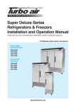
OPERATOR'S MANUAL
NETWORK SOUNDER
MODEL
DFF1
www.furuno.co.jp
IMPORTANT NOTICES
• The descriptions in this manual are intended for readers with a solid knowledge of English.
• No part of this manual may be copied or reproduced without written permission.
• If this manual is lost or worn, contact your dealer about replacement.
• The contents of this manual and equipment specifications are subject to change without notice.
• The example screens (or illustrations) shown in this manual may not match the screens you
see on your display. The screen you see depends on your system configuration and equipment
settings.
• Store this manual in a convenient place for future reference.
• FURUNO will assume no responsibility for the damage caused by improper use or modification
of the equipment (including software) by an unauthorized agent or a third party.
• When it is time to discard this product it must be done according to local regulations for disposal of industrial waste. For disposal in the USA, refer to the Electronics Industries Alliance
(http://www.eiae.org/).
i
SAFETY INSTRUCTIONS
The user and installer must read the appropriate safety instructions before attempting to install
or operate the equipment.
WARNING
Indicates a potentially hazardous situation which, if not avoided,
could result in death or serious injury.
CAUTION
Indicates a potentially hazardous situation which, if not avoided,
may result in minor or moderate injury.
Warning, Caution
Prohibitive Action
Mandatory Action
Safety instructions for the operator
WARNING
WARNING
Do not open the equipment.
Do not operate the equipment with
wet hands.
Only qualified personnel should work
inside the equipment.
Electrical shock can result.
Do not disassemble or modify the
equipment.
Do not place liquid-filled containers
on the top of the equipment.
Fire, electrical shock or serious injury can
result.
Electrical shock can result.
Turn off the equipment immediately if
it is emitting smoke or fire.
Do not install the network sounder unit
where it may be subjected to rain or
water splash.
Fire or electrical shock can result if the
power is left on.
Fire or electrical shock can result if water
gets inside the equipment.
Turn off the power immediately if water
leaks into the equipment or an object
is dropped inside the equipment.
Use the proper fuse.
WARNING
Use of a wrong fuse can damage the
equipment and may cause fire.
Continued use can cause fire or electrical
shock.
A warning label is attached to the equipment.
Do not remove these labels. If a label is missing
or illegible, contact a FURUNO agent or dealer
about replacement.
Turn off the power immediately if you
feelthe equipment is acting abnormally.
If the equipment is very warm or is
emitting strange noises turn off the
power immediately and contact your
dealer for advice.
WARNING
Name: Warning Label (1)
To avoid electrical shock, Type: 86-003-1011-2
do not remove cover. No
user-serviceable
parts Code No.: 100-236-232
ii
Safety instructions for the installer
WARNING
CAUTION
The transducer cable must be handled
carefully, following the guidelines
below.
Do not open the equipment.
Only qualified personnel should work
inside the equipment.
• Keep fuels and oils away from the
cable.
• Locate the cable away from chemicals.
• Locate the cable away from locations
where it might be damaged.
Turn off the power before beginning
the installation.
Fire or electrical shock can result if the
power is left on.
Do not turn on the power with the
transducer exposed to air.
Confirm that is no water leakage at
the transducer and temperature
sensor.
Damage to the transducer may result.
WARNING
Observe the following compass safe
distances to prevent interference to a
magnetic compass:
Water leakage can sink the vessel. Also,
confirm that neither the transducer or
sensor will loosen by vibration. The
installer is solely responsible for the
installation.
Confirm that the power supply voltage
is within the rating of this equipment.
Incorrect voltage will damage the equipment and may cause fire.
iii
Standard
compass
Steering
compass
0.30 m
0.30 m
TABLE OF CONTENTS
SYSTEM CONFIGURATION ........................................................................................... v
1. MOUNTING ................................................................................................................. 1
1.1 Equipment Lists .................................................................................................................. 1
1.2 Network Sounder ................................................................................................................ 2
1.3 Transducer 520-5PSD, 520-5MSD..................................................................................... 3
1.3.1 Mounting location ....................................................................................................... 3
1.3.2 Acceptable mounting locations .................................................................................. 4
1.3.3 Installation procedure ................................................................................................ 4
1.4 Transducer 525-5PWD (transom mount) ........................................................................... 6
1.4.1 Installation for flat hulls............................................................................................... 6
1.4.2 Installation for deep-V hulls........................................................................................ 7
1.4.3 Transducer preparation.............................................................................................. 7
1.5 Inside Hull Mount ................................................................................................................ 8
1.5.1 Necessary tools..........................................................................................................8
1.5.2 Remarks on installation.............................................................................................. 8
1.5.3 Selecting the mounting location ................................................................................. 8
1.5.4 Installation procedure................................................................................................. 9
1.6 Optional Water Temperature Sensor ST-02MSB, ST-02PSB .......................................... 10
1.7 Optional Temperature Sensors ........................................................................................ 11
1.7.1 Transom mount temperature sensor T-02MTB........................................................ 11
1.7.2 Thru-hull temperature sensor T-02MSB, T-03MSB ................................................. 12
1.8 Optionial Triducers ...........................................................................................................11
1.8.1 Thru-hull triducer 525ST-MSD ................................................................................. 13
1.8.2 Transom mount triducer 525ST-PWD...................................................................... 13
2. WIRING...................................................................................................................... 19
2.1 Optional Temperature/Speed Sensor, Temperature Sensor ............................................20
2.2 Wiring Optional 1 kW Transducer.....................................................................................21
3. INITIAL SETTINGS, OPERATION ............................................................................ 23
3.1 Selecting the Transmission Power ................................................................................... 23
3.2 MODE SW ........................................................................................................................ 24
3.3 Operation Check (LED) .................................................................................................... 25
4. MAINTENANCE......................................................................................................... 27
4.1 Maintenance ..................................................................................................................... 27
4.2 Replacing the Fuse........................................................................................................... 28
PACKING LIST ............................................................................................................ A-1
OUTLINE DRAWINGS ................................................................................................ D-1
INTERCONNECTION DIAGRAM ................................................................................ S-1
iv
SYSTEM CONFIGURATION
Network Sounder
DFF1
NavNet series
Radar
Plotter
NavNet series
Radar
Plotter
HUB*
Radar
Plotter
Radar
Plotter
Rectifier
PR-62
Matching Box
MB-1100
12-24 VDC
1 kW
100/110/220/230 VAC,
1φ, 50/60 Hz
Transducer
520-5PSD
525-5PWD
520-5MSD
Speed/temperature
sensor
ST-02MSB
ST-02PSB
Triducer
525ST-MSD
525ST-PWD
Temperature
sensor
T-02MTB
T-02MSB
T-03MSB
Transducer
50B-6/6B
50B-9B
v
Transducer
50/200-1T
50/200-12M
Note: Use only 600 W/1 kW transducer.
Use of other types will damage the transducer.
*: HUB may be connected to 3 sets of NavNet radar or plotter.
: Standard supply
: Optional supply
: External equipment
Transducer
200B-5S
1.
MOUNTING
1.1
Equipment Lists
Standard supply
Name
Network Sounder
Spare Parts
Installation Materials
Type
DFF1
SP02-05201
CP02-08100
Code No.
001-007-860
000-010-153
Qty
1
1 set
1 set
Remarks
Fuse
Power cable, LAN cable,
Self-tapping screws
Optional supply
Name
Matching Box
Cable Assy.
Cable Assy.
Code No.
MB-1100
000-041-353
MJ-A6SPF0017-010C
000-159-704-11
MJ-A6SPF0017-100C
000-159-706-11
MJ-A6SPF0017-200C
000-159-707-11
MJ-A6SPF0017-300C
000-159-708-11
MJ-A6SRMD/TM11AP8-005 000-144-463
MOD-Z072-020+
000-167-175-10
MOD-Z072-050+
000-167-176-10
MOD-Z072-100+
000-167-177-10
22S0191-2
000-802-598
525ST-MSD
000-015-263
525ST-PWD
000-015-261
520-5PSD
000-015-204
520-5PWD
000-015-126
520-5MSD
000-015-212
50B-6
000-015-042
50B-6B
000-015-043
50B-9B
000-015-065
200B-5
000-015-027
200B-5S
000-015-029
50/200-1T
000-015-170
50/200-12M
000-015-171
ST-02MSB
000-137-986
ST-02PSB
000-137-987
T-02MTB
000-040-026
T-02MSB
000-040-040
T-03MSB
000-040-027
02S4147
000-141-082
Rectifier
PR-62
Inner Hull Kit S
Triducer
Transducer
Speed/Temperature Sensor
Temperature
Sensor
Type
Remarks
For 1 kW
1 m, for NavNet
10 m, for NavNet
20 m, for NavNet
30 m, for NavNet
For HUB
2 m, for NavNet 3D
5 m, for NavNet 3D
10 m, for NavNet 3D
Thru-hull mount
Transom mount
Thru-hull mount
Transom mount
Thru-hull mount
10 m, 1 kW
15 m, 1 kW
15 m, 1 kW
10 m, 1 kW
10 m, 1 kW
10 m, 1 kW
10 m
Thru-hull mount
Thru-hull mount
Transom mount
Thru-hull mount
000-013-484
000-013-485
000-013-486
For Speed/Temp sensor,
Temp. sensor
100 VAC
110 VAC
220 VAC
000-013-487
230 VAC
Note: Use only 600 W/1 kW transducer. Use of other types will damage the transducer.
1
1.2
Network Sounder
The network sounder can be installed on a desktop, deck or on a bulkhead. When selecting a mounting location for the network sounder, keep the following in mind:
• The temperature and humidity should be moderate and stable.
• Locate the unit away from exhaust pipes and vents.
• The mounting location should be well ventilated.
• Mount the unit where shock and vibration are minimal.
• Keep the unit away from electromagnetic field-generating equipment such as
motors and generators.
• Leave slack in cables for maintenance and servicing ease.
• A magnetic compass will be affected if the network sounder is placed too close to it.
Observe the compass safe distances noted in the safety instructions to prevent disturbance to the magnetic compass.
• Fasten the network sounder to the mounting location with four self-tapping screws
(4×20).
2
1.3
Transducer 520-5PSD, 520-5MSD
1.3.1
Mounting location
.The performance of this sounder is directly related to the mounting location of the
transducer, especially for high-speed cruising. The installation should be planned in
advance, keeping the standard cable length and the following factors in mind:
• When the boat has a keel, the transducer should be at least 15-30 cm away from it.
Typical thru-hull mountings are shown in the figure on the next page.
• Air bubbles and turbulence caused by movement of the boat seriously degrade the
sounding capability of the transducer. The transducer should, therefore, be located
in a position where water flow is the smoothest. Noise from the propellers also
adversely affects performance and the transducer should not be mounted nearby.
The lifting strakes are notorious for creating acoustic noise, and these must be
avoided by keeping the transducer inboard of them.
• The transducer must always remain submerged, even when the boat is rolling,
pitching or up on a plane at high speed.
• A practical choice would be somewhere between 1/3 and 1/2 of the boat's length
from the stern. For planing hulls, a practical location is generally rather far astern,
so that the transducer is always in water regardless of the planing attitude.
22
120
24
All dimensions
in millimeters
120
28
30
68
Ship's
bow
87
68
520-5MSD
520-5PSD
Dimensions of transducers 520-5PSD, 520-5MSD
3
1.3.2
Acceptable mounting locations
Deep-V hull
* Position 1/2 to 1/3 length of the hull from stern.
* 15-30 cm from center line (inside first lifting strakes).
Transducer mounting location on deep-V hull
High speed V-planing hull
* Within the wetted bottom area
* Deadrise angle within 15°
Transducer mounting location on high speed V-planing hull
4
1.3.3
Installation procedure
1. With the boat hauled out of the water, mark the location selected for mounting the
transducer on the bottom of the hull.
If the hull is not level within 15° in any direction, fairing blocks made out of teak
should be used between the transducer and hull, both inside and outside, to keep
the transducer face parallel with the water line. Fabricate the fairing block as
shown below and make the entire surface as smooth as possible to provide an
undisturbed flow of water around the transducer.
The fairing block should be smaller than the transducer itself to provide a channel
to divert turbulent water around the sides of the transducer rather than over its
face.
BOW
Hole for
stuffing tube
Upper
half
Lower
half
Saw along slope of hull.
Construction of fairing block
2. Drill a hole just large enough to pass the threaded stuffing tube of the transducer
through the hull, making sure it is drilled vertically.
3. Apply a sufficient amount of high quality caulking compound to the top surface of
the transducer, around the threads of the stuffing tube and inside the mounting
hole (and fairing blocks if used) to ensure watertight mounting.
4. Mount the transducer and fairing blocks and tighten the locking nuts. Be sure that
the transducer is properly oriented and its working face is parallel to the water line.
Flat washer
Rubber
washer
Fairing block
Hull bottom
Hull
bottom
Deep-V Hull
Flat Hull
Note: Do not over-stress the stuffing tube and locking nuts through excessive tightening, since the wood block will swell when the boat is placed in the water. It is suggested
that the nut be tightened lightly at installation and retightened several days after the
boat has been launched.
5
1.4
Transducer 525-5PWD (transom mount)
This type of mounting is very commonly employed for outboard motor boats. Do not
use this method on an inboard motor boat because turbulence is created by the propeller ahead of the transducer.
There are two methods of installation: flush with hull (for flat hulls) and projecting from
hull (for deep V-hulls).
Flat Hull
Deep V-hull
Transom mount transducer mounting locations
1.4.1
Installation for flat hulls
A suitable mounting location is at least 50 cm away from the engine and where the
water flow is smooth.
1. Drill four pilot holes in the mounting location.
2. Attach the transducer to the bracket with self-tapping screws (supplied).
3. Adjust the transducer position so the transducer faces right to the seabed.
Note: If necessary, to improve water flow and minimize air bubbles staying on the
transducer face, incline the transducer about 5° at the rear. This may require a
certain amount of experimentation for fine tuning at high cruising speeds.
4. Fill the gap between the wedge front of the transducer and transom with epoxy
material to eliminate any air spaces.
M5x20
Tape
Transom mount transducer, mounting flush with hull
6
1.4.2
Installation for deep-V hulls
This method is employed on deep-V hulls and provides good performance because
the effects of air bubbles are minimal. Install the transducer parallel with water surface;
not flush with hull. If the boat is placed on a trailer care must be taken not to damage
the transducer when the boat is hauled out of the water and put on the trailer.
M5x20
M5x20
No.2
M5x14
Transom mount transducer, projecting from hull
1.4.3
Transducer preparation
Before putting the boat in water, wipe the face of the transducer thoroughly with a detergent liquid soap. This will lessen the time necessary for the transducer to have good
contact with the water. Otherwise the time required for complete "saturation" will be
lengthened and performance will be reduced.
Note: Do not paint the transducer. Performance will be affected.
7
1.5
Inside Hull Mount
This mounting method is available for FRP boats.
1.5.1
Necessary tools
You will need the following tools:
• Sandpaper (#100)
• Silicone sealant
• Silicone grease
1.5.2
Remarks on installation
• Turn off the engine and anchor the boat while installing the equipment.
• Install the transducer in the engine room.
1.5.3
Mounting location
Keep the following points in mind when selecting a mounting location:
• The mounting location should be where the hull is of single-hull thickness and is
void of air or flotation materials other than solid fiberglass between the transducer
face and the water.
• Do not place the transducer over hull struts or ribs which run under the hull.
• Avoid a location where the rising angle of the hull exceeds 15°, to minimize the
effect of the boat's rolling.
• You will finalize the mounting location through some trial and error. The procedure
for this is shown later.
Center line
50cm
50cm
1/2
1/3
15cm
15cm
Mounting location
for transducer
Inside-hull transducer mounting location
8
1.5.4
Installation procedure
1. Clean the transducer face to remove any foreign material. Lightly roughen the
transducer face with #100 sandpaper. Also, roughen the inside of the hull where
the transducer is to be mounted.
2. Warm the silicone sealant to 40°C before usage to soften it. Coat the transducer
face and mounting location with silicone sealant.
Transducer face
Silicone sealant
Coating the transducer face with silicone sealant
3. Press the transducer firmly down on the hull and gently twist it back and forth to
remove any air which may be trapped in the silicone sealant.
Twist to squeeze out air bubbles.
Silicone sealant
Hull
Attaching transducer to hull with silicone sealant
4. Connect this unit to NavNet equipment and turn on the NavNet equipment.
5. Set up the NavNet equipment to show “single frequency display”.
6. Set the gain to “50”.
7. Set the range to “10”.
Case 1
The installation is proper if the bottom echo is displayed in red and the depth indication is shown. Go to step 9.
Case 2
The bottom echo is not displayed in red when ultrasound attenuation is great. Relocate the transducer as shown in step 8
8. Re-locating the transducer.
1) Turn off the power.
2) Detach the transducer. Insert a knife or wooden stick under transducer to
remove it
3) Repeat steps 1 thru 7.
9. Fix the transducer.
9
1.6
Optional Water Temperature Sensor ST-02MSB,
ST-02PSB
Select a suitable mounting location considering the following points:
• Select a mid-boat flat position. The sensor does not have to be installed perfectly
perpendicular. The sensor must not be damaged in dry-docking operation.
• Select a place apart from equipment generating heat.
• Select a place in the forward direction viewing from the drain hole, to allow for circulation of cooling water.
• Select a place free from vibration.
Procedure
1. Dry-dock the boat.
2. Make a hole of approx. 51 mm in diameter in the mounting location.
3. Unfasten locknut and remove the sensor section.
4. Apply high-grade sealant to the flange of the sensor.
5. Pass the sensor casing through the hole.
6. Face the notch on the sensor toward boat's bow and tighten the flange.
7. Set the sensor section to the sensor casing and tighten the locknut.
8. Launch the boat and check for water leakage around the sensor.
Locknut
Face "notch"
toward bow.
Flange nut
Coat with
silicone sealant.
51
123
Brim
φ77
Speed/Temperature sensor ST-02MSB, ST-02PSB
10
1.7
Optional Temperature Sensors
1.7.1
Transom mount temperature sensor T-02MTB
• Fix the cable at a convenient location with cable clamp.
• When the cable is led in through the transom board, make a hole of approx. 17 mm
in diameter to pass the connector. After passing the cable, fill the hole with a sealing compound.
D>50cm
D
M5x20
Mount sensor
flush with hull bottom.
Temperature sensor T-02MTB
11
1.7.2
Thru-hull temperature sensor T-02MSB, T-03MSB
Select a suitable mounting location considering the following points:
• Select a mid-boat flat position. The sensor does not have to be installed perfectly
perpendicular. However, the location should not be such that the transducer may be
damaged when the boat is dry-docked.
• Locate away from equipment which gives off heat.
• Locate away from drain pipes.
• Select a location where vibration is minimal.
Sensor Holder
Sensor
Cable
Locknut
Locknut
Washer
Rubber Gasket
Locknut
Washer
Rubber Gasket
φ21 mm
Apply sealant.
Apply sealant.
Thicker
than 25 mm
Holder Guide
T-02MSB
T-03MSB
Assembling temperature sensor T-02MSB, T-03MSB
12
1.8
Optional Triducers
1.8.1
Thru-hull triducer 525ST-MSD
See section 1.2 for how to install the 525ST-MSD.
φ79 mm
133 mm
2.00°
Thread
f51 mm
27 mm
1.8.2
7 mm
140 mm
Unit: mm
Transom mount triducer 525ST-PWD
Pre-test for speed and temperature
Connect the sensor to the instrument and spin the paddlewheel. Check for a speed
reading and the approximate air temperature. If there is no reading, return the sensor
to your place of purchase.
Tools and materials needed
• Scissors
• Masking tap
• Safety goggles
• Dust mask
• Electric drill
• Drill bit for:
- Bracket holes: 4mm, #23, or 9/64"
- Fiberglass hull: chamfer bit (preferred), 6mm, or 1/4"
- Transom hole: 19mm or 3/4" (optional)
- Cable clamp holes: 3mm or 1/8"
• Screwdrivers
13
• Straight edge
• Marine sealant
• Pencil
• Zip-ties
• Water-based antifouling paint (mandatory in salt water).
Mounting location
To ensure the best performance, the sensor must be submerged in aeration-free and
turbulence-free water. Mount the sensor close to the centerline of the boat. On slower
heavier displacement hulls, positioning it farther from the centerline is acceptable.
Allow adequate space above the bracket for it to release and rotate the sensor upward.
Height without
speed sensor
191mm (7-1/2")
Height
Height with
speed sensor
213mm (8-1/2")
Height required at mounting location
Note 1: Do not mount the sensor in an area of turbulence or bubbles: near water intake or discharge openings; behind strakes, struts, fittings, or hull irregularities; behind
eroding paint (an indication of turbulence).
Note 2: Avoid mounting the sensor where the boat may be supported during trailering,
launching, hauling, and storage.
Note 3: For single drive boat, mount on the starboard side at least 75 mm (3") beyond the swing radius of the propeller.
75 mm (3")
minimum beyond
swing radius
Mounting location on single drive boat
Note 4: For twin drive boat, mount between the drives.
14
Installation of bracket
1. Cut out the installation template (enclosed with transducer) along the dotted line.
2. At the selected location, position the template, so the arrow at the bottom is
aligned with the bottom edge of the transom. Being sure the template is parallel to
the waterline, tape it in place.
Align template vertically.
Deadrise angle
Slope of hull
parallel to
waterline
Align template arrow with
bottom edge of transom.
Positioning the template
Warning: Always wear safety goggles and a dust mask.
3. Using a 4 mm, #23, or 9/64" bit, drill three holes 22 mm (7/8") deep at the locations indicated. To prevent drilling too deeply, wrap masking tape around the bit 22
mm (7/8") from the point.
Fiberglass hull: Minimize surface cracking by chamfering the gelcoat. If a chamfer bit or countersink bit is not available, start drilling with a 6mm or 1/4" bit to a
depth of 1 mm (1/16").
4. If you know your transom angle, the bracket is designed for a standard 13° transom angle.
11°-18° angle: No shim is required. Skip to step 3 in "Adjusting".
Other angles: The shim is required. Skip to step 2 of "Adjusting".
If you do not know the transom angle, temporarily attach the bracket and sensor to
the transom to determine if the plastic shim is needed.
5. Using the three #10 x 1-1/4" self-tapping screws, temporarily screw the bracket to
the hull. DO NOT tighten the screws completely at this time. Follow the step 1-4 in
"Attaching the sensor to the bracket", before proceeding with "Adjusting".
15
Attaching the sensor to the bracket
1. If the retaining cover near the top of the bracket is closed, open it by depressing
the latch and rotating the cover downward.
Step 1
Step 2
Latch
Pivot
arm (2)
Retaining
cover
Step 3
Slot (2)
Step 4
Attaching the sensor to the bracket
2. Insert the sensor's pivot arms into the slots near the top of the bracket.
3. Maintain pressure until the pivot arms click into place.
4. Rotate the sensor downward until the bottom snaps into the bracket.
5. Close the retaining cover to prevent the accidental release of the sensor when the
boat is underway.
Adjusting
1. Using a straight edge, sight the underside of the sensor relative to the underside
of the hull. The stern of the sensor should be 1-3 mm (1/16-1/8") below the bow of
the sensor or parallel to the bottom of the hull.
Note: Do not position the bow of the sensor lower than the stern because aeration
will occur.
2. To adjust the sensor's angle relative to the hull, use the tapered plastic shim provided. If the bracket has been temporarily fastened to the transom, remove it. Key
the shim in place on the back of the bracket.
2°-10° transom angle (stepped transom and jet boats): Position the shim with
the tapered end down.
16
19°-22° transom angle (small aluminum and fiberglass boats): Position the
shim with the tapered end up.
2°-10° 11° transom angle
transom
NO SHIM
angle
19°-22°
transom
angle
shim with
taper up
shim with
taper down
YES
YES
YES
parallel
parallel
parallel
12°-18° transom angle
NO SHIM
YES
NO
angle
reversed
slight
angle
NO
angle
too steep
Sensor position and transom angle
3. If the bracket has been temporarily fastened to the transom, remove it. Apply a
marine sealant to the threads of the three #10 x 1-1/4" self-tapping screws to prevent water seeping into the transom. Screw the bracket to the hull. Do not tighten
the screws completely at this time.
4. Repeat step 1 to ensure that the angle of the sensor is correct.
Note: Do not position the sensor farther into the water than necessary to avoid
increasing drag, spray, and water noise and reducing boat speed.
5. Using the vertical adjustment space on the bracket slots, slide the sensor up or
down to provide a projection of 3 mm (1/8”). Tighten the screws.
Cable cover
Cable
clamp
50 mm (2")
Hull projection 3 mm (1/8")
Vertical adjustment and cable routing
17
Cable routing
Route the sensor cable over the transom, through a drain hole, or thorough a new hole
drilled in the transom above the waterline.
Never cut the cable or remote the connector; this will void the warranty. Always wear
safety goggles and a dust mask.
1. If a hole must be drilled, choose a location well above the waterline. Check for
obstructions such as trim tabs, pumps, or wiring inside the hull. Mark the location
with a pencil. Drill a hole through the transom using a 19 mm or 3/4" bit (to accommodate the connector).
2. Route the cable over or through the transom.
3. On the outside of the hull secure the cable against the transom using the cable
clamps. Position a cable clamp 50 mm (2") above the bracket and mark the
mounting hole with a pencil.
4. Position the second cable clamp halfway between the first clamp and the cable
hole. Mark this mounting hole.
5. If a hole has been drilled in the transom, open the appropriate slot in the transom
cable cover. Position the cover over the cable where it enters the hull. Mark the
two mounting holes.
6. At each of the marked locations, use a 3 mm or 1/8" bit to drill a hole 10 mm (3/8")
deep. The prevent drilling too deeply, wrap masking tape around the bit 10 mm (3/
8") from the point.
7. Apply marine sealant to the threads of the #6 x 1/2" self-tapping screw to prevent
water from seeping into the transom. If you have drilled a hole through the transom, apply marine sealant to the space around the cable where it passes through
the transom.
8. Position the two cable clamps and fasten them in place. If used, push the cable
cover over the cable and screw it in place.
9. Route the cable to the instrument being careful not to tear the cable jacket when
passing it though the bulkhead(s) and other parts of the boat. To reduce electrical
interference, separate the sensor cable from other electrical wiring and "noise"
sources. Coil any excess cable and secure it in place with zip-ties to prevent damage.
18
2.
WIRING
Connect the power cable, transducer cable, external equipment and ground wire as
shown in the figure below.
DFF1
XDR
NETWORK
12-24 VDC
1.1-0.4 A
3 GND
1+
MODE SW
1 2 3 4
For NavNet, NavNet vx2:
MJ-A6SAPF-0017-050C. 5 m
(10/15/20/30 m, option)
GROUND WIRE
IV-1.25sq
NAVNET
For NavNet 3D:
or HUB
MOD-Z072-XXX+
(option, XXX=length: 2, 5, 10 m)
GROUND
Black
White
Shield (green)
TRANSDUCER
BATTERY
12-24 VDC
DFF1, rear view
Ground
Connect the ground wire (1.25sq) to ship's ground to prevent interference to the picture. Shorten the ground wire as much as possible. For FRP vessels, install a ground
plate that measures about 20 cm by 30 cm on the outside of the hull bottom to provide
a ground point.
CAUTION
Ground the equipment
to prevent mutual
interference.
Note: Use a "closed-type" lug (
) to make the ground connection at the network
sounder. Do not use an "open-type" lug (
).
External KP
Consult with your dealer if connection of an external KP is required to reduce interference from another transducer.
19
2.1
Optional Temperature/Speed Sensor,
Temperature Sensor
Connect the temperature/speed sensor or temperature sensor to the XDR port with
the converter connector (Type: 02S4147, Code No.: 000-141-082, option).
MJ-A6SRMD
MJ-A10SPF
SHIELD
TEMP
TEMP0V/SPD0V
SPD
+V
NC
1
2
3
4
5
6
NC
NC
NC
NC
NC
NC
NC
XDR+
XDR SHIELD
XDR-
1
2
3
4
5
6
7
8
9
10
Temperature
sensor OR
Temperature/
speed
sensor
MJ-A10SRMD
Transducer
4
7
3
1
2
5
6
8
9
10
TEMP
TEMP0V
SPD0V/ SHIELD
SPD
+V
XDR port on the
NC
DFF1
NC
XDR+
XDR SHIELD
XDR-
Connection of temperature/speed sensor
Connect to XDR port
at network sounder
MJ-A10SPF
MJ-A6SRMD
MJ-A10SRMD
Tape connector with
self-vulcanizing tape
and then vinyl tape
to waterproof
connector. Bind tape
end with cable tie.
Temperature, Speed/temperature Transducer connector
sensor connector
Connection of transducer, temperature sensor, speed/temperature sensor
20
2.2
Wiring Optional 1 kW Transducer
To connect optional transducer 50B-6, 50B-6B, 50B-9B, 200B-5, 200B-5S, 50/200-1T
or 50/200-12M, the optional Matching Box MB-1100 is required.
02P6168
50kHz
J2
50B-6/6B
50B-9B
SHIELD
J1
TB2
1
BLK
200kHz
Jumper block setting
J2: Full power output
J1: Reduced power output
RED
BLK
RED
TB1
2
3
3
2
4
1
Shield
WHT
BLK
5
200B-5S
50/200-1T
or
50/200-12M
TO NETWORK SOUNDER
(Cable is fitted with
8P connector. 8P-10P
converter connector is
required.)
TB2
(SHIELD)
(BLK)
(BLU)
(GRN)
(RED)
1
2
3
4
5
50K
200K
Common
Common
Matching Box MB-1100
Matching Box Kit (Type: MB-1100, Code No.: 000-041-353)
Name
Type
Code No.
Qty
Matching Box
MB-1100
000-041-000
1
Crimp-on Lug
FV1.25-3 Red
000-538-113
6
Cord Lock
NC-1
000-516-650
1
Remarks
Cable w/8P connector supplied for connection to network sounder
For use with separate transducer
Fabrication of transducer cable
Fabricate the transducer cable as illustrated below to connect it to the Distribution Box.
Vinyl sheath
Crimp-on lug
FV1.25-3, Red
Clamp here.
Shield
Taping
Vinyl tube
Fabrication of transducer cable
21
This page is intentionally left blank.
22
3.
INITIAL SETTINGS, OPERATION
WARNING
Do not open the equipment
unless totally familiar with
electrical circuits and
service manual.
Only qualified personnel
should work inside the
equipment.
3.1
Selecting the Transmission Power
The default transmission power is 600 W. If the 1 kW transducer is installed, turn on
the #1 segment of DIP SW S2 on the pcb 02P6353 inside the network sounder.
1. Detach the power cable.
2. Detach the cover of the DFF1; grasp the cover at opposing sides with hands, pull
outward slightly and lift up to detach.
3. Loosen three screws fixing the inside cover, and slide cover forward to detach it.
4. Set the #1 segment of DIP SW S2 according to transducer connected.
OFF
02P6353
4
3
2
1
J17
ON
600 kW transducer
S2
OFF
LAN connector
4
3
2
1
ON
1 kW transducer
PCB 02P6353
5. Close the inside and outside covers and connect the power cable.
23
3.2
MODE SW
The MODE switch provides the functions described in the table below. Remove the
rubber cap to access the switch and set switches with a plastic screwdriver or the like.
XDR
MODE SW
1 2 3 4
NETWORK
12-24 VDC
1.1-0.4 A
3 GND
1+
ON
↓
2 1
2
3
4
OFF
ON
1
2
3
4
Description of MODE SW
SW
No.
Function, description
Setting content
1
(Default:ON)
Power from NavNet
OFF: Sounder powered on/off by NavNet
ON: Sounder not powered on/off by NavNet
2
Default: OFF)
IP number
(Currently no use)
OFF: IP0
ON: IP1
3
Default: OFF)
Factory testing
OFF: Testing OFF
ON: Testing ON
4
(Default: ON)
Automatic IP setting
(Currently no use)
OFF: Automatic IP enabled
ON: Automatic IP disabled
For NavNet 3D, turn off all switches.
24
3.3
Operation Check (LED)
The network sounder is powered on/off from ship’s switchboard. The LED on the network sounder lights or flashes according to equipment state, as described in the table
below.
LED state
Meaning
Lighting continuously*
NavNet is not showing the sounder display, or
sounder is not connected to NavNet
Flashing every two seconds
Normal operation
Flashing every four seconds
Factory test mode
* The LED lights for approximately 20 seconds after turning on the power while the
equipment is being initialized.
LED
DFF1, top view
25
This page is intentionally left blank.
26
4.
MAINTENANCE
WARNING
Do not open the equipment
unless totally familiar with
electrical circuits and
service manual.
Only qualified personnel
should work inside the
equipment.
4.1
Maintenance
Regular maintenance is essential for good performance. Check the items listed in the
table below monthly to help keep your equipment in good shape for years to come.
Checking
Item
Action
Transducer cable
Check that cable is tightly fastened and is not damaged.
Replace if damaged.
Power cable, transducer
cable plug
Check that they are tightly fastened and not damaged.
Refasten if necessary. Replace if damaged.
Ground
Check for corrosion. Clean if necessary.
Power supply voltage
Check voltage. If out of rating correct problem.
Cleaning the network
sounder’s cabinet
Dust or dirt on the cabinet may be removed with a dry cloth.
Do not use chemical-based cleaners to clean the cabinet;
they can remove paint and markings.
Transducer
Marine life on the transducer face will result in a gradual
decrease in sensitivity. Check the transducer face for
cleanliness each time the boat is dry-docked. Carefully
remove any marine life with a piece of wood or fine-grade
sandpaper.
27
4.2
Replacing the Fuse
The two 3 A fuses (Type: FGBO-A 125V 3A PBF, Code No. 000-155-850-10) in the
snap-in fuse holder on the power cable protect the equipment from equipment fault
and reverse polarity of the ship's mains. If the equipment cannot be powered, a fuse
may have blown. Find out the cause for blown fuse before replacing a fuse. If a fuse
blows again after replacement, contact a FURUNO agent or dealer for advice.
WARNING
Use the proper fuse.
Use of a wrong fuse can result in damage
to the equipment or cause fire.
28
FURUNO
DFF1
SPECIFICATIONS OF THE NETWORK SOUNDER
DFF1
1. GENERAL
1.1.
Output Power
600 W/ 1 kW rms nominal, 1 kW requires optional MB-1100
1.2.
TX Frequency
50 kHz or 200 kHz, 50/200 kHz exchangeable
1.3.
Amplifier type
Wide dynamic linear amp (double superheterodyne)
1.4.
Network protocol
Ethernet 100/10BASE-TX
1.5.
Depth Range and Pulse Repetition Rate
Range (m)
PRR ( /min.)
2
3000
5
3000
10
1990
40
485
100
195
200
95
400
65
1200
34
2. POWER SUPPLY
12-24 VDC: 1.1-0.4 A (at 1 kW output)
3. ENVIRONMENTAL CONDITION
3.1. Ambient Temperature
-15°C to +55°C
3.2. Relative Humidity
93% at 40°C
3.3. Dustproofing, waterproofing
IP20 (not waterproof)
(IEC60529)
3.4. Vibration (IEC 60945 Ed4)
- 2-5 Hz and up to 13.2 Hz with an excursion of ±1 mm ±10 %
(7 m/s2 maximum acceleration at 13.2 Hz)
- 13.2-100 Hz with a constant maximum acceleration of 7 m/s2
4. COATING COLOR
4.1. Main Unit
N3.0
SP - 1
E2036S01A
PACKING LIST
02GB-X-9851 -1
DFF1-J/E
N A M E
ユニット
O U T L I N E
DESCRIPTION/CODE №
1/1
A-1
Q'TY
UNIT
ネットワーク魚探
1
DFF1
NETWORK SOUNDER
000-010-154-00
予備品
SPARE PARTS
SP02-05201
ヒューズ
2
FGBO-A 125V 3A PBF
FUSE
000-155-850-10
工事材料
INSTALLATION MATERIALS
CP02-08100
ケーブル組品MJ
1
MJ-A3SPF0028-035C
POWER CABLE ASSY.
000-164-952-10
ケーブル組品MJ
1
MJ-A6SPF0017-050C
CABLE ASSY.
000-159-705-11
+トラスタッピンネジ 1シュ
4
4X20 SUS304
SELF-TAPPING SCREW
000-158-850-10
図書
DOCUMENT
取扱説明書
OPERATOR'S MANUAL
1
OM*-20360-*
000-164-956-0*
**
コ-ド番号末尾の[**]は、選択品の代表コードを表します。
CODE NUMBER ENDING WITH "**" INDICATES THE CODE NUMBER OF REPRESENTATIVE MATERIAL.
型式/コード番号が2段の場合、下段より上段に代わる過渡期品であり、どちらかが入っています。 なお、品質は変わりません。
TWO TYPES AND CODES MAY BE LISTED FOR AN ITEM. THE LOWER PRODUCT MAY BE SHIPPED IN PLACE OF THE UPPER
PRODUCT. QUALITY IS THE SAME.
(略図の寸法は、参考値です。 DIMENSIONS IN DRAWING FOR REFERENCE ONLY.)
02GB-X-9851
D-1
D-2
C
B
A
1 2 3
DFF1
MB-1100
NOTE
*1: SHIPYARD SUPPLY.
*2: OPTION.
*3: FITTED AT FACTORY.
*4: CHANGE JUMPER SETTING OF DFF1.
*4
50B-6/6B 200B-5/5S
50B-6G/9B
5 2 1 4 3
10P
1 2 3 4 5
MB-1100
*1
IV-1.25sq.
*1
IV-2sq.
XDR
MJ-A10SPF
02S4089
8P
8P
FM-214-8P
整流器
RECTIFIER
PR-62 *2
5 6
MJ-A3SPF0028-035C
3.5m
*1
DPYC-1.5
注記
*1)造船所手配。
*2)オプション。
*3)工場にて取付済み。
*4)DFF1のジャンパー設定変更が必要。
100/110/
220/230VAC,
1φ,50/60Hz
12-24VDC
*3
MJ-A3SPF
J1
1 (+)
シロ WHT
2 (-)
クロ BLK
3 SHIELD
ミドリ GRN
TXP
TXN
RXP
P_SW_P
P_SW_N
RXN
NC
NC
DWG.No.
SCALE
T.TAKENO
T.YAMASAKI
1
2
3
4
5
6
7
8
C2036-C01- B
MASS
4
*3
(10/15/20/30m *2) MJ-A6SPF
MJ-A6SPF0017-050C,5m,φ6
1 E_RD_P 指示部
P
P
2 E_RD_N DISPLAY UNIT
3 E_TD_P (NAVNET:NAV1,VX2)
P
4 E_TD_N
P
5 NC
6 SHIELD
*3
*3
*2
RJ-45
RJ-45
J5
MOD-Z072,2/5/10m,φ6
TXP 1
1 E_TD_P マルチファンクションディスプレイ
P
TXN 2
2 E_TD_N MULTI FUNCTION DISPLAY
RXP 3
3 E_RD_P MFDBB,MFD8/12
P_SW_P 4
4 SW_P
または OR
P P
P_SW_N 5
5 SW_N
スイッチングハブ
RXN 6
6 E_RD_N
SWITCHING HUB
NC 7
7 PWR_SW_P HUB-100
*2
P
NC 8
8 PWR_SW_N
*3
RJ-45
kg
28/Apr/08 R.Esumi
10/Mar/08
CHECKED
10/Mar/08
APPROVED
DRAWN
50/200-1T
50/200-12M
L
H
520-5PSD
520-5MSD
520-5PWD
送受波器
TRANSDUCER
*3
MJ-A10SPF
FUSE
3A
8m
(+)
(-)
GND
COMMON
50K
FG
COMMON
200K
FG
50K
200K
COMMON
COMMON
RED
BLU
GRN
BLK
XDR
XDR
J4
SPD_XDR
+12V
SPD/TD_ID_0V
TEMP_XDR
TD_ID_XDR
NC
TEMP_0V
XDR_P
XDR SHIELD
XDR_M
アカ
アオ
ミドリ
クロ
J4
ネットワーク魚探
NETWORK SOUNDER NETWORK
12-24VDC
J5
DFF1
*2
REF.No.
02-158-1001-2
NAME
名称
TITLE
520-5PSD
520-5MSD
520-5PWD
送受波器
TRANSDUCER
相互結線図
NETWORK SOUNDER
INTERCONNECTION DIAGRAM
DFF1
ネットワーク魚探
T-02MTB または ST-02MSB
ST-02PSB
T-03MSB
OR
水温・船速センサー付 T-02MSB *2
*2
送受波器
水温・船速センサー
温度センサー
TRANSDUCER W/ SENSOR
TEMP/SPEED SENSOR
TEMP SENSOR
520ST-PWD
524ST-MSD
525ST-MSD
525ST-PWD
MJ-A10SPF
02S4147 *2
*3
MJ-A6SPF
1
2
3
4
5
6
*3
MJ-A6SPF
MJ-A6SRMD
1
2
3
4
5
6
1
2
3
4
5
6
7
8
9
10
3
MJ-A10SRMD
2
1
*3
MJ-A10SPF
1
2
3
4
5
6
7
8
9
10
*3
MJ-A10SPF
XDR
J4
SPD_XDR
+12V
SPD/TD_ID_0V
TEMP_XDR
TD_ID_XDR
NC
TEMP_0V
XDR_P
XDR SHIELD
XDR_M
1
2
3
4
5
6
7
8
9
10
8
9
10
1
S-1
The paper used in this manual
is elemental chlorine free.
・FURUNO Authorized Distributor/Dealer
9-52 Ashihara-cho,
Nishinomiya, 662-8580, JAPAN
Telephone : +81-(0)798-65-2111
Fax
: +81-(0)798-65-4200
All rights reserved.
Printed in Japan
A : FEB . 2007
B : MAY 08, 2008
Pub. No. OME-20360-B
(DAMI )
DFF1
*00016495711*
*00016495711*
* 0 0 0 1 6 4 9 5 7 1 1 *