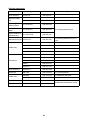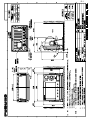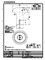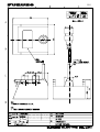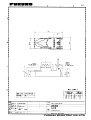
1
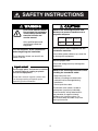
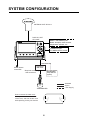
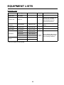
Installation Manual
COLOR GPS/PLOTTER/SOUNDER
GP-7000F
SAFETY INSTRUCTIONS ............................................................................ i
SYSTEM CONFIGURATION ....................................................................... ii
EQUIPMENT LISTS.................................................................................... iii
1. INSTALLATION ..................................................................................... 1
1.1
1.2
1.3
1.4
Display Unit .................................................................................................................. 1
Antenna Unit................................................................................................................. 4
Transducer ................................................................................................................... 5
Optional Speed/Water Temperature Sensor ST-02MSB, ST-02PSB......................... 18
2. WIRING ................................................................................................ 19
3. ADJUSTMENTS .................................................................................. 26
3.1
3.2
3.3
3.4
3.5
3.6
3.7
3.8
Choosing Position Data Source.................................................................................. 26
Choosing Port I/O Format........................................................................................... 28
Echo Sounder Settings ............................................................................................... 30
Choosing Data Source(s) ........................................................................................... 32
Calibrating NMEA Depth, Speed and Water Temperature Data ................................ 33
Waypoint, Route Format............................................................................................. 34
External Event Format ................................................................................................ 34
Primary, Secondary Unit (C-link) ................................................................................ 35
PACKING LIST ........................................................................................ A-1
OUTLINE DRAWINGS............................................................................. D-1
INTERCONNECTION DIAGRAM ............................................................ S-1
www.furuno.co.jp
The paper used in this manual
is elemental chlorine free.
・FURUNO Authorized Distributor/Dealer
9-52 Ashihara-cho,
Nishinomiya, 662-8580, JAPAN
Telephone : +81-(0)798-65-2111
Fax
: +81-(0)798-65-4200
All rights reserved.
Printed in Japan
A : AUG . 2004
C1 : JUN . 21, 2007
Pub. No. IME-44291-C1
(HIMA )
GP-7000F
*00014914012*
*00014914012*
* 0 0 0 1 4 9 1 4 0 1 2 *
SAFETY INSTRUCTIONS
CAUTION
WARNING
ELECTRICAL SHOCK HAZARD
Observe the following compass safe
distances to prevent interference to a
magnetic compass:
Do not open the equipment
unless totally familiar with
electrical circuits and
service manual.
Only qualified personnel
should work inside the
equipment.
Display
unit
Standard
compass
Steering
compass
0.70 m
0.45 m
Use the power cable supplied with the
installation materials.
Turn off the power at the switchboard
before beginning the installation.
Use of other power cables may cause fire
or damage the equipment.
Fire or electrical shock can result if the
power is left on.
Use the proper fuse.
Use of the wrong fuse may damage the
equipment.
Organic solvent
Do not apply paint, anti-corrosive sealant
or contact spray to coating or plastic
parts of the equipment.
Observe the following precautions when
handling the transducer cable:
- Keep away from oils.
- Choose a working area where the
cable will not be damaged during
installation.
- Do not paint the cable.
Those items contain organic solvents that
can damage coating and plastic parts,
especially plastic connectors.
The sheath of the cable is made of
chloroprene (or polyvinyl chloride).
Those materials easily deteriorate in
the presence of organic solvents
(toulene, etc.) found in paints. For
that reason keep the cable away from
ship's paint house.
i
SYSTEM CONFIGURATION
ANTENNA UNIT GPA-017
DISPLAY UNIT
GP-7000F
NMEA1 and NMEA2 ports:
Radar, autopilot, video sounder,
temperature indicator, etc.
PC/NMEA IN port:
PC, NMEA device, buzzer
Power Source
12-24 VDC
Distributor
MB-1000*
* Required when using
1 kW transducer.
Speed/Water
Temp Sensor
(option)
: Standard
TRANSDUCER
How to remove the hard cover
Place your thumbs at the center
of the cover, and then lift the cover
while pressing it with your thumbs.
ii
: Option
: User Supply
EQUIPMENT LISTS
Standard supply
Name
Display Unit
Type
GP-7000F
Code No.
Qty
-
1
Remarks
-
1
System also available without antenna (for boats
which already have an
appropriate antenna)
CP14-06400
000-041-183
1
Signal cable and power
cable
Accessories*
FP20-01100
000-042-239
1
Spare Parts*
SP14-03201
004-371-980
1
520-5PSD
000-015-204
525-5PWD
000-146-966
520-5MSD
000-015-212
525ST-MSD
000-015-263
525ST-PWD
000-015-261
Antenna Unit
GPA-017
Installation
Materials*
Transducer
Triducer
*: See list at back of this manual.
iii
Choose
one
Also available without transducer (for boats with transducer already installed)
Optional equipment
Name
Type
Code No
Qty
GPS Antenna
GPA-017S
000-040-541
Antenna Cable
Set
CP20-01700
004-372-110
30 m, antenna cable extension
CP20-01710
004-372-120
50 m, antenna cable extension
Right Angle
Antenna Base
No.13-QA330
000-803-239
L-angle Antenna
Base
No.13-QA310
000-803-240
Antenna Base for
No.13-RC5160
Rail Mounting
000-806-114
Mast Mounting Kit CP20-01111
004-365-780
For mounting antenna unit
For mounting antenna unit on a
mast
MJ-A6SPF0012-050C
000-154-053-10
6P - 6P, 5 m
MJ-A6SPF0012-100C
000-154-037-10
6P - 6P, 10 m
MJ-A6SPF0003-050C
000-154-054-10
6P, 5 m
MJ-A7SPF0007-050C
000-154-028-10
7P, 5 m
Cable Assy.
50B-6
000-015-042
50B-6G
000-015-016
200B-5S
000-015-029
200B-5
000-015-027
50/200-1T
000-015-170
Inner Hull Kit S
22S0191-2
000-802-598
Distributor
MB-1000
000-040-809
For 1 kW transducer
02S4089
000-133-622
For Distributor MB-1000
02S4147-0
000-141-082
For sensor
Sensor
ST-02PSB
000-137-987
Sensor
ST-02MSB
000-137-986
Transducer
Cable Assy.
Speed/water temperature sensor
iv
1.
INSTALLATION
1.1
Display Unit
The display unit may be mounted on a desktop, overhead or flush mounted in a console.
Mounting considerations
Choose a mounting location for the display unit considering the following points:
• Choose a location where the controls can be easily operated.
• Leave sufficient space around the unit to facilitate checking and maintenance. See the outline
drawing at the back of this manual for recommended maintenance space.
• Locate the unit out of direct sunlight because of heat that can build up inside the cabinet.
• The operating temperature range is -15°C to 55°C (5°F to 131°F).
• Locate the unit well away from exhaust gases and other active gases.
• The location should be well ventilated.
• Choose a location where shock and vibration are minimal.
• Be sure the mounting location is strong enough to support the weight of the unit, particularly in
overhead mounting. If necessary reinforce the mounting location.
• A magnetic compass will be affected if the display unit is placed too close to the compass.
Observe the following compass safe distances to prevent deviation to the compass.
Standard compass, 0.70 m, Steering compass, 0.45 m.
1
Mounting
Desktop, overhead mounting
1. Fix the hanger to the mounting location with four self-tapping screws (5x20). See the outline
drawing on page D-1 for complete mounting dimensions.
2. Loosely screw the knob bolts into the display unit.
3. Set the display unit to the hanger and tighten the knob bolts.
4. Attach the hard cover to the display unit to protect the LCD.
FIXING HOLE
Unit: mm
Display unit, mounting dimensions for desktop or overhead mounting
2
Flush mounting
B
A
If the thickness of the console is 11-14 mm, use the washer head
screws (M4x20) supplied with the installation materials. If it is
thicker than those dimensions, the length of the screws should
be the thickness of the console plus 7.3 mm ± 1.5 mm. The
length of the threaded portion to be inserted to the display unit
should not exceed 7 mm (B = 7).
A: Thickness of console
1. Prepare a cutout in the mounting location using the template provided.
2. Fix the display unit with six washer head screws (M4x20) provided.
52
80
150
Service
Clearance
Unit: mm
Mounting dimensions for flush mounting
3
1.2
Antenna Unit
Refer to the antenna unit outline drawing at the back of this manual for mounting instructions.
When selecting a mounting location consider the following points:
• Select a location out of the radar and Inmarsat beams. Those beams will obstruct or prevent
reception of the GPS satellite signal.
• There should be no interfering object within the line-of-sight to the satellites. Objects within lineof-sight to a satellite, for example, a mast, may block reception or prolong acquisition time.
• Locate the antenna well away from the antenna of a VHF radiotelephone to prevent interference.
• Mount the antenna unit as high as possible. Mounting it this way keeps it free of interfering
objects and water spray, which can interrupt reception of GPS satellite signal if the water
freezes.
Note: If the antenna cable is to be passed through a hole in a bulkhead which is too small to pass
the connector, disassemble the connector with radio pincers and a monkey wrench. After passing
the cable through the hole assemble the connector as below.
Gasket
Washer
Shield
Clamping Nut
Pin (Solder.)
Housing
How to assemble the antenna connector
4
1.3
Transducer
Inside-hull mounting
The thru-hull mount transducer (520-5PSD, 520-5MSD) may also be installed inside the hull, following the procedure below.
Necessary tools
You will need the following tools:
• Sandpaper (#100)
• Silicone sealant
Remarks on installation
• Turn off the engine and anchor the boat while installing the equipment.
• Install the transducer in the engine room.
• Do not turn on the echo sounder except if installing the transducer by the inside-hull mounting
method. The transducer may become damaged if the power is turned on in other types of
installations.
Choosing the mounting location
Keep the following points in mind when choosing a mounting location:
• The mounting location should be where the hull is of single-hull thickness and is void of air or
flotation materials other than solid fiberglass between the transducer face and the water.
• Do not place the transducer over hull struts or ribs that run under the hull.
• Avoid a location where the rising angle of the hull exceeds 15°, to minimize the effect of the
boat's rolling.
• You will finalize the mounting location through some trial and error. The procedure for this is
shown later.
1/2
Centerline
1/3
50 cm
50 cm
15 cm
15 cm
Transducer
mounting
location
Inside-hull transducer mounting location
5
Attaching the transducer
1. Clean the transducer face to remove any foreign material. Lightly roughen the transducer face
with #100 sandpaper. Also, roughen the inside of the hull where the transducer is to be
mounted.
2. Warm the silicone sealant to 40°C before usage to soften it. Coat the transducer face and
mounting location with silicone sealant.
Transducer
Silicone
Sealant
Coating transducer face with silicone sealant
3. Press the transducer firmly down on the hull and gently twist it back and forth to remove any
air that may be trapped in the silicone sealant.
Press down to
remove air bubbles.
Hull plate
Adhesive
Squeezing out air bubbles in adhesive
Final preparations
Support the transducer with a piece of wood to keep it in place while the adhesive is drying. Let
the adhesive dry 24 - 72 hours.
6
Thru-hull mounting
Transducer mounting location
The thru-hull mount transducer (520-5PSD, 520-5MSD) provides the best performance of all,
since the transducer protrudes from the hull and the effect of air bubbles and turbulence near the
hull skin is reduced. When the boat has a keel, the transducer should be at least 30 cm away from
it. Typical thru-hull mountings are shown in the figure on the next page.
The performance of a sounder is directly related to the mounting location of the transducer, especially for high-speed cruising. The installation should be planned in advance, keeping the standard
cable length (8 m) and the following factors in mind:
• Air bubbles and turbulence caused by movement of the boat seriously degrade the sounding
capability of the transducer. The transducer should, therefore, be located in a position where
water flow is the smoothest. Noise from the propellers also adversely affects performance and
the transducer should not be mounted nearby. The lifting strakes are notorious for creating
acoustic noise, and these must be avoided by keeping the transducer inboard of them.
• The transducer must always remain submerged, even when the boat is rolling, pitching or up
on a plane at high speed.
• A practical choice would be somewhere between 1/3 and 1/2 of the boat's length from the
stern. For planing hulls, a practical location is generally rather far astern, so that the transducer
is always in water regardless of the planing attitude.
22
120
24
120
28
30
68
68
520-5PSD
90
Unit: mm
520-5MSD
Thru-hull mount transducer mounting dimensions (millimeters)
7
Acceptable transducer mounting locations
DEEP-V HULL
Position 1/2 to 1/3 of the hull
from stern.
15 to 30 cm off center line
(inside first lifting strakes.)
HIGH SPEED-V HULL
Within the wetted bottom area
Deadrise angle within 15°
Suitable transducer mounting locations
8
Procedure for installing the thru-hull mount transducer
1. With the boat hauled out of the water, mark the location chosen for mounting the transducer
on the bottom of the hull.
2. If the hull is not level within 15° in any direction, fairing blocks made out of teak should be
used between the transducer and hull, both inside and outside, to keep the transducer face
parallel with the water line. Fabricate the fairing block as shown below and make the entire
surface as smooth as possible to provide an undisturbed flow of water around the transducer.
The fairing block should be smaller than the transducer itself to provide a channel to divert turbulent water around the sides of the transducer rather than over its face.
BOW
Hole for
stuffing tube
Upper Half
Lower Half
Saw along slope
of hull.
Construction of fairing block
Flat Washer
Rubber Washer
Flat Washer
Fairing
Block
Hull
Rubber Washer
Hull
Deep-V Hull
Flat Hull
Transducer mounting
3. Drill a hole just large enough to pass the threaded stuffing tube of the transducer through the
hull, making sure it is drilled vertically.
4. Apply a sufficient amount of high quality caulking compound to the top surface of the transducer, around the threads of the stuffing tube and inside the mounting hole (and fairing blocks
if used) to ensure watertight mounting.
5. Mount the transducer and fairing blocks and tighten the locking nuts. Be sure that the transducer is properly oriented and its working face is parallel to the waterline.
Note: Do not over-stress the stuffing tube and locking nuts through excessive tightening, since
the wood block will swell when the boat is placed in the water. It is suggested that the nut be tightened lightly at installation and retightened several days after the boat has been launched.
9
Transom mount transducer
The transom mount transducer (525-5PWD) is very commonly employed, usually on relatively
small inboard/outboard or outboard boats. Do not use this method on an inboard motor boat because turbulence is created by the propeller ahead of the transducer.
There are two methods of installation: flush with hull (for flat hulls) and projecting from hull (for
deep V-hulls).
D
D>50 cm
Deep-V
Hull
Flat Hull
Transom mount transducer mounting locations
Installing the transom mount transducer on a flat hull
A suitable mounting location is at least 50 cm away from the engine and where the water flow is
smooth.
1. Drill four pilot holes in the mounting location.
2. Attach the transducer to the bracket with 5x20 tapping screws (supplied).
3. Adjust the transducer position so the transducer faces right to the bottom.
Note: If necessary, to improve water flow and minimize air bubbles staying on the transducer
face, incline the transducer about 5° downward at the rear - loosen the screws fixing the transducer, tilt the transducer and tighten screws. This may require a certain amount of experimentation for fine tuning at high cruising speeds.
4. Fill the gap between the wedge front of the transducer and transom with epoxy material to
eliminate any air spaces.
5x20
5x20
5°
Tape
No.1
M5x14
Transom mount transducer, mounting flush with hull
10
Installing the transom mount transducer on a deep-V hull
This method is employed on deep-V hulls and provides good performance because the effects of
air bubbles are minimal. Install the transducer parallel with water surface; not flush with hull. If the
boat is placed on a trailer, care must be taken not to damage the transducer when the boat is
hauled out of the water and put on the trailer.
Transom mount transducer, mounted projecting from hull
Transducer preparation
Before putting the boat in water, wipe the face of the transducer thoroughly with a detergent liquid
soap. This will lessen the time necessary for the transducer to have good contact with the water.
Otherwise the time required for complete "saturation" will be lengthened and performance will be
reduced.
DO NOT paint the transducer. Performance will be affected.
11
Optional triducer
525ST-MSD
The optional triducer 525ST-MSD is designed for thru-hull mounting. For how to install it, see "thru-hull mounting” on page 7.
φ79 mm
133 mm
2.00"-12 UN
threads
φ51 mm
27 mm
7 mm
140 mm
Triducer 525ST-MSD
525ST-PWD
The Transom Mount Transducer or TRIDUCER® Multisensor with Integral Release Bracket
525ST-PWD is manufactured by AIRMAR Co. These instructions are included with the sensor.
Pre-test for speed and temperature
Connect the sensor to the instrument and spin the paddlewheel. Check for a speed reading and
the approximate air temperature. If there is no reading, return the sensor to your place of purchase.
Tools and materials needed
Scissors
Masking tape
Safety goggles
Dust mask
Electric drill
12
Drill bit for:
Bracket holes: 4 mm, #23, or 9/64"
Fiberglass hull: chamfer bit (preferred),
6 mm, or 1/4"
Transom hole: 19 mm or 3/4" (optional)
Cable clamp holes: 3 mm or 1/8"
Screwdrivers
Straight edge
Marine sealant
Pencil
Zip-ties
Water-based antifouling paint (mandatory in salt water).
Mounting location
To ensure the best performance, the sensor must be submerged in aeration-free and turbulencefree water. Mount the sensor close to the centerline of the boat. On slower heavier displacement
hulls, positioning it farther from the centerline is acceptable.
Allow adequate space above the bracket for it to release and rotate the sensor upward.
Height without
speed sensor
191 mm (7-1/2")
Height
Height with
speed sensor
213 mm (8-1/2")
Height required at mounting location
Note 1: Do not mount the sensor in an area of turbulence or bubbles: near water intake or discharge openings; behind strakes, struts, fittings, or hull irregularities; behind eroding paint (an indication of turbulence).
Note 2: Avoid mounting the sensor where the boat may be supported during trailering, launching,
hauling, and storage.
Note 3: For single drive boat, mount on the starboard side at least 75 mm (3") beyond the swing
radius of the propeller.
75 mm (3")
minimum beyond
swing radius
Mounting location on single drive boat
Note 4: For twin drive boat, mount between the drives.
13
Installation of bracket
1. Cut out the installation template shown below.
2. At the selected location, position the template, so the arrow at the bottom is aligned with the
bottom edge of the transom. Being sure the template is parallel to the waterline, tape it in
place.
Installation template
for starboard side of boat
Drill at locations labeled "B"
for the following transom angles:
16° through 22°
B
B
B
A
A
A
Align template vertically.
Deadrise angle
Slope of hull
parallel to
waterline
Drill at locations labeled "A"
for the following transom angles:
2° through 15°
Align template arrow with
bottom edge of transom.
Positioning the template
Align arrow with bottom of transom
Warning: Always wear safety goggles and a dust mask.
3. Using a 4 mm, #23, or 9/64" bit, drill three holes 22 mm (7/8") deep at the locations indicated.
To prevent drilling too deeply, wrap masking tape around the bit 22 mm (7/8") from the point.
Fiberglass hull: Minimize surface cracking by chamfering the gelcoat. If a chamfer bit or
countersink bit is not available, start drilling with a 6 mm or 1/4" bit to a depth of 1 mm (1/16").
4. If you know your transom angle, the bracket is designed for a standard 13° transom angle.
11° - 18° angle: No shim is required. Skip to step 3 in "Adjusting".
Other angles: The shim is required. Skip to step 2 of "Adjusting".
If you do not know the transom angle, temporarily attach the bracket and sensor to the transom to determine if the plastic shim is needed.
5. Using the two #10 x 1-1/4" self-tapping screws, temporarily screw the bracket to the hull.
DO NOT tighten the screws completely at this time. Follow the step 1-4 in "Attaching the Sensor to the Bracket", before proceeding with "Adjusting".
14
Adjusting
1. Using a straight edge, sight the underside of the sensor relative to the underside of the hull.
The stern of the sensor should be 1-3 mm (1/16-1/8") below the bow of the sensor or parallel
to the bottom of the hull.
2°-10°
11° transom angle 19°-22°
transom
NO SHIM
transom
angle
angle
shim with
taper up
shim with
taper down
YES
YES
YES
parallel
parallel
parallel
12°-18° transom angle
NO SHIM
YES
NO
angle
reversed
slight
angle
NO
angle
too steep
Sensor position and transom angle
Note: Do not position the bow of the sensor lower than the stern because aeration will occur.
2. To adjust the sensor's angle relative to the hull, use the tapered plastic shim provided. If the
bracket has been temporarily fastened to the transom, remove it. Key the shim in place on the
back of the bracket.
2° - 10° transom angle (stepped transom and jet boats): Position the shim with the tapered
end down.
19° - 22° transom angle (small aluminum and fiberglass boats): Position the shim with the
tapered end up.
3. If the bracket has been temporarily fastened to the transom, remove it. Apply a marine sealant
to the threads of the two #10 x 1-1/4" self tapping screws to prevent water seeping into the
transom. Screw the bracket to the hull. Do not tighten the screws completely at this time.
4. Repeat step 1 to ensure that the angle of the sensor is correct.
Note: Do not position the sensor farther into the water than necessary to avoid increasing drag,
spray, and water noise and reducing boat speed.
15
5. Using the vertical adjustment space on the bracket slots, slide the sensor up or down to provide a projection of 3 mm (1/8"). Tighten the screws.
Cable cover
Cable
clamp
50 mm (2")
Hull projection 3 mm (1/8")
Vertical adjustment and cable routing
Attaching the sensor to the bracket
1. If the retaining cover near the top of the bracket is closed, open it by depressing the latch and
rotating the cover downward.
Step 2
Step 1
Step 3
Latch
Pivot
arm (2)
Retaining
cover
Step 4
Slot (2)
Attaching the sensor to the bracket
2. Insert the sensor's pivot arms into the slots near the top of the bracket.
3. Maintain pressure until the pivot arms click into place.
4. Rotate the sensor downward until the bottom snaps into the bracket.
5. Close the retaining cover to prevent the accidental release of the sensor when the boat is
underway.
Cable routing
Route the sensor cable over the transom, through a drain hole, or through a new hole drilled in
the transom above the waterline.
Never cut the cable or remote the connector; this will void the warranty. Always wear safety goggles and a dust mask.
1. If a hole must be drilled, choose a location well above the waterline. Check for obstructions
such as trim tabs, pumps, or wiring inside the hull. Mark the location with a pencil. Drill a hole
through the transom using a 19 mm or 3/4" bit (to accommodate the connector).
2. Route the cable over or through the transom.
3. On the outside of the hull secure the cable against the transom using the cable clamps. Position a cable clamp 50 mm (2") above the bracket and mark the mounting hole with a pencil.
16
4. Position the second cable clamp halfway between the first clamp and the cable hole. Mark this
mounting hole.
5. If a hole has been drilled in the transom, open the appropriate slot in the transom cable cover.
Position the cover over the cable where it enters the hull. Mark the two mounting holes.
6. At each of the marked locations, use a 3 mm or 1/8" bit to drill a hole 10 mm (3/8") deep. The
prevent drilling too deeply, wrap masking tape around the bit 10 mm (3/8") from the point.
7. Apply marine sealant to the threads of the #6 x 1/2" self-tapping screw to prevent water from
seeping into the transom. If you have drilled a hole through the transom, apply marine sealant
to the space around the cable where it passes through the transom.
8. Position the two cable clamps and fasten them in place. If used, push the cable cover over the
cable and screw it in place.
9. Route the cable to the instrument being careful not to tear the cable jacket when passing it
though the bulkhead(s) and other parts of the boat. To reduce electrical interference, separate
the sensor cable from other electrical wiring and "noise" sources. Coil any excess cable and
secure it in place with zip-ties to prevent damage.
17
1.4
Optional Speed/Water Temperature Sensor
ST-02MSB, ST-02PSB
1. Dry-dock the boat.
2. Make a hole of approx. 51 mm diameter in the mounting location.
3. Unfasten locknut and remove the sensor section.
4. Apply high-grade sealant to the flange of the sensor.
5. Pass the sensor casing through the hole.
6. Face the notch on the sensor toward boat's bow and tighten the flange.
7. Set the sensor section to the sensor casing and tighten the locknut.
8. Launch the boat and check for water leakage around the sensor.
Locknut
Face "notch"
toward bow.
51
Flange Nut
123
Coat with
silicone sealant.
Brim
φ77
Unit: mm
Speed/water temperature sensor ST-02MSB, ST-02PSB
18
2.
WIRING
The figure below shows the basic wiring scheme.
ANTENNA UNIT
GPA-017
FROM LEFT
PC/NMEA IN: Connection of PC, NMEA device, AIS
NMEA 2:
Radar, autopilot, video sounder,
temperature indicator, etc.
NMEA 1:
Same as NMEA 2
Ground
Transducer
MJ-A15A3F0013-035-3A,
3.5 m
Black
White
Shield
Speed/Water
Temp Sensor
(option)
Power
Source
Antenna Cable 10 m
Display unit, rear view
19
Power source
The power source is a 12-24 VDC battery. Be sure the power cable is tightly fastened to the power
source and the polarity (plus and minus) is correct. Connect the white lead to the positive terminal
(+) and the black lead to the negative terminal (-).
Transducer
Connect the transducer to XDR port on the rear of the display unit. If the optional speed/water temperature sensor is connected, connect the transducer with the optional cable 02S4147 (Code No.
000-141-082).
Connect to XDR port on display unit
MJ-A10SPF
Connection Cable
Type: 02S4147
Code No.: 000-141-082
MJ-A6SRMD
Connect water temperature
sensor, speed/water temperature
sensor.
MJ-A10SRMD
Connect transducer.
How to connect transducer and sensor with optional cable 02S4147
20
GP-7000F
MJ-A6SRMD
MJ-A10SPF
SHIELD
TEMP
Speed/Water
Temp.
Sensor
4
7
3
1
TEMP0V/SPD0V
SPD
+V
NC
2
3
4
1
2
5
5
6
6
8
9
MJ-A10SRMD
1
2
3
NC
NC
Transducer
NC
NC
NC
10
TEMP
TEMP0V
TEMP0V/SHIELD
SPD
+12V
NC
NC
XDR+
XDR-SHIELD
XDR-
4
5
6
NC
NC
XDR+
XDR SHIELD
XDR-
7
8
9
10
Wiring for connection of speed/water temperature sensor with cable 02S4147
Ground
Connect the ground wire to the boat's grounding bus. If the unit is not grounded, noise may result.
If noise is a problem on an FRP vessel, fasten a ground plate of 20 cm x 30 cm to the outside of
the ship's hull and connect the ground wire there.
Use a closed-type lug (
(
).
) for the connection on the display unit. Do not use an open-type lug
21
Antenna cable
Types of antenna cables
If a longer length of antenna cable is required, use the optional antenna cable set, which is available in 30 and 50 m lengths.
Antenna cable set
Antenna
cable set
Code no.
Contents
CP20-01700
004-372-110
1) Converter cable assy. NJ-T-3DX-1, Code No. 000-123
2) Vinyl tape NO.360 Code No. 000-835-215
3) Connector N-P-8DFB-CF, Code No. 000-156-918-10
4) Self-bonding tape U-tape, Code No. 000-165-833-10
5) Antenna cable assy. 8D-FB-CV*30m*, Code No. 000-117-547
CP20-01710
004-372-120
Items 1) - 4) above plus:
Antenna Cable Assy. 8D-FB-CV*50m*, Code No. 000-117-549
Connecting the antenna cable
If you are using the antenna cable set, a coaxial connecter is fitted at one end of the cable as
shown below.
Antenna Unit
GPA-017
Connector fitted at factory.
Antenna Cable
Connect at
rear of
display unit
10 m
Connection of standard antenna cable (TNC-PS3D-15)
Antenna Unit
GPA-017S
20 cm
Connector fitted at factory
ANTENNA CABLE KIT
Conversion Cable
Assy.
1m
Antenna Cable
30 m or 50 m
1m
Connect at
rear of
display unit
Attached during installation
(See page 8.)
Connection of extension cable (CP20-01700, CP20-01710)
22
Waterproofing the connector
If you are using the extension cable, connect the cable and then wrap the connector with self-vulcanizing tape and then vinyl tape to waterproof it. Bind ends of vinyl tape with cable ties (local supply) to prevent unraveling.
How to waterproof the connector
23
How to attach N-P-8DFB connector (for extension cable kit)
Outer Sheath
Armor
Dimensions in millimeters.
Inner Sheath Shield
50
Remove outer sheath and armor by the dimensions
shown left.
Expose inner sheath and shield by the dimensions
shown left.
30
Cover with heat-shrink tubing and heat.
Cut off insulator and core by 10 mm.
10
30
Twist shield end.
Flat Washer
Slip on clamping nut, flat washer, gasket and clamp
as shown left.
Clamping
Nut
Gasket Clamp
(reddish
brown)
Aluminum Foil
Fold back shield over clamp and trim.
Trim shield here.
Cut aluminum foil at four places, 90° from one
another.
Insulator
Washer 2
Fold back aluminum foil onto shield and trim.
Trim aluminum
tape foil here.
Remove insulator up to edge of washer 2.
5
Clamping Nut
Pin
Expose the core by 5 mm.
Spacer
Housing
Solder through
the hole.
Slip the pin onto the conductor. Solder them together
through the hole on the pin.
Insert the spacer and housing. Screw the clamping
nut into the housing.
(Tighten by turning the clamping nut. Do not tighten
by turning the housing.)
How to attach N-P-8DFB connector
24
Optional transducer
The optional Distributor MB-1000 is required to connect the optional transducers 50B-6, 50B-6G,
200B-5S, 200B-5S, 50/200-IT. The optional cable assy 02S4089 (Code No. 000-133-622, 1 m) is
required to connect the Distributor.
* R/W = Red/White
02P6168
50kHz
Transducer
50B-6/6G
J2
SHIELD
1
R/W*
R/W*
200kHz
J1
TB2
BLK
BLK
TB1
2
3
3
2
4
1
Connect 8P connector to
cable assy. 02S4089.
WHT
5
200B-5/5S
Shield
BLK
Detach grommet;
attach cord lock.
Distributor MB-1000, cover removed
Distributor MB-1000 (Code No.: 000-040-809)
Part
Type
Code No.
Qty
Distributor
MB-1000
000-040-805
1
Crimp-on Lug
FV1.25-3, red
000-538-113
6
Cord Lock
NC-1
000-516-650
1
Remarks
Used to connect two transducers
Fabricating the transducer cable
Fabricate the transducer cable as below and connect it to the Distributor, referring to the interconnection diagram.
Vinyl Sheath
Crimp-on Lug
FV1.25-3, Red
Shield
Clamp here.
Taping Shrink Tubing
How to fabricate the transducer cable
25
3.
ADJUSTMENTS
This chapter shows you how to adjust your unit, from the menu. When choosing item or option
from the menu, you may use the [ENTER] knob or the CursorPad ( ). For sake of brevity the
descriptions contained herein use the [ENTER] knob.
3.1
Choosing Position Data Source
1. Press the [MENU] key to show the menu bar.
Menu Bar
GENERAL
PLOTTER
MAP
ALARMS
ADVANCED
INFO
FIND
Menu bar
2. Rotate the [ENTER] knob to choose ADVANCED from the menu bar and then push the
[ENTER] knob.
FIX
NAVIGATE
COMPASS
INPUT/OUTPUT
EXT NMEA
GPS SIMULATION
ECHO SOUNDER SIMULATION On
AIS SETUP
C-MAP WEATHER SERVICE
SYSTEM UPDATE
ADVANCED menu
26
3. Rotate the [ENTER] knob to choose INPUT/OUTPUT and then push the [ENTER] knob.
INTERNAL GPS SETUP
NMEA 1 INPUT
NMEA 1 OUTPUT
NMEA 2 INPUT
NMEA 2 OUTPUT
RS232/NMEA 3 INPUT
RS232C 3 OUTPUT
INPUT 3 MODE
WPL/RTE FORMAT
EXTERNAL EVENT
C-LINK
DEPTH SOURCE
TEMP SOURCE
STW SOURCE
NMEA-0183 4800-N81-N
NMEA-0183 4800-N81-N
NMEA-0183 4800-N81-N
RS232C
Standard
Off
Off
Sounder
NMEA
NMEA
INPUT/OUTPUT menu
4. Rotate the [ENTER] knob to choose INTERNAL GPS SETUP and then push the [ENTER]
knob.
RESTART GPS
INTERNAL GPS
On
DIFF CORR SOURCE WAAS
WAAS SEARCH
Auto
INTERNAL GPS SETUP menu
5. Rotate the [ENTER] knob to choose INTERNAL GPS and then push the [ENTER] knob.
Off
On
6. Rotate the [ENTER] knob to choose Off or On and then push the [ENTER] knob.
Off: Use external navigator
On: Use internal GPS navigator
7. Press the [MENU] key to close all open windows and erase the menu bar.
27
3.2
Choosing Port I/O Format
1. Press the [MENU] key to show the menu bar.
2. Rotate the [ENTER] knob to choose ADVANCED from the menu bar and then push the
[ENTER] knob.
3. Rotate the [ENTER] knob to choose INPUT/OUTPUT and then push the [ENTER] knob.
4. Rotate the [ENTER] knob to choose appropriate INPUT or OUTPUT item and then push the
[ENTER] knob.
GLL
VTG
BWR
DBT
DPT
MTW
VHW
WCV
APA
APB
HDG
BOD
XTE
RMA
RMB
RMC
GGA
HSC
AAM
GTD
MWV
ZDA
WPL
RTE
TLL OUT
NMEA-0183 1200-N81-N
NMEA-0183 4800-N81-N
NMEA-0183 4800-N82-N
NMEA-0183 9600-N81-N
NMEA-0183 9600-O81-N
C-COM
AIS 38400
Disabled
NMEA1/NMEA 2/
RS232/NMEA 3 Input*
On
On
Off
Off
Off
Off
Off
Off
Off
On
Off
Off
Off
Off
On
On
Off
Off
Off
Off
Off
Off
On
On
On
RS232CW
NMEA
(Choose format for
PC/NMEA IN port)
INPUT 3 MODE*
*: For AIS, set as below.
RS232/NMEA 3 INPUT: "AIS 38400"
INPUT 3 MODE: "RS232C"
NMEA1/NMEA2/RS232 Output
NMEA 1 INPUT, NMEA 1 OUTPUT menus
5. Do one of the following depending on item selected.
Input
1) Rotate the [ENTER] knob to choose appropriate option and then push the [ENTER] knob.
Below is the meaning of the NMEA options. "C-COM" is for connection of a GSM modem.
For details about the GSM modem, see its owner's manual.
NMEA-0183 4800-N81-N
1
2
3 4 5 6
1
2
3
4
5
6
Data format
Baud rate: 1200, 4800, 9600(bps)
Parity: N (No parity) or O (Odd parity)
Character length (8)
Stop bit: 1 or 2
X-On/Off (non)
Description of NMEA options
2) Press W to close the window.
28
Output
1) Rotate the [ENTER] knob to choose appropriate option and then push the [ENTER] knob.
Off
On
2) Rotate the [ENTER] knob to choose Off or On as appropriate and then push the [ENTER]
knob followed by W.
6. Repeat step 5 to set up other ports.
7. Press the [MENU] key to close all open windows and erase the menu bar.
I/O format
Port
Input
Output
I/O format
Data sentence
Remarks
NMEA 1, NMEA 2
IEC-61162-1,
NMEA-0183
Ver. 1.5/2.0/3.0
See table below.
PC/NMEA IN
RS232, and IEC
and NMEA above
For NMEA IN, see
table below.
NMEA 1, NMEA 2
IEC-61162-1,
NMEA-0183
Ver. 1.5/2.0/3.0
GLL, VTG, BWR, DBT, BWR: Rhumb line
DPT, MTW, VHW,
WCV, APA, APB,
HDG, BOD, XTE,
RMA, RMB, RMC,
GGA, HSC, WPL,
RTE, TLL OUT, AAM,
GTD, MWV, ZDA
PC/NMEA IN
RS232
Input data, sentence priority
Data
Sentence priority order
Speed thru water
VHW
True heading
HDT, HDG, HDM
Magnetic heading
HDT, HDG, HDM
Target position
TLL
Radiotelephone target position
DSC, DSE
Waypoint data
RMB
Depth
DPT, DBT
Water temperature
MTW
Wind current, speed
MWV
29
Remarks
3.3
Echo Sounder Settings
Setting transducer model, output power
The GP-7000F is preset to use a 600 W transducer (520-5PSD, 525-5PWD, 520-5MSD). For a 1
kW transducer, follow the procedure below. Note that the optional Distributor MB-1000 and cable
assy. 02S4089 are necessary in order to use a 1 kW transducer.
Output Power
Transducer
600 W
520-5PSD, 525-5PWD, 520-5MSD
1 kW
50B-6, 50B-6G, 200B-5, 200B-5S, 50/200-IT
1. Use the [DISP] key to choose an echo sounder display.
2. Press the [MENU] key to show the menu bar.
3. Rotate the [ENTER] knob to choose SOUNDER from the menu bar and then push the
[ENTER] knob.
AUTO MODE PRESET
DISPLAY MODE
FREQUENCY
PICTURE ADVANCE
TEMPERATURE GRAPH
ZOOM MARKER
A-SCOPE
SOUNDER SETUP
SENSOR SETUP
FISH
NORMAL
50 KHz
1/1
On
On
Off
ECHO SOUNDER SYSTEM SETUP menu
4. Rotate the [ENTER] knob to choose SOUNDER SETUP and then push the [ENTER] knob.
TRANSMISSION
TRANSMISSION POWER
TRANSDUCER
50 KHz TVG
200 KHz TVG
50 KHz ECHO OFFSET
200 KHz ECHO OFFSET
50 KHz BOTTOM LEVEL
200 KHz BOTTOM LEVEL
SMOOTHING
DEPTH INFORMATION
PLAYBACK SOUNDER IMAGE
ECHO SOUNDER SIMULATION
On
High
600W
00
00
+000
+000
+000
+000
SM2
Large
Off
Off
SOUNDER SETUP menu
5. Rotate the [ENTER] knob to choose TRANSDUCER and then push the [ENTER] knob.
600W
1KW
6. Rotate the [ENTER] knob to choose 1KW and then push the [ENTER] knob.
7. Press the [MENU] key to close all open windows and erase the menu bar.
30
Calibrating speed/water temperature sensor, setting draft
The optional speed/water temperature sensor may be calibrated as below to compensate for error. If you require depth from the sea surface (rather than the transducer), set it with "DRAFT SETUP."
For either sensor calibration or draft setting, enter a minus value if the actual value is lower than
the sensor data, or a plus value if the actual value is higher than the sensor data. For example, if
the actual speed is 11.0 kt and the speed data output by the sensor is 10.0 kt, enter +10(%).
1. Use the [DISP] key to choose an echo sounder display.
2. Press the [MENU] key.
3. Rotate the [ENTER] knob to choose SOUNDER from the menu bar and then push the
[ENTER] knob.
AUTO MODE PRESET
DISPLAY MODE
FREQUENCY
PICTURE ADVANCE
TEMPERATURE GRAPH
ZOOM MARKER
A-SCOPE
SOUNDER SETUP
SENSOR SETUP
FISH
NORMAL
50 KHz
1/1
On
On
Off
ECHO SOUNDER menu
4. Rotate the [ENTER] knob to choose SENSOR SETUP and then push the [ENTER] knob.
DRAFT
SPEED CALIBRATION
TEMP CALIBRATION
ACOUSTIC SPEED CALIBRATION
+000.0 Ft
+00 %
+00.00°F
+00 m/s
SENSOR SETUP menu
5. Rotate the [ENTER] knob to choose DRAFT, SPEED CALIBRATION, TEMP CALIBRATON or
ACOUSTIC SPEED CALIBRATION as appropriate.
DRAFT: Enter ship's draft to get depth from sea surface (instead of transducer).
SPEED CALIBRATION: Find correct speed from known source and enter offset to correct onscreen speed indication.
TEMP CALIBRATION: Find correct water temperature from known source and enter offset to
correct on-screen water temperature indication.
ACOUSTIC SPEED CALIBRATION: Water temperature or salinity content can affect the
depth measurement. Find correct acoustic speed from know source and enter offset to correct
on-screen depth indication.
6. Push the [ENTER] knob. The cursor is selecting the plus sign (or minus sign). If it is necessary
to switch from plus to minus or vice versa, rotate the [ENTER] knob to choose plus or minus
and then push the [ENTER] knob. If not necessary, go to step 7. (Choose minus if the actual
value is lower than the value output by the sensor, or choose plus if the actual value is higher
than the value output by the sensor.)
7. Push the [ENTER] knob.
31
8. Rotate the [ENTER] knob to set digit and push the [ENTER] knob. To clear a line of data,
press the [CLR FLD] soft key (one of the keys below the screen).
Setting range
Draft setup: -20 - +39.9 (ft)
Speed calibration: -50 - +50 (%)
Temp calibration: -50 - +5 (°F)
Acoustic speed calibration: -50 - +50 (ms)
9. Set other digits as you did in step 8.
10.Press the [SAVE] soft key (one of the keys below the screen).
11.If necessary, follow steps 5-11 to set other items.
12.Press the [MENU] key to close all open windows and erase the menu bar.
3.4
Choosing Data Source(s)
Choose the source of depth, water temperature and speed data as follows:
1. Press the [MENU] key to show the menu bar.
2. Rotate the [ENTER] knob to choose ADVANCED on the menu bar and then push the
[ENTER] knob.
3. Rotate the [ENTER] knob to choose INPUT/OUTPUT and then push the [ENTER] knob.
4. Rotate the [ENTER] knob to choose DEPTH SOURCE, TEMP SOURCE or STW SOURCE
(speed) depending on your system configuration and then push the [ENTER] knob.
NMEA
Sounder
5. Rotate the [ENTER] knob to choose NMEA or Sounder as appropriate and then push the
[ENTER] knob. Choose Sounder if you wish to use sounder-generated depth, water temperature or speed data. (Optional water temperature/speed sensor required to use Sounder-generated water temperature/speed data.)
6. Press W to close the window.
7. If applicable, repeat steps 4 thru 6 to choose other data sources.
8. Press the [MENU] key to close all open windows and erase the menu bar.
Note:The following data sentences are required to display respective data. Depth: DPT (Ver. 2.0)
or DBT (Ver. 1.5), Temperature: MTW, and STW (Speed Thru Water): VTG, RMC or RMA.
32
3.5
Calibrating NMEA Depth, Speed and Water
Temperature Data
NMEA speed, depth and water temperature data may be corrected from the GP-7000F if they cannot be done from the equipment that outputs the data. Enter a minus value if the actual value is
lower than the NMEA data, or a plus value if the actual value is higher than the NMEA data. For
example, if the actual water temperature is 20° and the water temperature data output by the sensor is 17°, enter +3(°).
1. Press the [MENU] key to show the menu bar.
2. Rotate the [ENTER] knob to choose ADVANCED from the menu bar and then push the
[ENTER] knob.
3. Rotate the [ENTER] knob to choose EXT NMEA and then push the [ENTER] knob.
DRAFT SETUP
+00.0 Ft
SPEED CALIBRATION +00 %
TEMP CALIBRATION +00.00°F
EXT NMEA menu
4. Rotate the [ENTER] knob to choose appropriate item.
DRAFT SETUP: Enter ship's draft to get NMEA depth from sea surface (instead of transducer). To get depth from hull bottom, measure distance between bottom of transducer and
hull bottom and enter that value with a minus.
SPEED CALIBRATION: Find correct speed from known source and enter offset to correct
NMEA speed indication.
TEMP CALIBRATION: Find correct water temperature from known source and enter offset to
correct NMEA water temperature indication.
5. Push the [ENTER] knob. The cursor is selecting the plus sign (or minus sign). If it is necessary
to switch from plus to minus or vice versa, rotate the [ENTER] knob to choose plus or minus
and then push the [ENTER] knob. If not necessary, go to step 6.
6. Push the [ENTER] knob, rotate the [ENTER] knob to set digit and then push the [ENTER]
knob. To clear a line of data, press the [CLR FLD] soft key, which is the third key from the left
of the keys below the screen.
Setting range
Draft setup: -20 - +39.9 (ft)
Speed calibration: -50 - +50 (%)
Temp calibration: -50 - +50 (°F)
7.Set other digits as you did in step 6.
8.Press the [SAVE] soft key, which is the fourth key from the left of the keys below the screen.
9.If necessary, repeat step 4-8 to choose and set another calibration item.
10.Press the [MENU] key to close all open windows and erase the menu bar.
33
3.6
Waypoint, Route Format
You may transfer waypoint and route data to another GP-7000 series unit or a PC in Standard or
Furuno format, via the NMEA1 port, NMEA2 port or PC NMEA IN port.
1. Press the [MENU] key to show the menu bar.
2. Rotate the [ENTER] knob to choose ADVANCED from the menu bar and then push the
[ENTER] knob.
3. Rotate the [ENTER] knob to choose INPUT/OUTPUT and then push the [ENTER] knob.
4. Rotate the [ENTER] knob to choose WPL/RTE FORMAT and then push the [ENTER] knob.
Standard
Furuno
5. Choose Furuno or Standard as appropriate and then push the [ENTER] knob.
Standard: NMEA format WPL and RTE sentences are output when “SEND” is executed to
transfer waypoint list or route list.
Furuno: Furuno format WPL and RTE sentences are output when “SEND” is executed to
transfer waypoint list or route list. Waypoint color, shape and comment data are sent.
6. Press the [MENU] key to close the menu.
3.7
External Event Format
If the equipment is equipped with an external event switch you may choose what mark is inscribed
on the screen when the switch is pressed. For connection of an external event switch, see the interconnection diagram.
1. Press the [MENU] key to show the menu bar.
2. Rotate the [ENTER] knob to choose ADVANCED from the menu bar and then push the
[ENTER] knob.
3. Rotate the [ENTER] knob to choose INPUT/OUTPUT and then push the [ENTER] knob.
4. Rotate the [ENTER] knob to choose EXTERNAL EVENT and then push the [ENTER] knob.
Off
WPT
MOB
5. Choose Off, WPT or MOB as appropriate and then push the [ENTER] knob.
Off: No event swith is connected.
WPT: Waypoint is registered at ship’s position if the cursor is not displayed, or at cursor position if the cursor is displayed.
MOB: MOB is registered at ship’s position.
6. Press the [MENU] key to close the menu.
34
3.8
Primary, Secondary Unit (C-link)
The C-link feature, available when several GP-7000 series units are interconnected via NMEA
ports or PC/NMEA IN ports (see the illustration below), lets you duplicate on secondary stations
the destination set at the primary station. With this feature active destination may only be set from
the primary station.
Primary station
NMEA1
GP-7000
series
NMEA2
PC/NMEA IN
Secondary station
NMEA1
GP-7000
series
NMEA2
PC/NMEA IN
Secondary station
GP-7000
series
NMEA1
*
NMEA2
*
*: Either port
**: Either port
PC/NMEA IN
Secondary station
GP-7000
series
NMEA1
**
NMEA2
**
PC/NMEA IN
Note: Secondary stations cannot
be connected to one another.
1. Press the [MENU] key to show the menu bar.
2. Rotate the [ENTER] knob to choose ADVANCED from the menu bar and then push the
[ENTER] knob.
3. Rotate the [ENTER] knob to choose INPUT/OUTPUT and then push the [ENTER] knob.
4. Rotate the [ENTER] knob to choose C-LINK and then push the [ENTER] knob.
Secondary Station
Primary Station
Off
5. Choose Off, Secondary Station, Primary Station as appropriate and then push the [ENTER]
knob.
6. Press the [MENU] key to close the menu.
35
NAME
**
1
1
Q'TY
000-162-608-10
000-802-081-00
5X20 SUS304
5X20 SUS304
000-162-652-10
000-804-742-00
M4X20 SUS304
M4X20 SUS304
100-323-890-00
14-074-1032-0
100-332-651-10
02-155-1082-1
000-155-850-10
000-549-063-00
(略図の寸法は、参考値です。 DIMENSIONS IN DRAWING FOR REFERENCE ONLY.)
4
6
1
CP14-06400
1
FP20-01100
SP14-03201
FGB0-A 125V 3A PBF
1
FGBO-A 3A AC125V
000-041-184-00
GP-7000-E-C
000-041-403-00
GPA-017
DESCRIPTION/CODE №
DOCUMENT
OUTLINE
1/1
000-149-985-1*
E42-00401-*
000-149-134-1*
OM*-44290-*
000-149-135-1*
OS*-44290-*
000-149-136-1*
IM*-44290-*
000-145-880-00
**
**
**
MJ-A15A3F0013-035-3A
000-154-054-10
MJ-A6SPF0003-050C
DESCRIPTION/CODE №
14CR-X-9851 -12
1
1
1
1
1
1
Q'TY
TWO TYPES AND CODES MAY BE LISTED FOR AN ITEM. THE LOWER PRODUCT MAY BE SHIPPED IN PLACE OF
THE UPPER PRODUCT. QUALITY IS THE SAME.
14CR-X-9851
型式/コード番号が2段の場合、下段より上段に代わる過渡期品であり、どちらかが入っています。 なお、品質は変わりません。
TEMPLATE
フラッシュマウント型紙
OPERATOR'S MANUAL
取扱説明書
OPERATOR'S GUIDE
操作要領書(英)
INSTALLATION MANUAL
装備要領書
図書
POWER CABLE
ケーブル組品MJ
SIGNAL CABLE ASSEMBLY
ケーブル組品MJ
NAME
GP-7000/F-E-C-017,GP-7000/F-E-N-017
1.コ-ド番号末尾の[**]は、選択品の代表型式/コードを表します。
CODE NUMBER ENDED BY "**" INDICATES THE NUMBER OF TYPICAL MATERIAL.
SELF-TAPPING SCREW
+トラスタッピンネジ 1シュ
WASHER HEAD SCREW
+ナベセムスネジB
OUTLINE
INSTALLATION MATERIALS
ACCESSORIES
SPARE PARTS
UNIT
FLUSH MOUNTING SPONGE
Fマウントヨウスポンジ
工事材料
FILTER CLEANER
フイルタークリーナー
付属品
FUSE
ヒューズ
予備品
DISPLAY UNIT
指示器
ANTENNA UNIT
空中線部
ユニット
PACKING LIST
A-1
NAME
**
1
Q'TY
000-154-054-10
(略図の寸法は、参考値です。 DIMENSIONS IN DRAWING FOR REFERENCE ONLY.)
1
4
6
1
CP14-06400
1
FP20-01100
MJ-A6SPF0003-050C
000-162-608-10
000-802-081-00
5X20 SUS304
5X20 SUS304
000-162-652-10
000-804-742-00
M4X20 SUS304
M4X20 SUS304
100-323-890-00
14-074-1032-0
100-332-651-10
02-155-1082-1
000-155-850-10
000-549-063-00
SP14-03201
FGB0-A 125V 3A PBF
1
FGBO-A 3A AC125V
000-041-184-00
GP-7000-E-C
DESCRIPTION/CODE №
NAME
DOCUMENT
OUTLINE
1/1
000-149-985-1*
E42-00401-*
000-149-134-1*
OM*-44290-*
000-149-135-1*
OS*-44290-*
000-149-136-1*
IM*-44290-*
000-145-880-00
**
**
**
MJ-A15A3F0013-035-3A
DESCRIPTION/CODE №
14CR-X-9852 -13
1
1
1
1
1
Q'TY
TWO TYPES AND CODES MAY BE LISTED FOR AN ITEM. THE LOWER PRODUCT MAY BE SHIPPED IN PLACE OF
THE UPPER PRODUCT. QUALITY IS THE SAME.
14CR-X-9852
型式/コード番号が2段の場合、下段より上段に代わる過渡期品であり、どちらかが入っています。 なお、品質は変わりません。
TEMPLATE
フラッシュマウント型紙
OPERATOR'S MANUAL
取扱説明書
OPERATOR'S GUIDE
操作要領書(英)
INSTALLATION MANUAL
装備要領書
図書
POWER CABLE
ケーブル組品MJ
GP-7000/F-E-C,GP-7000/F-E-N
1.コ-ド番号末尾の[**]は、選択品の代表型式/コードを表します。
CODE NUMBER ENDED BY "**" INDICATES THE NUMBER OF TYPICAL MATERIAL.
SIGNAL CABLE ASSEMBLY
ケーブル組品MJ
SELF-TAPPING SCREW
+トラスタッピンネジ 1シュ
WASHER HEAD SCREW
+ナベセムスネジB
OUTLINE
INSTALLATION MATERIALS
ACCESSORIES
SPARE PARTS
UNIT
FLUSH MOUNTING SPONGE
Fマウントヨウスポンジ
工事材料
FILTER CLEANER
フイルタークリーナー
付属品
FUSE
ヒューズ
予備品
DISPLAY UNIT
指示器
ユニット
PACKING LIST
A-2
Y. Hatai
D-1
Y. Hatai
D-2
Y. Hatai
hatai
2005.12.19
11:57:12
+09'00'
D-3
D-4
Mar,27'07 R.Esumi
D-5
Feb. 17, '03
D-6
D-7
D-8
Mar. 03 '05
C
B
A
*2
02S4147
0.2m
GPA-017S
TNC-P-3
NJTP-3DXV-1
1m,φ5.3
TEMP/SPEED SENSOR
ST-02MSB
ST-02PSB
N-P-8DFB
520-5PSD
520-5MSD
525-5PWD
TRANSDUCER
注記
*1)造船所手配。
*2)オプション。
*3)コネクタは現地にて取付け。
NOTE
*1. SHIPYARD SUPPLY
*2. OPTION
*3. ATTACH CONNECTOR LOCALLY.
10m,φ5.4
*2
N-J-3
12-24 VDC
ANTENNA UNIT
GPA-017
TNC-J-3
空中線部
MJ-A6SRMD
1
SPD0V/SHIELD
2
TEMP
3
TEMP0V
4
SPD
5
+V
6
NC
10m,φ5.5
ANTENNA UNIT
0.2m
空中線部
1
2
NC
8D-FB-CV
30/50m,φ14.3
02S4072,1m,φ5.2
1 2 3 4 5
50/200-1T
(1kW)
10m,φ12
TNC-P-3
MJ-A3SPF
シロ WHT
クロ BLK
MJ-A10SPF
3A
02S4089,1m,φ5.4
MJ-A15A3F0013
3.5m,φ8.0
2
NJTP-3DXV-1
1m,φ5.3
5 2 1 4 3
200B5/5S
(1kW)
10m
φ12
*2
FM-14-8P
8P
3 2 1
GPS-SIG
GPS-SHIELD
ANT
指示部
DISPLAY UNIT
GP-7000F
(+)
(-)
SHIELD
12-24 VDC
FM-342-8P
1
2
3
8P
MB-1000
50B6/6G
10m
φ12
TB2
SPD
1
12V-P
2
SPD0V/SHIELD
3
4
TEMP
5
NC
6
NC
7
TEMP0V
8
XDR+
XDR-SHIELD
9
10
XDRMJ-A10SPF
XDR-P 8
XDR-SHIELD 9
XDR-M 10
MJ-A10SRMD
*3
N-P-8DFB
N-J-3
BLK
BLU
GRN
RED
クロ
アオ
ミドリ
アカ
シロ WHT
XDR
TB1
アカ RED
クロ BLK
XDR
TNC-P-3
XDR+
XDR-SHIELD
XDR8
9
10
クロ BLK
クロ BLK
アカ RED
3
SPD
12V-P
SPD0V/SHIELD
TEMP
NC
NC
TEMP0V
XDR+
XDR-SHIELD
XDRDWG No.
SCALE
APPROVED
520-5PSD
520-5MSD
525-5PWD
8m,φ5.4
C4429-C02- G
MASS
Y. Hatai
kg
E. MIYOSHI
1
2
3
4
5
6
7
1
2
3
4
5
6
1
2
3
4
5
6
DWG No.
4
SHIELD
7
6
5
6
12V_P
BUZZER
BUZZER
3
4
7
RD3-H
RD3-C
SHIELD
NAME
名称
TITLE
P
INTERCONNECTION DIAGRAM
COLOR GPS PLOTTER/SOUNDER
相互結線図
カラーGPSプロッタ魚探
GP-7000F
ブザー
BUZZER
(0.1A)
アカ RED
クロ BLK
イベントスイッチ
EVENT SW
NMEA0183
Ver1.5/2.0/3.0
パソコンなど
PC ETC.
NMEA0183 Ver1.5/2.0/3.0
IEC 61162-1
NMEA0183 Ver1.5/2.0/3.0
IEC 61162-1
キ YEL
ミドリ GRN
*2
MJ-A7SPF0007-050C,5m,φ6
シロ WHT
アオ BLU
キ YEL
ミドリ GRN
*2
MJ-A6SPF0003-050C,5m,φ6
MJ-A6SPF0012-050C/100C,5/10m
シロ WHT
クロ BLK
キ YEL
ミドリ GRN
MJ-A6SPF0003-050C,5m,φ6
シロ WHT
クロ BLK
キ YEL
ミドリ GRN
14-074-5001
P
P
MJ-A7SPF
P
P
MJ-A6SPF
P
P
MJ-A6SPF
GND
*1
IV-1.25sq.
RS232C_TD
RS232C_RD
RD3-H
RD3-C
12V_P
BUZZER
SHIELD
TAKAHASHI.T
DRAWN
MAY 8,'06
CHECKED
TD2-A
TD2-B
RD2-H
RD2-C
NC
SHIELD
NMEA2
NMEA1
TD1-A
TD1-B
RD1-H
RD1-C
NC
SHIELD
PC/NMEA IN
送受波器
TRANSDUCER
選択 SELECT
水温・船速センサー付
送受波器
TRANSDUCER W/
TEMP/SPEED SENSOR
525ST-PWD
525ST-MSD
10m,φ5.4
MJ-A10SPF
1
2
3
4
5
6
7
8
9
10
1
S-1