1
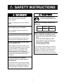
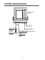
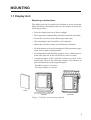
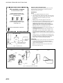
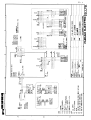
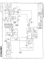
C
Yo u r L o c a l A g e n t/D e a le r
9-52, A shihara-cho,
N ishinom iya, Japan
Te l e p h o n e :
Te l e f a x :
0 7 9 8 -6 5 -2 111
0798-65-4200
A ll rig h ts re s e rv e d .
Printed in Japan
PU B. N o. IM E-23620-J
(H IM A )
FCV-600L
FIRST
EDITIO N
J
:
:
FEB.
O C T.
1998
19, 2001
SAFETY INSTRUCTIONS
CAUTION
WARNING
Ground the equipment to
prevent mutual interference.
Do not open the cover unless totally
familiar with electrical circuits and
service manual.
Improper handling can result in electrical
shock.
Observe the following compass safe
distances:
Turn off the power at the switchboard
before beginning the installation.
Display
Unit
Fire or electrical shock can result if the
power is left on.
Standard
Steering
0.8m
0.6m
When handling the transducer cable,
keep in mind the following points.
. Keep the cable away from oil and
fuel.
. Keep the cable away from the
place where it may be damaged
during the installation.
. Do not paint the cable.
Do not install the equipment where it
may get wet from rain or water splash.
Water in the equipment can result in fire,
electrical shock or equipment damage.
Be sure no water leaks in at the transducer installation site.
Water leakage can sink the vessel. Also
confirm that the transducer will not loosen
by ship's vibration. The installer of the
equipment is solely responsible for the
proper installation of the equipment.
FURUNO will assume no responsibility for
any damage associated with improper
installation.
The sheath of the transducer cable is
made of chlorophrene rubber (or vinyl
chloride). Therefore, do not paint the
sheath with organic liquid (such as
toluene) since it may harm the sheath.
Be sure that the power supply is
compatible with the voltage rating of
the equipment.
Connection of an incorrect power supply
can cause fire or equipment damage. The
voltage rating of the equipment appears
on the label above the power connector.
i
i
TABLE OF CONTENTS
EQUIPMENT LISTS ............................................................................................. iii
SYSTEM CONFIGURATION ................................................................................ iv
MOUNTING
1.1 Display Unit..................................................................................................................... 1
1.2 Thru-hull Mount Transducer 520-5PSD, 520-5MSD ........................................................ 3
1.3 Transom Mount Transducer 520-5PWD,
Optional Transom Mount Triducer 520ST-PWD ............................................................ 6
1.4 Inside-hull Mount Transducer 520-5PSD, 520-5MSD...................................................... 8
1.5 Optional Water Temperature/Speed Sensors .................................................................11
1.6 Optional Water Temperature Sensors ........................................................................... 12
1.7 Optional Triducer 524ST-MSD, 525ST-MSD ................................................................. 14
WIRING
2.1 Wiring ........................................................................................................................... 15
2.2 Connection of Optional Sensors.................................................................................... 17
2.3 Optional 50 kHz and 200 kHz Transducers ................................................................... 19
EXTERNAL EQUIPMENT SETUP
3.1 External Equipment Setup ............................................................................................ 19
APPENDIX TRIDUCER 525ST-PWC/PWD ....................................................AP-1
PACKING LIST .................................................................................................. A-1
OUTLINE DRAWINGS ...................................................................................... D-1
INTERCONNECTION DIAGRAM...................................................................... S-1
SCHEMATIC DIAGRAMS ................................................................................. S-2
ii
EQUIPMENT LISTS
Standard Supply
No.
Name
Type
Code No.
Qty
1
Display Unit CV-600L
2
Installation
Materials
CP02-06000
000-015-398
1 set
3
Spare Parts
SP02-03800
004-399-110
1 set
520-5PSD
000-015-125
520-5MSD
000-015-127
520-5PWD
000-015-126
4
Transducer
Remarks
1
Includes power cable
Inside-hull
Select
Inside-hull, w/8 m cable
one
Transom mount, w/8 m cable
Optional Supply
No.
Name
1
Rectifier
2
Cable Assy.
3
Cable Assy.
4
5
Triducer
Temperature
Sensor
Type
Code No.
Remarks
MJ-A6SPF0012-050
000-134-424
6P-6P, 5 m
MJ-A6SPF0012-100
000-133-817
6P-6P, 10 m
MJ-A6SPF0011-050
000-132-244
6P-4P, 5 m
MJ-A6SPF0011-100
000-132-336
6P-4P, 10 m
524ST-MSD
000-015-224
525ST-MSD
000-015-263
520ST-PWD
000-015-128
525ST-PWD
000-015-261
T-02MTB
000-040-026
With 8 m cable, transom mount
T-02MSB
000-040-040
Thru-hull type
T-03MSB
000-040-027
With 8 m cable, thru-hull type
ST-02MSB
000-137-986
Thru-hull type
ST-02PSB
000-137-987
With 8 m cable, thru-hull type
PR-62
6
ST Sensor
7
Inside Hull
Kit S
22S0191-0
000-802-598
8
Converter
Connector
02S4093
000-134-901
Transducer of AIRMAR
CORP.
9
Converter
Connector
02S4147
000-141-082
Water temperature/speed
sensor
10
Converter
Connector
02S4167
000-142-503
Extends standard transducer
cable 10m.
iii
SYSTEM CONFIGURATION
DISPLAY UNIT
CV-600L
Ship’s mains
12-24 VDC
TRANSDUCER
Standard supply
520-5PSD
520-5MSD
520-5PWD
Optional supply
(triducer)
524ST-MSD
520ST-PWD
External equipment
(GPS navigator, etc.)
SPEED, TEMPERATURE SENSOR (option)
Speed/temperature sensor
ST-02MSB
ST-02PSB
Temperature sensor
T-02MTB
T-02MSB
T-03MSB
iv
MOUNTING
1.1 Display Unit
Mounting considerations
The display unit can be installed on a tabletop or on the overhead.
When selecting a mounting location for the display unit keep the
following in mind:
• Keep the display unit out of direct sunlight.
• The temperature and humidity should be moderate and stable.
• Locate the unit away from exhaust pipes and vents.
• The mounting location should be well ventilated.
• Mount the unit where shock and vibration are minimal.
• Keep the unit away from electromagnetic field-generating equipment such as motors and generators.
• For maintenance and checking purposes, leave sufficient space
at the sides and rear of the unit and leave slack in cables.
• A magnetcompass will be affected if placed too close to the
display unit. Observe the following compass safe distances to
prevent disturbance to the magnetcompass:
Standard compass: 0.8 meters
Steering compass: 0.6 meters
Cover
Tabletop
Overhead
Figure 1-1 Display unit mounting methods
1
Removing cover
While pressing the center of the cover with your thumbs as illustrated, pull the cover towards you to remove it.
Mounting procedure
Figure 1-2 How to set the display unit to the hanger
2
1.2 Thru-hull Mount Transducer 520-5PSD, 520-5MSD
Transducer mounting location
This type of mounting provides the best performance of all, since
the transducer protrudes from the hull and the effect of air bubbles
and turbulence near the hull skin is reduced. When the boat has a
keel, the transducer should be at least 30 cm away from it. Typical
thru-hull mountings are shown in the figure on the next page.
The performance of this sounder is directly related to the mounting location of the transducer, especially for high-speed cruising.
The installation should be planned in advance, keeping the standard cable length (8 m) and the following factors in mind:
• Air bubbles and turbulence caused by movement of the boat
seriously degrade the sounding capability of the transducer. The
transducer should, therefore, be located in a position where water flow is the smoothest. Noise from the propellers also adversely affects performance and the transducer should not be
mounted nearby. The lifting strakes are notorious for creating
acoustic noise, and these must be avoided by keeping the transducer inboard of them.
• The transducer must always remain submerged, even when the
boat is rolling, pitching or up on a plane at high speed.
• A practical choice would be somewhere between 1/3 and 1/2 of
the boat’s length from the stern. For planing hulls, a practical
location is generally rather far astern, so that the transducer is
always in water regardless of the planing attitude.
Transducer outline drawings
22
24
120
120
30
All dimensions 28
in millimeters
Ship's
bow
68
68
520-5PSD
87
520-5MSD
Figure 1-3 Dimensions of transducers 520-5PSD, 520-5MSD
3
Acceptable transducer mounting locations
Deep-V hull
• Position 1/2 to 1/3 length of the hull from stern
• 15 to 30 cm off center line (inside first lifting strakes).
Figure 1-4 Transducer mounting location on deep-V hull
High speed V-planing hull
• Within the wetted bottom area
• Deadrise angle within 15°
Figure 1-5 Transducer mounting location on high speed
V-planing hull
Typical thru-hull mount transducer installations
Fairing block
Flat washer
Rubber washer
Hull
bottom
Hull
bottom
Deep-V Hull
Flat Hull
Figure 1-6 Typical thru-hull mount transducer installations
4
Procedure for installing the thru-hull mount
transducer
1. With the boat hauled out of the water, mark the location selected for mounting the transducer on the bottom of the hull.
2. If the hull is not level within 15° in any direction, fairing blocks
made out of teak should be used between the transducer and
hull, both inside and outside, to keep the transducer face parallel with the water line. Fabricate the fairing block as shown
below and make the entire surface as smooth as possible to
provide an undisturbed flow of water around the transducer.
The fairing block should be smaller than the transducer itself
to provide a channel to divert turbulent water around the sides
of the transducer rather than over its face.
Hole for
stuffing tube
BOW
Upper
half
Lower
half
Saw along slope of hull.
Figure 1-7 Construction of fairing block
3. Drill a hole just large enough to pass the threaded stuffing tube
of the transducer through the hull, making sure it is drilled vertically.
4. Apply a sufficient amount of high quality caulking compound
to the top surface of the transducer, around the threads of the
stuffing tube and inside the mounting hole (and fairing blocks
if used) to ensure watertight mounting.
5. Mount the transducer and fairing blocks and tighten the locking nuts. Be sure that the transducer is properly oriented and its
working face is parallel to the waterline.
Note: Do not over-stress the stuffing tube and locking nuts through
excessive tightening, since the wood block will swell when the
boat is placed in the water. It is suggested that the nut be tightened
lightly at installation and retightened several days after the boat
has been launched.
5
1.3 Transom Mount Transducer 520-5PWD,
Optional Transom Mount Triducer 520ST-PWD
This type of mounting is very commonly employed, usually on
relatively small I/O or outboard boats. Do not use this method on
an inboard motor boat because turbulence is created by the propeller ahead of the transducer.
There are two methods of installation: flush with hull (for flat hulls)
and projecting from hull (for deep V-hulls).
D
D>50 cm
Flat Hull
Deep V-hull
Figure 1-8 Transom mount transducer mounting locations
Installing the transom mount transducer flush with
hull (for flat hulls)
A suitable mounting location is at least 50 cm away from the engine and where the water flow is smooth.
1. Drill four pilot holes in the mounting location.
2. Attach the transducer to the bracket with tapping screws (supplied).
3. Adjust the transducer position so the transducer faces right to
the seabed.
Note: If necessary, to improve water flow and minimize air
bubbles staying on the transducer face, incline the transducer
about 5° at the rear. This may require a certain amount of
experimentation for fine tuning at high cruising speeds.
4. Fill the gap between the wedge front of the transducer and transom with epoxy material to eliminate any air spaces.
6
M5 x 20
M5 x 20
5°
Tape
No. 1 M5 x 14
Figure 1-9 Transom mount transducer, mounting flush with hull
Installing the transom mount transducer projecting
from hull (for deep-V hulls)
This method is employed on deep-V hulls and provides good performance because the effects of air bubbles are minimal. Install
the transducer parallel with water surface; not flush with hull. If
the boat is placed on a trailer care must be taken not to damage the
transducer when the boat is hauled out of the water and put on the
trailer.
M5 x 20
M5 x 20
No. 2
M5 x 14
Figure 1-10 Transom mount transducer, projecting from hull
Transducer preparation
Before putting the boat in water, wipe the face of the transducer
thoroughly with a detergent liquid soap. This will lessen the time
necessary for the transducer to have good contact with the water.
Otherwise the time required for complete “saturation” will be
lengthened and performance will be reduced.
Do not paint the transducer. Performance will be affected.
7
1.4 Inside-hull Mount Transducer 520-5PSD, 520-5MSD
Necessary tools
You will need the following tools:
• Sandpaper (#100)
• Silicone sealant
• Silicone grease
Remarks on installation
• Turn off the engine and anchor the boat while installing the equipment.
• Install the transducer in the engine room.
Selecting the mounting location
Keep the following points in mind when selecting a mounting location:
• The mounting location should be where the hull is of singlehull thickness and is void of air or flotation materials other than
solid fiberglass between the transducer face and the water.
• Do not place the transducer over hull struts or ribs which run
under the hull.
• Avoid a location where the rising angle of the hull exceeds 15°,
to minimize the effect of the boat’s rolling.
• You will finalize the mounting location through some trial and
error. The procedure for this is shown later.
Center line
50cm
50cm
1/2
1/3
15cm
15cm
Mounting location
for transducer
Figure 1-11 Inside-hull transducer mounting location
8
Attaching the transducer
1. Clean the transducer face to remove any foreign material.
Lightly roughen the transducer face with #100 sandpaper. Also,
roughen the inside of the hull where the transducer is to be
mounted.
2. Warm the silicone sealant to 40°C before usage to soften it.
Coat the transducer face and mounting location with silicone
sealant.
Transducer face
Silicone sealant
Figure 1-12 Coating the transducer face with silicone sealant
3. Press the transducer firmly down on the hull and gently twist it
back and forth to remove any air which may be trapped in the
silicone sealant.
Squeeze out
air bubbles.
Hull
Silicone
sealant
Figure 1-13 Attaching transducer to hull with silicone sealant
9
Checking the installation
1. Connect the battery to the display unit as shown on page 15.
2. Turn on the display unit.
3. Press the MODE key to select NORMAL (if it is not already
selected) and press the MENU ESC key.
4. Press the AUTO key to select OFF (if it is not already selected)
and press the MENU ESC key.
5. Press the GAIN+ key to set the gain to “5” and press the MENU
ESC key.
6. Press the RANGE+ key to set the range to 30 feet and press the
MENU ESC key.
7. If the bottom is displayed in red and the depth indication appears the mounting location is suitable. You can leave the transducer in position.
--.-°C
---kt
50k
0.0
0
2
Transmission
line
4
6
Reddishbrown
Bottom
8
Depth
6.5
10
Figure 1-14 Sounder display
8. If the bottom is not displayed in red, the mounting location is
unsuitable. Do the following:
1) Press the POWER key to turn off the power.
2) Gently dismount the transducer with a piece of wood.
3) Reattach the transducer elsewhere as shown in “Attaching
the transducer.”
4) Check the installation again.
Final preparation
Support the transducer with a piece of wood to keep it in place
while it is drying. Let the transducer dry 24–72 hours.
10
1.5 Optional Water Temperature/Speed Sensors
Through-hull mount water temperature/speed sensor
ST-02MSB, ST-02PSB
Select a suitable mounting location considering the following:
• Select a mid-boat flat position. The sensor does not have to be
installed perfectly perpendicular. The sensor must not be damaged in dry-docking operation.
• Select a place apart from equipment generating heat.
• Select a place in the forward direction viewing from the drain
hole, to allow for circulation of cooling water.
• Select a place free from vibration.
1. Dry-dock the boat.
2. Make a hole of approx. 51 mm diameter.
3. Unfasten locknut and remove the sensor section.
4. Apply high-grade sealant to the flange of the sensor.
5. Pass the sensor casing through the hole.
6. Face the notch on the sensor toward boat’s bow and tighten the
flange.
7. Set the sensor section to the sensor casing and tighten the locknut.
8. Launch the boat and check for water leakage around the sensor.
Locknut
Face "notch"
toward bow.
51
Flange nut
Coat with
silicone sealant.
123
Brim
ø77
Figure 1-15 Water temperature/speed sensor ST-02MSB,
ST-02PSB
11
1.6 Optional Water Temperature Sensors
Transom mount water temperature sensor T-02MTB
• Fix the cable at a convenient location with cable clamp.
• When the cable is led in through the transom board, make a
hole of approx. 17 mm diameter to pass the connector. After
passing the cable, fill the hole with a sealing compound.
D
D>50 cm
M5 x 20
Mount sensor
flush with hull bottom.
Figure 1-16 How to install transom mount water temperature
sensor T-02MTB
12
Thru-hull mount water temperature sensor
T-02MSB, T-03MSB
• Select a mid-boat flat position. The sensor does not have to be
installed perfectly perpendicular. The sensor must not be damaged in dry-docking operation.
• Select a place apart from equipment generating heat.
• Select a place in the forward direction viewing from the drain
hole, to allow for circulation of cooling water.
• Select a place free from vibration.
T-02MSB
T-03MSB
Sensor Holder
Sensor
cable
Locknut
Locknut
Washer
Gasket
Locknut
Washer
Gasket
φ25 mm
φ21 mm
Coat with
sealant.
Mounting procedure
1. Drill a hole of 21 mm in diameter in
the mounting location.
2. Pass the sensor cable through the
hole.
3. Pass gasket, washer and locknut
onto cable in that order.
4. Coat the sensor flange with high
quality sealant and then fasten the
sensor with the locknut.
(Torque: max. 59N·m)
5. Launch the boat to check for water
leakage around the sensor.
Coat with
sealant.
Holder Guide
Plate thickness
within 25 mm
Mounting procedure
1. Drill a hole of 25 mm in diameter in the mounting
location.
2. Coat holder guide with high quality sealant, and
pass gasket, washer and locknut onto holder
guide in that order and then tighten the locknut.
3. Set the sensor holder to the holder guide from
inside the boat and then tighten the locknut.
4. Launch the boat to check for water leakage
around the sensor.
Figure 1-17 Thru-hull mount water temperature sensors
T-02MSB, T-03MSB
13
1.7 Optional Triducer 524ST-MSD, 525ST-MSD
The triducer is designed for thru-hull mounting.
Mounting considerations
When selecting a mounting location keep the following points in
mind:
• Air bubbles and turbulence caused by movement of the boat
seriously degrade the sounding capability of the transducer. The
transducer should, therefore, be located in a position where water flow is the smoothest. Noise from the propellers also adversely affects performance and the transducer should not be
mounted nearby. The lifting strakes are notorious for creating
acoustic noise, and these must be avoided by keeping the transducer inboard of them.
• The transducer must always remain submerged, even when the
boat is rolling, pitching or up on a plane at high speed.
• A practical choice would be somewhere between 1/3 and 1/2 of
the boat’s length from the stern. For planing hulls, a practical
location is generally rather far astern, so that the transducer is
always in water regardless of the planing attitude.
∅79 mm
133 mm
2.00"-12 UN
threads
7 mm
∅51 mm
27 mm
140 mm
Figure 1-18 Dimensions of triducer 524ST-MSD
14
WIRING
2.1 Wiring
All wiring are terminated at the rear of the display unit.
DISPLAY UNIT
Earth terminal
Ext.
equip
Black
White
Shield
BATTERY
TRANSDUCER
Figure 2-1 Display unit, rear view
Power cable
Connect the power cable to the power connector. Connect the leads
to the battery (12 or 24 VDC); white to plus(+) terminal and black
to minus(-) terminal.
Cable connector
Power cable
w/fuse (3A)
Lead wire
Black
White
BATTERY
Figure 2-2 Connecting the power cable to the battery
15
Transducer, optional triducer
Connect the transducer cable to the XDR connector.
Ground
Connect the ground wire (KIV 2.0sq, 2m, supplied) to ship’s ground
to prevent interference to the picture. Shorten the ground wire as
much as possible. For FRP vessels, install a ground plate that measures about 20 cm by 30 cm on the outside of the hull bottom to
provide a ground point.
CAUTION
Ground the equipment
to prevent mutual
interference.
Note: Use a “closed” lug to make the ground connection at the
).
display unit. Do not use an “open-type” lug (
Attaching EMI cores
Attach EMI cores to the power cable and transducer cable to prevent noise.
1. Tape the power cable and transducer cable where the EMI core
is to be attached, to fix the core.
2. Attach cores where tape is placed on respective cables.
EMI core
Figure 2-3 How to attach EMI cores
16
2.2 Connection of Optional Sensors
Water temperature sensor
Connect the transducer cable to the XDR connector. Connect the
water temperature sensor (option) or water temperature/speed sensor (option) to the XDR connector with the converter connector
(Type : 02S4147 , Code No. : 000-141-082,option).
MJ-A6SRMD
MJ-A10SPF
SHIELD
TEMP
TEMP0V
NC
NC
NC
1
4
7
3
2
5
6
8
9
10
1
2
3
4
5
6
MJ-A10SRMD
NC
NC
NC
NC
NC
NC
NC
XDR+
XDR SHIELD
XDR-
1
2
3
4
5
6
7
8
9
10
NC
TEMP
TEMP0V
NC
NC
NC
NC
XDR+
XDR SHIELD
XDR-
Figure 2-4 Connection of water temperature speed sensor
Water temperature/speed sensor
MJ-A6SRMD
SHIELD
TEMP
TEMP0V/SPD0V
SPD
+V
NC
MJ-A10SPF
1
2
3
4
5
6
MJ-A10SRMD
1
2
3
NC
NC
NC
NC
NC
NC
NC
XDR+
XDR SHIELD
XDR-
4
7
3
1
2
5
6
8
9
10
TEMP
TEMP0V
SPD0V/ SHIELD
SPD
+12.7V
NC
NC
XDR+
XDR SHIELD
XDR-
4
5
6
7
8
9
10
Figure 2-5 Connection of water temperature/speed sensor
17
Connect to XDR connector
at rear of display unit
MJ-A10SPF
MJ-A6SRMD
MJ-A10SRMD
Tape connector with
self-vulcanizing tape
and then vinyl tape
to waterproof
connector. Bind tape
end with cable tie.
Water temp., water temp/speed
sensor connector
Transducer connector
Figure 2-6 Connection of transducer, water temperature sensor,
water temperature/speed sensor
NMEA data sentences
18
Input/Output
Data Sentence
INPUT: L/L, Course, Speed,
Waypoint Range/Bearing,
Water Temperature,
Cross-Track Error
RMA, RMB, RMC,
BWC, GLL, MTW,
VTG, VHW, XTE
OUTPUT: Depth, Water
Temperature, Speed
Output every 2 sec.
DBT (Ver. 1.5)
DPT (Ver. 2.0)
MTW, VHW
EXTERNAL EQUIPMENT SETUP
This chapter shows you how to set up the FCV-600L when external equipment is connected. If a water temperature/speed sensor is
installed, you should complete this section with the boat in the
water and running, to confirm speed/water temperature readout.
Display the system menus as shown below, and then follow appropriate procedure(s) on the next page. Finish by resetting the power
and checking for proper display of data.
3.1 External Equipment Setup
Displaying the system menu 1, system menu 2
1. Press the MENU ESC key.
2. Press ▼ to select GO TO SYSTEM MENU.
3. Press s once to display the System menu 1; press it twice to
display the System menu 2. You can switch between these
menus with t and swhen the MENU line is selected.
SYSTEM MENU 1
MENU 1 2 3
DEPTH UNIT m ft fa pb
SPEED UNIT kt MPH km/h
TEMP UNIT ° C ° F
ZOOM MARK OFF ON
F/A LEVEL WEAK MED STRG
TEMP GRAPH
OFF ON
LANG English
DISP SEL GRA1 GRA2
DRAFT
0.0 [-20~+20]
: To select item
: To set condition
ESC : ESCAPE
SYSTEM MENU 2
MENU
1
2
3
at
NAV DSP OFF L/L R/B CSE
"MENU 1"
NMEA Ver1.5 Ver2.0
BEARING TRUE MAG
SPD SEL OFF
OWN NMEA
at
TMP SEL OFF
OWN NMEA
"MENU 2"
SPD ADJ
0 %
[-50~+50]
TMP ADJ 0.0
°F [-20~+20]
(ADJUSTABLE OWN SENSOR ONLY)
OWN SENSOR OWN SENSOR
TEMPERATURE
SPEED
– –. – kt
– –. – °F
: To select item
: To set condition
ESC : ESCAPE
Figure 3-1 System menu 1, System menu 2
4. Follow appropriate procedure(s) on the next page.
19
Draft setup
1. At the System menu 1, press ▼ to select DRAFT.
2. Press t or s to set draft. For example, if the depth readout is
5 feet lower than actnal depth, enter +5 feet.
Navigator setup
1. At the System menu 2, press ▼ to select NMEA.
2. Press t or s to select NMEA input format of navigator; Ver.
1.5 or Ver. 2.0. (If you are unsure of the version no., try both
and select the one which successfully inputs nav data to the
sounder.)
3. To display nav data on the sounder displays, press ▲ to select
NAV DSP.
4. Press t or s to select which nav data to display; L/L (Position), R/B (Range and Bearing to a Waypoint), or CSE (Course).
Speed data setup
1. At the System menu 2, press ▼ to select SPD SEL.
2. Press t or s to select source of speed data; OWN (speed
sensor) or NMEA.
3. For speed sensor-equipped sets, you may offset the speed readout if it is wrong. Run the boat at various speeds and watch the
speed readout at the bottom of the screen. If it is unreasonably
wrong, press ▼ to select SPD ADJ.
4. Press t or s to correct speed readout. For example, if the
readout is 10% lower than actual speed, enter +10.
Water temperature data setup
1. At the System menu 2, press ▼ to select TMP SEL.
2. Press t or s to to select source of water temperature data;
OWN (water temperature sensor) or NMEA.
3. For water temperature sensor-equipped sets, you may offset
the water temperature readout if it is wrong. Watch the water
temperature readout at the bottom of the screen. If it is unreasonably wrong, press ▼ to select TMP ADJ.
4. Press t or s to correct water temperature readout. For example, if the readout is 2° higher than actual temperature, enter
-2°.
5. To display a water temperature graph (shows present water temperature), press ▲ to select MENU and press t to select 1.
The System menu 1 appears.
6. Press ▼ to select TEMP GRAPH.
7. Press s to select ON.
20
Confirming indications
1. Reset the power.
2. Confirm that appropriate data appears on the display.
Speed
Water temperature
Nav data (position)
22.6°C 12kt
35°15.000’N
135°07.500’E
200k
0.0
0
30
Water temperature
scale
Water temperature
marker (orange)
20
20
10
0
49.6
40
60
80
Figure 3-2 Location of speed, water temperature and nav data
indications
21
APPENDIX
TRIDUCER 525ST-PWC/PWD
This appendix provides a copy of the installation instructions for AIRMAR triducer. If you
loose the original supplied with the triducer, use this appendix.
INSTALLATION INSTRUCTIONS
Transom Mount Transducer or TRIDUCER
Multisensor with Integral Release Bracket
®
Model P66
U.S. Patents: 4,555,938; 4,644,787; 5,606,253; Des. 334,335
Canadian Patent 1,233,341
IMPORTANT Please read the instructions completely before
proceeding with the installation. These directions supersede
any other instructions in your instrument manual if they differ.
Applications
Pre-test for Speed and Temperature
• Powerboats with outboard, inboard, inboard/outboard, or jet drive.
Not recommended for boats with large or twin screw inboard motor.
• Bracket protects the sensor form frontal impact only
Connect the sensor to the instrument and spin the paddlewheel. Check
for a speed reading and the approximate air temperature. If there is no
reading, return the sensor to your place of purchase.
Mounting Location
• Good operation up to 44kn (50MPH)
To ensure the best performance, the sensor must be submerged in
aeration-free and turbulence-free water. Mount the sensor close to the
centerline of the boat. On slower heavier displacement hulls, positioning
it farther from the centerline is acceptable.
• Orients the sound beam vertically on hulls with a
deadrise angle up to 30°
• Adjusts to transom angles from 2-22°
Allow adequate space above the bracket for it to release and rotate the
sensor upward (see Figure 1).
Tools and Materials Needed
Scissors
Masking tape
Safety goggles
Dust mask
Electric drill
Drill bit for:
Bracket holes
4mm, #23, or 9/64”
Fiberglass hull
chamfer bit (preferred), 6mm, or 1/4”
Transom hole
19mm or 3/4” (optional)
Cable clamp holes
3mm or 1/8”
Screwdrivers
Straight edge
Marine sealant
Pencil
Zip-ties
Water-based antifouling paint (mandatory in salt water).
Caution: Do not mount the sensor in an area of turbulence or bubbles:
Near water intake or discharge openings;
Behind strakes, struts, fittings, or hull irregularities;
Behind eroding paint (an indication of turbulence).
Caution: Avoid mounting the sensor where the boat may be supported
during trailering, launching, hauling, and storage.
• Single drive boat—Mount on the starboard side at least 75mm
(3”) beyond the swing radius of the propeller (see Figure 2).
• Twin drive boat—Mount between the drives.
Height without
speed sensor
191mm (7-1/2")
Height with
speed sensor
213mm (8-1/2")
height
Figure 1. Height required at mounting location
75 mm(3")
minimum beyond
swing radius
Figure 2. Mounting location on single drive boat
AP-1
APPENDIX TRIDUCER 525ST-PWC/PWD
Caution: Never Use Solvents!
Cleaners, gasoline, paint, sealants, and other products may contain
strong solvents such as acetone which can attack many plastics
dramatically reducing their strength.
P66 Installation template
for starboard side of boat
Installation
Drill at locations labeled "B"
for the following transom angles:
16° through 22°
B
B
B
A
A
A
Bracket
1. Cut out the installation template shown on the left.
2.
At the selected location, position the template, so the arrow at the
bottom is aligned with the bottom edge of the transom. Being sure
the template is parallel to the waterline, tape it in place
(see Figure 3).
Warning: Always wear safety goggles and a dust mask.
Drill at locations labeled "A"
for the following transom angles:
2° through 15°
Align arrow with bottom of transom
3.
Using a 4mm, #23, or 9/64” bit, drill three holes 22mm (7/8”) deep
at the locations indicated. To prevent drilling too deeply, wrap
masking tape around the bit 22mm (7/8”) from the point.
Fiberglass hull—Minimize surface cracking by chamfering the
gelcoat. If a chamfer bit or countersink bit is not available, start
drilling with a 6mm or 1/4” bit to a depth of 1mm (1/16”).
4.
If you know your transom angle—The bracket is designed for a
standard 13° transom angle.
11°-18° angle—No shim is required. Skip to “Adjusting”, step 3.
Other angles—The shim is required. Skip to “Adjusting”, step 2.
If you do not know the transom angle—Temporarily attach the
bracket and sensor to the transom to determine if the plastic shim is
needed.
Align template vertically
5.
deadrise angle
Using the two #10 x 1-1/4” self-tapping screws, temporarily screw
the bracket to the hull. Do not tighten the screws completely at this
time. Follow the instructions for “Attaching the Sensor to the
Bracket”, steps 1-4 before proceeding with “Adjusting”.
slope of hull
Adjusting
parallel to
waterline
1.
Align template arrow with
bottom edge of transom
Using a straight edge, sight the underside of the sensor relative to
the underside of the hull. The stern of the sensor should be
1-3mm (1/16-1/8”) below the bow of the sensor or parallel to the
bottom of the hull (see Figure 5).
Caution: Do not position the bow of the sensor lower than the
stern because aeration will occur.
Figure 3. Template position
Step 1
Step 2
Step 3
latch
pivot
arm (2)
retaining
cover
slot (2)
Figure 4. Attaching the sensor to the bracket
AP-2
Step 4
APPENDIX TRIDUCER 525ST-PWC/PWD
Cable Routing
2°-10° transom angle
11° transom angle
NO SHIM
19°-22° transom angle
shim with
taper down
YES
parallel
shim with
taper up
YES
parallel
YES
angle
reversed
YES
slight
angle
Caution: Never cut the cable or remote the connector; this will void the
warranty.
Warning: Always wear safety goggles and a dust mask.
1.
If a hole must be drilled, choose a location well above the waterline.
Check for obstructions such as trim tabs, pumps, or wiring inside
the hull. Mark the location with a pencil. Drill a hole through the
transom using a 19mm or 3/4” bit (to accommodate the connector).
2.
Route the cable over or through the transom.
3.
On the outside of the hull secure the cable against the transom
using the cable clamps. Position a cable clamp 50mm(2”) above the
bracket and mark the mounting hole with a pencil (see Figure 6).
4.
Position the second cable clamp halfway between the first clamp
and the cable hole. Mark this mounting hole.
5.
If a hole has been drilled in the transom, open the appropriate slot
in the transom cable cover. Position the cover over the cable where
it enters the hull. Mark the two mounting holes.
6.
At each of the marked locations, use a 3mm or 1/8” bit to drill a
hole 10mm (3/8”) deep. The prevent drilling too deeply, wrap
masking tape around the bit 10mm (3/8”) from the point.
7.
Apply marine sealant to the threads of the #6 x 1/2” self-tapping
screw to prevent water from seeping into the transom. If you have
drilled a hole through the transom, apply marine sealant to the
space around the cable where it passes through the transom.
8.
Position the two cable clamps and fasten them in place. If used,
push the cable cover over the cable and screw it in place.
9.
Route the cable to the instrument being careful not to tear the cable
jacket when passing it though the bulkhead(s) and other parts of the
boat. To reduce electrical interference, separate the sensor
cable from other electrical wiring and “noise” sources. Coil any
excess cable and secure it in place with zip-ties to prevent damage.
parallel
12-18° transom angle
NO SHIM
NO
Route the sensor cable over the transom, through a drain hole, or
thorough a new hole drilled in the transom above the waterline.
NO
angle
too steep
Figure 5. Sensor angle adjustment on transom
2.
3.
4.
5.
To adjust the sensor’s angle relative to the hull, use the tapered
plastic shim provided. If the bracket has been temporarily fastened
to the transom, remove it, Key the shim in place on the back of the
bracket.
2°-10° transom angle (stepped transom and jet boats)—Position
the shim with the tapered end down.
19°-22° transom angle (small aluminum and fiberglass boats)—
Position the shim with the tapered end up.
If the bracket has been temporarily fastened to the transom,
remove it. Apply a marine sealant to the threads of the two
#10 x 1-1/4” self tapping screws to prevent water seeping into the
transom. Screw the bracket to the hull. Do not tighten the screws
completely at this time.
10. Refer to your echosounder owner’s manual to connect the sensor
to the instrument.
Repeat step 1 to ensure that the angle of the sensor is correct.
Caution: Do not position the sensor farther into the water than
necessary to avoid increasing drag, spray, and water noise and
reducing boat speed.
cable cover
Using the vertical adjustment space on the bracket slots, slide the
sensor up or down to provide a projection of 3mm (1/8”). Tighten
the screws (see Figure 6).
cable clamp
Attaching the Sensor to the Bracket
1.
If the retaining cover near the top of the bracket is closed, open it by
depressing the latch and rotating the cover downward
(see Figure 4).
2.
Insert the sensor’s pivot arms into the slots near the top of the
bracket.
3.
Maintain pressure until the pivot arms click into place.
4.
Rotate the sensor downward until the bottom snaps into the
bracket.
5.
Close the retaining cover to prevent the accidental release of the
sensor when the boat is underway.
50mm (2")
Hull projection
3mm (1/8")
Figure 6. Vertical adjustment and cable routing
AP-3