1
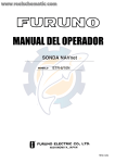
OPERATOR'S MANUAL
Bottom Discrimination Sounder
Model
BBDS1
www.furuno.com
IMPORTANT NOTICES
General
• This manual has been authored with simplified grammar, to meet the needs of international
users.
• The operator of this equipment must read and follow the descriptions in this manual. Wrong
oper-ation or maintenance can cancel the warranty or cause injury.
• Do not copy any part of this manual without written permission from FURUNO.
• If this manual is lost or worn, contact your dealer about replacement.
• The contents of this manual and equipment specifications can change without notice.
• The example screens (or illustrations) shown in this manual can be different from the screens you
see on your display. The screens you see depend on your system configuration and equipment
settings.
• Save this manual for future reference.
• Any modification of the equipment (including software) by persons not authorized by FURUNO will cancel the warranty.
• All brand and product names are trademarks, registered trademarks or service marks of their
re-spective holders.
• Microsoft, Windows, Windows Vista and Outlook are registered trademarks or trademarks of
the Microsoft Corporation in the United States and other countries.
How to discard this product
Discard this product according to local regulations for the disposal of industrial waste. For disposal
in the USA, see the homepage of the Electronics Industries Alliance (http://www.eiae.org/) for the
correct method of disposal.
How to discard a used battery
Some FURUNO products have a battery(ies). To see if your product has a battery, see the chapter
on Maintenance. Follow the instructions below if a battery is used. Tape the + and - terminals of
battery before disposal to prevent fire, heat generation caused by short circuit.
In the European Union
The crossed-out trash can symbol indicates that all types of batteries
must not be discarded in standard trash, or at a trash site. Take the
used batteries to a battery collection site according to your national legislation and the Batteries Directive 2006/66/EU.
Cd
In the USA
The Mobius loop symbol (three chasing arrows) indicates that Ni-Cd and
lead-acid rechargeable batteries must be recycled. Take the used batteries to a battery collection site according to local laws.
Ni-Cd
Pb
In the other countries
There are no international standards for the battery recycle symbol. The number of symbols can
increase when the other countries make their own recycle symbols in the future.
i
SAFETY INSTRUCTIONS
The user and installer must read the appropriate safety instructions before attempting to install
or operate the equipment.
WARNING
Indicates a potentially hazardous situation which, if not avoided,
could result in death or serious injury.
CAUTION
Indicates a potentially hazardous situation which, if not avoided,
may result in minor or moderate injury.
Warning, Caution
Mandatory Action
Prohibitive Action
Safety instructions for the operator
WARNING
WARNING
Do not open the equipment.
Do not operate the equipment with
wet hands.
Only qualified personnel should work
inside the equipment.
Electrical shock can result.
Do not disassemble or modify the
equipment.
Do not place liquid-filled containers
on the top of the equipment.
Fire, electrical shock or serious injury can
result.
Electrical shock can result.
Turn off the equipment immediately if
it is emitting smoke or fire.
Do not install the equipment
where it may be subjected to rain or
water splash.
Fire or electrical shock can result if the
power is left on.
Fire or electrical shock can result if water
gets inside the equipment.
Turn off the power immediately if water
leaks into the equipment or an object
is dropped inside the equipment.
Use the proper fuse.
WARNING
Use of a wrong fuse can damage the
equipment and may cause fire.
Continued use can cause fire or electrical
shock.
A warning label is attached to the equipment.
Do not remove the label. If a label is missing
or illegible, contact a FURUNO agent or dealer
about replacement.
Turn off the power immediately if you
feel the equipment is acting abnormally.
If the equipment is very warm or is
emitting strange noises turn off the
power immediately and contact your
dealer for advice.
WARNING
To avoid electrical shock,
do not remove cover. No
user-serviceable parts
inside.
ii
Name: Warning Label (1)
Type: 86-003-1011-3
Code No.: 100-236-233-10
SAFETY INSTRUCTIONS
Safety instructions for the installer
WARNING
CAUTION
The transducer cable must be handled
carefully, following the guidelines
below.
Do not open the equipment.
Only qualified personnel should work
inside the equipment.
●
Turn off the power at the main switchboard
before beginning the installation.
●
●
Fire or electrical shock can result if the
power is left on.
Keep fuels and oils away from the
cable.
Locate the cable away from chemicals.
Locate the cable away from locations
where it might be damaged.
Do not turn on the power with the
transducer exposed to air.
Confirm that there is no water leakage at
the transducer and temperature
sensor.
Damage to the transducer may result.
WARNING
Observe the following compass safe
distances to prevent interference to a
magnetic compass:
Water leakage can sink the vessel. Also,
confirm that neither the transducer or
sensor is loosened by vibration. The
installer is solely responsible for the
installation.
Confirm that the power supply voltage
is within the rating of this equipment.
Incorrect voltage will damage the equipment and may cause fire.
iii
Standard
compass
Steering
compass
0.30 m
0.30 m
TABLE OF CONTENTS
FOREWARD ....................................................................................................................v
SYSTEM CONFIGURATION ..........................................................................................vi
EQUIPMENT LIST .........................................................................................................vii
1.
MOUNTING ...............................................................................................................1
1.1 Bottom Discrimination Sounder..................................................................................... 1
1.2 Transducer 520-5PSD, 520-5MSD ............................................................................... 2
1.2.1 Mounting location................................................................................................... 2
1.2.2 Acceptable mounting locations .............................................................................. 3
1.2.3 Installation Procedure ............................................................................................ 3
1.3 Transducer 525-5PWD (transom mount) ...................................................................... 4
1.3.1 Installation for flat hulls .......................................................................................... 5
1.3.2 Installation for deep-V hulls ................................................................................... 5
1.3.3 Transducer preparation ......................................................................................... 6
1.4 Optional Water Temperature Sensor ST-02MSB, ST-02PSB....................................... 6
1.5 Optional Temperature Sensors ..................................................................................... 7
1.5.1 Transom mount temperature sensor T-02MTB ..................................................... 7
1.5.2 Thru-hill temperature sensor T-02MSB, T-03MSB ................................................ 7
1.6 Optional Triducers......................................................................................................... 9
1.6.1 Thru-hull triducer 525STID-MSD ........................................................................... 9
1.6.2 Transom route triducer 525STID-PWD.................................................................. 9
2.
WIRING ...................................................................................................................14
2.1 Connections ................................................................................................................ 14
2.2 Optional Temperature/Speed Sensor, Temperature Sensor. ..................................... 15
2.3 Wiring Optional 1 kW Transducer ............................................................................... 16
3.
INITIAL SETTINGS, OPERATION..........................................................................18
3.1 MODE SW................................................................................................................... 18
3.2 Operation Check (LED)............................................................................................... 19
4.
MAINTENANCE ......................................................................................................20
4.1 Maintenance................................................................................................................ 20
4.2 Replacing the fuse ...................................................................................................... 21
SPECIFICATIONS .....................................................................................................SP-1
PACKING LIST ............................................................................................................ A-1
OUTLINE DRAWING ................................................................................................... D-1
INTERCONNECTION DIAGRAM ................................................................................ S-1
iv
FOREWARD
A Word to the Owner of the BBDS1
Congratulations on your choice of the BBSD1 Bottom Discrimination Sounder. We are confident
you will see why the FURUNO name has become synonymous with quality and reliability.
Since 1948, FURUNO Electric Company has enjoyed an enviable reputation for innovative and
dependable marine electronics equipment. This dedication to excellence is furthered by our extensive global network of agents and dealers.
Your equipment is designed and constructed to meet the rigorous demands of the marine environment. However, no machine can perform its intended function unless properly operated and
maintained. Please carefully read and follow the operation and maintenance procedures set forth
in this manual.
Thank you for considering and purchasing FURUNO.
We would appreciate feedback from you, the end-user, about whether we are achieving our purposes.
Features:
The BBDS1 features the following:
• Onboard bottom discrimination capability to assist with fishing.
• Displays fish icons which allow the user to easily discern the actual size of fish (ACCU-FISHTM).
Caution when operating:
Please keep the following in mind when using the Bottom Discrimination Sounder:
• The BBDS1 is for use with NavNet 3D (MFD8/12/BB) and NavNet TZtouch (TZT9/14).
• Use at a depth of 5 m - 100 m.
• Use a ship speed of 10 kt or less.
• Enter the ship’s draft value via the NavNet 3D/TZtouch.
• To show a consistent display of the actual bottom, set the range display of the fish finder screen
to “auto”.
v
SYSTEM CONFIGURATION
Bottom Discrimination
Sounder BBSD1
NavNet 3D/
TZtouch series
MFD8/12
MFDBB,
TZT9/14
NavNet 3D/
TZtouch series
HUB-101
MFD8/12
MFDBB,
TZT9/14
MFD8/12
MFDBB,
TZT9/14
Rectifier
PR-62
Matching Box
MB-1100
12-24 VDC
100/110/220/230 VAC,
1ø, 50/60 Hz
Transducer
520-5PSD
525-5PWD
520-5MSD
Speed/temperature
sensor
ST-02MSB
ST-02PSB
Triducer
525STID-MSD
525STID-PWD
Temperature
sensor
T-02MTB
T-02MSB
T-03MSB
*: HUB-101 may be connected to 3 sets of MFB8/12/MFDBB
vi
Transducer
50/200-1T
50/200-12M
for
1 kW
transducer
EQUIPMENT LIST
Standard supply
Name
Bottom Discrimination
Sounder
Spare Parts
Installation
Materials
Type
BBDS1
Code No.
Qty
-
1
SP02-05201
CP02-08700
001-007-860
000-017-040
1 set
1 set
Remarks
Fuse
See Packing List
Optional supply
Name
Matching Box
Cable Assy
Type
MB-1100
MOD-Z072-020+
MOD-Z072-100+
525STID-MSD
525STID-PWD
520-5PSD
520-5PWD
520-5MSD
50/200-1T
50/200-12M
ST-02MSB
ST-02PSB
Code No.
000-041-353
000-167-175-10
000-167-177-10
000-011-783
000-011-784
000-015-204
000-146-966
000-015-212
000-015-170
000-015-171
000-137-986
000-137-987
Remarks
For 1 kW
2 m LAN cable
10 m LAN cable
Thru-hull mount, metal
Transom mount, resin
Thru-hull mount, resin
Transom mount, resin
Thru-hull mount, metal
10 m, 1 kW
10 m, 1 kW
Thru-hull mount, metal
Thru-hull mount, resin
Cable Assy.
T-02MTB
T-02MSB
T-03MSB
02S4147
000-040-026
000-040-040
000-040-027
000-141-082
Rectifier
PR-62
000-013-484
000-013-485
000-013-486
000-013-487
Transom mount
Thru-hull mount
Thru-hull mount
For Speed/Temp sensor, Temp. sensor
100 V AC
110 V AC
220 V AC
230 V AC
Triducer
Transducer
Speed/
Temperature
sensor
Temperature
sensor
vii
1.
MOUNTING
1.1
Bottom Discrimination Sounder
CAUTION
Do not apply paint, rust protection, etc, to coated surface parts of the unit.
These may damage the coated surface areas.
Be especially careful not to apply chemicals to the coated connectors.
The Bottom Discrimination Sounder can be installed on a desktop, deck or on a bulkhead. When
selecting a mounting location for the Bottom Discrimination Sounder, keep the following in mind:
• Locate the unit away from areas where rain and splash can occur.
• The temperature and humidity should be moderate and stable.
• Locate the unit away from exhaust pipes and vents.
• Locate the unit where shock and vibration are minimal.
• The mounting location should be well ventilated.
• Keep the unit away from electromagnetic field-generating equipment such as motors and generators.
• Leave slack in cables for maintenance and servicing ease.
• A magnetic compass will be affected if the unit is placed too close to it. Observe the compass
safe distances noted in the safety instructions to prevent disturbance to the magnetic compass.
(0
0.04”)
(8.6”)
(1.7”)
(5.7”
(0.5”)
(0.2”)
.1
”)
• Fasten the Bottom Discrimination Sounder to the mounting location with four self-tapping
screws (4×20, supplied). Fasten as specified by the drawing at the end of this book. If fastening
to an upright wall or bulkhead, mount the unit vertically, not sideways.
(3.3”)
(2 - 0.2”)
(3.5”)
(9.0” 0.04”)
(10.0”)
(2.8”)
(2.8”)
1
1. MOUNTING
1.2
Transducer 520-5PSD, 520-5MSD
1.2.1
Mounting location
The performance of this sounder is directly related to the mounting location of the transducer, especially for high-speed cruising. The installation should be planned in advance, keeping the standard cable length and the following factors in mind:
• When the boat has a keel, the transducer should be at least 15-30 cm (5.9” - 11.8”) away from
it. Typical thru-hull mountings are shown in the figure on the next page.
• Air bubbles and turbulence caused by movement of the boat seriously degrade the sounding
capability of the transducer. The transducer should, therefore, be located in a position where
water flow is the smoothest. Noise from the propellers also adversely affects performance and
the transducer should not be mounted nearby. The lifting strakes are notorious for creating
acoustic noise, and these must be avoided by keeping the transducer inboard of them.
• The transducer must always remain submerged, even when the boat is rolling, pitching or up
on a plane at high speed.
• A practical choice would be somewhere between 1/3 and 1/2 of the boat's length from the stern.
For planing hulls, a practical location is generally rather far astern, so that the transducer is always in water regardless of the planing attitude
24 mm (0.9”)
22 mm (0.9”)
120 mm (4.7”)
120 mm (4.7”)
28 mm (1.1”)
30 mm (1.2”)
68 mm (2.7”)
Ship’s bow
87 mm (3.4”)
68 mm (2.7”)
520-5PSD
520-5MSD
2
1. MOUNTING
1.2.2
Acceptable mounting locations
Deep V-hull
* Position 1/2 to 1/3 length of the hull from stern.
* 15-30 cm from keel line (inside first lifting strakes).
High speed V-planning hull
* Within the submerged bottom area
* Deadrise angle within 15°
1.2.3
Installation Procedure
1. With the boat hauled out of the water, mark the location selected for mounting the transducer
on the bottom of the hull. If the hull is not level within 15 degrees in any direction, fairing blocks
made out of teak should be used between the transducer and hull, both inside and outside, to
keep the transducer face parallel with the water line. Fabricate the fairing block as shown be-
3
1. MOUNTING
low and make the entire surface as smooth as possible to provide an undisturbed flow of water
around the transducer.
The fairing block should be smaller than the transducer itself to provide a channel to divert
turbulent water around the sides of the transducer rather than over its face.
BOW
Hole for stuffing tube
Upper half
Lower half
Saw along slope of hull
2. Drill a hole just large enough to pass the threaded stuffing tube of the transducer through the
hull, making sure it is drilled vertically.
3. Apply a sufficient amount of high quality caulking compound to the top surface of the transducer, around the threads of the stuffing tube and inside the mounting hole (and fairing blocks
if used) to ensure watertight mounting.
4. Mount the transducer and fairing blocks and tighten the locking nuts. Be sure that the transducer is properly oriented and its working face is parallel to the water line.
Flat washer
Rubber
washer
Fairing block
Hull bottom
Hull bottom
Deep-V Hull
Flat Hull
Note: Do not over-stress the stuffing tube and locking nuts through excessive tightening, since
the wood block will swell when the boat is placed in the water. It is suggested that the nut be tightened lightly at installation and retightened several days after the boat has been launched.
1.3
Transducer 525-5PWD (transom mount)
This type of mounting is very commonly employed for outboard motor boats. Do not use this method on an inboard motor boat because turbulence is created by the propeller ahead of the transducer.
There are two methods of installation: flush with hull (for flat hulls) and projecting from hull (for
deep V-hulls).
4
1. MOUNTING
cm (20.0”)
Flat Hull
1.3.1
Deep-V Hull
Installation for flat hulls
A suitable mounting location is at least 50 cm (20.0”) away from the engine and where the water
flow is smooth.
1. Drill four pilot holes in the mounting location.
2. Attach the transducer to the bracket with self-tapping screws (supplied).
3. Adjust the transducer position so the transducer faces right to the seabed.
Note: If necessary, to improve water flow and minimize air bubbles staying on the transducer
face, incline the transducer about 5 degrees at the rear. This may require a certain amount of
experimentation for fine tuning at high cruising speeds.
4. Fill the gap between the wedge front of the transducer and transom with epoxy material to
eliminate any air spaces, and affix tape as shown.
M5x20
Tape
1.3.2
Installation for deep-V hulls
This method is employed on deep-V hulls and provides good performance because the effects of
air bubbles are minimal. Install the transducer parallel with water surface; not flush with hull. If the
boat is placed on a trailer care must be taken not to damage the transducer when the boat is
hauled out of the water and put on the trailer.
5
1. MOUNTING
M5x20
M5x20
No. 2
1.3.3
M5x14
Transducer preparation
Before putting the boat in water, wipe the face of the transducer thoroughly with a detergent liquid
soap. This will lessen the time necessary for the transducer to have good contact with the water.
Otherwise the time required for complete "saturation" will be longer, and the performance will be
reduced.
Note: Do not paint the transducer surface. Performance will be affected.
1.4
Optional Water Temperature Sensor ST-02MSB,
ST-02PSB
Select a suitable mounting location considering the following points:
• Select a mid-boat flat position. The sensor does not have to be installed perfectly perpendicular.
The sensor must not be damaged in dry-docking operation.
• Select a place apart from equipment generating heat.
• Select a place in the forward direction viewing from the drain hole, to allow for circulation of cooling water.
• Select a place free from vibration.
Procedure
1. Dry-dock the boat.
2. Make a hole of approx. 51 mm (2.0”) in diameter in the mounting location.
3. Unfasten locknut and remove the sensor section.
4. Apply high-grade silicone sealant to the flange of the sensor.
5. Pass the sensor casing through the hole.
6. Face the notch on the sensor casing and tighten the locknut.
7. Set the sensor section to the sensor casing and tighten the locknut.
8. Launch the boat and check for water leakage around the sensor.
6
1. MOUNTING
Locknut
Face “notch”
toward bow.
Flange nut
51
(2.0”)
Coat with
silicone
l t
123mm (4.8”)
Brim
ø77
(3 0”)
1.5
Optional Temperature Sensors
1.5.1
Transom mount temperature sensor T-02MTB
• Fix the cable at a convenient location with cable clamp.
• When the cable is led in through the transom board, make a hole of approx. 17 mm (0.7”) in
diameter to pass the connector. After passing the cable, fill the hole with a sealing compound.
D>50 cm (20.0”)
D
M5x20
Mount sensor flush with
hull bottom.
1.5.2
Thru-hill temperature sensor T-02MSB, T-03MSB
Select a suitable mounting location considering the following points:
• Select a mid-boat flat position. The sensor does not have to be installed perfectly perpendicular.
However, the location should not be such that the transducer may be damaged when the boat
is dry-docked.
• Locate away from equipment which gives off heat.
• Locate away from drain pipes.
• Select a location where vibration is minimal.
7
1. MOUNTING
Sensor Holder
Sensor Cable
Locknut
Locknut
Washer
Rubber gasket
Locknut
Washer
21mm (0.83”)
Rubber gasket
ø25mm (1.0”)
Apply silicone
sealant.
Apply silicone
sealant.
Less than 25 mm (1.0”)
Holder guide
T-03MSB
T-02MSB
How to install:
1. Drill a 21 mm (0.83”) hole in the ship’s
bottom.
2. Feed the cable up from under the ship’s
bottom.
3. Insert the cable through the rubber gasket,
washer, and locknut, in that order.
4. Apply high quality silicone sealant to the
the surface of the flange, and affix the
sensor with the locknut (do not exceed a
torque of 59 Nm).
5. After launching the ship, check that the
area is free from water leakage.
How to install:
1. Drill a 25 mm (1.0”) hole in the ship’s bottom.
2. Coat the holder guise with a high quality silicone
sealant, and feed the holder guide up through the
ship’s bottom.
3. Place the the rubber gasket, washer, and locknut,
onto the holder guide (from the top down), in that
order.
4. Place the sensor holder onto the holder guide,
then affix with the nut.
5. After launching the ship, check that the area is free
from water leakage.
8
1. MOUNTING
1.6
Optional Triducers
1.6.1
Thru-hull triducer 525STID-MSD
See section 1.4 for how to install the 525STID-MSD.
79 mm
(3.1”)
133 mm
(5.2”)
Thread
51 mm
(2.0”)
27 mm
(1.1”)
1.6.2
Height to the screw
7mm (0.3”)
140 mm
(5.5”)
Transom route triducer 525STID-PWD
CAUTION
Do not install the triducer in the following
locations:
● Near
any water drain or vent
overhangs, braces, or behind fixtures
any unstable area of the ship’s bottom
● Near any areas with peeling paint
● Near
● Near
Do not install the triducer where it can be a
hindrance during any of the following times:
● When
pulling a trailer
launching
● When being towed
● When ship is in drydock
● When
Mounting location
To ensure the best performance, the sensor must be submerged in aeration-free and turbulencefree water. Mount the sensor close to the centerline of the boat. On slower heavier displacement
hulls, positioning it farther from the centerline is acceptable.
Allow adequate space above the bracket for it to release and rotate the sensor upward.
9
1. MOUNTING
Height without
speed sensor
191 mm (7.5”)
Height with
speed sensor
213 mm (8.4”)
Height
Note 1: Do not mount the sensor in an area of turbulence or bubbles: near water intake or discharge openings; behind strakes, struts, fittings, or hull irregularities; behind eroding paint (an indication of turbulence).
Note 2: Avoid mounting the sensor where the boat may be supported during trailering, launching,
hauling, and storage.
Note 3: For single drive boat, mount on the starboard side at least 75 mm (3.0") beyond the swing
radius of the propeller.
75 mm (3.0”)
minimum beyond
the swing radius
Note 4: For twin drive boat, mount between the drives.
Installation of Bracket
1. Cut out the installation template (enclosed with transducer) along the dotted line.
2. At the selected location, position the template, so the arrow at the bottom is aligned with the
bottom edge of the transom. Being sure the template is parallel to the waterline, tape it in
place.
Align template vertically
Deadrise angle
Slope of hull parallel to
waterline.
Align template with the
bottom edge of the
Warning: Always wear safety goggles and a dust mask.
3. Using a 4 mm, #23, or 9/64" bit, drill three holes 22 mm (0.9”") deep at the locations indicated.
To prevent drilling too deeply, wrap masking tape around the bit 22 mm (0.9") from the point.
Fiberglass hull: Minimize surface cracking by chamfering the gelcoat. If a chamfer bit or countersink bit is not available, start drilling with a 6mm or 1/4" bit to a depth of 1 mm (0.04")
10
1. MOUNTING
4. If you know your transom angle, the bracket is designed for a standard 13° transom angle.11°18° angle: No shim is required. Skip to step 3 in "Adjusting".
Other angles: The shim is required. Skip to step 2 in "Adjusting". If you do not know the transom angle, temporarily attach the bracket and sensor to the transom to determine if the plastic
shim is needed.
5. Using the three #10 x 1-1/4" self-tapping screws, temporarily screw the bracket to the hull. DO
NOT tighten the screws completely at this time. Follow the step 1-4 in "Attaching the sensor
to the bracket", before proceeding with "Adjusting".
Attaching the sensor to the bracket
1. If the retaining cover near the top of the bracket is closed, open it by depressing the latch and
rotating the cover downward.
Step 2
Step 1
Latch
Pivot
Arm (2)
Retaining
cover
Step 3
Slot (2)
Step 4
2. Insert the sensor's pivot arms into the slots near the top of the bracket.
3. Maintain pressure until the pivot arms click into place.
4. Rotate the sensor downward until the bottom snaps into the bracket.
5. Close the retaining cover to prevent the accidental release of the sensor when the boat is underway.
Adjusting
1. Using a straight edge, align the underside of the sensor relative to the underside of the hull.
The stern of the sensor should be 1-3 mm (1/16-1/8") below the bow of the sensor or parallel
to the bottom of the hull.
Note: Do not position the bow of the sensor lower than the stern because aeration will occur.
2. To adjust the sensor's angle relative to the hull, use the tapered plastic shim provided. If the
bracket has been temporarily fastened to the transom, remove it. Key the shim in place on the
back of the bracket.
11
1. MOUNTING
2°-10° transom angle (stepped transom and jet boats): Position the shim with the tapered end
down.
19°-22° transom angle (small aluminum and fiberglass boats): Position the shim with the tapered end up.
2°-10°
transom angle
19°-22°
11°transom
transom angle
angle
Shim with
taper up
No shim
parallel
Shim with
taper down
parallel
parallel
12°-18°
transom angle
Slight angle,
no shim
3. If the bracket has been temporarily fastened to the transom, remove it. Apply a marine sealant
to the threads of the three #10 x 1-1/4" self-tapping screws to prevent water seeping into the
transom. Screw the bracket to the hull. Do not tighten the screws completely at this time.
4. Repeat step 1 to ensure that the angle of the sensor is correct.
Note: Do not position the sensor farther into the water than necessary to avoid increasing
drag, spray, and water noise and reducing boat speed.
5. Using the vertical adjustment space on the bracket slots, slide the sensor up or down to provide a projection of 3 mm (1/8”). Tighten the screws.
Cable cover
Cable
clamp
50 mm (2.0”)
Hull projection 3 mm (0.12”)
Cable routing
Route the sensor cable over the transom, through a drain hole, or thorough a new hole drilled in
the transom above the waterline.
Never cut the cable or remote the connector; this will void the warranty. Always wear safety goggles and a dust mask.
12
1. MOUNTING
1. If a hole must be drilled, choose a location well above the waterline. Check for obstructions
such as trim tabs, pumps, or wiring inside the hull. Mark the location with a pencil. Drill a hole
through the transom using a 19 mm or 3/4" bit (to accommodate the connector).
2. Route the cable over or through the transom.
3. On the outside of the hull secure the cable against the transom using the cable clamps. Position a cable clamp 50 mm (2.0") above the bracket and mark the mounting hole with a pencil.
4. Position the second cable clamp halfway between the first clamp and the cable hole. Mark this
mounting hole.
5. If a hole has been drilled in the transom, open the appropriate slot in the transom cable cover.
Position the cover over the cable where it enters the hull. Mark the two mounting holes.
6. At each of the marked locations, use a 3 mm or 1/8" bit to drill a hole 10 mm (0.4") deep. The
prevent drilling too deeply, wrap masking tape around the bit 10 mm (0.4") from the point.
7. Apply marine sealant to the threads of the #6 x 1/2" self-tapping screw to prevent water from
seeping into the transom. If you have drilled a hole through the transom, apply marine sealant
to the space around the cable where it passes through the transom.
8. Position the two cable clamps and fasten them in place. If used, push the cable cover over the
cable and screw it in place.
9. Route the cable to the instrument being careful not to tear the cable jacket when passing it
though the bulkhead(s) and other parts of the boat. To reduce electrical interference, separate
the sensor cable from other electrical wiring and "noise" sources. Coil any excess cable and
secure it in place with zip-ties to prevent damage.
13
2.
WIRING
2.1
Connections
Connect the MFD8/12/BB, TZT9/14, power cable and transducer cable as shown in the figure below.
BBDS1
XDR
NETWORK
HUB-101
MFD8/12/BB,
TZT9/14
MODE SW
1 2 3 4
12-24 VDC
1.1-0.4 A
3 GND
1+
MOD-Z072-50+ cable, 5m
(2/10m, option)
MOD-WPAS0001-030+ cable, 3m
(std. supply for MFD8/12/BB,
TZT9/14)
GROUND WIRE
IV-1.25sq
Black
MJ-A3SPF0028-035C Ground
cable
White
Shield (green)
TRANSDUCER
BATTERY
12-24 V DC
Ground
Connect the ground wire (1.25sq) to ship's ground to prevent interference to the picture. Shorten
the ground wire as much as possible. For FRP vessels, install a ground plate that measures about
20 cm by 30 cm (8” x 12”) on the outside of the hull bottom to provide a ground point.
CAUTION
Ground the equipment
to prevent mutual
interference.
Note: Use a "closed-type" lug
Sounder.
to make the ground connection at the Bottom Discrimination
14
2. WIRING
External KP
Consult with your dealer if connection of an external KP is required to reduce interference from
another transducer.
2.2
Optional Temperature/Speed Sensor, Temperature Sensor.
Connect the temperature/speed sensor or temperature sensor to the XDR port with the cable assy. (Type: 02S4147, Code No.: 000-141-082, option).
MJ-A6SRMD
MJ-A10SPF
Temperature
SHIELD
sensor OR
TEMP_XDR
Temperature/
speed
TEMP_0V
sensor SPD_XDR (Temp./speed sensor)
NC (Temp. sensor)
12V (Temp./speed sensor)
NC (Temp. sensor)
NC
1
2
3
4
1
4
7
3
SPD_XDR
TEMP_XDR
TEMP_0V
SPD/TD_ID_0V
5
2
+12V
6
5
6
8
9
10
TD_ID_XDR
NC
XDR_P
XDR_SHIELD
XDR_M
MJ-A10SRMD
Transducer
NC
NC
NC
NC
NC
NC
NC
XDR_P
XDR_SHIELD
XDR_M
1
2
3
4
5
6
7
8
9
10
XDR port on the
BBDS1
15
2. WIRING
Connect to XDR port at
Bottom Discrimination Sounder
MJ-A10SPF
MJ-A6SRMD
MJ-A10SRMD
Tape connectors with
vulcanizing tape and
then vinyl tape to
waterproof them.
Bind tape ends with
cable ties to prevent
tape from unraveling.
Temperature,
Speed/temperature
sensor connector
2.3
Transducer
connector
Wiring Optional 1 kW Transducer
To connect optional transducer 50/200-1T or 50/200-12M, the optional Matching Box MB-1100 is
required.
Jumper block setting
J2: Full power output
J1: Reduced power output
02P6348
50/200-1T
or
50/200-12M
J2
SHIELD
BLK
BLU
GRN
RED
J1
TB2
1
TB1
2
3
3
2
4
1
5
WHT
BLK
GRN (SHIELD)
16
Connect the 10P connector
to the XDR port of the bottom
discrimination sounder BBDS1.
2. WIRING
Matching Box: Type MB-1100, Code Number 000-041-353
Name
Type
Code no.
Qty
Matching Box MB-1100
000-041-000
Crimp-on Lug FV1.25-3
Red
000-166-756- 6
10
1 spare supplied
Cord Lock
000-168-230- 1
10
For use with separate transducer. Do not use.
NC-1
1
Remarks
Cable w/10P connector supplied
for connection to Bottom Discrimination Sounder.
Fabrication of transducer cable
Fabricate the transducer cable as illustrated below to connect it to the Matching Box.
Vinyl sheath
Crimp-on lug
FV1.25-3, Red
Shield
Taping
Vinyl tube
17
3.
INITIAL SETTINGS, OPERATION
After connecting the NavNet 3D/TZtouch, select the transmission power from the Navnet 3D/TZtouch startup wizard. Refer to the respective Instruction Manual.
3.1
MODE SW
The MODE switch is shipped for connection to the NavNet 3D; all switches are OFF. For the TZtouch, remove the rubber cap to access the switch. Set the switches as shown below, with a plastic screwdriver or the like.
XDR
MODE SW
1 2 3 4
ON
NETWORK
2 1
2
3
4
#1: ON
#2: OFF
#3: OFF
#4: ON
OFF
12-24 VDC
1.1-0.4 A
3 GND
1+
ON
ALL
OFF
OFF
ON
1
2
3
4
1
2
3
4
NavNet TZtouch MODE switch settings
NavNet 3D MODE switch settings
Function,
description
Setting content
SW No.
1
(Default: OFF)
Power from Navnet
equipment
OFF: Sounder powered on/off by NavNet equipment.
ON: Sounder not powered on/off by Navnet equipment.
2
(Default: OFF)
IP number
(Currently no use)
OFF: IP0
ON: IP1
3
(Default: OFF)
Factory testing
OFF: Testing OFF ON: Testing ON
4
(Default: OFF)
Automatic IP setting
(Currently no use)
OFF: Automatic IP enabled ON: Automatic IP disabled
For connection to NavNet 3D, all switches must be OFF. Make sure to confirm the switch settings.
18
3. INITIAL SETTINGS, OPERATION
3.2
Operation Check (LED)
The BBDS1 is powered on and off according to the NavNet series it is connected to.NavNet TZtouch: Powered on and off from the mains switchboard.
Navnet 3D: Powered on and off from a display unit.
The LED on the Bottom Discrimination Sounder lights or flashes according to equipment state, as
described in the table below.
LED state
Meaning
Lighting continuously
NavNet equipment is not showing the sounder
display, or sounder is not connected to NavNet
equipment.
Flashing every two seconds
Normal operation
Flashing every four seconds
Factory test mode
* The LED lights for approximately 20 seconds after turning on the power while the equipment is
being initialized.
LED
19
4.
MAINTENANCE
WARNING
Do not open the equipment
unless totally familiar with
electrical circuits and
service manual.
Only qualified personnel
should work inside the
equipment.
4.1
Maintenance
Regular maintenance is essential for good performance. Check the items listed in the table below
monthly to help keep your equipment in good shape for years to come.
Item
Action
Performance Schedule
Transducer cable
Check that cable is tightly fastened and is
not damaged. Replace if damaged.
Once a month
Power cable, transducer cable plus
Check that they are tightly fastened and
not damaged. Refasten if necessary. Replace if damaged.
Once a month
Ground
Check for corrosion. Clean if necessary.
Once a month
Power supply voltage
Check voltage. If out of rating correct
problem.
Once a month
Cleaning the Bottom
Discrimination
Sounder’s cabinet
Dust or dirt on the cabinet may be removed with a dry cloth. Do not use chemical-based cleaners to clean the cabinet;
they can remove paint and markings.
Once a month
Transducer
Marine life on the transducer face will re- Every time boat is dry docked
sult in a gradual decrease in sensitivity.
Check the transducer face for cleanliness
each time the boat is dry-docked. Carefully remove any marine life with a piece of
wood or fine-grade sandpaper.
20
4. MAINTENANCE
4.2
Replacing the fuse
The two 3 A fuses (Type: FGBO-A 125V 3A PBF, Code No. 000-155-850-10) in the snap-in fuse
holder on the power cable protect the equipment from equipment fault and reverse polarity of the
ship's mains. If the equipment cannot be powered, a fuse may have blown. Find out the cause for
blown fuse before replacing a fuse. If a fuse blows again after replacement, contact a FURUNO
agent or dealer for advice.
WARNING
Use the proper fuse.
Use of a wrong fuse can result in damage
to the equipment or cause fire.
21
FURUNO
BBDS1
SPECIFICATIONS OF BOTTOM DISCRIMINATION SOUNDER
BBDS1
1
GENERAL
1.1
Output power
600 W/ 1 kW rms nominal, 1 kW requires optional MB-1100
1.2
TX frequency
50 kHz or 200 kHz, 50/200 kHz alternating
1.3
Amplifier type
Wide dynamic linear amp (double superheterodyne)
1.4
Measuring function
Fish length measurement, Bottom discrimination,
Heave compensation*, Frequency auto-setting from transducer-ID
data (specified transducer)
*: optional sensor required
1.5
Network protocol
1.6
Depth range and Pulse Repetition Rate
2
Ethernet 100BASE-TX
Range (m)
PRR ( /min.)
2
3000
5
3000
10
1990
40
485
100
195
200
95
400
65
1200
34
POWER SUPPLY
12-24 VDC: 1.1-0.4 A (at 1 kW output)
3
ENVIRONMENTAL CONDITION
3.1
Ambient temperature
-15°C to +55°C
3.2
Relative humidity
93% at 40°C
3.3
Degree of protection
IP20
3.4
Vibration
IEC 60945-4
4
UNIT COLOR
N3.0
SP - 1
E2038S01A
100705
PACKING LIST
02GH-X-9851 -2
BBDS1-J/E
A-1
N A M E
ユニット
1/1
O U T L I N E
DESCRIPTION/CODE №
Q'TY
UNIT
底質判別魚探
BOTTOM DISCRIMINATION SOUNDER
1
BBDS1
000-017-039-00
予備品
SPARE PARTS
SP02-05201
ヒューズ
2
FGBO-A 125V 3A PBF
GLASS TUBE FUSE
000-155-850-10
工事材料
INSTALLATION MATERIALS
CP02-08700
+トラスタッピンネジ 1シュ
4
4X20 SUS304
SELF-TAPPING SCREW
000-158-850-10
ケーブル(組品)LAN
1
MOD-Z072-050+
LAN CABLE ASSEMBLY
000-167-176-10
ケーブル組品MJ
1
MJ-A3SPF0028-035C
POWER CABLE ASSY.
000-164-952-10
図書
DOCUMENT
取扱説明書
OPERATOR'S MANUAL
1
OM*-20380-*
000-173-390-1*
**
操作要領書(タゲン)
OPERATOR'S GUIDE (MLG)
1
MLG-20380-*
000-173-392-1*
コ-ド番号末尾の[**]は、選択品の代表コードを表します。
CODE NUMBER ENDING WITH "**" INDICATES THE CODE NUMBER OF REPRESENTATIVE MATERIAL.
型式/コード番号が2段の場合、下段より上段に代わる過渡期品であり、どちらかが入っています。 なお、品質は変わりません。
TWO TYPES AND CODES MAY BE LISTED FOR AN ITEM. THE LOWER PRODUCT MAY BE SHIPPED IN PLACE OF THE UPPER
PRODUCT. QUALITY IS THE SAME.
(略図の寸法は、参考値です。 DIMENSIONS IN DRAWING FOR REFERENCE ONLY.)
C2038-Z01-C
D-1
8/Mar/2010 Y.NISHIYAMA
C
B
A
1 2 3
整流器
RECTIFIER
PR-62 *2
5 6
NOTE
*1: SHIPYARD SUPPLY.
*2: OPTION.
*3: FITTED AT FACTORY.
*4: CHANGE JUMPER SETTING OF BBDS1.
*5: CHANGE DIP SWITCH SETTING OF BBDS1.
*1
IV-1.25sq.
*1
IV-1.25sq.
注記
*1)造船所手配。
*2)オプション。
*3)工場にて取付済み。
*4)BBDS1のジャンパー設定変更が必要。
*5)BBDS1のDIPスイッチ設定変更が必要。
100/110/
220/230VAC,
1φ,50/60Hz
底質判別魚探
BOTTOM DISCRIMINATION
SOUNDER
BBDS1
3 2 1
*4
1 2 3 4 5
MB-1100
50/200-1T
50/200-12M
DWG.No.
SCALE
20/Feb/2012
MASS
kg
Y.NISHIYAMA
H.MAKI
T.YAMASAKI
1
2
3
4
5
6
7
8
*3
RJ-45
C2038-C01- E
20/Feb/2012
CHECKED
20/Feb/2012
APPROVED
DRAWN
*2
NETWORK
J5
TXP
TXN
RXP
P_SW_P
P_SW_N
RXN
NC
NC
520-5PSD
520-5MSD
525-5PWD
送受波器
TRANSDUCER
8m
12-24VDC
(+)
(-)
GND
*3
12-24VDC
MJ-A3SPF
J1
1
(+)
シロ WHT
2
(-)
クロ BLK
3
ミドリ GRN
SHIELD
*3
MJ-A10SPF
1
2
3
4
5
6
7
8
9
10
FUSE
3A
3
P
*3
RJ-45
8
1
2
3
4
5
6
7
8
OR
スイッチングハブ
SWITCHING HUB
HUB-101 *2
8
MOD-WPAS0001,3m
マルチファンクションディスプレイ
MULTI FUNCTION DISPLAY
MFD8/12/BB
または
E_TD_P
E_TD_N
E_RD_P
SW_P
SW_N
E_RD_N
NC
NC
4
MJ-A10SPF
02S4147 *2
NAME
名称
TITLE
*2
520-5PSD
520-5MSD
525-5PWD
送受波器
TRANSDUCER
8
マルチファンクション
ディスプレイ
MULTI FUNCTION DISPLAY
TZT9/14 *5
相互結線図
BOTTOM DISCRIMINATON SOUNDER
INTERCONNECTION DIAGRAM
BBDS1
底質判別魚探
T-02MTB または ST-02MSB
T-03MSB
ST-02PSB
OR
*2
T-02MSB *2
温度センサー 水温・船速センサー
TEMP/SPEED SENSOR
TEMP SENSOR
02-162-1003-0
525STID-MSD
525STID-PWD
トライデューサ
TRIDUCER
*2
MOD-WPAS0001,3m
REF.No.
P P
2/10m(*2)
MOD-Z072,5m,φ6
P
XDR
2
MJ-A10SRMD
MJ-A3SPF0028-035C
3.5m
*1
DPYC-1.5
XDR
*3
MJ-A10SPF
1
TB2
XDR-P
XDR-SHIELD
XDR-M
1m
TB1
J4
10
8
9
10
BLK
BLU
GRN
RED
10m,φ12
*3
MJ-A6SPF
1
2
3
4
5
6
*3
MJ-A6SPF
MJ-A6SRMD
1
2
3
4
5
6
XDR
J4
SPD_XDR
+12V
SPD/TD_ID_0V
TEMP_XDR
TD_ID_XDR
NC
TEMP_0V
XDR_P
XDR SHIELD
XDR_M
クロ
アオ
ミドリ
アカ
1
*3
MJ-A10SPF
*3
MJ-A10SPF
10m
XDR
J4
SPD_XDR
+12V
SPD/TD_ID_0V
TEMP_XDR
TD_ID_XDR
NC
TEMP_0V
XDR_P
XDR SHIELD
XDR_M
1
2
3
4
5
6
7
8
9
10
8
9
10
1
S-1
FURUNO Worldwide Warranty for Pleasure Boats (Except North America)
This warranty is valid for products manufactured by Furuno
Electric Co. (hereafter FURUNO) and installed on a pleasure
boat. Any web based purchases that are imported into other
countries by anyone other than a FURUNO certified dealer may
not comply with local standards. FURUNO strongly recommends
against importing these products from international websites as
the imported product may not work correctly and may interfere
with other electronic devices. The imported product may also be
in breach of the local laws and mandated technical requirements.
Products imported into other countries as described previously
shall not be eligible for local warranty service.
For products purchased outside of your country please contact
the national distributor of Furuno products in the country where
purchased.
This warranty is in addition to the customer´s statutory legal
rights.
Warranty repairs carried out by companies/persons other than a
FURUNO national distributor or a certified dealer is not covered
by this warranty.
6. Warranty Limitations
When a claim is made, FURUNO has a right to choose whether
to repair the product or replace it.
The FURUNO warranty is only valid if the product was correctly
installed and used. Therefore, it is necessary for the customer to
comply with the instructions in the handbook. Problems which
result from not complying with the instruction manual are not
covered by the warranty.
FURUNO is not liable for any damage caused to the vessel by
using a FURUNO product.
The following are excluded from this warranty:
1. Terms and Conditions of Warranty
FURUNO guarantees that each new FURUNO product is the
result of quality materials and workmanship. The warranty is
valid for a period of 2 years (24 months) from the date of the
invoice, or the date of commissioning of the product by the
installing certified dealer.
a.
Second-hand product
b.
Underwater unit such as transducer and hull unit
c.
Routine maintenance, alignment and calibration
services.
d.
Replacement of consumable parts such as fuses,
lamps, recording papers, drive belts, cables, protective
covers and batteries.
d.
Magnetron and MIC with more than 1000 transmitting
hours or older than 12 months, whichever comes first.
e.
Costs associated with the replacement of a transducer
(e.g. Crane, docking or diver etc.).
f.
Sea trial, test and evaluation or other demonstrations.
g.
Products repaired or altered by anyone other than the
FURUNO national distributor or an authorized dealer.
h.
Products on which the serial number is altered,
defaced or removed.
i.
Problems resulting from an accident, negligence,
misuse, improper installation, vandalism or water
penetration.
j.
Damage resulting from a force majeure or other natural
catastrophe or calamity.
k.
Damage from shipping or transit.
l.
Software updates, except when deemed necessary
and warrantable by FURUNO.
m.
Overtime, extra labour outside of normal hours such as
weekend/holiday, and travel costs above the 160 KM
allowance
n.
Operator familiarization and orientation.
2. FURUNO Standard Warranty
The FURUNO standard warranty covers spare parts and labour
costs associated with a warranty claim, provided that the product
is returned to a FURUNO national distributor by prepaid carrier.
The FURUNO standard warranty includes:
Repair at a FURUNO national distributor
All spare parts for the repair
Cost for economical shipment to customer
3. FURUNO Onboard Warranty
If the product was installed/commissioned and registered by a
certified FURUNO dealer, the customer has the right to the
onboard warranty.
The FURUNO onboard warranty includes
•
•
•
•
Free shipping of the necessary parts
Labour: Normal working hours only
Travel time: Up to a maximum of two (2) hours
Travel distance: Up to a maximum of one hundred
and sixty (160) KM by car for the complete journey
4. Warranty Registration
For the Standard Warranty - presentation of product with serial
number (8 digits serial number, 1234-5678) is sufficient.
Otherwise, the invoice with serial number, name and stamp of
the dealer and date of purchase is shown.
For the Onboard Warranty your FURUNO certified dealer will
take care of all registrations.
5. Warranty Claims
For the Standard Warranty - simply send the defective product
together with the invoice to a FURUNO national distributor.
For the Onboard Warranty – contact a FURUNO national
distributor or a certified dealer. Give the product´s serial number
and describe the problem as accurately as possible.
FURUNO Electric Company, March 1, 2011
FURUNO Warranty for North America
FURUNO U.S.A., Limited Warranty provides a twenty-four (24) months LABOR and twenty-four (24) months PARTS
warranty on products from the date of installation or purchase by the original owner. Products or components that are
represented as being waterproof are guaranteed to be waterproof only for, and within the limits, of the warranty
period stated above. The warranty start date may not exceed eighteen (18) months from the original date of purchase
by dealer from Furuno USA and applies to new equipment installed and operated in accordance with Furuno USA’s
published instructions.
Magnetrons and Microwave devices will be warranted for a period of 12 months from date of original equipment
installation.
Furuno U.S.A., Inc. warrants each new product to be of sound material and workmanship and through its authorized
dealer will exchange any parts proven to be defective in material or workmanship under normal use at no charge for a
period of 24 months from the date of installation or purchase.
Furuno U.S.A., Inc., through an authorized Furuno dealer will provide labor at no cost to replace defective parts,
exclusive of routine maintenance or normal adjustments, for a period of 24 months from installation date provided the
work is done by Furuno U.S.A., Inc. or an AUTHORIZED Furuno dealer during normal shop hours and within a radius
of 50 miles of the shop location.
A suitable proof of purchase showing date of purchase, or installation certification must be available to Furuno U.S.A.,
Inc., or its authorized dealer at the time of request for warranty service.
This warranty is valid for installation of products manufactured by Furuno Electric Co. (hereafter FURUNO). Any
purchases from brick and mortar or web-based resellers that are imported into other countries by anyone other than a
FURUNO certified dealer, agent or subsidiary may not comply with local standards. FURUNO strongly recommends
against importing these products from international websites or other resellers, as the imported product may not work
correctly and may interfere with other electronic devices. The imported product may also be in breach of the local
laws and mandated technical requirements. Products imported into other countries, as described previously, shall not
be eligible for local warranty service.
For products purchased outside of your country please contact the national distributor of Furuno products in the
country where purchased.
WARRANTY REGISTRATION AND INFORMATION
To register your product for warranty, as well as see the complete warranty guidelines and limitations, please visit
www.furunousa.com and click on “Support”. In order to expedite repairs, warranty service on Furuno equipment is
provided through its authorized dealer network. If this is not possible or practical, please contact Furuno U.S.A., Inc.
to arrange warranty service.
FURUNO U.S.A., INC.
Attention: Service Coordinator
4400 N.W. Pacific Rim Boulevard
Camas, WA 98607-9408
Telephone: (360) 834-9300
FAX: (360) 834-9400
Furuno U.S.A., Inc. is proud to supply you with the highest quality in Marine Electronics. We know you had several
choices when making your selection of equipment, and from everyone at Furuno we thank you. Furuno takes great
pride in customer service.
This page is intentionally left blank .
(Elemental Chlorine Free)
The paper used in this manual
is elemental chlorine free.
FURUNO Authorized Distributor/Dealer
9-52, Ashihara-cho,
N i s h i n o m i y a , 6 6 2 - 8 5 8 0 , J A PA N
All rights reserved.
Printed in Japan
Pub. No. OME-20380-D
(REFU)
BBDS1
A
D
: JUL. 2010
: O C T. 3 1 , 2 0 1 2