1
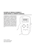
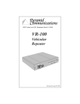
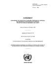
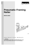
IQ SYSTEM DISPLAY MODULE (IQDM-P)
OWNER’S MANUAL
The IQDM is a handheld programming and diagnostic tool for use with Club Car IQ System vehicles. This owner’s manual includes all information
required to operate the IQDM with Club Car IQ System vehicles only, but does not contain detailed
information for troubleshooting the vehicle. Refer to
the vehicle maintenance and service manual and
supplement for detailed vehicle troubleshooting and
service procedures. For vehicle operation information refer to the vehicle owner’s manual supplied
with the vehicle. If you do not have a vehicle owner’s
manual or a vehicle maintenance and service manual and supplement, they may be obtained from
your Club Car dealer or distributor.
PROGRAM
SCROLL
DISPLAY
MORE INFO
Manual No. 102249202
For use with Kit No. 102248802
Edition Code 0501B0601A
TEST
DIAGNOSTICS
CHANGE
VALUE
NOTICE
This manual contains proprietary information that is protected by copyright. All rights are reserved. No part of
this manual may be photocopied, reproduced, or translated to another language without the written consent
of Club Car, Inc.
Club Car is not liable for errors in this manual or for incidental or consequential damages that result from the
use of the material in this manual.
The information contained in this document is subject to change without notice.
Club Car reserves the right to make design changes to service tools and vehicles without obligation to make
these changes on units previously sold.
This manual effective June 11, 2001.
©2001 Club Car, Inc.
TABLE OF CONTENTS
Safety Details . . . . . . . . . . . . . . . . . . . . . . . . . . . . . . . . . . . . . . . . . . . . . . . . . . . . . . . . . . . . . . . . . . . . . . .
3
Parts Included in Kit . . . . . . . . . . . . . . . . . . . . . . . . . . . . . . . . . . . . . . . . . . . . . . . . . . . . . . . . . . . . . . . . . .
4
General Information . . . . . . . . . . . . . . . . . . . . . . . . . . . . . . . . . . . . . . . . . . . . . . . . . . . . . . . . . . . . . . . . . .
6
Overview . . . . . . . . . . . . . . . . . . . . . . . . . . . . . . . . . . . . . . . . . . . . . . . . . . . . . . . . . . . . . . . . . . . . . . . . . .
6
Program Menu . . . . . . . . . . . . . . . . . . . . . . . . . . . . . . . . . . . . . . . . . . . . . . . . . . . . . . . . . . . . . . . . . . . . . .
8
Test Menu . . . . . . . . . . . . . . . . . . . . . . . . . . . . . . . . . . . . . . . . . . . . . . . . . . . . . . . . . . . . . . . . . . . . . . . . . 10
Diagnostics Menu . . . . . . . . . . . . . . . . . . . . . . . . . . . . . . . . . . . . . . . . . . . . . . . . . . . . . . . . . . . . . . . . . . . 13
Special Diagnostics Menu . . . . . . . . . . . . . . . . . . . . . . . . . . . . . . . . . . . . . . . . . . . . . . . . . . . . . . . . . . . . . 18
Special Program Menu . . . . . . . . . . . . . . . . . . . . . . . . . . . . . . . . . . . . . . . . . . . . . . . . . . . . . . . . . . . . . . . 19
IQDM Troubleshooting . . . . . . . . . . . . . . . . . . . . . . . . . . . . . . . . . . . . . . . . . . . . . . . . . . . . . . . . . . . . . . . . 25
Test Procedures . . . . . . . . . . . . . . . . . . . . . . . . . . . . . . . . . . . . . . . . . . . . . . . . . . . . . . . . . . . . . . . . . . . . . 26
Page 2
IQDM-P Service Tool Owner’s Manual
Safety Details
SAFETY DETAILS
∆ DANGER
• Battery – Explosive gases! Do not smoke. Keep sparks and flames away from the vehicle and
service area. Ventilate when charging or using in an enclosed space. Wear a full face shield
and rubber gloves when working on or near batteries.
• Use extreme caution when using tools, wires, or metal objects near batteries! A short circuit
and (or) spark could cause an explosion.
• Battery – Poison! Contains acid! Causes severe burns. Avoid contact with skin, eyes, or
clothing. Antidotes:
- External: Flush with water. Call a physician immediately.
- Internal: Drink large quantities of milk or water. Follow with milk of magnesia or vegetable
oil. Call a physician immediately.
- Eyes: Flush with water for 15 minutes. Call a physician immediately.
∆ WARNING
• The vehicle operator should not monitor the IQDM while the vehicle is in motion. A technician
can monitor the IQDM while traveling as a passenger in the vehicle. Failure to heed this
warning could result in severe personal injury or death.
• This owner’s manual should be read completely before attempting to operate the IQDM.
Failure to follow the instructions in this manual could result in property damage, severe
personal injury, or death.
• Only trained technicians should repair or service the vehicle. Anyone doing even simple
repairs or service should have knowledge and experience in electrical and mechanical repair.
• Follow the procedures exactly as stated in this manual, and heed all DANGER, WARNING, and
CAUTION statements in this manual, as well as those affixed to the vehicle.
• Improper use of the vehicle or failure to properly maintain it could result in decreased vehicle
performance or severe personal injury.
• Any modification or change to the vehicle that affects the stability or handling of the vehicle,
or increases maximum vehicle speed beyond factory specifications, could result in severe
personal injury or death.
• Check the vehicle owner’s manual for proper location of all vehicle warning decals and make
sure they are in place and are easy to read.
• Wear safety glasses or approved eye protection when servicing the vehicle. Wear a full face
shield and rubber gloves when working on or near batteries.
• Turn key switch OFF and remove key, place Forward/Reverse switch in the NEUTRAL position,
and chock the wheels prior to servicing the vehicle.
• Do not wear loose clothing or jewelry such as rings, watches, chains, etc., when servicing
vehicle.
• Moving parts! Do not attempt to service the vehicle while it is running.
• Use insulated tools when working near batteries or electrical connections. Use extreme
caution to avoid shorting of components or wiring.
• To avoid unintentionally starting the vehicle, place the Tow/Run switch in the TOW position,
then disconnect the batteries, negative cable (–) first, as shown in (Figure 1).
• After disconnecting the batteries, wait 90 seconds for the controller capacitors to discharge.
• If wires are removed or replaced make sure wiring and wire harness are properly routed and
secured. Failure to properly route and secure wiring could result in vehicle malfunction,
property damage or personal injury.
IQDM-P Service Tool Owner’s Manual
Page 3
Parts Included in Kit
∆ CAUTION
• Do not expose the IQDM to direct, bright sunlight for long periods of time. Failure to heed this
caution could result in damage or failure of the IQDM.
Place Tow/Run
Switch in TOW.
FRONT
OF VEHICLE
RUN
T OW
RN
WA
2
ING
5
1
3
4
6
Remove negative
cable first.
PLACE TOW/RUN SWITCH
IN THE TOW POSITION BEFORE
DISCONNECTING OR
CONNECTING BATTERY CABLES
Figure 1 IQ System Battery Configuration
PARTS INCLUDED IN KIT
The IQDM kit should include the items shown (Figure 2).
PROGRAM
TEST
SCROLL
DISPLAY
DIAGNOSTICS
CHANGE
VALUE
MORE INFO
IQ SYSTEM DISPLAY MODULE
IQDM CABLE
102241501
Figure 2 IQDM Parts
Page 4
IQDM-P Service Tool Owner’s Manual
CABLE ADAPTER
102251501
Feature Identification
IQDM-P FEATURE IDENTIFICATION
MENU SELECTION BUTTONS
(Selects the Program menu,
Test menu, Diagnostics Menu,
and, when used in conjunction
with the MORE INFO button,
selects the Special Program menu,
and Special Diagnostics menu)
DISPLAY SCREEN
PROGRAM
SCROLL DISPLAY BUTTONS
(scrolls through menu items
and is used to select items by
scrolling until the desired item is
displayed on the top line of the
display screen)
TEST
SCROLL
DISPLAY
DIAGNOSTICS
CHANGE VALUE BUTTONS
(changes the value of the
selected item in the Program
and Special Program menus)
CHANGE
VALUE
MORE INFO
MORE INFO BUTTON
(Displays more information about
the selected item, or, when used
in conjunction with the menu
selection buttons, selects the
Special Program menu, and
Special Diagnostics menu)
LED (LIGHT-EMITTING DIODE)
(above menu buttons:
indicates selected menu;
above and below CHANGE VALUE
buttons: indicates valid parameter
changes)
TYPICAL
6 PLACES
IQDM-P Service Tool Owner’s Manual
Page 5
General Information
GENERAL INFORMATION
The IQDM handset, when connected to a vehicle, is powered entirely by the vehicle batteries through the
speed controller.
OVERVIEW
PLUGGING THE IQDM INTO THE VEHICLE
1. Connect one end of the cable to the jack located on the bottom of the IQDM unit.
2. Connect the adaptor to the IQDM cable.
3. Remove the sealed cap from the IQDM jack located on the vehicle below the Forward/Reverse switch.
4. Align the keyed portion of the plug with the IQDM jack and connect the plug to the jack (Figure 3).
Figure 3 IQDM to Vehicle Connection
INTRODUCTORY DISPLAY
Immediately after the IQDM is connected to the vehicle, the screen displays a copyright notice and the IQDM
model number. After a few seconds, the screen displays the following information:
• Speed controller model number
• Date the speed controller was manufactured
• Speed controller serial number
• Speed controller software version
In the event that the IQDM does not display any information, or the screen is difficult to read, refer to the IQDM
troubleshooting procedures. See IQDM Troubleshooting on page 25.
Page 6
IQDM-P Service Tool Owner’s Manual
Overview
PROGRAM
TEST
SCROLL
DISPLAY
DIAGNOSTICS
PROGRAM
CHANGE
VALUE
TEST
SCROLL
DISPLAY
DIAGNOSTICS
CHANGE
VALUE
MORE INFO
MORE INFO
Figure 4 Controller Information
Figure 5 Menu Selection Screen
MENU SELECTION
After the controller information has been displayed, the screen will automatically toggle in three-second intervals between the controller information and a prompt to select a menu (Figure 5). Once a menu has been
selected, a light-emitting diode (LED) above the selected menu button will illuminate, indicating the current
menu displayed.
The following menus are accessible on the IQDM:
Program Menu
The Program menu allows the user to view and change custom speed controller settings. See Program Menu
on page 8.
Test Menu
The Test menu displays the status of all controller input devices such as the key switch, Forward/Reverse
switch, etc. See Test Menu on page 10.
Diagnostics Menu
The Diagnostics menu displays all current faults. See Diagnostics Menu on page 13.
Special Diagnostics Menu (Diagnostic History)
The Special Diagnostics menu can be accessed by pressing and holding the MORE INFO button while pressing the DIAGNOSTICS button.
The Special Diagnostics menu displays all faults recorded by the speed controller since the history was last
cleared. Each fault is listed only once, even if the fault has occurred multiple times. See Causes of Faults on
page 13. See also Special Diagnostics Menu on page 18.
IQDM-P Service Tool Owner’s Manual
Page 7
Program Menu
Special Program Menu
The Special Program menu can be accessed by pressing and holding the MORE INFO button while pressing
the PROGRAM button.
The Special Program menu allows the user to access many specialized features such as cloning speed controller settings, clearing diagnostic fault history, adjusting the IQDM display contrast, etc. See Special Program Menu on page 19.
PROGRAM
TEST
SCROLL
DISPLAY
DIAGNOSTICS
PROGRAM
SCROLL
DISPLAY
CHANGE
VALUE
MORE INFO
Figure 6 Program Menu Introduction Screen
TEST
DIAGNOSTICS
CHANGE
VALUE
MORE INFO
Figure 7 Speed Setting Menu Selection
PROGRAM MENU
The Program menu is activated by pressing the PROGRAM button (Figure 6). When the Program menu is
active, use the SCROLL DISPLAY buttons to select items in the menu. The item on the top line of the display
screen is the selected item. When an item is selected, the MORE INFO button can be pressed to get more
information about the parameter such as the allowable range of settings. Press the MORE INFO button again
to return to the menu.
LED’s on the CHANGE VALUE buttons will illuminate to indicate valid value changes that can be made to the
selected item. See following NOTE.
NOTE: For a menu item with valid settings of 1, 2, 3, and 4: If the parameter is set to 1, the change value
up LED would be illuminated, indicating that the value can be increased. The value down LED
would NOT be illuminated, indicating that a value lower than 1 cannot be selected. If the parameter
is set for 2, both of the change value LED’s would be illuminated, indicating that the value can be
increased or decreased.
Page 8
IQDM-P Service Tool Owner’s Manual
Program Menu
The following parameters can be programmed with the IQDM from the Program menu:
SPEED SETTING
The vehicle’s top speed can be changed by selecting values 1 through 3 (Figure 7). If a value of 4 is displayed
for the speed setting, a special access code has been entered to place the vehicle in "private speed mode".
A speed setting of 4 cannot be selected with the speed setting menu item. For additional information on speed
setting 4, refer to Code A, Code B, and Code C. See Code A, Code B, and Code C on page 10.
SPEED SETTING
DESCRIPTION
VEHICLE SPEED
1
Commercial speed
8.0 mph
(12.9 km/h)
2
Slow golf speed
13.4 mph
(21.6 km/h)
3
Normal golf speed
14.8 mph
(23.8 km/h)
4
Private speed mode
19.6 mph
(31.5 km/h)
FAST ACCEL
Fast acceleration is an option that can be enabled or disabled. With fast acceleration turned on, the vehicle will
accelerate at a noticeably faster rate. With this feature turned off, the vehicle speed will gradually increase,
even if the accelerator is quickly pressed to the floor.
PEDAL UP MODE
Three options exist for pedal up (motor braking) mode. When the accelerator pedal is released, motor braking
will slow the vehicle to a speed of approximately 11 mph (17.7 km/h) when pedal up motor braking is enabled.
If pedal up motor braking is disabled (option 0), the vehicle will coast to a stop when the pedal is released. See
following NOTE.
NOTE: Pedal up mode does not affect top vehicle speed. If the accelerator pedal is released when the
vehicle is going down an incline, the motor braking function will activate, slowing the vehicle to the
speed setting defined in the Program menu. See Speed Setting on page 9.
PEDAL UP MODE SETTING
MODE
OPERATION DESCRIPTION
0
Off
Pedal up motor braking is disabled
1
Mild pedal up
Mild Pedal up motor braking
2
Aggressive pedal up
Aggressive Pedal up motor braking
SPEED CAL
The speed cal (speed calibration) menu item allows the user to fine tune the vehicle speed. This feature cannot be used to increase the vehicle speed. The acceptable range for speed calibration is 0 to 10. Each time
the number is increased, the top speed will be decreased by 0.12 mph (0.2 km/h). The top vehicle speed will
be determined by the speed setting menu item and the speed calibration setting. For example, if the speed
setting is set for a value of 3 (14.8 mph (23.8 km/h)), and the speed calibration is set for 5, the total top speed
of the vehicle should be approximately 14.2 mph (22.9 km/h).
IQDM-P Service Tool Owner’s Manual
Page 9
Test Menu
CODE A, CODE B, AND CODE C
The code entries are used to place the vehicle in "private speed mode", speed setting code 4. Each vehicle
has a unique code for placing the vehicle in this mode. A vehicle programmed for "private speed mode", speed
setting 4, does not conform to ANSI Z130.1 – American National Standard for Golf Cars – Safety and Performance Specifications because it is capable of speeds in excess of 15 mph (24.1 km/h). For more information
on this feature, contact your local Club Car distributor or dealer.
PROGRAM
PROGRAM
TEST
SCROLL
DISPLAY
TEST
DIAGNOSTICS
DIAGNOSTICS
SCROLL
DISPLAY
CHANGE
VALUE
CHANGE
VALUE
MORE INFO
MORE INFO
Figure 8 Test Menu Introduction Screen
Figure 9 Test Menu
TEST MENU
The Test menu is activated by pressing the TEST button on the IQDM (Figure 8). When the Program menu is
active, the SCROLL DISPLAY buttons can be used to view items in the menu (Figure 9). See following
NOTE. All information in the Test menu is updated in real time, allowing the trained technician to troubleshoot
the vehicle by monitoring the IQDM as the key switch is cycled, Forward/Reverse switch is activated, etc.
NOTE: The item on the top line of the display screen is the selected item. If so desired, the MORE INFO
button can be pressed to display only the selected item.
Since the Test menu is updated while the vehicle is in operation, the trained technician has the ability to monitor the status of several components in conditions or locations where a problem with vehicle performance has
been reported. See following Warning.
∆ WARNING
• The vehicle operator should not monitor the IQDM while the vehicle is in motion. A technician
can monitor the IQDM while traveling as a passenger in the vehicle. Failure to heed this
warning could result in severe personal injury or death.
Page 10
IQDM-P Service Tool Owner’s Manual
Test Menu
The following parameters can be monitored in real time with the IQDM from the Test menu:
PASSWORD TRIES
A password is required to place the vehicle in "private speed mode" (speed setting 4). The speed controller
will log unsuccessful and unauthorized attempts to place the speed controller in "private speed mode". If
repeated attempts are unsuccessful, the speed controller will permanently lock out access to "private speed
mode". In the event that "private speed mode" is locked out, the controller must be removed and shipped to
Club Car before it can ever be placed in "private speed mode". See Code A, Code B, and Code C on
page 10.
THROTTLE %
Indicates the position of the accelerator pedal from 0% (pedal undepressed) to 100% (pedal fully depressed).
This item can be monitored when the key switch is in the ON or OFF position.
BATT VOLTAGE
Displays the current battery voltage.
HEATSINK °C
Displays the temperature (in degrees Celsius) of the speed controller heatsink. During normal operating conditions, the heatsink temperature should be below 85 °C ±5 °C (185 °F ±41 °F). See following NOTE.
NOTE: Improper brake adjustment can sometimes cause the operating current to be higher than normal.
This higher current increases the temperature of the speed controller heatsink.
ARM CURRENT
Displays the motor armature current (in amperes).
FIELD CURRENT
Displays the motor field current (in amperes).
ARM PWM
Displays motor armature PWM (pulse width modulation). The range of pulse width modulation is 0% to 100%.
When the vehicle is operating at full speed, the pulse width modulation should be at 100%.
FIELD PWM
Displays motor field PWM (pulse width modulation). The range of pulse width modulation is 0% to 100%.
When the vehicle is operating at full speed, the pulse width modulation should fluctuate.
SPEED PULSES
The speed pulses menu item displays the activity of the motor speed sensor. With the key switch in the OFF
position, the Forward/Reverse switch in the NEUTRAL position, and the vehicle at rest, the IQDM should
should indicate that speed pulses are off. When the vehicle is gently pushed a short distance, the IQDM
should indicate that speed pulses are on.
IQDM-P Service Tool Owner’s Manual
Page 11
Test Menu
FOOT INPUT
Indicates the status of the MCOR (motor controller output regulator) internal limit switch: on or off. When the
accelerator pedal is undepressed, the IQDM should indicate that the limit switch is off. When the accelerator
pedal is pressed and the key swtich is in the ON position, the display should indicate that the limit switch is on.
FORWARD INPUT
With the Forward/Reverse switch in the NEUTRAL or REVERSE position, the IQDM should indicate that the
forward input is off. When the Forward/Reverse switch is placed in the FORWARD position, the IQDM should
indicate that the forward input is on.
REVERSE INPUT
With the Forward/Reverse switch in the NEUTRAL or FORWARD position, the IQDM should indicate that the
reverse input is off. When the Forward/Reverse switch is placed in the REVERSE position, the IQDM should
indicate that the reverse input is on.
MAIN CONT
Displays the current solenoid (main contactor) state. When the contactor is activated, the IQDM indicates that
the solenoid is on. When the contactor is not activated, the IQDM indicates that the solenoid is off.
KEY INPUT
Displays the position of the key switch: OFF or ON.
PROGRAM
TEST
SCROLL
DISPLAY
DIAGNOSTICS
CHANGE
VALUE
MORE INFO
Figure 10 Diagnostics Menu Introduction Screen
Page 12
IQDM-P Service Tool Owner’s Manual
Diagnostics Menu
DIAGNOSTICS MENU
The Diagnostics menu is activated by pressing the DIAGNOSTICS button on the IQDM (Figure 10). When the
Diagnostics menu is active and there are more than 4 active faults, the SCROLL DISPLAY buttons can be
used to scroll through the faults in the menu. See following NOTE. Any fault displayed in the Diagnostics
menu will aid the trained technician in troubleshooting the vehicle. Faults displayed in the Diagnostics menu
often indicate which components in the electrical system need to be tested and/or replaced.
NOTE: The MORE INFO button can be pressed to display more information about the selected fault. The
item on the top line of the display screen is the selected item.
Note that the faults displayed in the Diagnostics menu may not include all of the faults listed in the Special
Diagnostics menu. This is because the faults displayed in the Diagnostics menu are faults that are currently
active. Once a fault has been detected by the speed controller, the code remains in the Diagnostics menu until
the problem has been corrected. In addition, the fault is stored in the speed controller’s memory for display in
the Special Diagnostics menu. See Special Diagnostics Menu on page 18.
Since the Diagnostics menu is updated while the vehicle is in operation, the trained technician has the ability
to monitor the occurrence of faults in conditions or locations where a problem with vehicle performance has
been reported. See following Warning.
∆ WARNING
• The vehicle operator should not monitor the IQDM while the vehicle is in motion. A technician
can monitor the IQDM while traveling as a passenger in the vehicle. Failure to heed this
warning could result in severe personal injury or death.
CAUSES OF FAULTS
Some common causes of faults are:
• Loose, broken, or disconnected wires or connectors
• Failed components
• Improper adjustment or installation of electrical or mechanical components (examples: brake adjustment, improper MCOR installation)
• Improper wiring of electrical components
As shown above, there are many possible causes for faults to occur, and the speed controller has a programmed reaction to each fault that is based on the fault currently detected. The technician should be familiar
with the detected faults and the controller’s reactions to faults to ensure a proper diagnosis.
An example of a possible mis-diagnosis of a vehicle due to a fault: If the three-pin speed sensor wire has been
disconnected, the speed controller will detect a speed sensor fault. When a speed sensor fault is detected, the
controller responds to the fault by limiting the vehicle speed to 1/2 of its normal top speed. If the technician
reaches the conclusion that the vehicle is running slowly because batteries are heavily discharged, he has
made an improper diagnosis of the problem.
The vehicle speed controller should be checked for fault codes before any service is performed.
The speed controller, after detecting a fault, will respond in one or more of the following ways:
• A. Reduce vehicle speed to zero by reducing armature current
• B. Reduce vehicle speed to zero by reducing field current to zero
• C. Turn off the solenoid
• D. Cause the vehicle to run at half speed
IQDM-P Service Tool Owner’s Manual
Page 13
Diagnostics Menu
• E. Gradually reduce the armature current limit
• F. Quickly reduce the armature current until speed sensor pulses occur
• G. Reduce field current and beep reverse buzzer at a fast rate
CONTROLLER
FAULT
CONTROLLER
RESPONSE
HW FAILSAFE
A, B, C
THROTTLE FAULT 1
A
SPEED SENSOR
D
MAIN WELDED
D
MAIN DRIVER ON
D
MAIN DRIVER OFF
A, C
MAIN CONT DNC
B
MAIN COIL FAULT
A
FIELD MISSING
A, B, C
HPD
A
PROC/WIRING
A
OVERVOLTAGE
A, B, G
LOW BATTERY
E
THERMAL CUTBACK
E
MOTOR STALL
F
MAIN DROPOUT
OPEN ARMATURE
A, C
A
MAX PASSWORD TRIES
(no action taken)
INCORRECT PASSWORD
(no action taken)
FAULT RECOVERY
When a fault is detected by the speed controller, the speed controller will attempt to recover from the fault and
resume normal operation. In the case of an intermittent problem such as a loose wiring connection, the controller may be able to recover and operate normally for a while, but the problem should be repaired before
placing the vehicle in service.
Depending on the type of fault, the controller will attempt to recover immediately after the condition clears or
after the accelerator pedal has been cycled (released and pressed again).
CONTROLLER
FAULT
CONTROLLER ATTEMPTS
TO RECOVER
HW FAILSAFE
When key switch is cycled
THROTTLE FAULT 1
When condition clears
SPEED SENSOR
When condition clears
MAIN WELDED
When condition clears
MAIN DRIVER ON
When condition clears
Page 14
IQDM-P Service Tool Owner’s Manual
Diagnostics Menu
CONTROLLER
FAULT
CONTROLLER ATTEMPTS
TO RECOVER
MAIN DRIVER OFF
When accel. pedal is cycled
MAIN CONT DNC
When accel. pedal is cycled
MAIN COIL FAULT
When accel. pedal is cycled
FIELD MISSING
When accel. pedal is cycled
HPD
When accel. pedal is cycled
PROC/WIRING
When condition clears
OVERVOLTAGE
When condition clears
LOW BATTERY VOLTAGE
When condition clears
THERMAL CUTBACK
When condition clears
MOTOR STALL
When condition clears
MAIN DROPOUT
When accel. pedal is cycled
OPEN ARMATURE
When condition clears and
accel. pedal is cycled
MAX PASSWORD TRIES
When Tow/Run switch is
cycled
INCORRECT PASSWORD
When Tow/Run switch is
cycled
The following faults can be detected by the IQ System controller:
HW FAILSAFE
The armature drive FET’s (field effect transistors) regulate the armature current. If the speed controller
detects a failure of the armature drive FET’s or circuitry, a hardware failsafe fault is detected.
THROTTLE FAULT 1
If the MCOR (Motor Controller Output Regulator) voltage is less than 0.20 volts or greater than 4.80 volts, the
controller detects a throttle fault.
SPEED SENSOR
If the speed controller does not detect pulses from the speed sensor while the controller outputs power
(greater than 75% armature PWM) to the motor, a speed sensor fault is detected.
MAIN WELDED
If the speed controller detects that the solenoid contacts are welded closed, a main welded fault is detected.
MAIN DRIVER ON
If the FET that controls the closing of the solenoid contacts is found to be energized when it should not be, a
main driver on fault is detected by the speed controller.
IQDM-P Service Tool Owner’s Manual
Page 15
Diagnostics Menu
MAIN DRIVER OFF
If the FET that controls the closing of the solenoid is not energized when it should be, a main driver off fault
is detected by the speed controller.
MAIN CONT DNC
The main cont dnc (main contactor (solenoid) did not close) fault is detected when the speed controller has
sent voltage to the solenoid activating coil but the solenoid contacts are not closed.
MAIN COIL FAULT
If the speed controller determines that the solenoid is not closing as a result of a solenoid coil failure, a main
coil fault is detected.
FIELD MISSING
If the speed controller is operating at a duty cycle of greater than 90% (almost full speed) and the field current
is less than 3 amps, a field missing fault is detected by the speed controller.
HPD
The HPD (High Pedal Detect) fault is detected if the accelerator pedal is already depressed when the key
switch is turned to the ON position. This fault is also detected if the accelerator pedal is pressed when the
selected direction is changed by pressing the Forward/Reverse switch. This fault, when not caused by the
operator, can indicate that the pedal limit switch has failed closed.
PROC/WIRING
This fault is detected if the Forward/Reverse switch is giving a signal to place the controller in forward and
reverse at the same time. This rare fault can be caused by a failed switch or improper vehicle wiring.
OVERVOLTAGE
If the speed controller detects that the battery voltage is too high (68.4 to 75.6 volts DC), the overvoltage fault
is detected.
LOW BATTERY VOLTAGE
If the battery voltage falls below 34 volts ±5%, the low battery voltage fault is detected by the speed controller.
THERMAL CUTBACK
If the controller heatsink temperature is found to be in excess of 85 °C ±5 °C (185 °F ±41 °F) or below –25 °C
±5 °C (–13 °F ±34.3 °F), the thermal cutback fault is detected.
MOTOR STALL
If the motor current is high and there is no movement of the vehicle wheels for a short period of time, a motor
stall is detected by the speed controller. This fault can be caused by an operator holding the vehicle on a hill
by depressing the accelerator pedal instead of the brake pedal.
Page 16
IQDM-P Service Tool Owner’s Manual
Diagnostics Menu
MAIN DROPOUT
If the controller detects that the solenoid contacts have opened while the vehicle is in operation, a main dropout fault is detected.
OPEN ARMATURE
If the accelerator pedal is pressed 2/3 to the floor, the armature current is less than 20 amps, and there are no
speed sensor pulses, an open armature fault is detected.
INCORRECT PASSWORD
Each vehicle has a password in the form of a unique set of codes used to place the vehicle in "private speed
mode". If a set of codes has been entered incorrectly, the incorrect password fault is declared. For additional
information on codes, refer to Code A, Code B, and Code C. See Code A, Code B, and Code C on page 10.
See also Password Tries on page 11.
MAX PASSWORD TRIES
The max password tries fault is declared when the incorrect password fault has been declared several times.
In the event that the max password tries fault is indicated, the speed controller must be removed and shipped
to Club Car before it can ever be placed in "private speed mode". See Code A, Code B, and Code C on
page 10. See also Password Tries on page 11.
PROGRAM
TEST
SCROLL
DISPLAY
DIAGNOSTICS
CHANGE
VALUE
MORE INFO
Figure 11 Special Diagnostics Menu
IQDM-P Service Tool Owner’s Manual
Page 17
Special Diagnostics Menu
SPECIAL DIAGNOSTICS MENU
The Special Diagnostics menu is accessed by holding the MORE INFO button while pressing the diagnostics
button. The Special Diagnostics menu displays all of the faults detected by the speed controller since the last
time the fault history has been cleared (Figure 11). The faults displayed in this menu may or may not be currently active. Once a fault has been detected, it is stored in the memory of the speed controller for display on
the Special Diagnostics menu. Each detected fault is listed only once, even if the fault has occurred multiple
times.
FAULT HISTORY
The fault history can be useful in determining the cause of a vehicle problem; however, the fault history alone
should not be the factor that determines when a component is replaced. Some faults detected by the speed
controller are not the result of a failed component, and are instead the result of operator error. If a fault
appears in the fault history, the trained technician should attempt to determine when and where the fault has
occurred. For example, if the motor stall fault is present in the fault history, the trained technician may be able
to determine the location on the course where an operator has held the vehicle on a hill by using the accelerator pedal.
CLEARING FAULT HISTORY
After a repair has been made, the fault history should be cleared. This will enable the trained technician to
properly troubleshoot the vehicle in the future, in the event that another problem occurs. It is recommended
that the fault history be cleared in order to avoid the replacement of a component that caused a fault in the
past, but has been replaced and is now functioning correctly. For example, if the MCOR device was disconnected and the speed controller detected a fault code associated with the throttle, the fault history should be
cleared so that any future problem is not diagnosed incorrectly as a throttle problem. See Clear Diag History
on page 23.
PROGRAM
TEST
SCROLL
DISPLAY
DIAGNOSTICS
Figure 12 Special Program Menu
IQDM-P Service Tool Owner’s Manual
TEST
SCROLL
DISPLAY
CHANGE
VALUE
MORE INFO
Page 18
PROGRAM
DIAGNOSTICS
CHANGE
VALUE
MORE INFO
Figure 13 Special Program Menu Items
Special Program Menu
SPECIAL PROGRAM MENU
The Special Program menu is accessed by holding the MORE INFO button while pressing the program button. The Special Program menu enables the trained technician to perform many useful functions (Figure 12).
The special program functions are selected in the same way that items are selected on other menus. When
the menu has been activated (Figure 13), use the SCROLL DISPLAY buttons to select a function. The
selected function always appears on the top line of the display. Once a function has been selected, press the
MORE INFO button. If a function has been accidently selected, press the more info button to return to the
Special Program menu without making any changes. The display screen will indicate that no change was
made (Figure 14).
PROGRAM
TEST
SCROLL
DISPLAY
DIAGNOSTICS
CHANGE
VALUE
MORE INFO
Figure 14 Operation Cancelled
RESET ALL SETTINGS
In the event that a mistake was made and one or more changes should not have been made with the IQDM,
the speed controller settings can be reverted to the original settings from the beginning of the session (when
the IQDM was plugged into the vehicle). This function is similar to the "undo" command on a PC and will work
correctly only when the IQDM has not been unplugged and power to the speed controller has not been interrupted.
Resetting All Settings
1. During an active session when the settings need to be returned to the original values (the values that
were active at the beginning of the session), press and hold the MORE INFO button while pressing the
PROGRAM button.
IQDM-P Service Tool Owner’s Manual
Page 19
Special Program Menu
2. Press the SCROLL DISPLAY down button until the "reset all settings" function is on the top line of the
display screen.
3. After pressing the MORE INFO button, a prompt will appear to confirm the operation (Figure 15). To
abort the operation, press the CHANGE VALUE down button; otherwise, proceed to the next step.
4. Press the CHANGE VALUE up button to confirm the operation.
5. The IQDM will display a "working..." message for the next few seconds while the controller settings are
being reset (Figure 16).
6. When the IQDM is finished resetting the speed controller settings, a confirmation message is displayed.
CONT SETTINGS→ PROG
This function transfers all of the speed controller settings (except for "private speed mode") from the vehicle
speed controller to the IQDM. This enables the trained technician to "clone" a speed controller. Once the
speed controller settings have been transferred to the IQDM, the technician can then connect the IQDM to
another vehicle and transfer the stored settings into the speed controller.
Speed Controller Cloning – Transferring Settings from the Vehicle to the IQDM
1. Locate a vehicle that has the desired speed controller settings.
2. Turn the key switch to the OFF position, place the Forward/Reverse handle in the NEUTRAL position,
and lock the park brake.
3. Plug the IQDM into the vehicle.
3.1. Connect one end of the cable to the jack located on the bottom of the IQDM unit.
3.2. Connect the adaptor to the IQDM cable.
3.3. Remove the sealed cap from the IQDM jack located on the vehicle below the Forward/Reverse
switch.
3.4. Align the keyed portion of the plug with the IQDM jack and connect the plug to the jack (Figure 3).
4. Press and hold the MORE INFO button while pressing the PROGRAM button.
5. Press the SCROLL DISPLAY down button until the "Cont Settings→ Prog" function is on the top line of
the display screen.
6. After pressing the MORE INFO button, a prompt will appear to confirm the operation (Figure 15). To
abort the operation, press the CHANGE VALUE down button; otherwise, proceed to the next step.
7. Press the CHANGE VALUE up button to confirm the operation.
8. The IQDM will display a "working..." message for the next few seconds while the controller settings are
being stored in the IQDM’s memory (Figure 16).
9. When the IQDM is finished recording the speed controller settings, a confirmation message is displayed
(Figure 17).
Page 20
IQDM-P Service Tool Owner’s Manual
Special Program Menu
10. With the controller settings stored in the memory of the IQDM, the IQDM can be used to transfer all of
the desired speed controller settings to any IQ System vehicle or group of IQ System vehicles. See
Speed Controller Cloning – Transferring Settings from the IQDM to the Vehicle on page 22.
PROGRAM
PROGRAM
TEST
SCROLL
DISPLAY
DIAGNOSTICS
CHANGE
VALUE
MORE INFO
Figure 15 Controller Settings Transfer to IQDM
TEST
SCROLL
DISPLAY
SCROLL
DISPLAY
CHANGE
VALUE
MORE INFO
PROGRAM
TEST
DIAGNOSTICS
DIAGNOSTICS
Figure 16 IQDM Working
PROGRAM
SCROLL
DISPLAY
CHANGE
VALUE
MORE INFO
Figure 17 Controller Settings Saved in IQDM
TEST
DIAGNOSTICS
CHANGE
VALUE
MORE INFO
Figure 18 Controller Settings Transfer from IQDM
IQDM-P Service Tool Owner’s Manual
Page 21
Special Program Menu
PROG SETTINGS→ CONT
This function transfers all of the speed controller settings (except for "private speed mode") from the IQDM to
the vehicle speed controller. This enables the trained technician to "clone" a speed controller. Once the speed
controller settings have been transferred to the IQDM, the technician can then connect the IQDM to another
vehicle and transfer the stored settings into the speed controller.
Speed Controller Cloning – Transferring Settings from the IQDM to the Vehicle
1. Perform this procedure with an IQDM that has the desired speed controller settings. See Speed Controller Cloning – Transferring Settings from the Vehicle to the IQDM on page 20.
2. Locate a vehicle that does not have the desired speed controller settings.
3. Turn the key switch to the OFF position, place the Forward/Reverse handle in the NEUTRAL position,
and lock the park brake.
4. Plug the IQDM into the vehicle.
4.1. Connect one end of the cable to the jack located on the bottom of the IQDM unit.
4.2. Connect the adaptor to the IQDM cable.
4.3. Remove the sealed cap from the IQDM jack located on the vehicle below the Forward/Reverse
switch.
4.4. Align the keyed portion of the plug with the IQDM jack and connect the plug to the jack (Figure 3).
5. Press and hold the MORE INFO button while pressing the PROGRAM button.
6. Press the SCROLL DISPLAY down button until the "Prog Settings→ Cont" function is on the top line of
the display screen.
7. After pressing the MORE INFO button, a prompt will appear to confirm the operation (Figure 18). To
abort the operation, press the CHANGE VALUE down button; otherwise, proceed to the next step.
8. Press the CHANGE VALUE up button to confirm the operation.
PROGRAM
TEST
SCROLL
DISPLAY
DIAGNOSTICS
CHANGE
VALUE
MORE INFO
Figure 19 IQDM Settings Transferred to Controller
Page 22
PROGRAM
IQDM-P Service Tool Owner’s Manual
TEST
SCROLL
DISPLAY
DIAGNOSTICS
CHANGE
VALUE
MORE INFO
Figure 20 Clearing Diagnostic History
Special Program Menu
9. The IQDM will display a "working..." message for the next few seconds while the controller settings are
transferred the IQDM’s memory to the speed controller (Figure 16).
10. When the IQDM is finished transferring the speed controller settings, a confirmation message is displayed (Figure 19).
11. Repeat this procedure for additional vehicles that need to be programmed with the same IQDM settings.
CLEAR DIAG HISTORY
The clear diagnostic history function will erase the history of faults that are stored in the vehicle speed controller and displayed on the Special Diagnostics menu. See Special Diagnostics Menu on page 18.
Clearing the Diagnostic History
1. Turn the key switch to the OFF position, place the Forward/Reverse handle in the NEUTRAL position,
and lock the park brake.
2. Plug the IQDM into the vehicle.
2.1. Connect one end of the cable to the jack located on the bottom of the IQDM unit.
2.2. Connect the adaptor to the IQDM cable.
2.3. Remove the sealed cap from the IQDM jack located on the vehicle below the Forward/Reverse
switch.
2.4. Align the keyed portion of the plug with the IQDM jack and connect the plug to the jack (Figure 3).
3. Press and hold the MORE INFO button while pressing the PROGRAM button.
4. Press the SCROLL DISPLAY down button until the "Clear Diag History" function is on the top line of the
display screen.
5. After pressing the MORE INFO button, a prompt will appear to confirm the operation (Figure 20). To
abort the operation, press the CHANGE VALUE down button; otherwise, proceed to the next step.
6. Press the CHANGE VALUE up button to confirm the operation.
7. The diagnostic history is immediately erased and a confirmation message is displayed (Figure 21).
CONTRAST ADJUSTMENT
It may occasionally be necessary to adjust the contrast of the display screen. After selecting the contrast
adjustment item from the Special Program menu, use the CHANGE VALUE buttons to adjust the contrast for
the best readability (Figure 22).
LANGUAGE SELECTION
English is the only language supported by the IQDM. There are two selectable options, "English", and
"numeric". The numeric option should never be selected, as this will change the Test menu items from English
words to numeric values. These numeric values are useful for the OEM only, and will be of no use to the
trained technician.
IQDM-P Service Tool Owner’s Manual
Page 23
Special Program Menu
CONTRAST TOO DARK
PROGRAM
TEST
SCROLL
DISPLAY
DIAGNOSTICS
CHANGE
VALUE
PROPER CONTRAST ADJUSTMENT
MORE INFO
CONTRAST TOO LIGHT
Figure 21 Diagnostic History Cleared
Figure 22 Contrast Adjustment
PROGRAM
PROGRAM
TEST
TEST
SCROLL
DISPLAY
SCROLL
DISPLAY
DIAGNOSTICS
DIAGNOSTICS
CHANGE
VALUE
CHANGE
VALUE
MORE INFO
MORE INFO
Figure 23 Programmer Information
Figure 24 Speed Controller Information
PROGRAMMER INFO
This menu selection displays information pertaining to the IQDM. The information provided from this menu
selection includes programmer model number, the date the IQDM was manufactured, and the IQDM software
version (Figure 23).
Page 24
IQDM-P Service Tool Owner’s Manual
IQDM Troubleshooting
CONTROLLER INFO
This menu selection displays information pertaining to the speed controller. The information provided from this
menu selection includes the speed controller model number, the date the speed controller was manufactured,
the speed controller serial number, and the speed controller software version (Figure 24).
IQDM TROUBLESHOOTING
In the event that the IQDM does not function as described in this manual, the following troubleshooting guide
should be studied and the referenced test procedures should be performed to troubleshoot the IQDM.
TROUBLESHOOTING GUIDE
SYMPTOM
POSSIBLE CAUSES
CORRECTIVE ACTION
IQDM display screen is blank
IQDM cord and/or adaptor is
disconnected
See Plugging the IQDM into the Vehicle
on page 6.
Vehicle batteries – loose terminals or
corrosion
Section 13 – Batteries in the IQ System
Maintenance and Service Supplement
Vehicle batteries – improperly wired
Section 13 – Batteries in the IQ System
Maintenance and Service Supplement
Vehicle batteries – batteries failed
Section 13 – Batteries in the IQ System
Maintenance and Service Supplement
Vehicle batteries – batteries not fully
charged
Section 13 – Batteries in the IQ System
Maintenance and Service Supplement
IQDM cord has failed
Test Procedure 1 – IQDM Cord on
page 27
IQDM cord adaptor has failed
Test Procedure 2 – IQDM Cord Adaptor
on page 27
IQDM jack (on vehicle F&R switch) has
failed
Test Procedure 3 – IQDM Jacks (Located
on Vehicle F&R Switch and speed
controller) on page 27
Contrast Setting is too light
See Contrast Adjustment on page 23.
Onboard computer is in power-down
mode
Drive the vehicle for a short distance and
reconnect the IQDM to the vehicle.
Onboard computer malfunction
Section 11 – Electrical System and
Testing in the IQ System Maintenance and
Service Supplement
Loose vehicle wire harness connections
Test Procedure 3 – IQDM Jacks (Located
on Vehicle F&R Switch and speed
controller) on page 27
Speed controller malfunction
Section 11 – Electrical System and
Testing in the IQ System Maintenance and
Service Supplement
IQDM has failed
Replace IQDM
IQDM is in "numeric" language mode.
See Language Selection on page 23.
Menu items appear as numbers, rather
than text
Troubleshooting Guide continued on next page...
IQDM-P Service Tool Owner’s Manual
Page 25
Test Procedures
TROUBLESHOOTING GUIDE
SYMPTOM
POSSIBLE CAUSES
CORRECTIVE ACTION
Display screen shows jumbled or
undecipherable characters
Speed controller malfunction
Section 11 – Electrical System and
Testing in the IQ System Maintenance and
Service Supplement
IQDM malfunction
Disconnect the IQDM cord from the
vehicle. Wait a few seconds and reconnect
the IQDM to the vehicle
IQDM Display screen LCD is damaged
Test Procedure 4 – LCD Display Screen
Test on page 29
Loose connection at IQDM jack
Test Procedure 3 – IQDM Jacks (Located
on Vehicle F&R Switch and speed
controller) on page 27
Intermittent IQDM cord failure
Test Procedure 1 – IQDM Cord on
page 27
Intermittent IQDM cord adaptor failure
Test Procedure 2 – IQDM Cord Adaptor
on page 27
Loose vehicle wire harness connections
Test Procedure 3 – IQDM Jacks (Located
on Vehicle F&R Switch and speed
controller) on page 27
IQDM malfunction
Disconnect the IQDM cord from the
vehicle. Wait a few seconds and reconnect
the IQDM to the vehicle
Vehicle batteries – loose terminals or
corrosion
Section 13 – Batteries in the IQ System
Maintenance and Service Supplement
Vehicle batteries – improperly wired
Section 13 – Batteries in the IQ System
Maintenance and Service Supplement
Vehicle batteries – batteries failed
Section 13 – Batteries in the IQ System
Maintenance and Service Supplement
Vehicle batteries – batteries not fully
charged
Section 13 – Batteries in the IQ System
Maintenance and Service Supplement
Speed controller malfunction
Section 11 – Electrical System and
Testing in the IQ System Maintenance and
Service Supplement
IQDM is “locked-up” – buttons do not
respond
TEST PROCEDURES
The following test procedures enable the technician to test the IQDM handset and the components of the IQ
System vehicle that are related to the proper operation of the IQDM. This owner’s manual does not contain
detailed information for troubleshooting the vehicle. Refer to the vehicle maintenance and service manual for
detailed vehicle troubleshooting and service procedures.
∆ WARNING
• If wires are removed or replaced make sure wiring and wire harness are properly routed and
secured. Failure to properly route and secure wiring could result in vehicle malfunction,
property damage or personal injury.
Page 26
IQDM-P Service Tool Owner’s Manual
Test Procedures
INDEX OF TEST PROCEDURES
1. IQDM Cord
2. IQDM Cord Adaptor
3. IQDM Jacks (Located on Vehicle F&R Switch and speed controller)
4. LCD Display Screen Test
TEST PROCEDURE 1 – IQDM CORD
Read DANGER, WARNING, and CAUTION on page 3.
1. Using a multimeter set for 200 Ω (ohms), place the red (+) probe into one of the terminals on the end of
the cord with the square plug.
2. Place the black (–) probe on each of the pins, one at a time, on the other plug of the plug.
3. The multimeter should indicate continuity on only one pin. If any other reading is obtained, the cord must
be replaced.
4. Repeat the procedure three more times, each time with the red (+) probe inserted into a different terminal
on the end of the cord with the square plug.
TEST PROCEDURE 2 – IQDM CORD ADAPTOR
Read DANGER, WARNING, and CAUTION on page 3.
The procedure for testing the IQDM cord adaptor is similar to the cord test.
1. Using a multimeter set for 200 Ω (ohms), place the red (+) probe into one of the terminals on the end of
the adapter with the square plug.
2. Place the black (–) probe on each of the pins, one at a time, on the other plug of the adaptor.
3. The multimeter should indicate continuity on only one pin. If any other reading is obtained, the adaptor
must be replaced.
4. Repeat the procedure three more times, each time with the red (+) probe inserted into a different terminal
on the end of the adaptor with the square plug.
TEST PROCEDURE 3 – IQDM JACKS (LOCATED ON VEHICLE F&R SWITCH AND
SPEED CONTROLLER)
Read DANGER, WARNING, and CAUTION on page 3.
1. Turn the key switch to the OFF position, place the Forward/Reverse handle in the NEUTRAL position,
and lock the park brake.
2. Place the Tow/Run switch in the TOW position, disconnect the batteries, negative (–) cable first, and wait
90 seconds for the speed controller capacitors to discharge. See WARNING on page 3.
IQDM-P Service Tool Owner’s Manual
Page 27
Test Procedures
2
F
1
4
5
Figure 25 Forward/Reverse Rocker Switch With IQDM Jack
3. Check the IQDM jack at the Forward/Reverse switch case.
3.1. Remove the three self-tapping screws that hold the F&R rocker switch case (2) to the body
(Figure 25).
3.2. Disconnect the four-pin connectors (4 and 5) and visually inspect the contacts for damage and corrosion. Inspect the IQDM jack, located on the bottom of the switch case (2). Repair and replace
parts as necessary.
3.3. If no problem is found, connect the multi-pin connectors and install the F&R switch case.
3.4. Install the three self-tapping screws that hold the F&R rocker switch case (2) to the body. Tighten
to 20 in-lb (2.2 N·m).
4. Check the IQDM jack on the speed controller.
4.1. Remove the two screws securing the rear body access panel and remove the access panel.
4.2. Remove the two screws (5) securing the controller cover (1) to the component mounting plate
(Figure 26).
4.3. Disconnect the square four-pin connector (3) from the speed controller.
4.4. Connect the IQDM cord to the IQDM.
4.5. Connect the other end of the IQDM cord (without the adapter) (4) to the four-pin connector of the
speed controller (2) (Figure 26).
4.6. Connect the vehicle batteries, positive (+) cable first.
4.7. If the IQDM functions when connected directly to the speed controller, the adapter plug or vehicle
wire harness should be thoroughly tested. See Test Procedure 2 – IQDM Cord Adaptor on
page 27. See also, Section 11 – Electrical System and Testing in the IQ System Maintenance
and Service Supplement.
Page 28
IQDM-P Service Tool Owner’s Manual
Test Procedures
5
2
1
4
3
Figure 26 IQ System Component Mounting Plate
TEST PROCEDURE 4 – LCD DISPLAY SCREEN TEST
Read DANGER, WARNING, and CAUTION on page 3.
Two test screens are accessible when the IQDM is in the screen test mode. The first screen displays all of the
LCD elements and the second screen displays all of the characters used by the IQDM.
1. Connect one end of the cable to the jack located on the bottom of the IQDM unit.
2. Connect the adaptor to the IQDM cable.
3. Remove the sealed cap from the IQDM jack located on the vehicle below the Forward/Reverse switch.
4. While holding the MORE INFO button, connect the cord adaptor to the vehicle IQDM jack (Figure 3).
5. Use the SCROLL DISPLAY buttons to toggle between the two display screens (Figure 27).
IQDM-P Service Tool Owner’s Manual
Page 29
Test Procedures
6. The IQDM will return to the normal operating mode when the cord is disconnected and reconnected to
the vehicle without holding the MORE INFO button.
TEST SCREEN 1 – ALL LCD ELEMENTS
TEST SCREEN 2 – ALL CHARACTERS
Figure 27 LCD Display Test Screens
Page 30
IQDM-P Service Tool Owner’s Manual