1
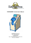
Health Robotics GmbH Via Altmann, 9A 39100 Bolzano, Italy phone +39.0471.200372 fax +39.0471.200574 mail : [email protected] CytoCare User’s Manual Type of document: Status: Revision: Technical Publication Released 1.0 - ENG Reference no: 1st release date Pages: HR-CYT-20070226 02-02-2007 60 Revision History Please verify that you are using the latest approved revision of this document. REV 1.0 - ENG DATE (dd-mm-yy) 02-02-2007 CHANGES Initial document release Cytocare User’s Manual V. 1.0 - ENG/ 02.02.2007 ) ) ) This booklet describes what information must be known by the User in order to operate CytoCare. Note The information contained in this manual is correct at the time of publication. The manufacturer reserves the right to modify and improve its products. All the technical data is subject to change without notice. Copyright In compliance with copyright protection laws, no part of this manual may be copied, photocopied, reproduced, translated or transferred to any electronic or electronically readable supports without prior authorisation. ©Copyright 2006-2007 ) Trademarks This manual makes reference to registered trademarks. The inclusion or exclusion of a name does not entail a judgement on its validity and legal status. Page II of 57 Cytocare User’s Manual V. 1.0 - ENG/ 02.02.2007 Contents Presentation of the System .......................................................................................... 5 1.1 Purpose of the System.....................................................................................................5 1.1.1 Improved Patient Safety ..........................................................................................5 1.1.2 Operator Risk Reduction ..........................................................................................5 1.1.3 Greater Compounding Process Efficiency ...................................................................5 1.2 System Composition ........................................................................................................5 2 General and Safety Precautions ................................................................................. 12 2.1 Precautions................................................................................................................... 12 2.2 Compliance with Standards ............................................................................................ 14 2.3 Presentation of the Manual Contents and Consultation Method.......................................... 15 2.4 Residual Risks............................................................................................................... 15 2.4.1 Transport and Handling ......................................................................................... 15 2.4.2 Foundation, Connection and Commissioning ............................................................ 15 3 Technical Data ............................................................................................................ 16 3.1 General Technical Data .................................................................................................. 16 4 Operation and Use ...................................................................................................... 17 4.1 Description of the System .............................................................................................. 17 4.1.1 Compounding Section.................................................................................... 18 4.1.2 Storage Section..................................................................................................... 20 4.1.3 Electrical Panel Section .......................................................................................... 23 4.1.4 Processing Waste Section ............................................................................. 23 4.2 Intended Use ................................................................................................................ 24 4.3 Environmental and Operating Limits................................................................................ 24 4.4 Operator Station ........................................................................................................... 26 4.5 Safety Devices .............................................................................................................. 27 4.6 Specific Risk and Personal Protective Equipment .............................................................. 28 4.7 User Instructions........................................................................................................... 28 4.7.1 Loading Phase....................................................................................................... 29 4.7.2 Extraction, Recognition and Weighing Phase............................................................ 31 4.7.3 Compounding Phase .............................................................................................. 33 4.7.4 Unloading Phase ................................................................................................... 34 4.8 Start-Up Procedures ...................................................................................................... 36 4.9 Stop Procedure ............................................................................................................. 40 4.9.1 Normal ................................................................................................................. 40 4.9.2 Emergency ........................................................................................................... 42 4.10 Recovery After an Emergency Stop Situation ............................................................... 42 1 Page 3 of 57 Cytocare User’s Manual V. 1.0 - ENG/ 02.02.2007 5 Maintenance and Cleaning ......................................................................................... 43 5.1 Cleaning Warnings and Preliminary Operations ................................................................ 43 5.1.1 Removing the Vial Opener...................................................................................... 45 5.1.2 Removing the Grille ............................................................................................... 46 5.1.3 Removing the Mixer Plate....................................................................................... 46 5.1.4 Removing the Upper Rim Sector ............................................................................. 47 5.1.5 Removing the UV Ceiling Light Fixture Protection ..................................................... 48 5.1.6 Removing the Bag Weighing Support ...................................................................... 49 5.1.7 Removing the Revolving Table Sectors .................................................................... 50 5.1.8 Removing the Liquid Collection Container ................................................................ 51 5.2 Cleaning the Machine .................................................................................................... 52 5.3 Periodic Sterility Inspection ............................................................................................ 53 5.4 Accidental Spillages or Contamination of the System ........................................................ 55 5.4.1 General Indications................................................................................................ 55 5.4.2 System Decontamination Procedure ........................................................................ 55 6 Key to the Main Components ..................................................................................... 57 Page 4 of 57 Cytocare User’s Manual V. 1.0 - ENG/ 02.02.2007 1 Presentation of the System 1.1 Purpose of the System The CytoCare system is designed to automate and rationalise certain fundamental phases of the cytostatic drug compounding process. CytoCare is an integrated and automated system that: • • 1.1.1 makes it possible to manage information related to prescriptions through a computerised system does away with the need for human intervention during the compounding phase Improved Patient Safety The CytoCare system makes it possible to improve patient safety in relation to the cytostatic drug compounding process. This is made possible thanks to the following functions: • • • • • 1.1.2 computerisation of the prescription process management of cytostatic drug production programming automation of cytostatic drug compounding bar code identification of the end products introduction of additional checks at the time of administration, cross checking the patient bar code against the bar code of the IV bag assigned to him/her Operator Risk Reduction The CytoCare system meets this requirement inasmuch as it makes it possible to: • • 1.1.3 do away with the need for the operators to handle the cytostatic drugs dramatically reduce the presence of personnel in the proximity of the preparation area Greater Compounding Process Efficiency The CytoCare system meets this requirement inasmuch as it makes it possible to: • • • • 1.2 completely automate the process reduce idle time programme production efficiently guarantee traceability for all operations System Composition CytoCare is a machine able to compound cytostatic drug solutions automatically in a controlled atmosphere. The machine is comprised of five sections, as can be seen in the following figure. Page 5 of 57 Cytocare User’s Manual V. 1.0 - ENG/ 02.02.2007 Figure 1: CytoCare Structure In numerical order we have the: 1. compounding section (fig. 2) 2. internal storage section and pre-loading section (fig. 3) 3. electrical compartment section 4. section housing the outlet filter, the canister (fig. 7), the computer and the control electronics 5. processing waste collection section (fig. 6) The machine has a 15” touch-screen LCD monitor, a ventilation system and five HEPA filters (H14) housed inside a specific plenum. The compounding section comprises: o dosage station o suction pump (excess solution) o vial supports o bag / infusor support o anthropomorphic robot equipped with computer vision system o device for removing the vial cap o rotating agitator o electronic balance o UV lamps Page 6 of 57 Cytocare User’s Manual V. 1.0 - ENG/ 02.02.2007 Figure 2: preparation section The storage section (fig. 3) is arranged in the form of a revolving table (carousel), allowing for the management of the material (incoming) used by the machine in the preparation of the cytostatic compounds, the prepared material and the unused material (outgoing). This table is comprised of a carousel fitted with a rim. This rim, which is an integral part of the carousel, can hold up to 27 drug vials. The carousel is comprised of 9 sections, each of which can hold: - a 3 ml syringe - a 10 ml syringe - a 50/60 ml syringe - a bag / infusor - a needle in its cover In the antechamber is a pre-loading cell, which can be used by the operator to organise and prepare the material to be loaded into the store. This cell has a perforated stainless steel work surface, characterised by a profile that guarantees the aerodynamic stability of the system and thus prevents external and internal flows from coming together. Page 7 of 57 Cytocare User’s Manual V. 1.0 - ENG/ 02.02.2007 Figure 3: storage and pre-loading section The dosage station (fig. 4) is comprised of a revolving plate fitted with three housings for syringes of 2.5/3 ml, 10 ml and 50 ml respectively. Figure 4: dosage station Page 8 of 57 Cytocare User’s Manual V. 1.0 - ENG/ 02.02.2007 These housings are comprised of a pair of jaws that hold the syringe still, while at the opposite end is an electromechanical actuator able to push the syringe plunger vertically, thus enabling suction and release of the drugs and solutions. The products are handled by an anthropomorphic robot. This robot is equipped with a video camera that makes it possible to see the actual position of the needle. The electronic balance is used for all weighing operations. The balance is equipped with: • a specific metal support that makes it possible to weigh the bags • a cover to make the measurement independent from the air flow The system is equipped with a specific revolving mixer (fig. 5, highlighted in red) for the reconstitution of drugs in powder form. This mixer is able to hold four vials of different shapes and sizes. Lastly, the compounding compartment is equipped with a device for removing the vial caps and a device (wall-mounted) for sucking excess liquid from the bags. This device comprises wall-mounted supports on which the bag can be placed during suction, preventing the formation of dead volumes inside (with the consequent extraction of air instead of the liquid contained therein). Figure 5: mixer In the part below the compounding section there is a processing waste collection section (fig. 6). The latter section contains a bin for the collection of hazardous waste. The bin stands on a mobile surface. These two chambers are connected by an automated, horizontal sliding hatch. Page 9 of 57 Cytocare User’s Manual V. 1.0 - ENG/ 02.02.2007 Figure 6: processing waste collection section The section housing the outlet filter also comprises: • a canister (fig. 7) which houses the above-mentioned filter and enables a safe replacement of the same • a Hepa filter (H14) • an industrial PC on which the machine management software (with its output on the LCD monitor) is installed • the robot controller • a container for the collection of the excess liquid extracted from the bags Figure 7: canister with bag-in / bag-out system Page 10 of 57 Cytocare User’s Manual V. 1.0 - ENG/ 02.02.2007 On the right-hand side of the machine is the section housing the electrical compartment and the activations of the motors included in the system. On the top wall (cover) of the machine are the four inlet filters, which filter the incoming air, and the outlet filter, which filters the expelled air. This is all enclosed in a plenum. The machine can be loaded using a continuous cycle, following the instructions given on the display. At the end of the loading phase, the system has the complete mapping of the store available to it, so that it knows the location of every component and manages its extraction. a) Drugs: solely and exclusively those drugs needed to make the scheduled compounds can be introduced; the insertion sequence is provided by the control unit and can be viewed on the display. The loading sequence is as follows: • Drug shown on the display (name, photo, main characteristics) • Drug positioning in correspondence to the specific housing along the top rim of the revolving table (fig. 4) b) IV infusion bags (NaCl 0.9%, Glucose 5%, Ringer's lactate): the bags containing the solutions are used to contain the final compound. The only bags that may be used are those indicated in Chapter 2, with a 50, 100, 250, 500 and 1000 ml capacity. The solutions can also be loaded independently with respect to their actual use. The procedure involves: Bag shown on the display (name, photo) Application of the specific frame (adapter supplied with the machine) to the bag Positioning of the bag, fitted with the specific adapter, in its housing (to the far right of the segment), in correspondence to the LED (the controller will stop the table) c) Syringes with needle: these are considered to be consumables and can be inserted whenever so required by the machine. The loading procedure involves: o Syringe type shown on the display (2.5 – 3, 10 and 50 ml) o Insertion of syringe in the specific housing Figure 8: circular rim onto which the drug vials are loaded Page 11 of 57 Cytocare User’s Manual V. 1.0 - ENG/ 02.02.2007 2 General and Safety Precautions 2.1 Precautions • • • • • • • Do not carry out any operations or manoeuvres if you are not absolutely sure what effect they will have. If in doubt, please contact your nearest technical assistance service or contact the manufacturer directly. The manufacturer declines all responsibility for damage caused to the machine or property in the following cases: Improper use of the machine Use of materials not expressly listed in this manual or not recognised as compatible materials by the machine manufacturer Use of non trained personnel Defects of installations Unauthorised modifications or work on the machine Use of non-original spare parts Failure to observe the regulations set out in this manual Exceptional circumstances This user’s manual has been written with the following persons in mind: Machine operators The user’s manual describes the use intended by the manufacturer and should not be used as a substitute for a sufficiently experienced operator. It simply provides guidelines in relation to the main operations to be carried out. The user’s manual must be stored carefully and be available for consultation at all times. If necessary, photocopy the pages to be employed for direct use of the machine. Before loading a syringe, make sure that: the needle is covered by its specific cover; the needle matches the model indicated in this manual; the syringe body and plunger do not show signs of any mechanical damage; the syringe plunger is pressed down so as not to create a dead volume inside the body of the syringe; Before loading a bag, make sure that: the bag matches the model indicated in this manual; the bag does not show cuts or other signs of wear on the external surface; the neck of the bag is not damaged in any way; WARNING The user’s manual describes the techniques in place at the time of system construction. The manufacturer reserves the right to make any changes believed to be necessary to the machines and the users’ manuals, without the need for prior notice or replacing Page 12 of 57 Cytocare User’s Manual V. 1.0 - ENG/ 02.02.2007 IMPORTANT WARNING The machine may only be operated with the materials listed below: Bags: 50 ml, 100ml, 250ml, 500ml, 1000 ml, Baxter mod. Viaflo Syringes: 50/60 ml, 10 ml and 2.5 ml, Becton Dickinson mod. Plastipak Needles: Vented Needle Baxa mod. Two-Fer short 13mm/16G (purple) Infusors: Baxter, mod. Infusor LV2 Infusor adapters: BBraun, Injection Cap mod. IN2000 Special waste containers: AP Medical mod. SB 301 Printer labels: Seiko (Smart Label Printer), Type SLP-TMRL 28x51mm WARNING The use of other materials could cause operating problems, damage to the machine, dosage errors and create hazardous conditions for the operators, the patients and the environment. Before loading a drug, make sure that: • the drug label is in good condition, meaning that the drug can be correctly identified • the vial, containing the cytotoxic drug, is perfectly intact throughout Page 13 of 57 Cytocare User’s Manual V. 1.0 - ENG/ 02.02.2007 2.2 Compliance with Standards • The system complies with the UL 61010 standard (Safety Requirements for Electrical Equipment for Measurement, Control, and Laboratory Use). • The system complies with the UL 60601 standard (Medical Electrical Equipment). • The system meets the requirements set out in the EN 12469 standard (Biotechnology. Performance criteria for microbiological safety cabinets) as regards the parts applicable to the case in hand: Intactness of the HEPA filters Product protection Casing intactness test External seal capacity test (KI discus test) Pre-loading section seal capacity test Disinfection requirements test • The system meets the requirements set out in the DIN 12980 standard (Laboratory furniture – Cabinets for handling cytotoxic drugs) as regards the parts applicable to the case in hand: Intactness of the HEPA filters Product protection Casing intactness test External seal capacity test (KI discus test) Pre-loading section seal capacity test Disinfection requirements test Mechanical resistance test • The machine internal air quality is certified in compliance with the EN ISO 14644 standard (Cleanrooms and associated controlled environments) as regards the following procedure: Particle count test • The system meets the requirements set out in the DIN EN 12296 standard (Biotechnology Equipment - Guidance on testing procedures for cleanability) as regards the parts applicable to the case in hand: Cleaning requirements test (rounded corners and edges) • The system is FDA-classified as a “Pharmacy Compounding System”, premarket approval exempt. • The design, development and manufacturing of this system comply with the GAMP (Good Automated Manufacturing Practice) guidelines. Page 14 of 57 Cytocare User’s Manual V. 1.0 - ENG/ 02.02.2007 2.3 Presentation of the Manual Contents and Consultation Method This document has been written for the end user (laboratory technician, pharmacist, healthcare operator) and is intended to provide all the information necessary for the safe operation of the system, in keeping with the manufacturer’s intended use. 2.4 Residual Risks 2.4.1 Transport and Handling The system must be fully assembled to be transported, with the exception of the following mechanical assemblies: Plenum, inlet filters Air passage pipes External bar code reader Certain internal tools 15" touch-screen LCD monitor This system has been developed for use as a fixed installation. However, it is fitted with four wheels that mean it can be moved over short distances for positioning purposes. 2.4.2 Foundation, Connection and Commissioning The machine must be positioned on a rigid, levelled and sufficiently strong horizontal surface. It is advisable to ensure that the machine has been installed and positioned in keeping with the instructions provided in the pre-installation guide. In the case of differences, please contact the manufacturer. To this regard, it is best to check: - that all the cover panels are correctly positioned and secured - that the tools and the related accessories are correctly assembled - that the doors and related locks are in good working order and do not show signs of wear The machine may only be started after these checks have been carried out. If the system fails to start, it is advisable to check that the network and power cables are correctly connected and do not show signs of wear. Please contact the manufacturer if required. Page 15 of 57 Cytocare User’s Manual V. 1.0 - ENG/ 02.02.2007 3 3.1 Technical Data General Technical Data The following table provides a summary of the main system characteristics: Electrical Characteristics Value Electric cabinet dimensions 968x470x1365 Power supply type 3P+PE Earth connection type TN-C Power supply voltage (linked) 400 – 480 V Frequency 50 – 60 Hz Installed power 12 KW Incoming line protection 24 A Station Data Value Dimensions (LxDxH) 2150x1600x2400 mm Weight 1200 (1500) kg Electrical Panel Data Value Dimensions (LxDxH) 968x22x1365 mm Electrical panel weight 30 Kg Installed electric power 12 KW Centralised suction system 200 mm (outlet diameter) Air flow 700 m3 / h Table 1: general technical data Noise Emission The continuous noise level produced by the system is under 70 dB, with the measurement taken by placing the measurement instrument at a distance of 0.50 m from the operator panel and at a height of 1.50 m. Page 16 of 57 Cytocare User’s Manual V. 1.0 - ENG/ 02.02.2007 4 Operation and Use 4.1 Description of the System The CytoCare system (fig. 9) is characterised by a frame measuring 2150x1600x2400, comprising the pipes located at the back of the system. As already mentioned, the machine is comprised of five sections: compounding / preparation section (fig. 10) storage and pre-loading section electrical panel section section housing the HEPA outlet filter, the canister, the PC on which the machine software is installed and the robot controller refuse and processing waste collection section The machine has a 15” touch-screen LCD monitor, an aspirator, four HEPA inlet filters and an additional outlet filter. Figure 9: CytoCare system Page 17 of 57 Cytocare User’s Manual V. 1.0 - ENG/ 02.02.2007 4.1.1 Compounding Section The compounds are made in this section. The compounding process generally involves: insertion of a drug in an IV solution insertion of a drug in an infusor with the possible addition of an IV solution Figure 10: compounding / preparation section If the drug is a powder, the system will activate a special procedure for the correct reconstitution of the drug in the liquid phase. The system is able to handle: o multiple compounds starting from a single drug vial o compounds that require the use of several vials of the same drug The working area has been developed to guarantee sterility, using a filtering system with dedicated absolute filters and a correct air flow in the air recirculation circuit. All the components that allow for correct system operation are positioned inside the area: a) anthropomorphic robot that moves the syringes and bags within the sterile area b) dedicated positions to accelerate the execution of certain elementary operations, whilst ensuring maximum safety and precision: - precision balance for weighing - dosage device for extraction through the use of disposable syringes - needle position detection device - multipurpose drug temporary storage stations - drug vial housings, in the case of compounds requiring several vials of the same drug - materials used during compounding - positions dedicated to the removal of the protective cap from the vials Page 18 of 57 Cytocare User’s Manual V. 1.0 - ENG/ 02.02.2007 Figure 11: electronic balance The compounding section communicates with the storage section and with the processing waste section through an opening. Air filtration in both areas is guaranteed by absolute filters. Figure 12: needle position detection device Page 19 of 57 Cytocare User’s Manual V. 1.0 - ENG/ 02.02.2007 Figure 13: internal bar code reader 4.1.2 Storage Section The storage section is arranged in the form of a revolving table, allowing for the management of the incoming material used by the machine in the preparation of the cytostatic compounds, the prepared material and the unused material. The system requires operator intervention during the loading phase (drugs, syringes, infusors and bags) and the finished product unloading phase (cytostatic drug-based solutions ready for use). Moreover, the operator uses a monitor to guide him/her through the loading phase. The monitor makes it possible to check the machine status, intervening when anomalies occur, which are promptly signalled by the machine by means of diagnostic messages. Figure 14: storage section arranged in the form of a revolving table Page 20 of 57 Cytocare User’s Manual V. 1.0 - ENG/ 02.02.2007 Each section of the revolving table includes the following housings: - 2.5-3 ml syringe - 10 ml syringe - 50 ml syringe - suction needle - bag/infusor - drug vials Figure 15: 15” touch-screen monitor For safety reasons, this section includes a number of operator aids, including: • Touch-screen LCD monitor: to provide the operator with the information needed to use the machine loading list processing list information on the drugs (including a photo of the vial/bag for an immediate visual check) information on processing status • Manual bar code reader (external) and automatic bar code reader (internal) (fig. 13): used for the univocal identification of the drug / bag product code • Position sensors: to check for the presence of the vial • Recognition system (computer vision): makes it possible to recognise the drug vials (fig. 16) Page 21 of 57 Cytocare User’s Manual V. 1.0 - ENG/ 02.02.2007 Figure 16: vial recognition system The revolving table carries the vials, the bags/infusors and the syringes to the opening connecting to the sterile compartment, where they are extracted by the anthropomorphic robot housed in the compounding section. Figure 17: position sensors Page 22 of 57 Cytocare User’s Manual V. 1.0 - ENG/ 02.02.2007 4.1.3 Electrical Panel Section The area hosting the electrical panel contains all the electronic components necessary for the control and operation of the machine. It includes an electrical panel for signal control, motorised doors between the compounding section and the processing waste section, protection circuits and a service interface for maintenance operations. Outlet Filter Section This section houses the outlet filter inside the canister, the PC on which the machine software is installed and the robot controller Figure 18: outlet filter section 4.1.4 Processing Waste Section This section hosts the rigid removable container (fig. 19) into which the processing waste (vials, syringes, bags, etc.) is discarded through the shuttered opening. The internal part of the container is hermetically coupled to the preparation chamber during the process. The container is automatically closed and sealed upon reaching a level set by the operator. Page 23 of 57 Cytocare User’s Manual V. 1.0 - ENG/ 02.02.2007 Figure 19: waste bin 4.2 Intended Use CytoCare is an automatic cytostatic compound preparation system. This system is able to handle 2.5-3 ml, 10 ml and 50 ml syringes, vials containing drugs or solutions, intravenous infusion bags and infusors. Moreover, thanks to the use of particular technological solutions, such as the “frame” (adapter for safely gripping the bags) and above all the flexibility offered by the system, it is possible to consider using the system for the preparation of other drug types (i.e. antibiotics, pain relief, etc.) through the introduction of suitable hardware and software upgrades. 4.3 Environmental and Operating Limits The system must be housed in a room with: o suitable air circulation; the air conditioning system must be able to supply the 700 m³/h required for the operation of the machine o dedicated power supply circuit with differential protection o socket for connection to the LAN network o external air outlet system The following table provides a summary of the environmental conditions required for the operation and storage of the system. Page 24 of 57 Cytocare User’s Manual V. 1.0 - ENG/ 02.02.2007 Environmental Conditions (operation) Temperature Humidity Maximum height above sea level Environmental Conditions (storage) Temperature Humidity Maximum height above sea level Value 10 - 25°C 5 - 85% 2000 m Value 0 - 55 °C 5 - 85% 2000 m Table 2: environmental conditions CytoCare must be positioned well away from busy corridors, doors, ventilators, ventilation grilles, hoods and any other air-conditioning devices that could disturb the normal air flow. All windows in the room must be kept closed. Figure 20 shows the zones (inside the room) where the CytoCare system should preferably be positioned. The minimum clearance between the highest point of the machine and the ceiling is 250 mm. This will enable an adequate air flow and repairs to the machinery if necessary. It is necessary to keep a minimum clearance of 800 mm from the right-hand wall (electrical panel side) and 100 mm from the left-hand wall. A clearance of 700 mm is recommended behind the machine. Figure 20: CytoCare positioning Page 25 of 57 Cytocare User’s Manual V. 1.0 - ENG/ 02.02.2007 4.4 Operator Station The user (healthcare operator, pharmacist, etc.) can access the machine through the opening in the front part of the pre-loading section (fig. 21). The opening is of a sufficient size to allow the introduction of both hands. This preloading section has a surface on which it is possible to prepare the material to be loaded into the store, and is characterised by a vertical air flow filtered by HEPA absolute filters. Figure 21: pre-loading section The particular air circulation configuration makes it possible to prevent the internal and external flow from mixing, as confirmed by the simulation illustrated in fig. 22. This simulation clearly shows how, thanks to the particular shape of the surface and the size of the sterile air circulation system, filtered by the front HEPA filter, a descending vertical jet is created. This “blade of air” actually prevents the air sucked in from the external environment from penetrating the chamber interior. In addition to preventing mixing, the jet flow laps the surface, ensuring continuous cleaning of the operator work zone. The three zones involved – external environment, pre-loading section and loading chamber – are effectively isolated. The operator can access the storage section (loading/unloading) through a specific opening in the wall that separates this section from the pre-loading section. This opening has a horizontal sliding door and is equipped with an interlock switch, thanks to which it is possible to guarantee maximum operator safety. The revolving table can therefore be activated only when the door is closed. The latter, in its turn, cannot be enabled while the table is moving. In the event of accidental spillages in the compounding section, once operation has been suspended, the operator can access the section through the front Lexan™ door, protected by electromagnetic switches. Lastly, the operator can access the unloading section (processing waste management) Page 26 of 57 Cytocare User’s Manual V. 1.0 - ENG/ 02.02.2007 when the system requires the hazardous waste container to be replaced. This section is also protected by electromagnetic switches. Figure 22: air circulation diagram – pre-loading section 4.5 Safety Devices The CytoCare o o o o system is fitted with the following safety devices: Magnetic limit switches (sensors) Safety interlock switches (fig. 23) Emergency device, category 4 Lexan™, 8 mm thick Figure 23: safety interlock switch Page 27 of 57 Cytocare User’s Manual V. 1.0 - ENG/ 02.02.2007 4.6 Specific Risk and Personal Protective Equipment In order to reduce the specific risk linked to this system to the minimum, it is advisable to use the following personal protective equipment (PPE): CE mark gloves (standard EN 374) category 3 and 4 clothing (340, 369 and 465) semi-mask with dust filter (class p3) or filter facepiece (class ffp3sl) visor or equivalent (166) 4.7 User Instructions The machine follows a precise operating cycle, comprised of the following phases: Switch-on Loading Recognition and weighing Compounding Unloading Switch-off Figure 24: CytoCare Page 28 of 57 Cytocare User’s Manual V. 1.0 - ENG/ 02.02.2007 Switch-on Loading phase Prescription acquisition Recognition, weighing and compounding Unloading phase Another compound? YES NO Switch-off Figure 25: generic cycle flow chart 4.7.1 Loading Phase To start the machine for a compound preparation cycle you need to: 1. launch the machine management application 2. call up the “LOAD DRUGS” mode onto the touch-screen Page 29 of 57 Cytocare User’s Manual V. 1.0 - ENG/ 02.02.2007 3. select the “START” option on this screen. At this point, the machine will load the prescriptions for the compounds to be prepared Figure 25: loading phase screen 4. once the prescription has been loaded, a screen appears on the monitor displaying an image of the vial/IV bag/infusor/syringe/needle (fig. 25, e.g. needle) a) b) c) d) Figure 26: loading materials Page 30 of 57 Cytocare User’s Manual V. 1.0 - ENG/ 02.02.2007 5. make sure that the product you are about to load corresponds to that displayed on the monitor 6. load the afore-mentioned vial/bag/infusor/syringe/needle into the specific housing 7. repeat the operations indicated in points 4-6 for each item 8. to complete the loading phase, close the metal door (see fig. 27 a-b) 9. select “STOP” a) b) Figure 27: closure of the horizontal sliding door 4.7.2 Extraction, Recognition and Weighing Phase Once the loading door has been closed, the machine can continue operations. The bag recognition process takes place thanks to a bar code reader built into one of the internal walls of the storage section. The robot begins by taking the syringe and positioning it on the dosage disc. Once placed in the specific housing, the robot removes and discards the needle cover, placing it in the bin. At this point, the robot takes the vials containing the drug, carrying them to the precision balance where they are weighed for the first time. The afore-mentioned vials are then positioned on a shaped support (fig. 28-b). a) b) Figure 28: a) weighing; b) positioning a vial on the shaped support Page 31 of 57 Cytocare User’s Manual V. 1.0 - ENG/ 02.02.2007 Figure 29: shaped support for bag/infusor The robot then takes the bag, repeating the operations described above for the drug vials in the same order. After doing this, the robot takes a syringe from the revolving table/store and puts it into position. It is best to remember that the following are present in the compounding section: a bag and infusor support (close-up in fig. 29) two supports/shelves on which the vials can be positioned (fig. 30) Figure 30: shaped supports for vials Page 32 of 57 Cytocare User’s Manual V. 1.0 - ENG/ 02.02.2007 4.7.3 Compounding Phase During the procedure in the compounding chamber: • the vials containing the drug are positioned on one of the two supports (fig. 30) • the syringe is housed in the dedicated housing on the dosage disc (fig. 32) • • the bag is positioned on the dedicated support (on the right in fig. 29) the infusor is positioned on the dedicated support (idem) Figure 31: positioning the syringe on the dosage disc During this phase, the robot takes the vials and carries them, one by one (after removing and discarding the protective cap that covers the lid that can be punctured), to the dosage station. Here, the syringe, positioned with the needle pointing upwards (fig. 33), sucks up the desired quantity of the drug. Figure 32: extracting the drug from the vial Page 33 of 57 Cytocare User’s Manual V. 1.0 - ENG/ 02.02.2007 Once suction is complete, there are two possible scenarios: 1. if the drug has been completely used up, the robot will discard the vial, placing it in the waste collection bin 2. if this is not the case, the vial will be moved to a specific support, where it will remain until it is reused At the same time, the robot takes the bag from the specific support and places it in correspondence to the excess liquid suction device. This device is comprised of: • rods on which the bag is placed (facing downwards) • an aspirator fitted with a needle, to which the bag is connected in order to conduct the extraction (fig. 34) Once the solution extraction is completed, the bag is weighed again, then transported into the proximity of the dosage disc, where the previously extracted drug is injected. Figure 33: aspirator 4.7.4 Unloading Phase At the end of the compounding phase, there is a compounding section emptying phase. If, on the other hand, compounding has begun but has then been stopped, the material in the compounding section is discarded as follows: - the syringe is discarded into the hazardous waste bin; - the bag/infusor is taken back to the revolving table/store - the drug vials remain in their supports, or they may be extracted by the operator (by selecting the "UNLOAD ALL BOTTLES" function) To this regard, after ascertaining that the compounding is complete (you need to select "STOP" in the "MAKING..." mode), it will be possible to open the door that communicates with the pre-loading section and extract the material available on the revolving store. At the end of every cycle, the robot can replace the suction needle: this parameter can be set by the user. Page 34 of 57 Cytocare User’s Manual V. 1.0 - ENG/ 02.02.2007 Figure 34: connection hatch between the compounding section and the waste bin section a) b) c) d) Figure 35: replacement of the special waste container Once work is over, or whenever necessary (when the waste level exceeds the level set by the operator), it is necessary to remove and/or replace the hazardous waste container. To do so you need to select “UNLOAD RECYCLE BIN” mode. Page 35 of 57 Cytocare User’s Manual V. 1.0 - ENG/ 02.02.2007 Consequently: 1. the container is disconnected from the communication hatch (linked to the processing area) 2. the lid is positioned over the container opening using a horizontal sliding mechanism 3. the container is pushed upwards (pushed to the limit) 4. the lid is sealed to the container (sealing material is placed around the edges of the lid). Once the bin has been sealed, the user must: o open the door o release the two catches (in the direction indicated in fig. 36-c) o slowly extract the container o press the lid down firmly to lock it permanently into place WARNING 4.8 Before extracting the container, make sure that the catches have been released and/or that they do not obstruct the container removal. Start-Up Procedures To start up the machine, turn the switch/knob on the side metal panel in a clockwise direction (fig. 37 a-c). After doing so, you will notice a flashing LED come on, situated on the push button and status light panel. This red LED indicates the emergency status of the machine. a) b) c) d) Figure 36: CytoCare start-up Page 36 of 57 Cytocare User’s Manual V. 1.0 - ENG/ 02.02.2007 In general, the system goes into emergency status in the following cases: • First start-up • If the red emergency button has been pressed So that the machine can proceed with the loading phase, you need to turn the key positioned in the push button panel by 45° in a clockwise direction. This area hosts the status LEDs, the emergency button and the system release key. The cycle is instantly interrupted upon pressing the emergency button WARNING USB Release key Status LEDs Emergency button Figure 37: start/stop emergency pushbutton panel Page 37 of 57 Cytocare User’s Manual V. 1.0 - ENG/ 02.02.2007 To restore normal system operation, you need: to turn the emergency button in an anticlockwise direction turn the release key (as indicated in fig. 39 b-c): to this regard, you will observe that the red LED switches off and the white LED comes on. a) b) c) d) Figure 38: system start-up - status lights It will be possible to view the normal operating system loading procedure on the touchscreen LCD display (Microsoft Windows XP, fig. 40-a). The machine management software is automatically loaded whenever the system is started. The software in question envisages three different user types (and thus 3 different access levels): Administrator Authorised maintenance personnel User (healthcare operator) The operator who accesses the system as “administrator” has access to all the machine functions. The operator who accesses the system as “maintenance personnel” has access to the robot functions and manual controls. The operator who accesses the system as “user” has access to the main system functions (those that make it possible to complete any cycle). Moreover, he/she has access to certain manual robot controls (remote control console, fig. 46) in addition to the machine cleaning controls. The healthcare operator can access the system as “user”. To this regard, to proceed with loading the above-mentioned programme, a template for logging into the CytoCare system management software appears on the display. Page 38 of 57 Cytocare User’s Manual V. 1.0 - ENG/ 02.02.2007 a) b) c) d) Figure 39: loading the CytoCare software To access the software, you need to enter the correct alphanumerical codes in the "user name" and "password" boxes. At this point, the machine can complete the software loading phase necessary for its correct operation. Figure 40: main screen – CytoCare software The initial software screen will appear on the LCD display (fig. 41). The screen features four main buttons (functions): o Load recycle bin o Make preparation o Unload all bottles o Unload recycle bin Page 39 of 57 Cytocare User’s Manual V. 1.0 - ENG/ 02.02.2007 A drop-menu is situated at the top of the software interface, from which you can select the following options: 1. “SELECT CYCLE” (main screen as above) 2. “MAKE PREPARATION” (cytostatic drug compounding process) 3. “LOADING DRUGS/SOLUTIONS/INFUSORS” (loading material) 4. “SERVICE” (maintenance options) 4.9 Stop Procedure 4.9.1 Normal To stop machine operation, you initially need to shut down the operating system installed on the machine. This operation can be carried out directly from the touchscreen. The procedure involves the following steps: 1. close the system management application by calling up the “EXIT” option on the touch-screen (as indicated in fig. 42) Figure 41: CytoCare management software shut-down 2. confirm the software shut-down 3. select the “START” option from the main Windows menu (in the bottom left corner of the desktop) 4. select “SHUT DOWN” 5. select “SHUT DOWN” from the options menu 6. confirm by pressing “OK” 7. wait until the operating system shut-down procedure is complete 8. turn the ON/OFF knob on the side panel by 90° in an anticlockwise direction (fig. 44) 9. at this point you will hear a repeating acoustic signal that indicates the need to stop the continuity unit (UPS) 10. lift the hatch that conceals the continuity unit stop button (as illustrated in fig. 43 a-c). 11. press the button until you hear a double acoustic alarm Page 40 of 57 Cytocare User’s Manual V. 1.0 - ENG/ 02.02.2007 a) b) c) d) Figure 42: stopping the continuity unit a) b) c) d) Figure 43: stopping the CytoCare system The system is also equipped with: Two UV lamps installed on the ceiling of the compounding section One UV lamp installed on the ceiling of the storage section Page 41 of 57 Cytocare User’s Manual V. 1.0 - ENG/ 02.02.2007 One UV lamp, built into the metal catch to apply to the pre-loading section access window These lamps are activated within a certain period of time after the system has been shut down. This interval can be defined by the system administrator. This operation ensures that the machine interior is kept sterile. We recommend cleaning and disinfecting the system interior thoroughly before activating the UV lamps. WARNING 4.9.2 Emergency If there is a temporary or long-term power cut, the UPS unit will be activated, making it possible to switch off the machine safely. This involves the implementation of the following operations: Saving all the data related to the current compounds (and thus the machine status) Safe machine shut-down 4.10 Recovery After an Emergency Stop Situation Following an emergency stop, the machine automatically recovers its status before the interruption. The user simply has to start up the machine. Page 42 of 57 Cytocare User’s Manual V. 1.0 - ENG/ 02.02.2007 5 Maintenance and Cleaning 5.1 Cleaning Warnings and Preliminary Operations In order to guarantee the high quality of the mixed products, it is necessary to clean and disinfect the machine on a daily basis. For this purpose, as soon as the daily dose compounding cycles have been completed, you should regularly and systematically clean all the accessible parts of the machine. The level of cleanliness and sterility inside the machine is strongly conditioned by the cleanliness of the room in which it is installed and of the objects introduced into the room during the processing phases. All the materials must be handled using suitable sterile disposable protective equipment (white coat, mask, cap, gloves, goggles). To carry out the cleaning operations in complete safety you should: • Call up the “CLEANING” mode onto the touch-screen and start it up. When in this mode, the robot is positioned so as to increase the range of action of the operator responsible for carrying out the cleaning operations. Figure 44: cleaning menu • • • Use suitable sterile disposable protective equipment (white coat, mask, cap, gloves, goggles) During decontamination operations, make sure that the suction system is always in operation; if this is not the case, stop cleaning immediately, close all the machine doors and call the technical assistance service. Do not carry out cleaning operations when the machine is switched off Make sure that all the material needed to carry out the cleaning operations can be found in the vicinity of the system Page 43 of 57 Cytocare User’s Manual V. 1.0 - ENG/ 02.02.2007 • • • In order to reach all the internal areas of the machine with ease, you need to remove the following tools from their housings: Vials opener and mixer plate Grille – compounding section UV lamp fitting protection – compounding section Bag weighing adapter Revolving table top rim sectors Revolving table sectors Place all the used material (gloves, gauze, cotton, disposable cloths and any other non-sharp objects, including disposable personal protective equipment) in suitable, easily identifiable containers (rigid external structure and plastic lining with double lock), marked as C.W. (Clinical Waste) to be sent to the incinerator. Avoid the use of sodium hypochlorite inasmuch as it can corrode the metal surfaces of the machine The operator (who accesses the system as the “user”) has access to some machine cleaning controls. WARNING Figure 45: robot remote control console If the robot is unable to return to the home (rest) position automatically, the operator can use the manual controls found on the console (fig. 46). By clicking on the “HOME” button and then on the “STOP / MOVE” button in sequence, the robot will return to the rest position, taking the shortest route. When used in this mode, the robot is unable to avoid any obstacles it may meet on its journey. Because of this, when the robot encounters an obstacle you will need to click on “MOVE / STOP”. To make movements along a single axis, use the buttons on the console keypad. X, Y and Z represent the 3 main axes, while RX, RY and RZ make it possible to rotate around the above axes. By using these controls, it is possible to make movements and turns in both directions (positive and negative). Page 44 of 57 Cytocare User’s Manual V. 1.0 - ENG/ 02.02.2007 Note: for handling the detergents and/or disinfectants described above in a safe way, refer to the technical information and safety information provided by the respective manufacturers. In order to simplify the cleaning operations, it is necessary to dismantle some tools found in the compounding section and storage section. To this regard, a series of photographs have been provided below to illustrate the above-mentioned dismantling procedures. WARNING 5.1.1 Make sure that the removed tools do not knock any other components or the framework of the machine. In the event of an accidental knock, check for any damage immediately and contact the manufacturer if necessary. Do not use work tools to remove the machine internal components. If it is not possible to proceed with the dismantlement operations, please contact the manufacturer Removing the Vial Opener To remove the vial opener: 1. grasp the neck of the tool in your left hand, while holding the base of the tool in your right hand (fig. 47-a) 2. turn the body of the tool by approximately 90° in a clockwise direction (fig. 47-b) 3. slowly remove the cylindrical body of the tool (fig. 47-c) a) c) b) Figure 46: removal of the device for removing the vial caps Page 45 of 57 Cytocare User’s Manual V. 1.0 - ENG/ 02.02.2007 5.1.2 Removing the Grille The outer grille found in the compounding section is comprised of four segments. To remove each of the above segments: 1. find the knobs used to remove the grille (fig. 48-a) 2. grasp the two knobs with both hands (knobs are found on each segment of the grille) (fig. 48-b) 3. remove the grille (with an upwards motion) (fig. 48-c) a) b) c) Figure 47: removal of the grille – compounding section 5.1.3 Removing the Mixer Plate To remove the mixer plate: 1. Grasp the centre of the plate with one hand and the edge of the plate with the other (fig. 49-a) 2. Remove the plate starting from the outer part (fig. 49-b) 3. Complete the removal of the mixer plate, making sure that you do not damage the structure (fig. 49-c) a) b) c) Figure 48: removing the mixer plate Page 46 of 57 Cytocare User’s Manual V. 1.0 - ENG/ 02.02.2007 5.1.4 Removing the Upper Rim Sector The revolving table used to manage the store is comprised of a frame and a series of easily removable accessories. There are nine sectors mounted on the frame, each of which can house the materials necessary for completing a compound. The whole is stabilised by the use of a catch. Lastly, installed on the outer edge of the table, is an upper rim comprised of nine sectors, which can be individually removed / installed. To remove a sector of the rim: 1. grasp the edge (nearest to the operator) of the sector (fig. 50 a-b) 2. lift this edge (exercising a slight pressure towards the inside the table) (fig. 50-c) 3. gently lift the entire sector (fig. 50-d) 4. repeat the same procedure for all the other sectors a) b) c) d) Figure 49: removing a rim sector Page 47 of 57 Cytocare User’s Manual V. 1.0 - ENG/ 02.02.2007 5.1.5 Removing the UV Ceiling Light Fixture Protection There are two ceiling light fixtures in the processing area, each of which houses a UV-C lamp and a light respectively. Each of the ceiling light fixtures is protected by a Lexan™ panel, secured by means of an expansion catch. This panel: prevents even tiny amounts of aerosols from contaminating the inside of the ceiling light fixture prevents even tiny amounts of aerosols from damaging the components housed inside the ceiling light fixture does not allow the passage of UV-C rays Because of this, once daily cleaning is over, it is necessary to dismantle the above panels as follows (as illustrated in fig. 51 a-d). To this end you need: 1. To loosen the expansion catch that secures the panel to the wall 2. Remove the panel from the wall (working first on one side then on the other) 3. Slowly remove the panel a) b) c) d) Figure 50: removing the UV ceiling light fixture protection Page 48 of 57 Cytocare User’s Manual V. 1.0 - ENG/ 02.02.2007 5.1.6 Removing the Bag Weighing Support To remove the bag weighing support: 1. grip the support (fig. 52-a) 2. slowly lift the support (first on one side, then on the other) (fig. 52 b-c) 3. slowly remove the support, drawing it towards yourself (fig. 52-d) WARNING Make sure that the balance is not damaged and/or moved during the removal of the bag weighting support Once maintenance is completed, make sure that you mount the bag support correctly a) b) c) d) Figure 51: removing the bag weighing adapter Page 49 of 57 Cytocare User’s Manual V. 1.0 - ENG/ 02.02.2007 5.1.7 Removing the Revolving Table Sectors To remove the sectors that hold the housings for the material to be loaded, loosen the cylindrical lock positioned at the top of the revolving table shaft. To remove the various sectors you (first) need to: 1. unscrew the lock in an anticlockwise direction (without removing it) (fig. 53 a-b) 2. identify the protuberance by means of which the related sector is secured (fig. 53-c) 3. turn the disc (and then the protuberance) in an anticlockwise direction so as to bring the protuberance into correspondence with the gap between two segments (fig. 53-c, 53-d) 4. grip the individual sector in correspondence to the central opening (fig. 54-a) 5. gently lift the above sector (fig. 54-b) a) b) d) c) Figure 52: removing the lock – storage table Page 50 of 57 Cytocare User’s Manual V. 1.0 - ENG/ 02.02.2007 a) b) Figure 53: removing the revolving table sector 5.1.8 Removing the Liquid Collection Container Lastly, here is the procedure for removing and emptying the container used to collect the excess content extracted from the IV bags. 1. exercise slight pressure on the nozzle that connects the pipe to the container (fig. 55-a) 2. extract the pipe, keeping pressure on the above nozzle (fig. 55-b-c) It is now possible: to replace the container with a new one or simply empty it After carrying out these operations, the container should be positioned in the dedicated housing, then the pipe should be connected. b) a) c) Figure 54: maintenance work on the container used to collect the liquid from the aspirator WARNING Make sure that the tools removed are stored in a safe place Before closing the machine, make sure that all the components have been correctly assembled Page 51 of 57 Cytocare User’s Manual V. 1.0 - ENG/ 02.02.2007 5.2 Cleaning the Machine The recommended procedure is described below. In order to keep the machine interior as clean and sterile as possible, we recommend following the operations described in the exact order in which they are written. 1. Call up the “CLEANING” mode onto the touch-screen and start it up. Wait for the consent signal to appear. 2. Open the front hatch of the machine loading section. 3. Dismantle all the accessories, as described in the previous paragraphs 4. Clean all the accessible parts and the accessories with gauze soaked in a detergent / disinfectant solution (for example a 4% Saniquat water solution or similar quaternary ammonium salt-based product). Pay particular attention to the: a. drug vial loading system (upper rim sectors); b. syringe, bag/infusor and needle loading system (revolving table sectors); c. accessible surfaces (walls, transparent Lexan™ panels, metal casings, etc.). 5. Once you have finished cleaning the loading compartment, make sure that both the doors (large hatch and sliding door) are closed. 6. Open the front door of the compounding section and clean all the accessible parts with gauze soaked in the detergent / disinfectant solution described above. Proceed in the following order: a. robotic arm, jaws and video camera (with the exception of the lens, which is very delicate, making it necessary to be extremely careful); b. plastic cap removal system; c. syringe support system and dosage disc; d. compounding compartment surface; e. side shelves and other shaped supports; f. suction system; g. balance, mixer and other accessories; h. accessible surfaces (walls, transparent Lexan™ panels, etc.). 7. Once you have finished cleaning using the quaternary ammonium solution, repeat the procedure described from points 2 to 6, using gauze (avoiding cotton or rags that leave a residue) soaked in 70% isopropyl alcohol, working from top to bottom. 8. At the end of the cleaning operations, we recommend using a 70% isopropyl alcohol spray on all the surfaces, making sure that they remain damp for at least 5 minutes. 9. Close the machine doors and wait for all the internal surfaces to dry completely. 10. Start the timed sterility maintenance cycle with the UVC lamps, making sure that no operators have access to the room where the machine is installed during the set operating period (we recommend placing suitable warning signs outside the room). Page 52 of 57 Cytocare User’s Manual V. 1.0 - ENG/ 02.02.2007 5.3 Periodic Sterility Inspection To check the adequacy of the cleaning and disinfection measures adopted, we suggest the adoption of a periodic machine interior sterility inspection protocol. Most healthcare facilities normally adopt sterility inspection protocols. These same protocols can be easily adapted for use with the CytoCare system. If the healthcare facility has not yet developed a similar protocol, a number of indications are provided below that could be used as a starting point for the development of an inspection procedure. Important note: The following tests involve opening the loading compartment and the compounding compartment. For obvious safety reasons, they must be carried out using test vials only, containing a physiological solution or water for injectable compounds. Health Robotics will be pleased to provide users information regarding products suitable for this purpose. Part 1: Compounding Section Sterility Purpose: Determination of the level of microbial contamination in the drug mixing area. Method: Determination of the total microbial load by means of contact and air samples applied to a culture medium, with subsequent incubation and direct UFC count. Materials: Contact plates with general medium (i.e. trypticase, soy, agar, etc.), diameter 55 – 60 mm, or similar Plates with general medium (i.e. trypticase, soy, agar-blood, etc.), diameter 100 mm, or similar Procedure: Identify the sampling points in the compounding section, as described below: Contact samples: lower surface of the compounding chamber (under the dosage station) vial support shelves plate and shaped support (for the bags/infusors) of the balance needle Air samples: lower surface of the compounding chamber (centre) vial support shelves plate and shaped support (for the bags/infusors) of the balance lower surface of the compounding chamber (under the dosage station) needle Preliminary operations: 1. On the day prior to the test, clean and disinfect the compounding chamber and loading compartment thoroughly, adopting the necessary precautions to reduce the entry of contaminated air from the surrounding environment as far as possible. 2. Activate the night sterility maintenance system (UV lamps). Method of execution: Page 53 of 57 Cytocare User’s Manual V. 1.0 - ENG/ 02.02.2007 1. Start up the dosage procedure, setting 20 compounds and loading the related materials. The loading operations should be carried out by adopting the usual precautions to minimise internal contamination of the machine. 2. Wait for the above preparations to be completed. 3. Insert the plates into the compounding section through the front opening for manual access, taking care to prevent accidental contamination of the same. 4. Take the contact samples in sequence, respecting the order given above, resting the culture medium gently against the surface for 10 seconds. 5. Take the air samples, positioning the plates and leaving them exposed for 60’. 6. Send the samples to the laboratory for incubation and reading Part 2: Sterility of Surfaces in Contact with the Mixed Liquids Purpose: To check the sterility of the surfaces in direct or indirect contact with the mixed liquids (needles, lids that can be perforated). Method: Determination of the total microbial load by means of contact samples applied to a culture medium, with subsequent incubation and direct UFC count. Materials: Contact plates with general medium (i.e. trypticase, soy, agar, etc.), diameter 55 – 60 mm, or similar Procedure: Preliminary operations: 1. Clean and disinfect the compounding chamber and loading compartment thoroughly, adopting the necessary precautions to reduce the entry of contaminated air from the surrounding environment as far as possible. 2. Activate the night sterility maintenance system (UV lamps). Method of execution: 1. Start up the dosage procedure, setting 40 compounds and loading the related materials. The loading operations should be carried out by adopting the usual precautions to minimise internal contamination of the machine. 2. Stop the machine during preparations Nos. 10, 20, 30 and 40 in order to take the samples as described below. 3. Insert the plates into the compounding section through the front opening for manual access, taking care to prevent accidental contamination of the same. 4. Take the contact samples, respecting the order given below, resting the culture medium gently against the surface for 10 seconds: a. needle of the liquid extraction pump b. syringe needle (immediately after removal of the protective cover) c. drug vial lid (after drug suction) d. IV bag injection port (after drug injection) e. syringe needle (before discarding the same) Send the samples to the laboratory for incubation and reading Page 54 of 57 Cytocare User’s Manual V. 1.0 - ENG/ 02.02.2007 5.4 Accidental Spillages or Contamination of the System 5.4.1 General Indications An immediate intervention protocol should be prepared for the area in which the machine is installed, containing the urgent measures to be adopted and antidotes to be used in case of necessity. A kit for use in the event of spillages (due to broken containers: bags, bottles, vials) must be present in the preparation area (laboratory). All personnel authorised to handle the equipment must be trained to operate in emergency conditions. The kit must contain a clear protocol with the procedures for immediate treatment, personal protective equipment, any neutralisers and absorbent substances, a rigid container for the collection of any fragments of glass and a disposable dustpan. Any liquid spills should be absorbed with disposable cloths, TNT cloths or specific substances. TNT dampened cloths should be used to remove powders. The clean-up operation should begin with the least contaminated zone, removing all the material, including the broken glass, and cleaning the contaminated area with water and a 4% quaternary ammonium solution at least three times. All the cleaning equipment (including the cloths and personal protective equipment) should be placed in the specific C.W. containers. Every incident should be reported to the related hospital bodies, in keeping with the procedures established by the facility. 5.4.2 System Decontamination Procedure In the event of the accidental breakage of a container, dripping or any other type of contamination in the compounding chamber, proceed as described below. 1. Call up the “EMERGENCY” mode onto the touch-screen and start it up. Wait for the consent signal to appear. This will cause all the machine operations to come to a stop, with the exception of the ventilation system. 2. Ask those not involved in the emergency procedure to move away. 3. Personnel responsible for handling the emergency should use the personal protective equipment contained in the emergency kit provided and follow the clean-up protocol approved by the healthcare facility. 4. Do not open any machine doors, but visually locate the area where contamination has occurred through the transparent panels. 5. If this area can be accessed through the emergency hatch on the front door of the compounding compartment, open this hatch only and clean the compounding compartment following the procedure envisaged by the approved clean-up protocol. 6. In the event of dripping through the outer air inlet grilles, remove the grilles by lifting them upwards and clean them and the collection tray positioned beneath them. 7. Only after having completed the clean-up operation following the procedures indicated in the approved protocol, open the front door of the compounding compartment and clean all the accessible parts with gauze soaked in a detergent / disinfectant solution (for example a 4% Saniquat water solution or similar quaternary ammonium salt-based product) three times in the following order: a. robotic arm and related jaws; Page 55 of 57 Cytocare User’s Manual V. 1.0 - ENG/ 02.02.2007 b. plastic cap removal system; c. syringe support system; d. compounding compartment surface; e. side shelf; f. accessible surfaces (walls, transparent Lexan™ panels, etc.). 8. Close the compounding compartment hatch. 9. Open the front hatch of the machine loading compartment. 10. Clean all the accessible parts three times with gauze soaked in the detergent / disinfectant solution described above, working in the following order: a. carousel-store; b. upper surface housing the drug vials; c. accessible surfaces (walls, transparent Lexan™ panels, etc.). To simplify the work, it is possible to dismantle some accessories as previously described. Once you have finished cleaning the loading compartment, make sure that both the doors are closed. WARNING All the decontamination operations should be carried out using the personal protective equipment envisaged by the emergency procedure approved by the healthcare facility. All the material used should be placed in suitable, easily identifiable containers (rigid external structure and plastic lining with double lock), to be disposed of according to the procedures adopted by the healthcare facility During decontamination operations, make sure that the suction system is always in operation; if this is not the case, stop cleaning immediately, close all the machine doors and call the technical assistance service. Never clean the machine when it is switched off. Page 56 of 57 Cytocare User’s Manual V. 1.0 - ENG/ 02.02.2007 6 Key to the Main Components Figure 55: main components of the CytoCare system 1. 6-axis anthropomorphic robot 2. Dosage disc 3. Mixer 4. Vial caps opener (device for removing vial lids / caps) 5. Horizontal shutter opening (unloading assembly – compounding section) 6. Waste management assembly 7. Canister and outlet filter 8. Balance 9. Robot controller 10. Industrial PC and UPS unit 11. Carousel / store 12. Electrical panel 13. Exhaust pipes + Venturi 14. Plenum and inlet filters Page 57 of 57