1
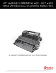
HP ® COLOR LASERJET ENTERPRISE CM4540
TONER CARTRIDGE REMANUFACTURING INSTRUCTIONS
HP COLOR LASERJET ENTERPRISE CM4540 TONER CARTRIDGE
www.uninetimaging.com
© 2012 UniNet Imaging Inc. All trademark names and artwork are property of their respective owners. Product brand names mentioned are intended to show compatibility only.
UniNet Imaging does not warrant downloaded information. Unauthorized sale, reproduction or distribution of this article is prohibited. For additional support, please contact [email protected]
HP CM4540 SERIES TONER CARTRIDGE REMANUFACTURING INSTRUCTIONS
REMANUFACTURING THE HP COLOR LASERJET
ENTERPRISE CM4540 SERIES TONER CARTRIDGES
By Mike Josiah and the Technical Staff at UniNet
The CM4540 series of multi function color laser printers are based on a 42 ppm black and color 600 x 600 DPI engine, 3600
DPI with RET (resolution enhancement technology). The 4540 cartridges are an all in one type cartridge that consists of the toner
supply, drum, and waste chamber. Like a few of the other newer high volume HP color laser printers, the cartridges in this series
are orientated so that the drum faces up not down when placed in the printer. Because of this machine layout, we will take a
moment and run through the printer theory before we get started.
The cartridge is basically a modified HP CP4525 cartridge. In fact, the CE260A works in both series, as does the waste collection
bottle. They all have a toner seal and a snap-on drum cover across the bottom to protect the drum.
These printers have a separate waste bottle to collect the waste toner from the ITB belt and use chips that’s need to be replaced
each cycle. The color cartridges and the high yield Black have a larger shoulder on the toner hopper.
www.uninetimaging.com
© 2012 UniNet Imaging Inc. All trademark names and artwork are property of their respective owners. Product brand names mentioned are intended to show compatibility only.
UniNet Imaging does not warrant downloaded information. Unauthorized sale, reproduction or distribution of this article is prohibited. For additional support, please contact [email protected]
HP CM4540 SERIES TONER CARTRIDGE REMANUFACTURING INSTRUCTIONS
The major difference between the CP4525 cartridges and the high yield cartridges in this series is the plastic housing (shoulder)
and the drum. The contact hub of the new CM4540 drum is larger with the inner hub that houses the drum axle pin stronger and
more recessed.
The older CP4525 drum hub design had a tendency to allow the drum axle pin to move out of the hub slightly when large runs
were printing causing print defects. This new design seems to be keeping the drum axle pin firmly in place.
PRINTERS BASED ON THE CM4540 ENGINE
HP Color LaserJet Enterprise CM4540 MFP
HP Color LaserJet Enterprise CM4540f MFP
HP Color LaserJet Enterprise CM4540fskm MFP
CARTRIDGES USED IN THESE MACHINES
CE260A (Black)
8,500 pages
CE264X (Black high yield)
17,000pages
CF031A (Cyan)
12,500 pages
CF033A (Magenta)
12,500 pages
CF032A (Yellow)
12,500 pages
CE265A (Toner collection unit)
$159.99 list*
$280.90 list*
$350.86 list*
$350.86 list*
$350.86 list*
$18.00 list*
*Pricing (in U.S. American Dollars) current as of September 2012.
www.uninetimaging.com
© 2012 UniNet Imaging Inc. All trademark names and artwork are property of their respective owners. Product brand names mentioned are intended to show compatibility only.
UniNet Imaging does not warrant downloaded information. Unauthorized sale, reproduction or distribution of this article is prohibited. For additional support, please contact [email protected]
HP CM4540 SERIES TONER CARTRIDGE REMANUFACTURING INSTRUCTIONS
HP-CP4520 COLOR PRINTING THEORY
The color toner cartridge printing process happens in a series of stages or steps. For the purpose of this article, we will call them
stages. Shown above is a basic layout of the cartridges and how they relate to one another and the printer. Note that while this
is still a single-pass system, the layout is completely different from any previous Canon/HP machines. The laser units are on the
bottom, the cartridges are at an angle, and the ITB is on top.
Shown is the complete image formation process.
www.uninetimaging.com
© 2012 UniNet Imaging Inc. All trademark names and artwork are property of their respective owners. Product brand names mentioned are intended to show compatibility only.
UniNet Imaging does not warrant downloaded information. Unauthorized sale, reproduction or distribution of this article is prohibited. For additional support, please contact [email protected]
HP CM4540 SERIES TONER CARTRIDGE REMANUFACTURING INSTRUCTIONS
In the first stage, light from the pre-exposure LED strikes the drum to remove any residual charges from the drum’s surface.
Then, the Primary Charge Roller (PCR) places a uniform negative DC voltage on the OPC drum surface. The amount of the
negative DC voltage placed on the drum is controlled by the printer’s intensity setting.
www.uninetimaging.com
© 2012 UniNet Imaging Inc. All trademark names and artwork are property of their respective owners. Product brand names mentioned are intended to show compatibility only.
UniNet Imaging does not warrant downloaded information. Unauthorized sale, reproduction or distribution of this article is prohibited. For additional support, please contact [email protected]
HP CM4540 SERIES TONER CARTRIDGE REMANUFACTURING INSTRUCTIONS
In the second stage, a dual laser beam is fired onto a rotating mirror (called the scanner). As the mirror rotates, the beams are
reflected into a set of focusing lenses. The beams then strike the drums surface, reducing the negative charge and leaving a
latent electrostatic image on the drum. The areas where the lasers did not strike the drum will retain the higher negative charge.
While some previous printers had one scanner unit with four lasers, these machines have two separate laser/scanner units:
one for Black and Cyan, and one for Magenta and Yellow. Dual lasers are used to allow faster print speeds.
www.uninetimaging.com
© 2012 UniNet Imaging Inc. All trademark names and artwork are property of their respective owners. Product brand names mentioned are intended to show compatibility only.
UniNet Imaging does not warrant downloaded information. Unauthorized sale, reproduction or distribution of this article is prohibited. For additional support, please contact [email protected]
HP CM4540 SERIES TONER CARTRIDGE REMANUFACTURING INSTRUCTIONS
The third or developing stage is where the toner is developed on the drum by the developing section (or supply chamber),
which contains the toner particles. The development stage is actually made up of two steps: toner charging and the actual
development. In the toner charging stage, the toner stirring blade turns inside the hopper. As it turns, friction causes a negative
potential to develop on the toner. In addition, a foam feed roller brings the toner to the developer roller and also places a
negative charge on the toner. These two charges help ensure a uniform charge on the toner.
Once the toner is properly charged, the toner will coat the developer roller. The toner is also held onto and attracted to the
developer roller by another negative DC bias voltage. This voltage is controlled by the printer’s intensity setting and causes either
more or less toner to be attracted by the developer roller. This in turn will either increase or decrease the print density. The amount
of toner on the developer roller is controlled by the doctor blade, which uses pressure to keep the amount of toner on the roller
constant.
www.uninetimaging.com
© 2012 UniNet Imaging Inc. All trademark names and artwork are property of their respective owners. Product brand names mentioned are intended to show compatibility only.
UniNet Imaging does not warrant downloaded information. Unauthorized sale, reproduction or distribution of this article is prohibited. For additional support, please contact [email protected]
HP CM4540 SERIES TONER CARTRIDGE REMANUFACTURING INSTRUCTIONS
As the laser-exposed areas of the OPC drum approach the developer roller, the toner particles are attracted to the drum’s surface
due to the opposite voltage potentials of the toner, and laser exposed areas of the OPC drum.
The fourth stage is the transfer stage. This is where there are some large differences from monochrome printers and also from
other color lasers. In the primary transfer stage the transfer roller which is located directly opposite each OPC drum, places a
positive DC bias charge on the back of the ITB or Image Transfer Belt. Each toner cartridge has a separate transfer charge roller.
The image is transferred from the drum directly to the ITB. This process is repeated for each color cartridge in the following order:
Yellow, Magenta, Cyan, and Black. At the same time, the paper is moving between the secondary transfer roller and the ITB.
As the ITB passes the secondary transfer roller, the positive charge is picked up, and draws the negatively charged toner off the
belt and onto the paper. Note that this entire process is upside down from most previous HP engines. The ITB and transfer rollers
are on top of the OPC drum, not underneath it..
www.uninetimaging.com
© 2012 UniNet Imaging Inc. All trademark names and artwork are property of their respective owners. Product brand names mentioned are intended to show compatibility only.
UniNet Imaging does not warrant downloaded information. Unauthorized sale, reproduction or distribution of this article is prohibited. For additional support, please contact [email protected]
HP CM4540 SERIES TONER CARTRIDGE REMANUFACTURING INSTRUCTIONS
The paper separates from the ITB belt as the belt turns back down to start the process again. The static charge on the back of
the paper is decreased with static charge eliminator. This helps stabilize the paper feed, and also prevents toner flares (spots)
under low temperature and low humidity conditions.
www.uninetimaging.com
© 2012 UniNet Imaging Inc. All trademark names and artwork are property of their respective owners. Product brand names mentioned are intended to show compatibility only.
UniNet Imaging does not warrant downloaded information. Unauthorized sale, reproduction or distribution of this article is prohibited. For additional support, please contact [email protected]
HP CM4540 SERIES TONER CARTRIDGE REMANUFACTURING INSTRUCTIONS
In the fifth stage, the image is then fused onto the paper by the fuser assembly. The fuser assembly is comprised of the upper
heating assembly and lower pressure roller. The lower pressure roller presses the page up into the upper heating assembly which
then melts the toner into the paper. This heating assembly consists of a flexible sleeve with a ceramic heating coil inside.
This type of fuser affords “instant on” fusing with little to no wait time, and low power consumption.
www.uninetimaging.com
© 2012 UniNet Imaging Inc. All trademark names and artwork are property of their respective owners. Product brand names mentioned are intended to show compatibility only.
UniNet Imaging does not warrant downloaded information. Unauthorized sale, reproduction or distribution of this article is prohibited. For additional support, please contact [email protected]
HP CM4540 SERIES TONER CARTRIDGE REMANUFACTURING INSTRUCTIONS
ITB CLEANING
The ITB is cleaned by the ITB cleaning blade.
The ITB wiper blade scrapes off the residual toner and an auger moves the toner to the toner collection box.
www.uninetimaging.com
© 2012 UniNet Imaging Inc. All trademark names and artwork are property of their respective owners. Product brand names mentioned are intended to show compatibility only.
UniNet Imaging does not warrant downloaded information. Unauthorized sale, reproduction or distribution of this article is prohibited. For additional support, please contact [email protected]
HP CM4540 SERIES TONER CARTRIDGE REMANUFACTURING INSTRUCTIONS
OPC DRUM CLEANING
The drum is cleaned after the image is transferred to the paper by the wiper blade. This part is fairly standard: the wiper blade
scrapes the toner off the drum, and the recovery blade guides it into the waste chamber.
www.uninetimaging.com
© 2012 UniNet Imaging Inc. All trademark names and artwork are property of their respective owners. Product brand names mentioned are intended to show compatibility only.
UniNet Imaging does not warrant downloaded information. Unauthorized sale, reproduction or distribution of this article is prohibited. For additional support, please contact [email protected]
HP CM4540 SERIES TONER CARTRIDGE REMANUFACTURING INSTRUCTIONS
These printers can print in full color or in black-only modes. To print in the black-only mode, the printer disengages the
developer rollers in the cyan, magenta, and yellow cartridges. This process also takes place with the primary transfer rollers and
the ITB belt.
www.uninetimaging.com
© 2012 UniNet Imaging Inc. All trademark names and artwork are property of their respective owners. Product brand names mentioned are intended to show compatibility only.
UniNet Imaging does not warrant downloaded information. Unauthorized sale, reproduction or distribution of this article is prohibited. For additional support, please contact [email protected]
HP CM4540 SERIES TONER CARTRIDGE REMANUFACTURING INSTRUCTIONS
PRINTER CALIBRATION
At the start of all this is the cartridge detection process, toner level detection, and then the calibration cycle. The printer will
calibrate whenever the printer is turned on (within 15 minutes), when a new toner cartridge is installed and after 48 hours of run
time. Calibration consists of a solid block and halftone of each color being printed to the ITB. As the printed areas get to the top
of the belt, a sensor will detect them, measure the density, and adjust the printer accordingly. All of the calibration time settings
are user controllable.
Taking test prints, cartridge troubleshooting, as well as minor printer troubleshooting will be covered at the end of this article.
REQUIRED TOOLS
1. Toner approved vacuum
2. A small screwdriver (common style)
3. A Phillips head screwdriver
4. Needle nose pliers
5. Spring hook
SUPPLIES REQUIRED
1. Toner for use in the HP CM4540
2. New replacement chip
3. New dedicated long life drum for use in the CM4540
4. New wiper blade
5. New toner feed roller (optional)
6. New PCR (optional)
7. New doctor blade (optional)
8. Drum cover
9. Lint-free cloths
10. Conductive grease
www.uninetimaging.com
© 2012 UniNet Imaging Inc. All trademark names and artwork are property of their respective owners. Product brand names mentioned are intended to show compatibility only.
UniNet Imaging does not warrant downloaded information. Unauthorized sale, reproduction or distribution of this article is prohibited. For additional support, please contact [email protected]
HP CM4540 SERIES TONER CARTRIDGE REMANUFACTURING INSTRUCTIONS
1. The pins in these cartridges are stepped. In other words the
outside is thicker than the inside. To remove the pins, you
must carefully shave the plastic away from the pins.
The procedure is described in the following steps:
First, remove the spring from the label side of the cartridge.
UN-CUT
UN-CUT
CUT
CUT
2. With a razor knife, carefully shave the plastic from the heads of the hinge pins on both sides of the cartridge.
www.uninetimaging.com
© 2012 UniNet Imaging Inc. All trademark names and artwork are property of their respective owners. Product brand names mentioned are intended to show compatibility only.
UniNet Imaging does not warrant downloaded information. Unauthorized sale, reproduction or distribution of this article is prohibited. For additional support, please contact [email protected]
HP CM4540 SERIES TONER CARTRIDGE REMANUFACTURING INSTRUCTIONS
3. On the label side only, drill a shallow hole on each side of the pin as shown.
4. Remove the pins with flush cutting wire cutters.
The smaller pin fits on the contact side of the cartridge, the long pin on the label or gear side.
www.uninetimaging.com
© 2012 UniNet Imaging Inc. All trademark names and artwork are property of their respective owners. Product brand names mentioned are intended to show compatibility only.
UniNet Imaging does not warrant downloaded information. Unauthorized sale, reproduction or distribution of this article is prohibited. For additional support, please contact [email protected]
HP CM4540 SERIES TONER CARTRIDGE REMANUFACTURING INSTRUCTIONS
5. On the gear side, press in on the plastic locking mechanism.
6. On the opposite side, lift up on the black lever.
Lift the two halves apart.
7. On the waste chamber, remove the two screws from the drum gear end cap.
Press in on the tab as shown and remove the end cap.
There is no need to remove the opposite side end cap.
www.uninetimaging.com
© 2012 UniNet Imaging Inc. All trademark names and artwork are property of their respective owners. Product brand names mentioned are intended to show compatibility only.
UniNet Imaging does not warrant downloaded information. Unauthorized sale, reproduction or distribution of this article is prohibited. For additional support, please contact [email protected]
HP CM4540 SERIES TONER CARTRIDGE REMANUFACTURING INSTRUCTIONS
8. Remove the drum.
9. Remove the PCR by lifting up on the black and white PCR
locking arms. Remove the PCR assembly.
10. To remove the wiper blade, the amber film assembly needs
to be removed. Slide a razor knife under the plastic mounting
bar as shown.
www.uninetimaging.com
© 2012 UniNet Imaging Inc. All trademark names and artwork are property of their respective owners. Product brand names mentioned are intended to show compatibility only.
UniNet Imaging does not warrant downloaded information. Unauthorized sale, reproduction or distribution of this article is prohibited. For additional support, please contact [email protected]
HP CM4540 SERIES TONER CARTRIDGE REMANUFACTURING INSTRUCTIONS
Remove the assembly.
11. Remove the two screws from the wiper blade. Slide the razor knife along the back edge of the blade to release it from the
glue. Remove the wiper blade. Clean out all the waste toner from the chamber. Try not to get any toner on the wiper blade seal if
possible.
www.uninetimaging.com
© 2012 UniNet Imaging Inc. All trademark names and artwork are property of their respective owners. Product brand names mentioned are intended to show compatibility only.
UniNet Imaging does not warrant downloaded information. Unauthorized sale, reproduction or distribution of this article is prohibited. For additional support, please contact [email protected]
HP CM4540 SERIES TONER CARTRIDGE REMANUFACTURING INSTRUCTIONS
12. Clean the felt seals on each end of the wiper blade. If the wiper blade glue has toner on it, clean it off with alcohol and a foam
swab. If it does not become sticky again, it needs to be removed and a good silicone caulk used to seal the blade off. GE 100%
Silicone and Phenoseal are two good brands for this.
13. Install the new wiper blade and two screws.
If you removed the wiper blade glue, seal the back edge of the blade with the silicone now.
www.uninetimaging.com
© 2012 UniNet Imaging Inc. All trademark names and artwork are property of their respective owners. Product brand names mentioned are intended to show compatibility only.
UniNet Imaging does not warrant downloaded information. Unauthorized sale, reproduction or distribution of this article is prohibited. For additional support, please contact [email protected]
HP CM4540 SERIES TONER CARTRIDGE REMANUFACTURING INSTRUCTIONS
14. The amber film assembly is held in place with double-sided
tape. If this is not sticking or a new wiper blade is being used,
replace the tape. Replace the film assembly.
15. Clean the PCR with your preferred cleaner and install in the cartridge with the PCR holders.
www.uninetimaging.com
© 2012 UniNet Imaging Inc. All trademark names and artwork are property of their respective owners. Product brand names mentioned are intended to show compatibility only.
UniNet Imaging does not warrant downloaded information. Unauthorized sale, reproduction or distribution of this article is prohibited. For additional support, please contact [email protected]
HP CM4540 SERIES TONER CARTRIDGE REMANUFACTURING INSTRUCTIONS
Make sure you lock the locking arms in place.
16. Install the drum, short-hub side onto the long drum ground
pin.
17. Install the end cap and two screws.
Place the waste chamber aside.
www.uninetimaging.com
© 2012 UniNet Imaging Inc. All trademark names and artwork are property of their respective owners. Product brand names mentioned are intended to show compatibility only.
UniNet Imaging does not warrant downloaded information. Unauthorized sale, reproduction or distribution of this article is prohibited. For additional support, please contact [email protected]
HP CM4540 SERIES TONER CARTRIDGE REMANUFACTURING INSTRUCTIONS
18. On the supply chamber, remove the screw from the gear
side end cap.
19. Press in on the tab and remove the end cap.
20. On the center gear press on the locking tab to release the
gear. Remove all the gears as shown except for the mixing
blade gear and the sealing strip gear. The mixing blade gear is
attached to the mixing blade inside the hopper and is very
difficult to re-attach properly.
www.uninetimaging.com
© 2012 UniNet Imaging Inc. All trademark names and artwork are property of their respective owners. Product brand names mentioned are intended to show compatibility only.
UniNet Imaging does not warrant downloaded information. Unauthorized sale, reproduction or distribution of this article is prohibited. For additional support, please contact [email protected]
HP CM4540 SERIES TONER CARTRIDGE REMANUFACTURING INSTRUCTIONS
21. Remove the two screws on the contact side.
Press in on the tab and remove the end cap.
22. Remove the three developer roller drive gears.
www.uninetimaging.com
© 2012 UniNet Imaging Inc. All trademark names and artwork are property of their respective owners. Product brand names mentioned are intended to show compatibility only.
UniNet Imaging does not warrant downloaded information. Unauthorized sale, reproduction or distribution of this article is prohibited. For additional support, please contact [email protected]
HP CM4540 SERIES TONER CARTRIDGE REMANUFACTURING INSTRUCTIONS
23. On the gear side inner end cap, remove the two screws
and end cap.
24. Remove the developer roller.
25. Remove the single screw and contact side inner end cap.
www.uninetimaging.com
© 2012 UniNet Imaging Inc. All trademark names and artwork are property of their respective owners. Product brand names mentioned are intended to show compatibility only.
UniNet Imaging does not warrant downloaded information. Unauthorized sale, reproduction or distribution of this article is prohibited. For additional support, please contact [email protected]
HP CM4540 SERIES TONER CARTRIDGE REMANUFACTURING INSTRUCTIONS
26. Remove the two screws from the doctor blade and start to lift the blade up.
There is glue on either rend of the blade.
As you lift the blade up, slice the glue away from the blade with the razor knife.
27. On the right side of the chamber lift up the felt developer
roller seal. Lift it from the front side and lay it over the back
28. Remove the white felt washers from both sides of the feed
roller.
www.uninetimaging.com
© 2012 UniNet Imaging Inc. All trademark names and artwork are property of their respective owners. Product brand names mentioned are intended to show compatibility only.
UniNet Imaging does not warrant downloaded information. Unauthorized sale, reproduction or distribution of this article is prohibited. For additional support, please contact [email protected]
HP CM4540 SERIES TONER CARTRIDGE REMANUFACTURING INSTRUCTIONS
29. Pry out the rubber feed roller bushing from the right side.
30. Remove the feed roller.
www.uninetimaging.com
© 2012 UniNet Imaging Inc. All trademark names and artwork are property of their respective owners. Product brand names mentioned are intended to show compatibility only.
UniNet Imaging does not warrant downloaded information. Unauthorized sale, reproduction or distribution of this article is prohibited. For additional support, please contact [email protected]
HP CM4540 SERIES TONER CARTRIDGE REMANUFACTURING INSTRUCTIONS
31. Clean out the remaining toner and fill with the correct color
of dedicated toner for use in CM4540.
32. When a seal is available, install the seal onto the seal rails.
Pull the release tape off one-inch at a time and press the seal
in place as you go.
33. Remove the seal port and slide the seal pull-tab through the slot. Install the seal port.
www.uninetimaging.com
© 2012 UniNet Imaging Inc. All trademark names and artwork are property of their respective owners. Product brand names mentioned are intended to show compatibility only.
UniNet Imaging does not warrant downloaded information. Unauthorized sale, reproduction or distribution of this article is prohibited. For additional support, please contact [email protected]
HP CM4540 SERIES TONER CARTRIDGE REMANUFACTURING INSTRUCTIONS
34. Install the feed roller and rubber bushing.
35. Install the feed roller felt washers.
36. Press the developer roller felt seal back in place. Make sure it fits under the retaining blade.
If needed, clean the adhesive with alcohol and a foam swab.
www.uninetimaging.com
© 2012 UniNet Imaging Inc. All trademark names and artwork are property of their respective owners. Product brand names mentioned are intended to show compatibility only.
UniNet Imaging does not warrant downloaded information. Unauthorized sale, reproduction or distribution of this article is prohibited. For additional support, please contact [email protected]
HP CM4540 SERIES TONER CARTRIDGE REMANUFACTURING INSTRUCTIONS
37. Use the appropriate shims to gap the blade and install the
doctor blade and two screws. Make sure the sticky seals on
either rend of the blade seal correctly. If the material is no
longer sticky clean it with alcohol or replace it with a small
amount of silicon.
38. Clean the contacts and replace the conductive grease on
the inner contact end cap. Install the inner contact end cap
and screw.
39. Install the cleaned developer roller. Do not use any
chemicals to clean this. A lint free cloth works fine.
40. Install the inner gear end cap and two screws.
www.uninetimaging.com
© 2012 UniNet Imaging Inc. All trademark names and artwork are property of their respective owners. Product brand names mentioned are intended to show compatibility only.
UniNet Imaging does not warrant downloaded information. Unauthorized sale, reproduction or distribution of this article is prohibited. For additional support, please contact [email protected]
HP CM4540 SERIES TONER CARTRIDGE REMANUFACTURING INSTRUCTIONS
41. Install the gears in the order shown. If you installed a seal,
slide the seal end through the take up gear and wrap the loose
tail tight on the roller.
42. Install the remaining gears in the order shown.
43. Install the outer gear end cap and screw.
www.uninetimaging.com
© 2012 UniNet Imaging Inc. All trademark names and artwork are property of their respective owners. Product brand names mentioned are intended to show compatibility only.
UniNet Imaging does not warrant downloaded information. Unauthorized sale, reproduction or distribution of this article is prohibited. For additional support, please contact [email protected]
HP CM4540 SERIES TONER CARTRIDGE REMANUFACTURING INSTRUCTIONS
44. Place the triple gear on the developer roller shaft and fit into the spring assembly on the end cap.
Install the opposite side end cap and install the screw.
45. Place the two halves together contact side first. On the gear side, press the lever in place.
On the contact side snap the lock up into the end cap.
www.uninetimaging.com
© 2012 UniNet Imaging Inc. All trademark names and artwork are property of their respective owners. Product brand names mentioned are intended to show compatibility only.
UniNet Imaging does not warrant downloaded information. Unauthorized sale, reproduction or distribution of this article is prohibited. For additional support, please contact [email protected]
HP CM4540 SERIES TONER CARTRIDGE REMANUFACTURING INSTRUCTIONS
46. Install the two pins.
47. Install the spring.
Large pin goes to the label or gear side of the cartridge.
48. Remove the chip by cutting the plastic off the edges of
both side of the chip.
49. Remove and replace the chip. If the new replacement chip
is loose in the slot. Close off the top edges with small amounts
of hot glue.
www.uninetimaging.com
© 2012 UniNet Imaging Inc. All trademark names and artwork are property of their respective owners. Product brand names mentioned are intended to show compatibility only.
UniNet Imaging does not warrant downloaded information. Unauthorized sale, reproduction or distribution of this article is prohibited. For additional support, please contact [email protected]
HP CM4540 SERIES TONER CARTRIDGE REMANUFACTURING INSTRUCTIONS
50. Install the drum cover on to the cartridge.
TAKING TEST PRINTS
Configuration Page:
1. Scroll to and touch the Administration button
2. Open the following menus: Reports / Configuration/Status Pages / Configuration Page
3. Touch the Print button
4. Print Quality TEST PAGES
5. Scroll to and touch the Administration button
6. Scroll to and touch the Troubleshooting button
7. Touch the Print Quality Pages button
8. Touch the PQ Troubleshooting Pages button
9. Touch the Print button
10. Follow the instructions on the pages that print out.
Diagnostics Page:
1. Scroll to and touch the Administration button
2. Scroll to and touch the Troubleshooting button
3. Touch the Print Quality Pages button
4. Touch the Diagnostics Page button
5. Touch the Print button
6. Follow the instructions on the pages that print out.
Cleaning Page:
1. From the Home screen: touch the device Maintenance Button
2. Open the following menus: Calibrate/Cleaning / Cleaning Page
3. Touch the Print button
4. The cleaning process will take several minutes
www.uninetimaging.com
© 2012 UniNet Imaging Inc. All trademark names and artwork are property of their respective owners. Product brand names mentioned are intended to show compatibility only.
UniNet Imaging does not warrant downloaded information. Unauthorized sale, reproduction or distribution of this article is prohibited. For additional support, please contact [email protected]
HP CM4540 SERIES TONER CARTRIDGE REMANUFACTURING INSTRUCTIONS
REPETITIVE DEFECT CHART
NOTE: The HP service manual is less than helpful on repetitive defects with their current chart. The first description column shows
HP’s description. We have added what we know in the second description column, which is based on the older HP CP4025
service manual and our tests.
Distance
HP Description
Our Description
27.0 mm
Print cartridge
Primary charge roller
32.0 mm
Print cartridge
Developer roller sleeve
44.0 mm
Transfer unit
Secondary transfer unit
48.0 mm
Print cartridge
51.0 mm
Transfer roller
55.0 mm
Print engine
63.0 mm
Transfer unit
Secondary transfer backing roller
76.0 mm
Print cartridge
OPC drum
76.0 mm
Fuser
Fuser sleeve
80.0 mm
Fuser
Fuser pressure roller
96.0 mm
Print engine
101.0 mm
Print engine
Primary transfer roller
www.uninetimaging.com
© 2012 UniNet Imaging Inc. All trademark names and artwork are property of their respective owners. Product brand names mentioned are intended to show compatibility only.
UniNet Imaging does not warrant downloaded information. Unauthorized sale, reproduction or distribution of this article is prohibited. For additional support, please contact [email protected]