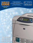
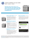
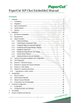
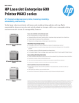
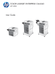
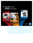
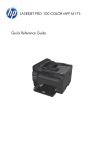
1
SERVICE
EDGE
The Laser Printer Tech Quarterly
from Liberty Parts Team
Summer 2014
THIS ISSUE:
• P4015 Transfer Block Replacement
• Replacing the M600 Fuser Drive
• P3005 Formatter and Ribbon Cables
•Three new fuser rebuilds
•CARTOON: Parts in Space
SE RV ICE E DGE, SU M M ER 2 0 1 4
PRODUCTS NEWS
M600 Feed Asm Change
THE NEW PAPER FEED ASM (FOREGROUND) HAS
NO BLACK GUIDE AND MAY REDUCE JAMS.
HP has modified the paper feed assembly for the LJ M60x
printer series, removing the black plastic guide above the rollers. Apparently, the guide was causing more paper jams than it
was preventing.
If you are getting paper jams in the paper feed area, you
should upgrade to the improved version. The part number is
RM1-8411-N.
Fuser Drive Asm for the
M600 Series Available
There is now
a cure for grinding noise in the
LaserJet M600
series. The
noise is caused
by a worn-out
fuser drive
gear assembly,
which LPT now
stocks.
The fuser drive gear asm is a metal plate with six
gears and is similar to the P4014/P4015/P4515
fuser drive gear asm. The part number is RC22432-M601.
Like the swing plate in the 4200 series, the fuser
drive asm turns the gears in the fuser. Unlike the
swing plate, this asm itself is not activated by a
main drive assembly but by a fuser motor. Also, it
has no swing arm.
LPT Introduces
Three New Rebuilds
Liberty Parts Team introduced three new fuser
rebuilds this summer. The first two are similar but
not interchangeable.
CE246A is the fuser for the CP4025, CP4525
and CM4540. These printers use fuse technology to reset the fuser life count. In this case, the
fuse in question doesn't open until 100 pages
have been printed. This is useful for troubleshooting print problems. Bear in mind that the fuser
count will not go to 100% life until 100 pages
have been printed. This is true for new as well as
our remanufactured fusers.
CE484A is for the CP3525, CM3530, M551
and M575. For these printers, resetting the page
count is done through the printer menu.
SERVICE EDGE is the quarterly laser printer tech
bulletin of Liberty Parts Team.
Editor-in-Chief: David K. Reinke
Editor:
Robert Reinke
Tech Writer:
Dennis Kosterman
©2014 Liberty Parts Team, Inc.
2
RM1-8808 is for the M421 and M425. It is
similar to the P2035/P2055 fuser.
As always, every rebuilt fuser is remanufactured, tested and inspected in the USA.
SERVICE ED GE, S UMMER 2014
PARTS IN SPACE!
with arzno wrk
3
SE RV ICE E DGE, SU M M ER 2 0 1 4
PRINTER REPAIR ARTICLE
Fuser Drive Asm Replacement
for the LJ M600 Series
The HP LaserJet M600 family is the replacement for the
P4014/P4015/P4515. As is the case with most high-speed
laser printers, there a tendency for the gears in the fuser drive
asm to wear out, resulting in grinding noise.
The fuser drive asm for the M600 series is different from the
P4015 version (the gears are now helical), and the procedure
for replacing it is also slightly different. A step-by-step procedure follows (unless stated otherwise, left-right designations
are as viewed from the front of the printer).
1 Remove the toner cartridge and paper cassette. Make sure to
4
put the toner cartridge in a dark place or cover it – prolonged
exposure to ambient light can damage the drum.
2 Remove top accessories or top-accessory cover. Remove any
output accessories (stacker, mailbox, etc.). If there are none, remove the top-accessory cover (toward the back of the printer,
on top) by simply lifting it up. There are retaining tabs on each
side, but they will release themselves as you pull up on the cover.
3 Remove the duplexer or duplex accessory cover. Simply pull
the duplexer or the cover out of the printer (from the back) to
remove it.
4 Remove the tray 2 extension door (in back of printer). Carefully flex the door to release the hinge pin near the power cord
side of the printer. Then rotate the door to the horizontal position and pull up on the remaining hinge pin to release the door.
5 Remove the rear output bin. Open the bin and squeeze the
right hinge pin (on your left if you are behind the printer) out of
its mounting hole. Then rotate the bin away from the printer to
release the other hinge pin.
6 Remove the fuser. Squeeze the blue fuser-release tabs (one
on each side) and pull the fuser straight back and out of the
printer. When re-installing the fuser, make sure to push it in until
these tabs snap into place.
7 Remove the formatter. First remove the plastic formatter cover (right side of the printer, toward the back) by simply grasping it and sliding it straight back. To remove the metal formatter
cage, remove the two screws, then use the finger holes on the
side to grasp it and slide it straight back. This will require some
force, as you are also unplugging a connector. When reinstalling the board/cage, you may want to open the metal door on
the side of the cage so that you can visually verify correct seating of this connector.
8 Remove the top cover. Open the print-cartridge door and
the front cover. Use needle-nose pliers to release the print-car-
SERVICE ED GE, S UMMER 2014
tridge drive arm from the right side of the cover, and then push
the arm down into the printer (remember to re-attach this arm
when re-installing the cover). Remove four screws, one in each
of the four corners of the cover. Now partially close the printcartridge door, release two tabs (Fig. A), and lift the cover off
the printer. Take care to properly reseat these two tabs when reinstalling the cover. Also note that the accessory pin (in the leftrear corner of the cover) is not captive; take care not to lose it.
9 Remove the right-side cover. Release two tabs – one at the upper rear corner, and one along the top edge, directly above the
fan vent. Then slightly flex the cover to release the front edge,
rotate the top edge away from the printer, and lift up to remove
it.
10 Remove the left-side cover. Open the front cover and gently
flex the retainers to separate them from the tray 1 arms so that
you can open the cover all the way (this is to provide clearance
for the left cover). Now release two tabs (one along the top
edge of the left cover, and one along the front edge), rotate the
top of the cover away from the printer, and lift up to remove it.
11 Remove the power supply PCA guide (right side of printer,
toward the back). Remove one screw, release the retaining tab,
and slide the guide toward the rear of the printer to remove it
(Fig. B).
12 Remove the power supply. On the right side of the printer,
remove four screws and one grounding screw (Fig. B). Then unplug seven cables from the DC Controller, and one free cable
to the right (Fig. C). Feed these cables through the hole in the
chassis into the paper tray cavity below the power supply. On
the left side of the printer, remove two screws to remove the fancover plate (below the fan). This gives you access to three cables. Unplug them, and remove four screws which correspond
to four screws on the other side (Fig. B). Now grasp the power
supply from behind, lift it slightly, and slide it out the back of the
printer. NOTE: When removing and re-installing the power supply, take care not to dislodge the small rubber belts and plastic
rollers on the feed-guide assembly (mounted to the top of the
power supply).
13 Remove the RW crossmember plate: This is a metal piece
that attaches to the rear edge of the metal plate that supports
the laser/scanner. To remove it, it is necessary to remove four
screws. Two of these are easily accessed from the rear (Fig. D).
The other two (Fig. E) are accessed from the bottom by inserting one’s arms through the paper tray cavity.
14 Remove the fuser drive assembly. This is attached to the inner
surface of the right wall of the printer chassis by four screws, one
in each corner. To access the lower front screw, you will need
to remove a gear (Fig. F). This will require first removing a small
c-clip – take care not to lose it. Then remove the four screws and
pull the drive assembly away from the chassis, taking care not to
let any of the non-captive gears fall off.
15 Reverse the above steps to re-assemble the printer.
5
SE RV ICE E DGE, SU M M ER 2 0 1 4
TECH NOTE
Careful with
Ribbon Cables!
Apparent Formatter
Malfunctions Caused By
Bent Cable Teeth
A common P3005/M3025/35
issue that can happen with other
printers too
You buy and install a
new formatter for a
LaserJet P3005 and immediately experience
one of the following
problems.
Looping initialization without
reaching "ready"
• Blank display
• Stuck display (HP logo or
initializing screen)
You assume it is the new formatter and send it back. However, the
vendor tests it and finds no problem.
The culprit is the ribbon cable
from the ECU to the formatter, which,
like most ribbon cables, cannot bear
rough handling. Shoved into place
carelessly, the metal teeth can get
bent out of place, causing malfunction. In the case of the P3005, the
Engine Controller Unit (ECU) will
probably need replacing.
When plugging in ribbon cables,
just keep in mind that the teeth are
delicate. A good way to proceed is
to insert a corner and slide the rest
into place.
The ribbon cable issue is particularly common with the P3005,
M3025 and M3035. But be careful
with ribbon cables in all printers.
•
THE DELICATE P3005 RIBBON CABLE
6
LPT
SERVICE ED GE, S UMMER 2014
PRINTER TECH ARTICLE
Removing the
Transfer Block from
the P4015
The transfer block is the plastic core of the LaserJet P4xxx, the
4200/50 series, and the M60x. This
frequently replaced part contains
three things that can break or malfunction.
(1) the clips for mounting the
transfer roller;
(2) the high voltage contact
springs (these make the electrical
connections between the power
supply and the toner cartridge);
(3) the paper feed, registration,
and paper width sensors.
If any of these things break (and
item #1, in particular, often does
break), you will need to replace the
whole assembly. To replace it is a
long job, since almost total disassembly is required. No replacement
instructions exist for the transfer
block in the service manuals, except
for the 4200/4300 manual, the only
one to mention it.
To make the job as quick as possible, we've prepared the following
instructions, which are tailored for
the P4014, P4015, P4515. These instructions will be useful for the other
models provided they are used in
conjunction with the appropriate
service manual in order to navigate
the differences.
1 Remove the toner cartridge and
paper cassette. Make sure to put
the toner cartridge in a dark place
or cover it – prolonged exposure to
ambient light can damage the drum.
2 Remove top accessories or topaccessory cover. Remove any output
accessories (stacker, mailbox, etc.).
If there are none, remove the topaccessory cover (toward the back of
7
SE RV ICE E DGE, SU M M ER 2 0 1 4
8
the printer, on top) by simply lifting it
up (Fig. 1). There are retaining tabs
on each side, but they will release
themselves as you pull up on the
cover.
3 Remove the duplexer or duplex
accessory cover. Simply pull the duplexer or the cover out of the printer
(from the back) to remove it.
4 Remove the tray 2 extension door
(in back of printer). Carefully flex the
door to release the hinge pin near
the power cord side of the printer.
Then rotate the door to the horizontal position and pull up on the
remaining hinge pin to release the
door (Fig. 2).
5 Remove the rear output bin. Open
the bin and squeeze the right hinge
pin (on your left if you are behind the
printer) out of its mounting hole (Fig.
3). Then rotate the bin away from
the printer to release the other hinge
pin.
6 Remove the fuser. Squeeze the
blue fuser-release tabs (one on each
side) and pull the fuser straight back
and out of the printer (Fig. 4). When
re-installing the fuser, make sure to
push it in until these tabs snap into
place.
7 Remove the formatter. First remove the plastic formatter cover
(right side of the printer, toward
the back) by simply grasping it and
sliding it straight back (Fig. 5). To
remove the metal formatter cage, remove two screws (Fig. 6), then use
the finger holes on the side to grasp
it and slide it straight back. This will
require some force, as you are also
unplugging a connector. When reinstalling the board/cage, you may
want to open the metal door on the
side of the cage so that you can visually verify correct seating of this connector.
8 Remove the top cover. Open the
print-cartridge door and the front
cover. Use needle-nose pliers to release the print-cartridge drive arm
SERVICE ED GE, S UMMER 2014
from the right side of the cover (Fig. 7), and then push the arm
down into the printer (remember to re-attach this arm when reinstalling the cover). Remove four screws, one in each of the
four corners of the cover (A in Fig. 8). Now partially close the
print-cartridge door, release two tabs (B in Fig. 8), and lift the
cover off the printer. Take care to properly reseat these two tabs
when re-installing the cover. Also note that the accessory pin
(in the left-rear corner of the cover) is not captive; take care not
to lose it.
9 Remove the right-side cover. Release three tabs – one along
the top edge, directly above the fan vent; one at the upper rear
corner (Fig. 9), and one at the front of the formatter cavity. Then
slightly flex the cover to release the front edge (Fig. 10), rotate
the top edge away from the printer, and lift up to remove it.
When re-installing the cover, make sure that the plastic power switch (on the cover) couples properly to the metal power
switch rod (in the printer) (Fig. 11).
10 Remove the left-side cover. Open the front cover and gently
flex the retainers to separate them from the tray 1 arms so that
you can open the cover all the way (this is to provide clearance
for the left cover). Now release two tabs (one along the top
edge of the left cover, and one along the front edge), rotate the
top of the cover away from the printer, and lift up to remove it.
11 Remove the dc controller PCA. Unplug all cables and remove them from their cable guides (Fig. 12). Note that many
of these cables have release tabs – do not try to unplug these
without releasing the tabs. Remove the formatter-connector
ground clip (the thin wire covering the small formatter connector PCA), then remove two screws to free this PCA (Fig. 13),
and finally, free the attached flat flexible cable from its retainer.
Then remove two screws from the dc controller PCA itself (Fig.
12), release one tab (lower right corner), and remove the PCA,
along with the formatter-connector PCA (they are hard-wired
to each other).
12 Remove the power supply PCA guide (right side of printer,
toward the back). Remove one or two screws (A in Fig. 14) and
release the retaining tab (B in Fig. 14), and slide the guide toward the rear of the printer to remove it.
13 Remove the power supply. On the right side of the printer,
remove four screws and one grounding screw (C in Fig. 14).
Feed the power supply cables (these will already have been
unplugged from the dc controller in the previous step) through
the hole in the chassis into the paper tray cavity below the power supply. Unhook the power-switch rod from the chassis, and
then pull down to remove it from the power supply (note that
the rod attaches to the power supply inside the paper tray cavity (Fig. 15) – observe this before removing it so you will know
where to re-attach it later). On the left side of the printer, remove
two screws to remove the fan-cover plate (below the fan) (A in
Fig. 16). This gives you access to three cables (Fig. 17). Unplug
them, and remove four screws (B in Fig. 16) which correspond
9
SE RV ICE E DGE, SU M M ER 2 0 1 4
10
to four screws on the other side (Fig. 14). Now grasp the power
supply from behind, lift it slightly, and slide it out the back of the
printer (Fig. 18). NOTE: When removing and re-installing the
power supply, take care not to dislodge the small rubber belts
and plastic rollers on the feed-guide assembly (mounted to the
top of the power supply).
14 Remove the rear-upper cover. Release one tab (Fig. 19), and
then rotate the cover away from the printer to remove it. When
re-installing, make sure to seat the hooks on the far end of the
cover before snapping the tab back in.
15 Remove the paper-delivery assembly. First remove the guide
by releasing two tabs at the top (Fig. 20) and then pushing up.
Use a pick or a small flat-blade screwdriver to release the locking
pin at the tip of the shaft lock, and then rotate the lock counterclockwise until you can pull it out (Figs. 21, 22). Then lift the gear
end of the paper-delivery assembly (taking care to disengage
the sensor cable from its slot) and slide the assembly toward the
formatter side of the printer to remove it. Be careful not to dislodge the sensor when removing or re-installing this assembly.
16 Remove the right-front cover. Open the front cover/tray 1
door, and remove the envelope feeder connector cover (Fig.
23). Then remove two screws in front (Fig. 23) and one on the
right side (Fig. 24), at the bottom, and pull the cover off.
17 Remove the tray 1 paper-pickup assembly. First disengage
tray 1 from the tray 1 cover (Fig. 25; this may have already been
done in step 10), then slide the cover to the right to remove it.
The tray 1 arms will have a tendency to spring away from the tray,
but this is no more than an annoyance, and can be minimized in
any case by keeping tray 1 folded up (as in Fig. 26) as much as
possible. Remove eight screws (Fig. 27), rotate the left side of
the assembly away from the front of the printer, and slide it to the
left to remove it. Take care to thread the cables through the holes
on the right (Fig. 28), and note cable routing (for re-installation).
18 Remove fans FN102 and FN103 (Fig. 29): For each fan, release the cable from the retainer on the fan duct, release one retaining tab (at the top for the left fan, at the bottom for the right
fan), and pull the fan straight out. When re-installing, make sure
airflow is into the printer (there is an arrow on the fan indicating
airflow direction).
19 Remove the pickup motor (B in Fig. 30) and the drum motor (A in Fig. 30): For both, disconnect the wire-harness, remove
three screws, and then pull the motor toward you to remove it
(you may have to rotate the motor to the right first to release a
retaining tab on the back of it).
20 Remove the two fan ducts: First, separate any remaining wire
harnesses from the two ducts. Then remove one screw from the
left duct (Fig. 31), and remove the ducts (the right one is secured
by retaining tabs, and can be removed by squeezing and wiggling it).
21 Remove the drum-drive assembly: Remove three screws (Fig.
32) and carefully remove the drum-drive assembly. Note that the
SERVICE ED GE, S UMMER 2014
large gear and spring are loose (Fig. 33). Make sure to properly
position them when re-installing the assembly. Also remove the
cam that is attached to the drum-drive disengaging arm (Figs.
34, 35), noting proper orientation for re-installment.
22 Remove the pickup-drive assembly: First, carefully remove
the e-clip, spring arm clip and associated springs, and shaft
collar (Fig. 36). Note the orientation of these parts (for later reassembly), because they may all come off at once when the eclip is removed. Now you can push the drive shaft through the
assembly into the tray 2 cavity to remove it (Fig. 37). Note that
an internal gear will come off the shaft and be loose inside the
drive assembly (Fig. 38). Take care not to lose this gear. (When
re-assembling, it may help to thread a pick or small screwdriver
through the hole in this gear to hold it in position while re-inserting the drive shaft.) Next, release one tab to remove the
black plastic guide (Fig. 39); also remove the wire guide on the
right side of the assembly (Fig. 40). Finally, remove six screws
(Fig. 40), reach inside the tray 2 cavity to push the feed roller up
into its raised position, and remove the pickup-drive assembly.
23 Remove the tray 1 drive assembly: Remove the plastic wire
guide, then remove two screws (Fig. 41) to remove this drive
assembly.
24 Remove the left lower cassette guide: Fig. 42 shows the
guide “from the inside” (looking in through the rear of the
printer). To remove it, remove two screws (Fig. 43) and slide
the guide toward the rear of the printer.
25 Remove the transfer block assembly: The basic idea is to
remove the left wall of the printer chassis. In our photos, we
have unscrewed the transfer block from the right wall, and then
removed the left wall with the transfer block still attached. It is
also possible to remove the left wall by itself, and then unscrew
the transfer block from the right wall. Either way, we are removing the same screws: on the right side, four screws (Fig. 44;
these attach the transfer block to the wall); on the left side, thirteen screws (Fig. 45). Of the left-side screws, five screw into the
laser/scanner shelf (A), two into the paper pickup/feed roller
shelf (B), three into the bottom of the printer chassis (C), and
finally, three into the transfer block (D; these can be temporarily
left in if you are removing the wall with the block still attached).
Figures 46 and 47 show the wall/block detached from the
printer.
NOTE: In this procedure, we have removed the transfer
block with the feed-roller assembly, registration assembly, and
transfer roller still attached to it. These three items will have to
be removed from the old block and attached to the new one.
We recommend doing this while the transfer block is removed
from the printer, but they can also be removed earlier (and reinstalled later).
LPT
11
Prsrt Std
U.S. Postage
PAID
Permit #168
Madison, WI
LIBERTY PARTS TEAM INC.
3517 W. BELTLINE HWY.
MADISON, WI 53713
888-444-8778
WWW.LBRTY.COM
LIBERTY PARTS TEAM OEM LJ PARTS SPECIALS
M601/M602/M603 500-sheet feeder
(CE998-67901-N)
New OEM: $239.00
M601/M602/M603 Maintenance Kit
(CF064A-N)
New OEM: $339.00
4250/4240/4350 Fuser
(RM1-1082-N)
New OEM: $189.00
CLJ 4600/4610/4650 Transfer Kit
(RG5-7455-N )
New OEM: $199.00
CLJ 4700/CP4005 Fuser
(RM1-3131-N)
New OEM: $259.00
These prices are valid thru September 30, 2014, while
quantities last.
CALL 888-444-8778