1
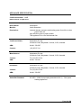
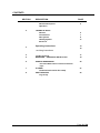
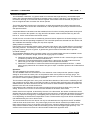
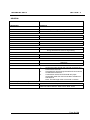
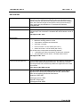
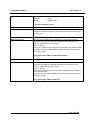
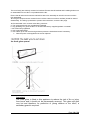
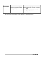
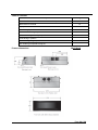
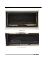
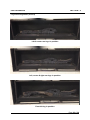
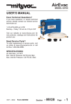
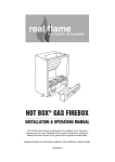
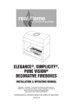
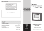
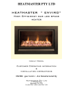
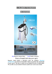
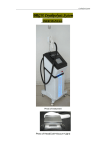
Seamless Customer Operation, Installation and Servicing Information Page 1 of 24 APPLIANCE SPECIFICATION Certificate Number: 8107 Date of Issue: 5 Sept 2014 Brand Name: Heatmaster Model/s: Inbuilt Seamless Description: Induced draught, luminous and heating power flue effect, mains power 240V AC High efficiency gas log space heater This appliance is for use with Natural Gas. Certificate Holder: Heatmaster Pty Ltd. 2/9 Nicole Close, Bayswater, Victoria, 3153, Australia ABN: 64-641-709-587 Contact: (03) 97617134 Manufacturer: Heatmaster Pty Ltd. 2/9 Nicole Close, Bayswater, Victoria, 3153, Australia Contact: Tel. (03) 97617134 ABN: 64-641-709-587 Distributor: Heatmaster Pty Ltd. 2/9 Nicole Close, Bayswater, Victoria, 3153, Australia Contact: Tel. (03) 97617134 ABN: 64-641-709-587 Australian Standard: AS 4553 – 2008 (incorporating amendment No 1) “Gas space heating appliances” Page 2 of 24 CONTENTS SECTION 1 2 3 DESCRIPTION PAGE PRODUCT OVERVIEW General Description Operation 4 TECHNICAL DATA General Construction Gas System Heating System Electrical 5 7 9 11 Operating Instructions 13 15 servicing instructions 4 5 Trouble shooting MARKINGS – APPLIANCE DATA PLATE 6 FIREBOX DIMENSIONS Rear View Balanced flue with 58 and 65mm Ø. 7 FLUEING Horizontal and vertical flue setup PHOTOGRAPHS Log set up 17 19 20 Pipes 8 21 22 Page 3 of 24 PRODUCT OVERVIEW SECTION 1 General Description The Heatmaster “Seamless” Log space heater is an induced draft, high efficiency, fan assisted space heater with a Remote Manual/ Automatic thermostat control, using a 2 step High- Low gas setting. Low is front burner and high is front and rear burners together. If decorative mode is selected, only the front burner will ignite and the convection fan will not operate. The heater gas safety functions are controlled by an AGA approved electronic flame supervision and ignition controller. This controls the combustion fan, and fan operation is proven by a Cleveland Control duel pressure switch. A separate Millennium branded controller handles all other functions including temperature sensing and control of convection fan speeds Low, High and Off if decorative mode is selected with only the front burner on. It also communicates with the RF remote. As well, the two convection fans are enabled by a thermal sensor adjacent to the heat exchanger, once the firebox has reached operating temperature. The actual fan speeds are selected from the remote and also modulate automatically in steps (Hi-Low) when required. Safety features included are: Flame failure and overheating safety system, automatic shut down if gas or power failure occurs and fan start-stop protection. On startup the combustion fan runs at a higher speed than normal to automatically purge any unburnt gas prior to ignition. A glass dress guard is fitted to the heater door to prevent accidental mishaps. The Heatmaster Seamless Gas Log space Heater is a room sealed heater that can be installed in three configurations. The maximum length of flue and air supply pipe is 12 meters. a) Fitted with two pipes vertical. A 60mm pipe to supply external air and a 50mm flue pipe to expel combustion products via a balanced flue terminal b) Fitted with a horizontal balanced flue configuration. A 60mm pipe to supply external air and a 50mm flue pipe to expel combustion products via a balanced flue terminal. c) Fitted with a combination of vertical and horizontal twin pipes suspended under floor. A 60mm pipe to supply external air and a 50mm flue pipe to expel combustion products via a balanced flue terminal Operation: The unit is started by the remote control. The SIT 590DBC starts the combustion fan. The millennium control ramps the fan speed to a higher setting for 30 seconds to ensure pull in of the pressure switch and to perform a thorough purge. The pressure switch proves the combustion air and enables the 579 to proceed to start-up. The combustion fan reverts to a lower operating speed for quietness. The front burner will ignite first in every case, and the flame detection of this burner is verified by the SIT 579 in approx 5 seconds. After 40 seconds from start up, and only after the front burner has ignited and satisfied the SIT 579 that it has flame, will the second burner and thermostatic operation be enabled. An interlock in the SIT 579 control ensures this. If decorative mode is selected, the unit cannot progress to the second burner stage or any room fan setting. IE there is no room fan or second burner available in decorative flame mode. If/when extra heat is required, as decided by the user or the thermostat, the remote control/main control will allow the second solenoid valve to supply gas to the rear burner, provided the decorative (front burner) is burning. This burner will ignite by cross-lighting from the front burner. Only the rear burner modulates on-off depending on thermostat for temperature control. The decorative only burner will not modulate OFF until switched off by the user or built in timer. The second solenoid for the rear burner can only be activated when the signal from the SIT 5479DBC confirms flame at the front burner. The power supply for the rear burner solenoid is provided from the flame signal of the SIT 579, so the power to the rear burner cannot be applied from any other source. This setup ensures absolute safety in that the rear heating burner cannot be supplied gas spuriously. The solenoid valve for the second burner is also a tandem double block approved valve. Page 4 of 24 TECHNICAL DATA SECTION 2 GENERAL BRAND NAME MODEL Heatmaster BURNERS Seamless Heatmaster, Inspiration type Rectangular Bar Burner, COMBINATION CONTROL SIT , double block , 840 IGNITION MODULE SIT, Electronic , 579DBC BURNER CONTROLLER SIT , double block , 840 Dungs double block valve for high setting. REGULATOR SIT , double block , 840 LOG SET Everburn, Ceramic Compressed Kaowool , Heatmaster Seamless FLUEING OPTIONS 1. 2. 3. Vertical twin pipe through the roof and connected to a balanced flue terminal. Horizontal twin pipe through the wall and connected to a balanced flue terminal Combination vertical and horizontal twin pipes suspended under floor and connected to a balanced flue terminal Note: The flue length must not exceed 12 meters. OPTIONS (Test Laboratory Assessed) Must be installed on a fireproof base. The following clearances from combustible materials must be observed: Above 300mm. Sides 12mm. Rear 10mm Page 5 of 24 TECHNICAL DATA SECTION 2 GENERAL Gas Type: Natural Gas @ 0.88kPa Test Point Pressure Burner Injector Size (mm) N.G.C. (MJ/h) Minimum. Front burner 1.95 18 Maximum. Both burners 1.95 36 Dimensions / Weight: Model Heatmaster Seamless Inbuilt Width (mm) 1295 Depth (mm) 495 Height (mm) 465 Weight (kg) 85kg Star Rating Model Heatmaster Seamless 4.0/4.2 Stars (Flue dependent) The test point pressure is set with ‘both burners’ on maximum. BURNERS are ON – OFF only Page 6 of 24 TECHNICAL DATA SECTION 2 CONSTRUCTION General The Heatmaster Seamless Gas Log Heater comprises of a metal fire box structure and a Heat Exchanger located within an outer casing, which has a transparent ceramic glass front door. The heat exchanger includes a primary heat exchanger (firebox) subject to gas heating, a secondary heat-exchanger made of tubular members heading from the firebox and connecting to the inlet header of the manifold flue fan box. The secondary heat exchanger is made of corrugated flexible stainless steel tubes, which are connected at their other end to the combustion fan, so as to extract and expel the combustion products from within the firebox, the tubular members and the manifold box. The combustion products are expelled to the atmosphere by the combustion fan through a flexible aluminium flue system of 50mm diameter to a balanced terminal. Two convection room fans are positioned at the bottom of the fire box structure so as to draw cool air from the room through an opening at the lower end of the firebox fascia this air is heated by passing through the outer surfaces of the primary and secondary heat exchanger’s and finally expelled into the space being heated. The double convection fans are so situated, that it provides a cooling effect on the working components, such as combustion fan and adjacent electronic controls. The cooling effect is not necessary in decorative mode and the convection fans do not operate. The firebox is made of 3 pieces of 1.2mm thick Aluminized steel sheet, press folded and assembled and joined by TIG/MIG welded construction. The burners are fastened to the firebox assembly by two locating slots and 3.2 mm screws located at each ends of the burner tray. The front of the firebox is sealed with the door frame made of one piece of 2.5 mm thick mild steel sheet, pressed and folded. The door is sealed with a 19mm Ø. fiber glass rope and a fiber glass tape around the 5.0mm Ceramic glass edges. Four M6 x 35mm screws mount the door assembly on the firebox and maintain it in place firmly and gas tight. The external outer panels and fascia are made of pressed and folded 1mm thick Aluminized Steel. The external front trim is aluminum. Refer Drawings HMR-716-206,213,215,216,217,218,227,228,229 & 230 Primary Guard GLASS The primary guard is 5.0mm Ceramic glass approximately the size of the door assembly. It is hung on supporting brackets at each end, is approximately 20mm from the door glass and is removable for cleaning etc. It allows convection between the glass and the door for cooling of the guard. The edge gaps preclude the temperature test cone as per AS4553 Refer Drawings HMR-716-201,262 & 263 Page 7 of 24 TECHNICAL DATA SECTION 2 Primary Air The primary Air for combustion is drawn into the firebox through a 60 mm pipe of 1.6mm mild steel attached to the firebox back side air inlet hole opening of 60 mm diameter Refer Drawing HMR-716-212 Combustion Chamber The Combustion Chamber is made of 1.2mm aluminized steel with the burners sitting inside the firebox elevated from the bottom. The rear and front rails and the 2 burners separate the bottom and top halves into combustion chamber on top and required secondary air for the correct combustion and flame pattern in the bottom. The bottom space is connected to the air inlet on the back of the unit. The volume of the firebox is 92 litres including the volume of the logs. The internal top rear corner of the firebox, from where the combustion gases are evacuated is covered by a baffle made of 1.6mm aluminized steel to restrict the flow of flue gases and to protect this area from the intense heat. Refer Drawing No. HMR-716-206,209,229 & 230 Primary Flue Connection The primary flue connection is made of a 50mm N.B. aluminum flexi tube made by Abbey and attached to the back of heater by a 50mm hose clamp. Flue Cap See Appendix 3. Flue Cowl Assembly Refer Drawing No. 043 Page 8 of 24 TECHNICAL DATA SECTION 2 GAS SYSTEM Gas Piping To bring the gas supply, the inlet gas pipe consists of a 12.7mm Ø. by 400mm long corrugated flexible stainless steel pipe manufactured by Dormont America, the other end of the pipe is connected to the Sit gas valve, which delivers the gas to the injector burner (front and rear) by using copper pipe and manifold of ½” mm Ø and 3/8” Dormant corrugated tube. Gas inlet connection Gas inlet fitting is a ½” BSPM plated steel fitting supplied with the ½” Dormont Pipe. This connection is located at the rear left bottom corner of heater. , AGA Approval No. 5531 Gas Control SIT ,Model SIT 840 Type Gas Valve Maximum working pressure 5 kPa Temperature Limitation 60°C Maximum 220-240V / 50-60Hz Inlet connection: 1/2" RC series (AS 1722.1) Outlet connection: 1/2" RC series (AS 1722.1) The SIT 840 valve incorporates the following features: 1 individual gas outlet controlled by double block solenoids Two automatic shut off valves – AS 4624 Class 2 and 3 AGA Approval No. 5733 Pressure test point (Burner) 8.9mm Ø Brass Nipple with removable screw and washer, located lower left front of the heater accessible at all times. The test point is remote from the gas train and connected by small bore copper tube to the main gas manifold. Refer Drawing No HMR-716-250 High burner solenoid This is an AGA approved EBM double block gas valve without regulator and can only be powered from the SIT control after flame is successfully sensed at front burner. Model No: GB-D 055 AGA Approval No: 7858 Alternate, Kupo valve AGA approval No: 8054 Page 9 of 24 TECHNICAL DATA Injectors SECTION 2 Length: Diameter: Thread: 35.5mm 10mm 1/8 BSP male Refer Drawing HMR-716-214 Burner Details The Heatmaster Seamless series heaters utilise a two bar burner assembly mounted at the bottom of the firebox, below the ceramic logs mounting tray. Burner ‘Front’ bar This burner is a single piece 50 X 20mm X 1.5mm RHS mild steel construction and with an inspirator tube 20mm SHS welded at right angles to, and under the burner body. Ports are drilled. Primary air is drawn through a single 5 mm Ø hole in the inspirator tube. The burner is NOT interchangeable with the rear burner and cannot be incorrectly located. Refer Drawing No. HMR-716-220,221,222 & 223 Burner ‘rear’ bar This burner is a single piece 50 X 20mm X 1.5mm RHS mild steel construction and with an inspirator tube 20mm SHS welded at right angles to, and under the burner body. Ports are drilled. Primary air is drawn through a 7.5mm Ø hole drilled through both sides of the inspirator tube. The burner is NOT interchangeable with the front burner and cannot be incorrectly located. Refer Drawing No. HMR-716-224,225 Page 10 of 24 TECHNICAL DATA SECTION 2 HEATING SYSTEM Type Induced draught power flue, fan assisted convection with flame effect. Radiants Everburn, Ceramic Compressed Kaowool Log set. See Photos Page 17 & 18 for location. Location lugs ensure correct placement Warm air outlet Located in top front of heater above fire box. ELECTRICAL SYSTEM Electrical Details A 240 volt ignition is used on this appliance. Burner controller SIT, Model 579/571 DBC TW -35S TS-5S. Maximum temperature: 55C Power rating: 220-240Vac / 50-60Hz Spark gap: 3.0mm AGA Approval No. 7358 Ignition Box Same as above Ignition Switches N/A Spark Plug Spark igniter on front burner bar, Techrite part # 07714392 Firing Tip Material: Inconel Wiring Ignition Module & Ignition Switches Maximum temperature: 60C Power rating: 220-240Vac / 50-60Hz Spark Plug Leads Teflon or silicon rubber coated Maximum temperature: 280C Power rating: High tension Wire Page 11 of 24 TECHNICAL DATA SECTION 2 ELECTRICAL SYSTEM (Cont’d) Power cord 2 metres Flex standard 3 pin plug 10 amp, brand Castle Electronic, or equivalent approved cord set. Conform to AS3100 240V 50Hz Maximum temperature: 120C Power rating: 220-240Vac /7 Amp 50-60Hz Room Fan 2 Cross flow fans , TORIN FTZ180 single phase shaded pole motor Maximum temperature: 90C Windings thermally protected inherently (inductive reactance.) Power rating: 50W 240Vac / 50Hz Flue Fan FIME (induced draft), model number. GR-03455 Temperature range: 0C to 100C Maximum Winding temperature: 180C Power rating: 220-240Vac / 50-60Hz Pressure switch Cleveland Control, model number.NS2 -1088-00 set at 50 Pa. Temperature range: -40C to 88C Power rating: 5 Amp @ 220-240Vac / 50-60Hz AGA Approval No. 7290 Over temperature switch Techrite model T24A180BXR2-15, Bimetallic N/C Auto-reset cut- out 180C 10Amp – 250 V a/c. Room Fan thermistor controller 150C thermistor epoxy body made by Millennium Electronics Millennium control Millennium electronics control: 5200-0153-01A maximum running temp 65C Rated at 100Kohm @ 25 C Page 12 of 24 Customer Operating Instructions SECTION 3 The Heatmaster Seamless Gas log space Heater has been designed for a simple and efficient operation with the use of remote control. PRE OPERATIONS CHECKS Prior to operating the heater, ensure that the flue terminal is not obstructed furthermore, make sure there are no combustible objects leaning against, resting on, Or within the immediate vicinity of the unit. Check that the heater main power and gas supply are connected and switched on. OPERATING THE HEATER The Seamless is operated by the remote controlled thermostat unit. For complete remote operating instructions refer to attached Thermostat manual included with this heater. But here are some basic instructions so you can override some functions to operate your heater. 1.-To ignite your heater simply press the ON/OFF power button. The heater will automatically start the ignition sequence within approximately 30 seconds of self-checking and the heater will ignite. 2.-The fan will not start until the heater has reached the minimum operating temperature. To select fan speed or the heat setting press the up or Down buttons in the remote controller, to decrease or increase differential temperature between room and thermostat and flame and fan speed will be increased or decreased as desired. The fan will not operate at all in decorative flame mode. 3. If you wish to switch between flame only (decorative) and heating mode, simply press the A/M button on the remote control. TURNING THE APPLIANCE OFF Press the on/ off switch once. The room fan will continue to operate for a short period while the heater cools down. Please note: 1. - Due to the performance and efficiency of the heater, steam may be noticed coming From the flue terminal on cool days 2. - As this appliance has a luminous effect some slight carbon deposition may Occur in the logs. 3. - During first time firing of this appliance, an odour may be noticed for a short Period as the paint cures. It is advisable to leave the windows open during the first few hours of the very first operation only. SAFETY PRECAUTIONS IMPORTANT POINTS ! DO NOT place articles or clothing on or against this appliance ! DO NOT use or store flammable materials near this heater ! DO NOT place any item containing liquid on the heater ! DO NOT spray aerosol in the vicinity of this appliance when it is in operation ! ALWAYS supervise young children near the appliance ! DO NOT MODIFY THIS APPLIANCE It is recommended that a secondary guard be used, to prevent access to appliance by children, as outer panels of this appliance may reach high temperatures. NOTE: In the event the electricity supply cord is damaged it must be replaced with the original Heatmaster part obtainable from your authorized dealer. It is recommended that a general service be carried out every 12 months to ensure the optimum operation of your Seamless fire. For servicing, or parts replacement parts contact your Heatmaster dealer Page 13 of 24 Page 14 of 24 SERVICING INSTRUCTIONS HEATMASTER SEAMLESS ROOM HEATER ALL SERVICE WORK TO BE CARRIED OUT BY A QUALIFIED & AUTHORISED PERSON *Do not modify this appliance WARNING : Before you do any attempt to service the heater be sure that electric power plug has been disconnected. This heater should be serviced at least once a year to clean the Room Fans from lint and dust accumulated in the air ducts and unit. This heater does not require to be removed to service and maintain any items such as logs, gas valves, room fans, electronic control components. The unit does not require disassembly to access the gas pressure test point. The gas regulator test point is accessible after removing the front glass guard and the test point will be visible at the front lower left hand side of the unit. The unit does require access into the combustion chamber to adjust the gas regulator through the back wall of the chamber. The gas adjustment for the regulator is accessible after removal of the main inner door and the left hand logs. There is provided a small access panel that can be opened and a long series flat bladed screwdriver can be inserted through the hole and into the regulator screw of the SIT control valve. AFTER ADJUSTMENT ENSURE THAT ACCESS COVER IS CLOSED AND SECURED. To service the main items listed above it is necessary to remove the Combustion Chamber. Disassemble in this order:1. - To access the logs and burner components. Remove the outer door glass guard and undo the four screws that hold the door. Two at the top of door frame where the hot air outlet is and two at the bottom of door above the room air inlet. 2. Remove the logs and store safely. 3. The burners can be removed by removing the screws (visible each end of the unit) holding the Burners and cover plates. The igniter electrodes can be removed by undoing the 2 retaining screws on the front burner. Remove the front and rear covers and then remove the burners by slipping them forward and upwards together. 4. The heat exchanger is held by 2 screws in the bottom of the burner box. Remove these. 5. Remove the top angled baffle at inside top/rear of combustion chamber by removing the screws and spacers taking note of the spacers at the front of the baffle. 6. There are 8 nuts visible that must be removed to release the internal flue connection. Ensure that gasket is not damaged in this removal, or that gasket is replaced upon re-assembly. 7. At the bottom rear of the combustion chamber, each side of the air inlet hole there are 2 screws visible. Remove and observe sealing gasket condition as above in (6.|) 8. Remove combustion chamber by lifting and pulling forward. 9. The main components are concealed in sealed insulated boxes each side of the heater. NOTE: the gas components are in the LHS box as viewed from front, and the electronic controls are housed in the RHS box. There is one room fan in each box, total of 2. 10. To access these components carefully remove the top insulation of the desired box, and undo the screws holding the box lid. Note that there are rubber diaphragm gaskets for the fan. These are flexible and do not require removal. Lift off lid and access the components. It may be necessary to remove one or both corrugated heat exchanger tubes for ease of access. 11. The main control box is mounted in the RHS box on a bracket along with the pressure switch. There are screws holding this bracket to the unit floor. As well the main gas SIT control box is mounted adjacent to this bracket. Page 15 of 24 The room fan(s) are similarly mounted on brackets. Ensure that all brackets and insulating bushes are re-assembled onto new fan if not provided with the fan. Ensure that all wires and hoses are marked for ease of re-assembly as unit will not test out unless fully assembled. 12. The gas components are mounted in the LHS box. Most connections are flare jointed for ease of disassembly. The wiring is polarised to prevent misconnections, as are the fan plugs. 13. Re-assemble unit in reverse order taking care that:a. The component boxes are re-sealed and insulated. b. Any gasketing is in good condition or renewed with factory supplied gaskets or material. c. All screws firmly tightened. d. Unit is gas-leak tested. e. Unit is fired up for final check and gas burner pressure checked and reset if necessary. Note the power cord supplied must not be replaced Important The outer glass is fitted to this appliance to reduce the risk of fire or injury from burns and it should not be permanently removed. This glass still gets very hot and therefore, for protection of young children or the infirm, a secondary guard is required. Page 16 of 24 TROUBLESHOOTING GUIDE SECTION 4 PROBLEM POSSIBLE CAUSE REMEDY Appliance fails to ignite. No gas or supply pressure insufficient. Ensure gas supply connected, purged, and pressure appropriate. No electrical supply. Ensure unit plugged in and switch is on, check supply fuse. Check supply. Active, neutral, & earth must be correctly orientated and connected. Incorrectly wired power point. Incorrect gas valve adjustment. Adjust valve pressures. Insufficient time allowed between attempts. Wait at least 30 seconds for unit to purge combustion chamber after switching on. Internal wiring disconnected. Check all plugs inside appliance are connected properly and correctly located, Ensure operation of combustion fan & air pressure switch. Incorrect gas valve adjustment. Adjust valve. Incorrect or loose wiring. Check wiring. Insufficient time allowed. Fan has a delayed start and will not start until unit warms-up. Loose wiring. Check wiring. Fan not located correctly. Install fan in correct location. Fan blocked. Remove and clean fan. See “Room fan not operating” See “Room fan not operating” Heat exchanger blockage. Clean heat exchanger. Excessive pressure or incorrect gas type. Ensure correct gas type, injector size, and pressure setting. Excessive carbon (soot) deposits on inside of firebox, logs, and/or glass. Incorrect gas type or pressure setting. Ensure correct gas type, injector size, and pressure setting. Primary air shutter incorrectly adjusted for gas type. Adjust primary air shutter. Excessive flame height. Incorrect gas type or pressure setting. Ensure correct gas type, injector size, and pressure setting. Excessive flame “lift off” Flue or inlet blockage. Clear blockage. Unit will not operate on Low. Room fan not operating. Unit cuts out after a period of time then cycles on and off. Page 17 of 24 Recirculation of flue gases. See “Room fan not operating” Flue incorrectly installed. See “Room fan not operating” Incorrect gas type or pressure setting. Ensure correct gas type, injector size, and pressure setting. Unit fails to heat. Gas supply blockage. Check injector, burner supply pipe, & valve for foreign matter. All service work to be carried out by a qualified & authorised person. Page 18 of 24 Markings – Appliance Data Plate SECTION 5 Heatmaster Seamless Data Plate Page 19 of 24 Table of Contents Description Page Rear View Balanced flue with 58 and 65mm Ø. Pipes 20 Balanced flue Terminal 21 Empty Fire box 22 Rear left log in position Left & center rear logs in position 23 Left, center & right rear logs in position Front left log in position Front left & right logs in position 24 Two small logs complete the log set Firebox dimensions SECTION 6 Page 20 of 24 Vertical and horizontal termination SECTION 7 Balanced flue Terminal Page 21 of 24 PHOTOGRAPHS SECTION 8 Log Set Arrangement Empty Fire box Rear left log in position Page 22 of 24 PHOTOGRAPHS SECTION 8 Log Set Arrangement. (Cont’d) Left & center rear logs in position Left, center & right rear logs in position Front left log in position Page 23 of 24 PHOTOGRAPHS SECTION 8 Log Set Arrangement. (Cont’d) Front left & right logs in position Two small logs complete the log set Page 24 of 24