1
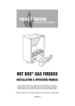
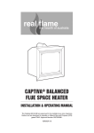
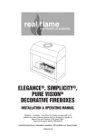
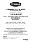
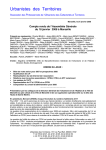
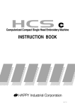
POWER FLUE®
INSTALLATION & OPERATING MANUAL
The Real Flame Power Flue system is approved to be installed with any
open fronted Real Flame gas fireplace. Approval Number 6094.
VERSION 9
WARRANTY
Provided your Real Flame Power Flue motor is installed in strict accordance with our installation
instructions, the motor is unconditionally guaranteed or twelve months from date of purchase.
This unconditional warranty covers parts and labour at our discretion taking into consideration normal wear
and tear and does not cover fires installed in outdoor settings.
INSTALLATION NOTICE
The installation of this appliance is only to be carried out by an authorised person in accordance
with the manufacturers instruction, local gas fitting regulations, AG601 installation codes for gas
burning appliances and any other relevant statutory regulations.
IMPORTANT NOTES
The Real Flame power flue system is designed and manufactured by Real Flame and is
approved to be installed with the following Real Flame Products.
•
MAGIGLO 320 PF
•
MAGIGLO 360 PF
•
MAGIGLO 400 PF
•
MAGIGLO 540 PF
•
MAGIGLO 750 PF
•
MAGIGOLO 540 DOUBLE
•
HEATSEEKER FIREBOX MODELS 600, 700, 850, 1000
•
HOTBOX FIREBOX
•
REGISTER FIREBOX
•
SIMPLICITY 850,1000, 1800
•
ELEGANCE 850, 1000, 1800
•
PURE VISION 850, 1000, 1800
THE INSTALLATION MANUAL OF THE REAL FLAME POWER FLUE SYSTEM IS TO
BE READ IN CONJUNCTION WITH THE INSTALLATION MANUAL OF THE REAL
FLAME PRODUCT BEING USED.
THE DESIGN OF THE REAL FLAME POWER FLUE SYSTEM IS SUBJECT TO
COPYRIGHT AND ALL INFRINGEMENTS WILL BE VIGOROUSLY PURSUED.
2
CONTENTS
Contents ..................................................................................................................3
Introduction ..............................................................................................................4
Installation ................................................................................................................4
Power Flue Kit ..........................................................................................................9
Motor Clearance.......................................................................................................8
Frameout ..................................................................................................................9
Motor exploded view..............................................................................................10
Dimensions ............................................................................................................11
Internal Motor .........................................................................................................12
External Motor ........................................................................................................12
Troubleshooting Electronic Ignition and Power Flue System ...............................13
Wiring Diagram ......................................................................................................15
Parts List ................................................................................................................15
Real Flame contact information .............................................................................16
3
INTRODUCTION - THE POWER FLUE SYSTEM
POWER FLUE DESIGN
A ‘flue’ using a fan to remove or assist in removing combustion products from an appliance, is
known as a ‘power flue’.
POWER FLUE APPLICATION
A power flue application can be used to enable a client to have a decorative fire with a horizontal
flue run or a vertical flue run where flue space is inadequate for the normal flue.
INSTALLATION INSTRUCTIONS
VENTILATION REQUIREMENTS
Air supply to the unit is to be in accordance with ventilation Clause 5.4 of the Gas Code 601.
Ventilation requirements do not change by using a power flue.
All Real Flame installation manuals have the ventilation areas clearly defined for each product.
ACCESS TO POWER FLUE MOTOR
Access must be provided to the flue motor, this access MUST be at least 400mm x 400mm.
There MUST be a minimum clearance of 250mm between the top of the motor and any fixed
object i.e. ceiling or stud work. This is so the top of the fan box can be removed.
WIRING OF THE POWER FLUE
All wiring for the power flue is carried out at the factory and plug connectors are fitted for easy
installation. The power supply for the power flue is via a 3-pin plug at the rear of the firebox that
can be plugged into a power socket within the cavity.
ISOLATION SWITCH
If the power point is within a cavity an isolation switch accessible from outside the cavity must be
provided.
WIRING CLEARANCES
Wiring must at all times have a clearance of at least 150mm from the flue.
FAN FAILURE SENSING DEVICE
All Real Flame Power Flue systems are fitted with a sensing device within the unit to ensure that,
in the event of flow failure, the safety shut off valve within the module will go into lockout and shut
off the gas supply to the unit.
‘LOCKOUT’
‘Lockout’ is the term used when the module in the unit sensors a fault. When a fault is detected by
the module it will shut off the gas and go into lockout. If this occurs contact the manufacturer.
4
INSTALLATION INSTRUCTIONS
(continued)
LOCATION OF FLUE TERMINAL FOR POWER FLUE
Listed below are the minimum clearances required for fan-assisted terminations:
1.
Below eaves, balconies and other projections. .........................................................200mm
2.
From the ground, above a balcony or other surface. ................................................300mm
3.
From a return wall or external corner..........................................................................300mm
4.
From a Gas meter. ....................................................................................................1000mm
5.
From an electricity meter or fuse box. ........................................................................500mm
6.
From a drainpipe or soil pipe. ......................................................................................75mm
7.
Horizontally from any building structure or obstruction facing a terminal.................500mm
8.
From any other flue terminal. Cowl, or combustion air intake. ..................................300mm
9.
Horizontally from any openable window, door, non-mechanical air inlet,
or any other opening into a building with the exception of sub floor ventilation.......300mm
10.
From a mechanical air inlet including a spa blower.................................................1000mm
11.
Vertically below an openable window, non-mechanical air inlet,
or any other opening into a building with the exception sub floor ventilation. ..........500mm
ELECTRICAL
SHOULD THE SUPPLY FLEX AT THE BACK OF THE FIREBOX BE DAMAGED, A SPECIALLY
PREPARED FLEX IS REQUIRED. FOR REPLACEMENT CONTACT THE MANUFACTURER.
THE ON/OFF WALL SWITCH MUST NEVER BE ATTACHED TO A METAL FRAME.
WARNING
Whenever servicing the power flue system, always turn off the electrical power supply and
close the manual gas control valve.
IMPORTANT INFORMATION
In addition to the instructions in this manual all national, state and local regulations must be
adhered to. These include but are not limited to:
• Australian Standards AS3000 - Electrical Installation.
• Australian Standards AS5601 - Gas Installation.
• Local Gas and Electrical Authority Regulations.
• Municipal Building Codes.
The power flue should be serviced every 12 months by an authorised technician. If repairs
are needed an authorised technician must carry them out.
FITTING THE MOTOR
The Power Flue motor has a 150mm spigot and a twin spigot of 150mm & 200mm. The single
spigot fits over the vertical flue and the 150/200mm flue attaches to the horizontal spigot.
5
INSTALLATION INSTRUCTIONS
(continued)
FLUE SIZE
All flue prior to the motor is 150mm/200mm twin skin flue and all flue after the motor is
150mm/200mm twin skin
HORIZONTAL FLUE RUN
The maximum length of horizontal flue run is to be 13.5 metres with a maximum of four (4) bends;
these bends can be 45° or 90°. The horizontal flue run is to have a grade downwards from the
motor to the termination.
VERTICAL FLUE RUN (see page 7)
The minimum vertical flue run is 900mm from the top of the firebox (1500mm from the floor). If a
longer vertical run is required twin skin flue 150mm & 200mm can be added between the muffler
top and the fan. The flue can be cut to the required height.
FLUE CLEARANCES
All flue clearances are as per the requirements listed in the heater specifications.
TERMINATION
The termination to be used for all horizontal installations is to be 150mm cowl that has been
approved as a horizontal cowl.
INSTALLATION OF POWER FLUE KIT
POWER FLUE MUFFLER
The power flue muffler has a spigot at each end. The end that attaches to the firebox has a spigot
equivalent to the inner flue spigot diameter of the firebox, the top of the muffler has a 150mm
spigot which the motor fits to, or the 150/200 twin skin flue if required. The flow arrow on the
muffler is to be pointing up.
WIRING (see wiring diagram page 15)
A 3 metre lead is supplied with the power flue, this lead has a different connection on each end,
one end is plugged into the connection on the left hand side of the firebox and the other end is to
be plugged into the fan. The wire coming from the rear of the firebox with the standard 3-pin plug
attached is to be plugged into a power point. A single gang wall switch is also supplied attached
to the 3 metres of lead; this wall switch is to be attached at a location accessible to the client. No
other wiring is required.
SERVICING OF THE POWER FLUE MOTOR
The Real Flame Power Flue motor is designed so as to make servicing the motor a simple task.
The power lead connected to the motor is to be disconnected (unplugged) and the two side clips
are to be undone, the fan motor will then lift out for servicing. The fan Motor box connected to the
flue does not have to be disconnected from the flue.
6
POWER FLUE KIT (Here shown with Heatseeker firebox)
150mm Gas
gas cowl
100mm
cowl // Kit
Kit
Twin
Twin Skin
Skin Flue
Flue 150/200mm
100mm & 180mm
Electrical
Wiring
between
Fan / Unit / Kit
Fan Casing / Kit
Twin Skin Flue 150mm /200mm
Optional for additional height if required
Powered flue kit comprising:
(Indicated on Diagram as “Kit”)
1 x Fan motor
1 x Control module
1 x Electronic ignition to gas fire
1 x Muffler
1 x Sail switch
1 x All wiring from motor to gas fire
1 x 150mm
100mm gas cowl
Baffled Flue / Kit
Z/C Heatseeker Series
Wall switch for On/Off / Kit
Standard Power Lead
FFO
OL
P
I
Control Module / Kit
Electronic Ignition / Kit
7
POWER FLUE MOTOR CLEARANCE
Minimum clearance
250mm
Ensure there is
adequate ventilation
within this cavity to
prevent motor overheating.
150mm/200mm
twin skin flue - optional
for additional height
Minimum
Baffle Height 980mm
height
and diameter 350mm
8
TYPICAL POWER FLUE FRAMEOUT
9
POWER FLUE MOTOR
Motor
Motor
Capacitor
4 mf
Pressure
Differential Switch
Fan
Fan Casing
10
DIMENSIONS
Power Flue Motor
A
B
C
D
E
F
G
H
302
348
345
55
90
20
200
150
I
J
K
L
M
N
O
P
20
120
60
105
75
45
112
13
Power Flue Flush
Termination 500 x 500
Power Flue Flush
Termination 300 x 300
11
INTERNAL MOTOR
500mm
Top Termination
300mm min.
Access
Panel
Min. Distance
Domestic: 220mm
Industrial: 320mm
150mm x 200mm flue extension
200mm
Motor
Termination
150mm x 200mm twin
skin flue (if required)
Baffle
900mm
Heater
25mm
Flue
Minimum 25mm clearance
from outer flue to
combustible interior.
NOTE:
1.
Maximum of 4 elbows, 45° or 90°.
2.
Allow 400mm x 400mm access panel for service of motor.
EXTERNAL MOTOR
25mm clearance
200mm
340mm
150mm x 200mm flue extension
150mm x 200mm twin
skin flue (if required)
Miniumum
1290mm
900mm
Baffle
Heater
NOTE:
1.
12
Maximum of 4 elbows, 45° or 90°.
External Motor
TROUBLE SHOOTING FOR ELECTRONIC IGNITION AND
POWER FLUE SYSTEM.
Symptom
Possible Cause
Corrective Action
Fire turned on and
nothing happens
No Power to Module
Connect Power
Fire turned on and
motor starts but
there is no spark
Pressure switch not
operating
Check pressure switch
Fire sparks when
turned on but will
not ignite
A. No Gas
Connect Gas.
B. Sparker is to far from
metal
Adjust sparker so it cross lights to metal.
C. Pressure switch
(Power Flue) is not
operating correctly.
Remove fan from housing and check that small tube
supplying air to pressure switch has not moved or been
damaged.
C. Valve solenoids are
faulty
Check solenoids
D. Solenoid wires to
module not connected
correctly
Check that the four pin plug from the valve has been
connected correctly
A. Something is touching
the heat sensor
Ensure that nothing is touching the sensor which is located
behind the cover plate at front of burner.
B. The power polarity is
reversed
Check polarity
A. Insufficient air for
burner to operate
correctly
Check that the unit has correct ventilation as per Installation
manual.
B. Pressure switch not
operating correctly
Check air supply tube to pressure switch.
Fire ignites and then
shuts down within a
couple of seconds
Fire ignites and
shuts down after
several minutes
13
TROUBLE SHOOTING FOR ELECTRONIC IGNITION AND
POWER FLUE SYSTEM. (continued)
The power flue and electronic control box have a red LED light that indicates the
possible cause of a problem, the LED light will flash in different sequences for
different problems, the most common are:-
14
Long Flash
Short Flash
1
0
Normal Running State.
1
1
Flame Failure.
1
2
Waiting for pressure switch ON
1
3
Waiting for pressure switch OFF
2
1
Maximum retries exceeded
POWER FLUE WIRING DIAGRAM
TECHRITE POWER FLUE
CONTROL MODULE
Sparker
Heat Sensor
LED Indicator
Pressure
Switch
Power
Fan
Double
Block
Solenoid
NOTE
For C Bus and/or fresh air damper interlock systems, please contact us for wiring diagrams and
relevant system instructions at [email protected]
PARTS LIST
PART No.
DESCRIPTION
1.
Dungs BM.740-007 double block solenoid valve
2.
Dungs DGAI.73 Module 5.1.3.
3.
Electronic Ignition Sparker
4.
Electronic Flame Sensor
5.
Ecofit 2GTA35 Motor. Complete with ‘sail’ switch.
6.
900mm Real Flame Power Flue Muffler.
15
REAL FLAME PTY LTD
ABN 76 006 311 155
Head Office/Factory/Showroom
1340 Ferntree Gully Rd.
Scoresby Vic 3179
Ph: (03) 8706 2000 Fax: (03) 8706 2001
E-mail: [email protected]
Richmond - VIC Showroom
300 Swan St.
Richmond Vic 3121
Ph: (03) 9428 4443 Fax: (03) 9428 4445
Dandenong - VIC Showroom
9 Lonsdale St.
Dandenong Vic 3175
Ph: (03) 9791 9285 Fax: (03) 9791 9662
Geelong - VIC Showroom
1/2A Gordon Avenue.
Geelong West Vic 3218
Ph/Fax: 5229 0844
E-mail: [email protected]
Sydney - NSW Showroom
654 Pacific Highway.
Chatswood NSW 2067
Ph: (02) 8905 0189 Fax: (02) 8905 0192
E-mail: [email protected]
Miranda - NSW Showroom
36 Kareena Rd
Miranda NSW 2228
Ph: (02) 8513 6202 Fax: (02) 9520 1974
E-mail: [email protected]
Adelaide - SA Showroom
173 -175 Magill Rd.
Norwood SA 5067
Ph: (08) 8132 0371 Fax: (08) 8132 1687
E-mail: [email protected]
Miton - QLD Showroom
46 Douglas St,
Milton QLD 4064
Ph: (07) 3368 2011
Perth – WA Showroom
47-53 McDonald St East,
Osborne Park WA 6017
Ph: (08) 9444 9900 Fax: (08) 9444 9800
Fyshwick – ACT Showroom
88 Wollongong St,
Fyshwick ACT 2609
Ph: (02) 6280 5522