1
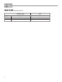
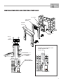
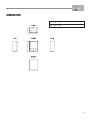
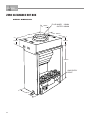
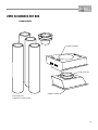
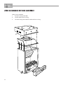
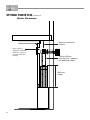
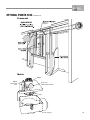
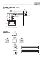
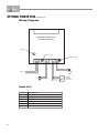
®
HOT BOX GAS FIREBOX
INSTALLATION & OPERATING MANUAL
The Hot Box Gas Firebox is approved to be installed into a masonary
fireplace and as a zero clearance firebox and is designed to operate on
Natural Gas and Propane (LPG) gases ONLY. Approval Number 6094.
Installed primarily as a decorative appliance. Not certified as a Space Heater.
VERSION 8
WARRANTY
Provided your Real Flame gas fire is installed in strict accordance with our installation instructions, the
firebox is unconditionally guaranteed for ten years and all other parts for twelve months from date of
purchase.
This unconditional warranty covers part and labour at our discretion taking into consideration normal wear
and tear and does not cover fires installed in outdoor settings.
INSTALLATION NOTICE
The installation of this appliance is only to be carried out by an authorised person in accordance
with the Manufacturer’s Instructions, local gas fitting regulations, AG601 installation code for gas
burning appliances and any other relevant statutory regulations.
In all cases the installation of this appliance shall meet the requirements as set out in AS5601/AG601.
NOTE: A slight smell may be apparent for the first few hours of use. This is due to the heat
resistant paint curing. It is recommended to open windows in the room for the first lighting of the
fire. In some instances a slight discolouration may occur inside the firebox. This is a normal
condition and is not covered by warranty.
IMPORTANT SAFETY NOTICE
DO NOT PLACE ARTICLES ON OR AGAINST THIS APPLIANCE.
DO NOT USE OR STORE FLAMMABLE MATERIAL NEAR THE APPLIANCE.
DO NOT SPRAY AEROSOLS IN THE VICINITY OF THIS APPLIANCE WHILST IT IS IN OPERATION.
CARE MUST BE TAKEN TO ENSURE THAT ANY RETURN AIR REGISTER OR EXHAUST SYSTEM
DOES NOT ADVERSLEY AFFECT THE OPERATION OF THE APPLIANCE OR DRAUGHT OF
CHIMNEY OR FLUE.
WARNING
This firebox has a naked flame, care should be taken when it is operating if children or the infirm
are in close proximity. A safety screen is recommended if constant supervision is not possible.
VENTILATION REQUIREMENTS
2
MODEL
EFFECTIVE VENTILATION
Hot Box
40,000 sq mm
CONTENTS
Contents ..................................................................................................................3
Data Plate.................................................................................................................4
Installation Instructions ............................................................................................5
Commissioning Procedure ......................................................................................5
Clearances from combustibles................................................................................6
Installation into an existing fireplace .......................................................................7
Dimensions ..............................................................................................................8
Frameout into room specification sheet 1.............................................................10
Zero Clearance Hot Box ........................................................................................12
Overall Dimensions ................................................................................12
Components ...........................................................................................13
Assembly ................................................................................................14
Optional Power Flue ..............................................................................................15
Introduction ............................................................................................15
Installation ..............................................................................................................16
Motor Clearance .....................................................................................18
Frameout ................................................................................................19
Motor exloded view ................................................................................19
Internal Motor .........................................................................................20
External Motor ........................................................................................21
Wiring Diagram.......................................................................................22
Parts List .................................................................................................23
Troubleshooting Electronic Ignition and Power Flue System...............................24
Real Flame contact information.............................................................................28
3
DATA PLATE (Affixed to burner)
4
NATURAL GAS
LPG
Injector
2.5
1.3
Mj/Hr
26
23
P.T.P.
0.8
2.7
INSTALLATION INSTRUCTIONS
INSTALLATION INTO AN EXISTING FIREPLACE
The Hot Box system is designed to be installed behind a cast iron insert or fascia.
1.
Check that the fireplace and chimney are in working order, sound condition and clean and
free from obstructions. Any cracks or gaps found in the masonary of the fireplace, must be
sealed prior to the installation of the Hot Box.
2.
Measure the fireplace opening to ensure that the Hot Box will fit into the opening.
3.
If fitting the Hot Box into an existing fireplace, using the existing cast iron insert, you will need
to remove the back from the cast iron insert. This will require the mantelpiece and insert to be
removed from the fireplace prior to installing the Hot Box.
4.
Install Hot Box by placing it centrally in the fireplace opening and fit cast iron fascia up to the
Hot Box, ensuring that the fascia is firmly touching against the brickwork of the fireplace and
the Hot Box. Remove fascia and permanently fix the Hot Box to hearth using the location lugs.
5.
Before sealing the cast iron fascia to the brickwork have your gas fitter supply a 15mm copper
pipe into the fireplace and Hot Box through the hole provided for connection to the Magiglo
burner.
6.
Once the gas supply has been installed into the Hot Box fit and seal the cast iron fascia to the
brick work and install your desired mantel piece to complete your fireplace.
7.
Have your gas fitter refer to the Magiglo Series Installation Instructions for connection and set
up of the Magiglo 360 Series Gas Coal Set.
8.
A 225mm approved gas cowl is required to be fitted to the top of chimney to stop down draft
and rain entering into chimney.
9.
Ventilation of 40,000 sq mm must be provided to outside air for the room that the Hot Box is
installed. Four standard vents is normally enough. Check that they are clear of blockages.
IMPORTANT
After installing gas coal/log set the following commissioning procedure must take place
before leaving premises.
COMMISSIONING PROCEDURE
Once the fire is installed and operational, the installer must check for spillage. Carry out the lighting
procedure and turn the fire to high. Allow to warm up for 10 minutes and then using a smoke match,
set 25mm down and 25mm inside of the fire opening, run the match across the width of the opening
to check that all of the smoke is drawn away.
Repeat the test with doors and windows to the premises open and closed, and with any extractor
fans in the same room or adjacent rooms running on high. The fire should continue to clear its
combustion products. Also operate any other flued appliances in the same or neighbouring rooms
and ensure they continue to function satisfactorily as multiple flues can work against one another.
If spillage is detected during this procedure it could indicate a faulty flue or lack or ventilation. If the
problem cannot be rectified immediately, disconnect the appliance, and advise the customer not to
use the appliance until the problem has been resolved.
The customer should always be advised of the need for regular servicing and checks to ensure the
continued clearance of combustion waste products.
NOTE: A slight smell may be apparent for first few hours of use. This is due to the heat resistant
paint curing. It is recommended to open windows in room for the first lighting.
5
COMMISSIONING PROCEDURE
(continued)
WARNING
Care must be taken to ensure that any return air register exhaust system does not
adversely affect the operation of the appliance or draught of chimney or flue.
“DO NOT place articles on or against this appliance.”
“DO NOT use or store flammable materials near this appliance.”
“DO NOT spray aerosols in the vicinity of this appliance while it is in operation.”
CLEARANCES FROM COMBUSTIBLES
25mm
425mm
Cast iron
fascia
930mm
DIAGRAM 1.
Floor
Sides
Back
Top
Flue Outer
PLAN
0 mm
25 mm
25 mm
100 mm
25 mm
A minimum of 3.6m
flue is required to
protrude 500mm
above roof line.
Flue can be offset
with two 45° bends,
no more than 20% of
overall height of flue.
6
INSTALLATION INTO AN EXISTING FIREPLACE
HOT BOX
CAST IRON
FASCIA
MANTEL
PIECE
GAS INLET
HOLE
225mm
GAS
COWL
ENSURE THAT EXHAUST PORT
IS NOT RESTRICTED
IN ANY WAY.
EXISTING
CHIMNEY
SEAL FASCIA
TO BRICKWORK
7
HOT BOX FOR EXISTING FIREPLACE
OVERALL DIMENSIONS
230
455
260
135
350
570
GAS ENTRY
POINT
HEARTH
LOCATION
LUGS
8
DIMENSIONS
A
B
C
570
455
230
9
FRAMEOUT INTO ROOM SPECIFICATION SHEET 1
D
90mm x 38mm
ON EDGE
C
25mm
FRAMEOUT DIMENSIONS
Model
Hot Box
10
A
800
B
510
C
425
A
B
D
1800
25mm
FRAMEOUT INTO ROOM SPECIFICATION SHEET 1
SPECIFICATION SHEET 1.
150mm
INNER FLUE
200mm
OUTER FLUE
CAST IRON
FASCIA
HOT BOX
MANTEL
PIECE
GAS INLET
HOLE
11
ZERO CLEARANCE HOT BOX
OVERALL DIMENSIONS
170mm
460mm
FLUE INNER 150MM
OUTER 200MM
305mm
130mm
135mm
570mm
GAS ENTRY
POINT
230mm
12
ZERO CLEARANCE HOT BOX
COMPONENTS
OUTER CASING
FLUE COLLAR
INNER CASING
3.6M FLUE KIT
COMPLETE WITH COWL
13
ZERO CLEARANCE HOT BOX ASSEMBLY
Using screws provided:
14
1.
Fit inner casing to Hot Box.
2.
Fit flue collar to inner casing.
3.
Fit outer casing over both flue collar and inner casing.
ASSEMBLY
OPTIONAL POWER FLUE
THE INSTALLATION MANUAL OF THE REAL FLAME POWER FLUE SYSTEM IS TO BE READ IN
CONJUNCTION WITH THE INSTALLATION MANUAL OF THE REAL FLAME PRODUCT BEING
USED. THE DESIGN OF THE REAL FLAME POWER FLUE SYSTEM IS SUBJECT TO COPYRIGHT
AND ALL INFRINGEMENTS WILL BE VIGOROUSLY PURSUED.
Introduction - the Power Flue System
POWER FLUE DESIGN
A ‘flue’ using a fan to remove or assist in removing combustion products from an appliance, is
known as a ‘power flue’.
POWER FLUE APPLICATION
A power flue application can be used to enable a client to have a decorative fire with a horizontal
flue run or a vertical flue run where flue space is inadequate for the normal flue.
Installation Instructions
VENTILATION REQUIREMENTS
Air supply to the unit is to be in accordance with ventilation Clause 5.4 of the Gas Code 601.
Ventilation requirements do not change by using a power flue.
All Real Flame installation manuals have the ventilation areas clearly defined for each product.
ACCESS TO POWER FLUE MOTOR
Access must be provided to the flue motor, this access MUST be at least 400mm x 400mm.
There MUST be a minimum clearance of 250mm between the top of the motor and any fixed
object i.e. ceiling or stud work. This is so the top of the fan box can be removed.
WIRING OF THE POWER FLUE
All wiring for the power flue is carried out at the factory and plug connectors are fitted for easy
installation. The power supply for the power flue is via a 3-pin plug at the rear of the firebox that
can be plugged into a power socket within the cavity.
ISOLATION SWITCH
If the power point is within a cavity an isolation switch accessible from outside the cavity must be
provided.
WIRING CLEARANCES
Wiring must at all times have a clearance of at least 150mm from the flue.
FAN FAILURE SENSING DEVICE
All Real Flame Power Flue systems are fitted with a sensing device within the unit to ensure that,
in the event of flow failure, the safety shut off valve within the module will go into lockout and
shut off the gas supply to the unit.
‘LOCKOUT’
‘Lockout’ is the term used when the module in the unit senses a fault. When a fault is detected
by the module it will shut off the gas and go into lockout. If this occurs contact the manufacturer.
15
OPTIONAL POWER FLUE (continued)
Installation Instructions
(continued)
LOCATION OF FLUE TERMINAL FOR POWER FLUE
Listed below are the minimum clearances required for fan-assisted terminations:
1.
Below eaves, balconies and other projections..........................................................200mm
2.
From the ground, above a balcony or other surface. ...............................................300mm
3.
From a return wall or external corner. ........................................................................300mm
4.
From a Gas meter. ....................................................................................................1000mm
5.
From an electricity meter or fuse box. .......................................................................500mm
6.
From a drainpipe or soil pipe. ......................................................................................75mm
7.
Horizontally from any building structure or obstruction facing a terminal................500mm
8.
From any other flue terminal. Cowl, or combustion air intake. .................................300mm
9.
Horizontally from any openable window, door, non-mechanical air inlet,
or any other opening into a building with the exception of sub floor ventilation. ....300mm
10.
From a mechanical air inlet including a spa blower................................................1000mm
11.
Vertically below an openable window, non-mechanical air inlet,
or any other opening into a building with the exception sub floor ventilation..........500mm
ELECTRICAL
SHOULD THE SUPPLY FLEX AT THE BACK OF THE FIREBOX BE DAMAGED, A SPECIALLY
PREPARED FLEX IS REQUIRED. FOR REPLACEMENT CONTACT THE MANUFACTURER.
THE ON/OFF WALL SWITCH MUST NEVER BE ATTACHED TO A METAL FRAME.
WARNING
Whenever servicing the power flue system, always turn off the electrical power supply and
close the manual gas control valve.
IMPORTANT INFORMATION
In addition to the instructions in this manual all national, state and local regulations must
be adhered to. These include but are not limited to:
• Australian Standards AS3000 - Electrical Installation.
• Australian Standards AS5601 - Gas Installation.
• Local Gas and Electrical Authority Regulations.
• Municipal Building Codes.
The power flue should be serviced every 12 months by an authorised technician. If repairs
are needed an authorised technician must carry them out.
FITTING THE MOTOR
The power flue motor has a 150mm spigot and a twin skin spigot of 150mm & 200mm. The single
spigot fits over the vertical flue and the 150mm/200mm flue attaches to the horizontal spigot.
FLUE SIZE
16
All flue prior to the motor is 150mm/200mm twin skin and all flue after the motor is 150mm/200mm
twin skin.
OPTIONAL POWER FLUE (continued)
Installation Instructions
(continued)
HORIZONTAL FLUE RUN
The maximum length of horizontal flue run is to be 13.5 metres with a maximum of four (4)
bends; these bends can be 45° or 90°. The horizontal flue run is to have a grade downwards
from the motor to the termination.
VERTICAL FLUE RUN
The minimum vertical flue run is 900mm from the top of the firebox (1500mm from the floor). If a
longer vertical run is required twin skin flue 150mm & 200mm can be added between the muffler
top and the fan. The flue can be cut to the required height.
FLUE CLEARANCES
All flue clearances are as per the requirements listed in the heater specifications.
TERMINATION
The termination to be used for all horizontal installations is to be 150mm cowl that has been
approved as a horizontal cowl.
Installation of Power Flue Kit
POWER FLUE MUFFLER
The power flue muffler has a spigot at each end. The end that attaches to the firebox has a
spigot equivalent to the inner flue spigot diameter of the firebox, the top of the muffler has a
150mm spigot which the motor fits to, or the 150/200 twin skin flue if required. The flow arrow
on the muffler is to be pointing up.
WIRING (see wiring diagram page 22)
A 3 metre lead is supplied with the power flue, this lead has a different connection on each end,
one end is plugged into the connection on the left hand side of the firebox and the other end is
to be plugged into the fan. The wire coming from the rear of the firebox with the standard 3-pin
plug attached is to be plugged into a power point. A single gang wall switch is also supplied
attached to the 3 metres of lead; this wall switch is to be attached at a location accessible to the
client. No other wiring is required.
SERVICING OF THE POWER FLUE MOTOR
The Real Flame Power Flue motor is designed so as to make servicing the motor a simple task.
The power lead connected to the motor is to be disconnected (unplugged) and the two side clips
are to be undone, the fan motor will then lift out for servicing. The fan Motor box connected to
the flue does not have to be disconnected from the flue.
17
OPTIONAL POWER FLUE (continued)
Motor Clearance
Minimum clearance
250mm
Ensure there is
adequate ventilation
within this cavity to
prevent motor overheating.
150mm/200mm
twin skin flue - optional
for additional height
Minimum
height
18
OPTIONAL POWER FLUE (continued)
Frameout
T
IMPORTANT
Motor
Motor
Motor
Capacitor
4 mf
Pressure
Differential Switch
Fan
Fan Casing
19
OPTIONAL POWER FLUE (continued)
Internal Motor
500mm
Top Termination
300mm min.
Access
Panel
Min. Distance
Domestic: 220mm
Industrial: 320mm
150mm x 200mm flue extension
200mm
Motor
Termination
150mm x 200mm twin
skin flue (if required)
900mm
Baffle
Heater
25mm
Flue
Minimum 25mm clearance
from outer flue to
combustible interior.
NOTE:
1.
Maximum of 4 elbows, 45° or 90°.
2.
Allow 400mm x 400mm access panel for service of motor.
Flush Cowl Terminations 300x300
115
300
22
154
300
FRONT
152 182
SIDE
REAR
Flush Cowl Terminations 500x500
115
500
154
22
152 182
500
20
FRONT
SIDE
REAR
OPTIONAL POWER FLUE (continued)
External Motor
25mm clearance
200mm
340mm
External Motor
150mm x 200mm flue extension
150mm x 200mm twin
skin flue (if required)
Miniumum
1290mm
900mm
Baffle
Heater
NOTE:
1.
Maximum of 4 elbows, 45° or 90°.
Fan Box
Dimensions
A
B
C
D
E
F
G
H
302
348
345
55
90
20
200
150
I
J
K
L
M
N
O
P
20
120
60
105
75
45
112
13
21
OPTIONAL POWER FLUE (continued)
Wiring Diagram
TECHRITE POWER FLUE
CONTROL MODULE
Sparker
Heat Sensor
LED Indicator
Pressure
Switch
Power
Fan
Parts List
PART No.
1.
Dungs BM.740-007 double block solenoid valve
2.
Dungs DGAI.73 Module 5.1.3.
3.
Electronic Ignition Sparker
4.
Electronic Flame Sensor
5.
Ecofit 2GTA35 Motor. Complete with ‘sail’ switch.
6.
22
DESCRIPTION
900mm Real Flame Power Flue Muffler.
Double
Block
Solenoid
TROUBLE SHOOTING FOR ELECTRONIC IGNITION AND
POWER FLUE SYSTEM.
Symptom
Possible Cause
Fire turned on and
nothing happens
No Power to Module
Fire turned on and
motor starts but
there is no spark
Pressure switch not
operating
Check pressure switch
Fire sparks when
turned on but will
not ignite
A. No Gas
Connect Gas.
B. Sparker is to far from
metal
Adjust sparker so it cross lights to metal.
C. Pressure switch
(Power Flue) is not
operating correctly.
Remove fan from housing and check that small tube
supplying air to pressure switch has not moved or been
damaged.
C. Valve solenoids are
faulty
Check solenoids
D. Solenoid wires to
module not connected
correctly
Check that the four pin plug from the valve has been
connected correctly
A. Something is touching
the heat sensor
Ensure that nothing is touching the sensor which is located
behind the cover plate at front of burner.
B. The power polarity is
reversed
Check polarity
A. Insufficient air for
burner to operate
correctly
Check that the unit has correct ventilation as per
Installation manual.
B. Pressure switch not
operating correctly
Check air supply tube to pressure switch.
Fire ignites and then
shuts down within a
couple of seconds
Fire ignites and
shuts down after
several minutes
Corrective Action
Connect Power
23
TROUBLE SHOOTING FOR ELECTRONIC IGNITION AND
POWER FLUE SYSTEM. (continued)
The power flue and electronic control box have a red LED light that indicates the
possible cause of a problem, the LED light will flash in different sequences for
different problems, the most common are:-
24
Long Flash
Short Flash
1
0
Normal Running State.
1
1
Flame Failure.
1
2
Waiting for pressure switch ON
1
3
Waiting for pressure switch OFF
2
1
Maximum retries exceeded
25
26
27
REAL FLAME PTY LTD
ABN 76 006 311 155
Head Office/Factory/Showroom
1340 Ferntree Gully Rd.
Scoresby Vic 3179
Ph: (03) 8706 2000 Fax: (03) 8706 2001
E-mail: [email protected]
Richmond - VIC Showroom
300 Swan St.
Richmond Vic 3121
Ph: (03) 9428 4443 Fax: (03) 9428 4445
Geelong - VIC Showroom
1/2A Gordon Avenue.
Geelong West Vic 3218
Ph/Fax: (03) 5229 0844
E-mail: [email protected]
Sydney - NSW Showroom
654 Pacific Highway.
Chatswood NSW 2067
Ph: (02) 8905 0189 Fax: (02) 8905 0192
E-mail: [email protected]
Miranda - NSW Showroom
36 Kareena Rd
Miranda NSW 2228
Ph: (02) 8513 6202 Fax: (02) 9520 1974
E-mail: [email protected]
Adelaide - SA Showroom
173 -175 Magill Rd.
Norwood SA 5067
Ph: (08) 8132 0371 Fax: (08) 8132 1687
E-mail: [email protected]
Miton - QLD Showroom
46 Douglas St,
Milton QLD 4064
Ph: (07) 3368 2011
Perth – WA Showroom
47-53 McDonald St East,
Osborne Park WA 6017
Ph: (08) 9444 9900 Fax: (08) 9444 9800
Fyshwick – ACT Showroom
88 Wollongong St,
Fyshwick ACT 2609
Ph: (02) 6280 5522