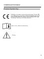
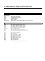
1
Barton Convertible®
I-400 / I-700
(b1041-TS-GEL / b1071-TS-GEL)
Owner Operation Manual
■ This Operation Manual provides important instructions for the safe
use of Barton Convertible® I-400/I-700 chairs. Please read this manual
carefully and use Convertible® I-400/I-700 chairs only after you have
developed a full understanding about their safe and correct use.
■ Do not use the Convertible® without
first reading and
understanding
the transfer
procedures.
■ Keep this manual
where you can
consult it whenever
necessary.
■ The information
contained in this
manual is subject
to change without
notice.
www.bartonmedical.com
TM
The Barton Medical is a trademark of the Barton Medical Corporation.
Document Control # OM 015 Rev. D (Released 10/29/10)
1
WARNING
Do not operate this equipment without first reading
and understanding this manual. If you are unable to
understand the warnings, cautions, and instructions,
contact a healthcare professional, dealer, or technical
personnel, if applicable, before attempting to use this
equipment. Otherwise injury or damage may result.
SAVE THESE INSTRUCTIONS
Indications for Use:
The Convert table® I-400 / I-700 I-Series Positioning and Transfer Chair is a
mechanical positioning chair that can be adjusted to various positions. The
device is used to alter postural positions and to provide a means of
transferring a patient horizontally from a height adjustable bed or trolley, to
the chair and vice versa. The chair can then be transformed from a supine
position into the sitting position without ever lifting the patient.
Device Description
The Convert table® Positioning and Transfer Chair construction is made of
steel tubular components, on to which is fitted foam filled upholster y. The
mechanism allows the Conver tible® Positioning and Transfer Chair to
transform from the horizontal supine position into a chair, which can then be
tilted. The reclining function allows the Chair and patient pro le to change
from a sitting position to a horizontal or supine position suitable for
transferring. The Tilt-in-Space function allows the I-400 / I-700 to be
independently inclined to the rear ( Tilt-in-Space).
Contraindications
The Conver tible® Positioning and Transfer Chair is not intended for patient
transport t in a moving vehicle of any type.
Only use The Bar ton Patient Transfer System with the Conver tible® I-400 / I700 Positioning and Transfer Chair.
2
The Conver tible® Positioning and Transfer Chair is intended for indoor
ambient environments. It is not intended for use in high moisture areas
(i.e. showers, pool therapy), extreme temperature, humidity, or pressure
environments.
Risks and Benefits
The decision to use the Conver tible® Positioning & Transfer Chair must
be made by a trained caregiver. In all cases this chair can only be
articulated when the patient is attended.
The Conver tible® Positioning & Transfer Chair is ideal for moving those
patients who are unable to move themselves. The patient can be moved
without the indignity, discomfort t, and medical limitations of traditional
mobile hoists.
The patient will always be suppor ted either on the bed and/or the chair
and is never suspended. Therefore the patient can be moved with
reduced risk of injury y to either patient or caregiver.
The Conver tible® Positioning & Transfer Chair is easy to operate by
trained personnel.
Device Expectations
The device is used to alter postural positions and to provide a means of
transferring a patient horizontally from a height adjustable bed or
trolley, to the chair and vice versa.
Environmental Issues
After life of the product:
•
•
•
Recycle in accordance with the recycling codes of your country.
Recycle all metal and plastic par ts in compliance with all applicable
regulations in your region.
Inquire at your local disposal management and recycling center for
local codes.
3
Contents
Descriptive Information..............................................................
1
Table of Contents...........................................................................
4
1
Part names........................................................................................
5
2
Safety notes.....................................................................................
6
- Warnings........................................................................................
- Cautions.........................................................................................
7
8
Making adjustments.....................................................................
9
- Seat height adjustments ........................................................
10/11
- Height/depth/angle adjusting levers.................................
12
- Headrest........................................................................................
13
- Footrest..........................................................................................
14
3
- Leg rest.........................................................................................
4
15/16
Operating the Convertible I-400/I-700...................................
17
- Casters............................................................................................
18
- Tilting operation.........................................................................
19
- Side rails........................................................................................
20
- Chair brackets..............................................................................
21/22
5
Troubleshooting the Convertible I-400/I-700.....................
23
6
Maintaining the Convertible I-400/I-700..............................
24/25
7
Specifications..................................................................................
26
8
Warranty and service....................................................................
27
Limited warranty...........................................................................
9 Additional Information……………………………………….
28/29
30
10
Manufacturers Approved Accessories…………………….
31
4
1 Part names
Headrest
Headrest handle
Chair bracket (headrest)
Backrest
Plastic bearing
Armrest
Armrest height adjustment knob
Seat
Calf Pad
Leg Rest
Plastic bearing
Footrest height adjusting lever (Back
side) Chair bracket (footrest)
Footrest
Footrest guard
Headrest depth/angle
adjusting lever
Push handle
Headrest height
adjusting lever
Caster control pedal
Leg rest angle
adjusting lever
Front steering caster
Rear Casters
5
2 Safety notes
You must understand the warnings and cautions in this manual to use the Barton
Convertible® safely. Please read all of these instructions carefully to avoid personal
injury or property damage.
Tie-Down Restraints and Seat Positioning Straps
The Department of Transportation has not approved any tie-down system for
transporting an occupied Convertible® in a moving vehicle of any type. The manufacturer does not recommend transporting the Convertible® in vehicles of any kind while
the equipment is occupied.
It is the manufacturer's position that users of the Convertible® should be transferred
to appropriate seating in vehicles and be transported with the use of standard auto
industry restraints. The manufacturer cannot and does not recommend any transportation system for the Convertible®.
As regards to restraints and seat positioning straps, therapists and other healthcare
professionals are obligated to determine if a seat positioning strap is required to
ensure the safe operation of this equipment by the user. Serious injury can occur in
the event of a fall from a Convertible® chair.
Weight Limitations
The maximum occupant weight for the Convertible® I-400 is 400 lb. / 181 Kg
The maximum occupant weight for the Convertible® I-700 is 700 lb. / 317 Kg
People who weigh more cannot use these models.
Some patients' physical limitations or weights present the potential for injuring an
attendant or the patient when reclining the Convertible®.
When in doubt, ensure that additional attendants are present.
Before using the Convertible®, verify that:
1. All casters work properly (4-caster lock, 4-caster free, steering lock).
2. The equipment reclines smoothly and stops in any desired position.
3. The height and angle of the footrest and the height, angle, and depth of the
headrest can be adjusted properly.
4. The side rails can be locked and released reliably.
5. The equipment tilt smoothly and stops in any desired position.
6. All height adjustment screws are securely tightened.
6
2 Safety notes (continued)
WARNING
Please heed the following warning. Failure to observe them
can lead to an accident and can seriously injure the patient.
Warnings
After any adjustment, repair, or service and
before use, ensure that all attaching
hardware is tightened securely.
Do not attempt to move the Convertible® in
the fully reclined or nearly reclined position.
Do not
move!
Do not push or pull the Convertible® by the
headrest handle.
To maintain maximum stability when
reclining / inclining the Convertible®, position
the patient with arms and legs inside the chair
and clear of moving parts.
Inside
Raised armrest
Do not confuse the headrest and
footrest when placing the patient
in the prone position.
headrest
Do not jump up
and down on the
back cushion or
seat cushion.
footrest
7
2 Safety notes (continued)
Warnings
Do not use stairs or
escalators to move
an occupied
Convertible® in any
position.
Take special care to lock the
casters securely.
Never sit or lean on the headrest or
the leg rest when the Convertible® is
in the supine position.
The maximum occupant weight for the
I-400 is 400 lb. / 181 Kg
The maximum occupant weight for the
I-700 is 700 lb. / 317 Kg
People who weigh more cannot use
these models.
The Convertible® is not designed to properly
support a patient receiving CPR. This will
change the center of gravity and may cause
the chair to tip over.
Ensure that all persons and objects
are clear of the Convertible® when you
recline/incline the equipment.
Never disassemble or remodel the
Convertible®.
Take special care
when going up or
down a ramp. Never park the
Convertible® on a
slope. Never leave
an occupied chair
unattended. Only
operate chair on
handicap grade
access ramp.
Protective foot wear is recommended
to avoid injury to sensitive skin due to
contact with the footrest hinge bracket.
Do not attempt to lift the Convertible® I400 / I-700 chairs by holding the leg rest
assembly.
8
2 Safety notes (continued)
Cautions
Please heed the following cautions. Failure to observe them
may result in personal injury or mechanical failure.
Do not use the footrest as a step when
you sit on or get off of the Convertible®.
Do not attempt to use the caster
locks to stop the Convertible® in motion.
These locks are not designed to be
braking devices.
Always raise the armrests whenever the
patient is in the supine position.
The armrests act as side rails.
Do not attempt to move the Convertible® by
holding the armrest.
The Convertible® is designed for a single
occupant. Never allow two or more people
nor place any other heavy object on it.
Do not use near an open flame (stove,
cigarette, etc.) or an extreme heat
source.
WARNING:
The Convertible® I-400 / I-700 is not designed as
a weight training or rehabilitation apparatus.
Never use it for such purposes.
Warning: Always PULL the patient
and chair backwards over a bump or
threshold.
Do Not attempt to PUSH the chair
over a bump or threshold as this can
cause the risk for the chair to tip
forward. This can cause serious injury.
Do Not use the chair if it has any missing or
abnormal parts.
.
Use only parts and accessories authorized
by the manufacturer.
9
3 Making adjustments
Seat height adjustments
Seat height is adjustable within 4 inches
(101.6mm) range
Seat level
4 inches
Floor
How to adjust
Allen wrench
1
3
2
front
rear
4
Raising the height
Up
1
2
3
1. With Allen wrench(5mm), loosen 6 bolts ①②③ on height adjust
die casts on both left and right side of the Convertible®. Be careful
not to unscrew the bolts.
2. Using the Allen wrench, rotate ④ bolt counterclockwise alternating
between left & right sides at 1/2" (12.7mm) increments.
3. Repeat 2 until the seat height reaches desired height.
① and ② on both sides.
5. After tightening ① and ②, tighten bolt ③ on both sides. Do
Not Set Above The 4” (101.6mm) Mark.
4. Tighten bolts
10
3 Making adjustments (continued)
Lowering the height
Down
1
2
3
1. With Allen wrench(5mm), loosen 6 bolts ①②③ on height adjust die
casts on both left and right side of the Convertible®. Be careful not to
unscrew the bolts.
2. Using the Allen wench, rotate ④ bolt clockwise alternating between
left & right sides at 1/2" (12.7mm) increments.
3. Repeat 2 until the seat height reaches desired height.
① and ② on both sides.
5. After tightening ① and ②, tighten bolt ③ on both sides.
4. Tighten bolts
CAUTION
Make sure the bolts ①②③ on both left and right are fully tightened
after raising height adjust of seat.
11
3 Making adjustments (continued)
Height/depth/angle adjusting levers
The Convertible® I-400 / I-700 has three adjusting levers:
1. Headrest height adjusting lever
2. Headrest depth/angle adjusting lever
3. Footrest height adjusting lever
These three levers, which are in the same form, have two functions:
Function 1 Tighten and loosen. (Turn clockwise to tighten and
counterclockwise to loosen.)
Function 2 Change lever position in a tightened state.
CAUTION
Do not change the lever position in a loosened state.
1. Turn the lever clockwise. When it is tightened, make the adjustment according
to the instructions for the applicable lever.
2. To adjust the headrest depth/angle, push the headrest fully outward
and then adjust as in 1 above.
Function 1 Tighten/Loosen
Parallel
Loosen
Frame
Headrest
Tighten
Function 2 Adjust lever position
Tighten
Loosen
CAUTION
The lever position cannot be adjusted unless the lever is tightened.
12
3 Making Adjustments (continued)
Headrest
WARNING
Headrest height
adjusting lever
Always use both hands when raising or
lowering headrest. Otherwise an injury
or an accident may occur.
2 Raise
Raising the headrest
1 Loosen
3 Tighten
Hold the headrest handle with one hand.
Loosen the headrest height adjusting lever with the
other hand. Raise the headrest slowly.
When the headrest reaches the desired height,
tighten the lever fully.
At the correct height, the patient's neck is visible.
Depth and angle adjustment
Loosen the lever
Hold the headrest securely in one hand
and loosen the headrest depth/angle
adjusting lever by turning it counterclockwise.
2 Push out
1 Loosen
Depth/Angle adjustment
Position both the depth and angle of the headrest assembly
while the adjusting lever is in its loose position.
Headrest depth/angle
adjusting lever
Tighten the lever
Once the depth and angle are correctly positioned, secure
the headrest in place by turning the adjusting lever clockwise.
3 Adjust angle
4 Tighten
WARNING
When loosening the headrest depth/angle adjustment lever, be sure to
hold the headrest securely in place. Loosening the lever with the
headrest unsupported may cause the headrest to drop abruptly and an
and accident or injury or accident may occur.
13
3 Making adjustments (continued)
Support adjustment
Adjusting the headrest support
Hold the middle part of headrest support with one
hand and turn one side at a time slowly inward with
the other hand.
To return the headrest support to its original position,
hold the middle part with one hand and pull one side
at a time slowly outward with the other hand.
WARNING
When moving the headrest back to the home position, ensure that nothing
comes between the headrest and the chair frame. Otherwise an injury or
accident may occur.
Returning headrest to original position
Loosen the lever
Hold the headrest securely in hand, so that it doesn't
fall abruptly, and loosen the headrest depth/angle
adjusting lever by turning it counterclockwise.
2 Restore angle/depth
to home position.
Depth/Angle adjustment back to original position
Position both the depth and angle of the headrest assembly
while the adjusting lever is in its loose position. Use both
hands to move the headrest back to the original position.
1 Loosen
Tighten the lever
Once the depth and angle are correctly positioned, secure
the headrest in place by turning the adjusting lever clockwise
with your right hand while maintaining headrest position with
your left hand.
3 Tighten
WARNING
When moving the lever back to home position, ensure
that nothing comes between the headrest and the
handle. Otherwise an injury or accident may occur.
14
3 Making adjustments (continued)
Returning headrest to original position
Lowering the headrest
Hold the headrest handle with one hand. Loosen the headrest height
adjusting lever with the other. Then lower the headrest slowly to its
lowest position and tighter fully.
WARNING
Be sure to restore the headrest to the lowest
position before transforming the Convertible to
the supine position. Otherwise the patient's
head can get caught between the back and the
headrest, thus resulting in an injury or accident.
5 Tighten
4 Loosen
Footrest
Positioning the footrest
Positioning the footrest for use
Use the footrest only at 0 degrees (in the supine
position) and 90 degrees (in the upright position).
WARNING
Never use the footrest at any angle between
0 degrees and 90 degrees. Otherwise the
footrest may suddenly fold or rise and cause
an injury or accident.
Adjusting the footrest height
When raising and lowering
Hold the footrest guard handle with one hand and
loosen the footrest height adjusting lever with the
other. Then raise or lower the footrest slowly. When it
reaches the desired height, tighten the lever fully.
15
3 Making adjustments (continued)
Adjusting the footrest height
CAUTION
Position the footrest using the footrest height
adjusting lever as shown at right. With the
lever up, the leg rest may not be adjusted
properly.
Leg rest
Adjusting the angle of the leg rest
Raising the leg rest
Hold the footrest guard handle with one hand. Raise
the leg rest slowly by holding and pulling the leg
rest angle adjusting lever and guard handle
together with the other hand.
Release the leg rest angle adjusting lever when the
leg rest reaches the desired position.
1 Hold
Lowering the leg rest
Hold the footrest guard handle with one hand.
Lower the leg rest slowly until it stops moving by
holding and pulling the leg rest angle adjusting lever
and guard handle together with the other hand.
2 Adjust angle
WARNING
Always use both hands when raising or
lowering the leg rest.
CAUTION
Do not snap the lever; snapping may lead to
mechanical problems.
16
4 Operating the Convertible® I-400 / I-700
Casters
The casters can be easily controlled by operating the caster control pedal.
Central Lock
Function 1 4-caster lock function
Use this function to hold the Convertible®
motionless when transforming it from a supine
to an upright position and when transferring a
patient to and from a bed.
CAUTION
The caster lock is not designed to stop the
Convertible® in motion. Do not operate the
caster control pedal while moving the
equipment.
Function 2 4-caster free function
Use this function to bring the Convertible®
alongside a bed or to "freewheel." This function
allows all 4 wheels to swivel and rotate freely.
Function 3 Steering lock function
Use this function to lock the two front casters
from swiveling so that the Convertible® can be
easily steered in a straight line.
CAUTION
Only the two front casters have all three
functions.
Depress the caster control pedal as shown
at right and move the Convertible® about
three feet backward or forward. This will
lock the swivel of the two front casters.
You will then be able to move the
equipment with greater stability.
17
4 Operating the Convertible® I-400 / I-700 (continued)
Tilting operation (tilting down)
1. Hold the headrest handle with one hand and squeeze the tilting lever and push handle
together with other. Push both slowly downward.
WARNING
Always use both hands
when pushing downward.
2. Release the tilting lever when the
tilting reaches the desired angle.
CAUTION
Do not snap the lever,
snapping may lead to
mechanical problems.
Tilting operation (tilting up)
1. Hold the headrest handle with one hand and squeeze the tilting lever and push handle
together with other. Lift slowly upward.
WARNING
Always use both hands
when lifting.
18
4 Operating the Convertible® I-400 / I-700(continued)
2. Release the tilting lever when the tilting reaches the desired angle.
CAUTION
Do not snap the lever, snapping may
lead to mechanical problems.
19
4 Operating the Convertible® I-400 / I-700 (continued)
Changing from sitting to supine position
1. Hold the headrest handle with one hand and
squeeze the reclining lever and headrest handle
together with the other. Push both slowly
downward.
1 Hold
WARNING
Always use both hands when pushing
downward.
2 Push down
2. Release the reclining lever when the back
reaches the desired angle.
CAUTION
Do not snap the lever; snapping may
lead to mechanical problems.
3 Release
Changing from supine to sitting position
This reverses the procedure for changing from sitting to supine position.
1. Hold the headrest handle with one
hand and squeeze the reclining lever and
headrest handle together with the other.
Lift slowly upward.
2 Lift
WARNING
Always use both hands when lifting.
1 Hold
2. Release the reclining lever when the back
reaches the desired angle.
CAUTION
Do not snap the lever; snapping may
lead to mechanical problems.
3 Release
20
4 Operating the Convertible® I-400 / I-700 (continued)
Changing from supine to sitting position
70°
3. Back adjustment angles can range
between the supine position and 70
degrees.
Armrests
How to use the armrests as side rails
Raising the armrests
Raising side rails
Pull the armrest height adjusting knob with one hand
while simultaneously raising the armrest with the other.
Once the side armrest is at the desired height, release the
height adjusting knob and armrest will lock into place.
Lowering side rails
Lowering the armrests
Pull the armrest height adjusting knob with one hand while
simultaneously lowering the armrest with the other.
Once the armrest is at the desired height, release the height
adjusting knob and the armrest will lock into place.
2 Lower
1 Pull knob
WARNING
Ensure that armrests are securely locked in place. An unsecured armrest
may fall abruptly and an injury or accident may occur.
WARNING
This chair is not compatible with all beds. Patient transfers should not be
performed from uneven surfaces or surfaces of unequal heights.
Serious injury can occur.
21
4 Operating the Convertible® I-400 / I-700 (continued)
Chair brackets
Notes on chair brackets
The chair brackets are installed on each side of the
headrest and footrest of the Convertible®.
WARNING
Use the chair brackets only when the Convertible®
is in the supine position. Protruding chair brackets
present a great danger; people and objects may
get caught on them. After transferring a patient,
be sure to restore the chair brackets to their
original positions before transforming the
equipment to the upright position.
CAUTION
Use the chair brackets only when transferring
the patient using the transfer bar. Otherwise
mechanical failure may result.
Use of chair brackets
Bringing alongside the bed
Bring the supine Convertible® alongside the
bed and lock the casters.
Setting chair brackets for patient transfer Hold
the chair bracket opposite the bed side
with one hand and the plastic ring on
the guard handle with the other hand. Then
turn the chair bracket 90 degrees while
pulling the guard handle longitudinally to
raise the chair bracket upright.
1 While
pulling
°
2 Turn 90
upward
22
4 Operating the Convertible® I-400 / I-700 (continued)
Use of chair brackets
Setting chair brackets for patient transfer (continued)
Now hold the upright chair bracket with one
hand and the plastic bearing with the other.
Pull and twist the chair bracket away from the
bed and release it.
1 While pulling
Perform this operation for both the
headrest and footrest chair brackets
2 Turn 90 outward
on the side opposite the bed.
°
Correct orientation of chair
bracket for patient transfer.
CAUTION
When restoring the chair brackets to
their original positions, always ensure
that the plastic bearings are down.
Correct orientation of chair
bracket when chair brackets are
not in use.
23
5 Troubleshooting the Convertible® I-400 / I-700
Trouble? First make these checks.
Before contacting your dealer for repair, please make the following checks:
Trouble
Does not move
Check
Caster lock
Correction
Release caster lock.
Page
16
Does not go
straight
Position of caster
control pedal
Use the steering lock function of
casters.
Headrest not
locked
Lever position
Correct lever position.
12-14
Angle of leg rest
not adjusted
Lever position
Correct lever position.
15
16
24
6 Maintaining the Convertible® I-400 / I-700
Checks and maintenance
1. Checks
Barton Convertible® chairs are designed for enhanced safety and durability. Yet they
are not totally free from wear and tear resulting from environmental conditions,
duration of use, and rough handling. For increased product longevity, periodically
inspect all parts and replace them as needed.
2. Maintenance
CAUTION: Maintenance and repairs should only be performed by a trained
technician per the instructions in the product Service Manual. Serious injury can
occur if the device is improperly repaired or maintained.
Cleaning the Convertible® I-400 / I-700
CAUTION
Before using any cleaning product, test it on an inconspicuous area of fabric.
Never use any volatile fluid (thinner, gasoline, etc.) that could cause discoloration
or deterioration.
WARNING: Gloves and protective clothing should always be worn when performing
cleaning procedures.
All sur faces can be cleaned by wiping with a disposable cloth moistened with hand
hot water and a neutral detergent. Rinse using clean water, dr y with paper towels.
When used by a patient known or suspected of having an infection this piece of
equipment should be disinfected. After washing, wipe over with Sodium
Dichloroisocyanurate (NaDCC) at 1,000 ppm of available chlorine (or other chlorine
releasing agent). Alternatively wipe over with a 70% Isopropyl Alcohol wipe.
Cautions
- Do not use Hypocarbonate or Phenol based cleaning agents
- Do not use any volatile liquids such as thinners or petroleum
- The chair must not be pressure washed
- Do not use abrasive compounds or pads.
- Tests show undiluted Dettol may damage paint and plastic par ts if prolong contact
is allowed.
25
6 Maintaining the Convertible® I-400 / I-700
Fabric Cleaning Recommendations
WARNING:
- Gloves and protective clothing should always be worn when carr ying out
cleaning procedures.
- Before using any cleaning product, test it on an inconspicuous area of fabric.
Never use any volatile fluid (thinner, gasoline, etc.) that could cause
discoloration or deterioration.
Cleaning:
- Do not use harsh cleaners or solvents
- Wipe fabric clean with neutral detergent and lukewarm water or with a
sodium hypochlorite solution (0.1% or 1000 ppm available chlorine). Rinse
thoroughly and allow dr ying before return to ser vice.
- To control or prevent odor on long term incontinent applications, clean daily.
Disinfection:
- Most phenolic or quaternar y type disinfectants can be used. User must dilute
disinfectants and germicides in accordance with manufacturer's instructions.
- Iodophor type disinfectants (i.e. Betadine) will stain fabric.
This Product Conforms To The Following Flammability Standards
CA117
EN 1021-1:2006
EN 1021-2:2006
26
7 Specifications
Product name
BARTON Patient Transfer System
Model:
I-400
I-700
Maximum occupant weight:
400 lb / 181 Kg
700 lb / 317 Kg
Overall length
(max)
Fully reclined with headrest and footrest fully
extended: 84 in / 213 cm
Overall length
(min)
Fully reclined with headrest and footrest not
extended: 74 in (187 cm)
Overall height
(max)
Fully upright at highest headrest position: 61 in (154 cm)
Overall height
(min)
Fully upright at lowest headrest position: 52 in (132 cm)
Overall depth
Fully upright with footrest down: 47.5 in (120 cm)
Overall width
29.5 in / 74 cm
35 in / 88 cm
Seat width
21 in
25 in
Seat depth
19 in
19 in
Net weight
191 lb
206 lb
Shipping weight
215 lb
235 lb
Back angle
0 to 70
Tilting angle
Materials
Fully reclined: 31.25 in (79 cm)
Fully reclined: 27.25 in (69 cm)
° °
0°to 17°
Headrest adjustable
height
0 to 5 in / 12 cm
Footrest adjustable
height
0 to 5 in / 12 cm
Caster
6 in diameter
Frame
Steel tubing, aluminum
Cushion
Polyurethane coated fabric
Urethane foam inside
27
8 Warranty and service
About the product warranty
1 The warranty on this product appears at the end of this manual. After
entering the necessary information, your dealer should hand it to you.
Please read the warranty information carefully and save it for future use.
2 The warranty period is three years from the day of purchase for the frame
and one year for wear items and other materials. For inquiries about repairs
within the warranty period or after-sale service, please contact your dealer
or Barton Medical. For repair, you need to provide the following information:
Your name, phone number, and address
Product name and the date of purchase (see the warranty)
Detailed description of trouble or abnormality
3 For repair after the warranty period, please contact your dealer or Barton
Medical for information. If it is determined that a repair can restore the
product to normalcy, then it will be carried out for regular payment at your request.
Warranty
<Customer>
Name:
Address:
<Dealership>
Name:
Address:
Phone No.
Phone No.
<Warranty Period>
One Year from date of purchase
(
Seal:
Serial No. (on back of seat)
)
This warranty promises repair based on the following rules.
1. When any malfunction has arisen during the warranty period, ask your dealership for
repair by returning the product along with this warranty. The warranty is void, however,
if any entry in it (date of purchase, name of your dealership, etc) is missing. Therefore, be sure to check the
entries when you have purchased your equipment.
2. When you cannot ask your dealership for repair because you have changed your address
or the product was a present to you, inquire about after-sale service.
This warranty will not be reissued, so store it in a safe place.
28
BARTON Convertible® I-SERIES CHAIR
LIMITED WARRANTY
PLEASE NOTE: THE WARRANTY BELOW HAS BEEN DRAFTED TO COMPLY WITH FEDERAL LAW
APPLICABLE TO PRODUCTS MANUFACTURED AFTER JULY 4, 1975.
This warranty is extended only to the original purchaser/user of our products.
This warranty gives you specific legal rights and you may also have other legal rights, which vary from
state to state.
Barton Medical warrants the chair frame to be free from defects in materials and workmanship for a period
of three (3) years from date of purchase. Wear items including, but not limited to: upholstery, casters,
locking cylinder, release cable, recline release handle, guide rod wear strips, and seat frame wear collars
are warranted to be free of defects in material and workmanship for a period of one (1) year. If within such
warranty period any such products shall be proven to be defective, such product shall be repaired or
replaced, at Barton Medical's option. This warranty does not include any labor or shipping charges
incurred in replacement part installation or repair of any such product. Barton Medical's sole obligation
and your exclusive remedy under this warranty shall be limited to such repair and/or replacement.
For warranty service, please contact Barton Medical. Do not return products without our prior consent.
LIMITATIONS AND EXCLUSIONS: The foregoing warranty shall not apply to: Serial
numbered products if the serial number has been removed or defaced;
Products subjected to negligence, accident, improper operation, maintenance, or storage;
Products modified without Barton Medical's express written consent including, but not limited to,
modification through the use of unauthorized parts or attachments;
Products damaged by reason of repairs made to any component without the special consent of Barton
Medical; or to
Products damaged by circumstances beyond Barton Medical's control.
Such evaluation will be solely determined by Barton Medical. The warranty shall not apply to problems
arising from normal wear or failure to adhere to these instructions.
THE FOREGOING WARRANTY IS EXCLUSIVE AND IN LIEU OF ALL OTHER EXPRESS WARRANTIES.
IMPLIED WARRANTIES, IF ANY, INCLUDING THE IMPLIED WARRANTIES OF MERCHANTABILITY AND
FITNESS FOR A PARTICULAR PURPOSE, SHALL NOT EXTEND BEYOND THE DURATION OF THE
EXPRESSED WARRANTY PROVIDED HEREIN AND THE REMEDY FOR VIOLATIONS OF ANY IMPLIED
WARRANTY SHALL BE LIMITED TO REPAIR OR REPLACEMENT OF THE DEFECTIVE PRODUCT
PURSUANT TO THE TERMS CONTAINED HEREIN. BARTON MEDICAL SHALL NOT BE LIABLE FOR ANY
CONSEQUENTIAL OR INCIDENTAL DAMAGES WHATSOEVER.
THIS WARRANTY SHALL BE EXTENDED TO COMPLY WITH STATE/PROVINCIAL LAWS AND
REQUIREMENTS.
Barton Medical Corporation
5725 Hwy. 290 West, Suite 103, Austin, Texas 78735
Tel: 512-476-7199 Fax: 512-476-7190
E-mail: [email protected]
bartonmedical.com
29
9 Additional Information
Product Symbol Key
CE Marking is the symbol as shown on the left of this page. The letters "CE"
are the abbreviation of French phrase "Conformité Européene" which literally
means "European Conformity". The term initially used was "EC Mark" and it
was officially replaced by "CE Marking" in the Directive 93/68/EEC in 1993.
"CE Marking" is now used in all EU official documents.
Refer to User’s Manual for Information.
Warning
30
10 Manufacturer Approved Accessories
Barton PTS Accessories
Chair Accessories
b1128
b1109-I
b1182
b1174
b1162 (FG1237)
b1134
Accessory Pack (for all chairs)
Quick Release Belt (for all chairs)
O 2 Holder (nylon bag)
IV Pole for I-Series
Scale for I-Series (*must be installed by Barton when chair is purchased)
Thigh Belt, 116"
Transfer Accessories
b1040
b1052
Barton Standard Transfer Bar (330 lb. Capacity)
Barton Bariatric Transfer Bar (660 lb. Capacity)
b1082
b1048
b1022-A02
b1190
b1078
Barton Bariatric Transfer Bar (1000 lb. Capacity)
Barton IV Bracket (for use with acute care beds)
Barton X-ray Bracket/Clamp
Barton Bed Clamp Standard (fits headboards up to 2")
Barton Bed Clamp Thickwall (fits headboards up to 2 1/2")
b1028
b1185
b1018
b1072
b1073
Barton Standard 14" Bed Post
Barton 10" Bed Post
Barton Transfer Strap, 47", Black
Barton Transfer Strap, 53", Blue
Barton Transfer Strap, 58", Grey
b1137
b1079
b1080
Barton Bariatric Strap, 75", Green
Barton Sheet Clip, White
Barton Sheet Plug, Black
b1031-06
b1031-10
b1032
Barton Bed Mattress Cover (Standard 80" x 36" x 6")
Barton Bed Mattress Cover (80" x 36" x 10")
Barton Non-Slip Mattress Pad (60" x 36")
31
Barton Medical Corporation
5725 Hwy. 290 West, Suite 103, Austin, Texas 78735
Tel: 512-476-7199 Fax: 512-476-7190
E-mail: [email protected]
bartonmedical.com
Authorized Representative in EU
Human Care HC Sweden AB,
Arstaangsvagen 21C, 117 Stockholm, Sweden
32
Document Control # OM 015 Rev. D (Released 10/29/10)