1
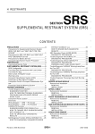
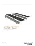
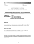
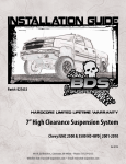
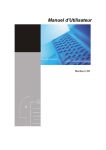
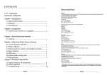
Part#: 021672
5.5” Suspension System
Chevy Colorado / GMC Canyon 4WD | 2015-16
Rev. 110615
491 W. Garfield Ave., Coldwater, MI 49036 . Phone: 517-279-2135
Web/live chat: www.bds-suspension.com . E-mail: [email protected]
Read And Understand All Instructions
And Warnings Prior To Installation Of
System And Operation Of Vehicle.
Your truck is about to be fitted with the best suspension system on the market today. That means you will be driving the
baddest looking truck in the neighborhood, and you’ll have the warranty to ensure that it stays that way for years to come.
Thank you for choosing BDS Suspension!
BEFORE YOU START
BDS Suspension Co. recommends this system be installed by a professional
technician. In addition to these instructions, professional knowledge of
disassembly/ reassembly procedures and post installation checks must be
known.
FOR YOUR SAFETY
Certain BDS Suspension products are intended to improve off-road
performance. Modifying your vehicle for off-road use may result in the
vehicle handling differently than a factory equipped vehicle. Extreme care
must be used to prevent loss of control or vehicle rollover. Failure to drive
your modified vehicle safely may result in serious injury or death. BDS
Suspension Co. does not recommend the combined use of suspension lifts,
body lifts, or other lifting devices. You should never operate your modified
vehicle under the influence of alcohol or drugs. Always drive your modified
vehicle at reduced speeds to ensure your ability to control your vehicle under
all driving conditions. Always wear your seat belt.
305/55/20 Tire
Max 5-1/4” Backspace Wheel
BEFORE INSTALLATION
• Special literature required: OE Service Manual for model/year of vehicle.
Refer to manual for proper disassembly/reassembly procedures of OE and
related components.
• Adhere to recommendations when replacement fasteners, retainers and
keepers are called out in the OE manual.
•Larger rim and tire combinations may increase leverage on suspension,
steering, and related components. When selecting combinations larger
than OE, consider the additional stress you could be inducing on the OE
and related components.
•Post suspension system vehicles may experience drive line vibrations.
Angles may require tuning, slider on shaft may require replacement, shafts
may need to be lengthened or trued, and U-joints may need to be replaced.
• Secure and properly block vehicle prior to installation of BDS Suspension
components. Always wear safety glasses when using power tools.
•If installation is to be performed without a hoist, BDS Suspension Co.
recommends rear alterations first.
• Due to payload options and initial ride height variances, the amount of lift
is a base figure. Final ride height dimensions may vary in accordance to
original vehicle attitude. Always measure the attitude prior to beginning
installation.
2 | 021672
BEFORE YOU DRIVE
Check all fasteners for proper torque. Check to ensure for adequate clearance
between all rotating, mobile, fixed, and heated members. Verify clearance
between exhaust and brake lines, fuel lines, fuel tank, floor boards and wiring
harness. Check steering gear for clearance. Test and inspect brake system.
Perform steering sweep to ensure front brake hoses have adequate slack and
do not contact any rotating, mobile or heated members. Inspect rear brake
hoses at full extension for adequate slack. Failure to perform hose check/
replacement may result in component failure. Longer replacement hoses, if
needed can be purchased from a local parts supplier.
Perform head light check and adjustment.
Re-torque all fasteners after 500 miles. Always inspect fasteners and
components during routine servicing.
021670 / 021671DRV Knuckle Box Kit
Box Kit 021673
Part #
Qty
Description
Part #
Qty
02800
1
Steering Knuckle - DRV (021670) or
02811
1
Colorado - Diff Skid Plate - BDS
2
Sway Bar Link - Colorado
Description
02801
1
Steering Knuckle - Pass (021671)
911122
401-1830
1
Tie Rod End (021670-021671)
02813
1
Colorado Bump Stop - BDS - drv
W96S
1
9/16” SAE washer (021670-021671)
02814
1
Colorado Bump Stop - BDS - pass
B1129
1
Bag Kit Sway Bar / Bump Stops
4805G8
8
Sway Bar Link Bushing
682
1
Bolt Pack (Sway Bar Links)
8
7/16” USS Flat Washer - Grade 9 - yellow zinc
Box Kit 021672
Part #
Qty
02807
1
Colorado - Front x-member - BDS
02808
1
Colorado - Rear x-member - BDS
02816
1
BDS Backing Plate - Aluminum
02809
1
02810
B1128
680
681
Description
4
7/16”-14 Nylock Nut - yellow zinc
1
Bolt Pack (Skid Plate / Bump Stop / Misc.)
Colorado - DRV Diff Drop - BDS
8
1/2"-13 x 1-1/4" Bolt - Grade 8
Colorado - Pass Diff Drop - BDS
2
1/2"-13 x 2" Bolt - Grade 8
Bag Kit - Bolt Packs
12
1/2" SAE Thru-Hardened Washer
2
1/2"-13 Prevailing Torque Nut
2
7/16" 0.281 Hole Vinyl Cushion Wire Clip
4
3/16" Cable Clamp
4
1/4"-20 x 3/4" Self Threading Bolt
2
10-24 x 3/4" Button Head Bolt - Stainless
2
#10 SAE Washer
2
10-24 Nylock Nut
95105A159
3
1/2" Rivet Nut
799
1
Bolt Pack (Rivet Nut Installation)
1
1/2"-13 x 2" Bolt - Grade 8
1
1/2" SAE Washer
1
1/2" Star Washer
1
9/16"-18 High Hex Nut
1
Bolt Pack (Colorado Cross Member)
4
5/8”-11 x 4-1/2 bolt - grade 8
8
5/8” SAE Thru-Hardened Washer
4
5/8”-11 Prevailing Torque Nut
1
Bolt Pack (Diff Drop Hardware)
3
9/16”-12 x 3-1/2” Bolt - Grade 8
6
9/16” SAE Thru-Hardened Washer
3
9/16”-12 Prevailing Torque Nut
2
14mm-2.00 x 35mm Bolt
2
683
9/16” SAE Washer - clear zinc
021674 Strut Spacer Box Kit
Part #
Qty
Description
099000
4
Zip Tie
02812
943
2
Colorado - 5.5" Strut Spacer - BDS
A246
1
Index Ring Assembly w/ Studs
1
Bolt Pack - Strut Spacers
02820
1
Colorado Index Ring
6
3/8"-16 Nylock Nut
ARP15AJ1
7
3/8"-24 Press in stud
6
3/8" SAE Washer
B1130
1
Bag Kit - Index Ring
827
1
Bolt Pack - Index Ring Kit
011406 4” Rear Box Kit
7
10mm-1.50 x 30mm FHSCS - Class 10.9
Part #
Qty
Description
7
3/8"-24 Hex Nut - Gr 8
02815
2
4" Rear Block
7
3/8" - NAS Washer
962961138QB
4
9/16" x 2-9/16" x 11-3/8" U-Bolt - Black
02821
1
Colorado Front Drive Shaft Spacer
B1131
1
Bag Kit
828
1
Bolt Pack - Drive Shaft Spacer
099000
5
Zip Ties
6
10mm-1.50 x 75mm Allen Bolt - Class 12.9
W96S-B
8
9/16" SAE Washer - black
1
Loctite
N96FH-B
8
9/16" High Nut - black
loc-tite
021672 | 3
02809 - DRV DIFF DROP (SHOWN)
02810 - PASS DIFF DROP
(2) 02812 - STRUT SPACER
02800 - DRV KNUCKLE (SHOWN)
02801 - PASS KNUCKLE
02807 - FRONT
CROSS MEMBER
02816 - BACKING PLATE
02811 DIFF SKID
02813 - DRV BUMP STOP (SHOWN)
02814 - PASS BUMP STOP
4 | 021672
02808 - REAR
CROSS MEMBER
BOX KIT
PART NUMBER
DESCRIPTION
BDS 021672
02809 -DRV
02810 - PASS
DIFF DROP BRKT
BDS 021674
(2) 02812
STRUT SPACER
BDS021673
(2)95105A159
1/2" RIVET NUT
BDS 021673
A 246
INDEX RING
BDS 021672
02807
FRONT X-MEMBER
BDS 021673
(8) 4805G
BUSHINGS
BDS 021673
02811
DIFF SKID PLATE
BDS 021672
02808
REAR X-MEMBER
BDS 021672
02816
BACKING PLATE
BDS 021673
(2) 911122
SWAY BAR LINK
BDS 021673
02813 - DRV
02814 - PASS
BUMP STOP BRACKETS
BDS 021673
02821
DRIVE SHAFT SPACER
021672 | 5
STRUT SPACER HARDWARE
(6) 3/8" NYLOCK NUTS
(6) 3/8" WASHERS
BOLT PACK # 943
X-MEMBER HARDWARE
(4) 5/8" X 4-1/2"BOLT
(4) 5/8" TORQUE NUT
(8) 5/8" WASHER
BOLT PACK #680
(2) 02812
STRUT SPACER
(2) 95105A159
1/2" RIVET NUT
(7) 3/8" FINE NUT
(7) 3/8" NAS WASH.
BOLT PACK #827
A246
INDEX RING
W/ STUDS
(7) 10 X 30mm
FLAT HEAD ALLEN
BOLT PACK #827
BACKING PLATE HARDWARE
(2)#10 X 3/4" BUTTON
(2) #10 WASHER
(2) #10 NYLOCK NUT
BOLT PACK # 683
BUMPSTOP HARDWARE
(2) 1/2" X 1-1/4 BOLT
(2) 1/2" TORQUE NUT
(4) 1/2" WASHERS
BOLT PACK #683
DIFFERENTIAL HARDWARE
(3) 9/16" X 3-1/2"
(3) 9/16" TORQUE NUTS
(6) 9/16" WASHERS
BOLT PACK # 681
DIFFERENTIAL HARDWARE
(2) 14 X 35mm BOLT
(2) 14mm WASHER
BOLT PACK #681
(6) FACTORY
HARDWARE
02809 - DIFF DROP (DRV)
02810 - DIFF DROP (PASS)
(2) 911122
SWAY BAR LINK
(8) 4805G
BUSHING
(4) 7/16" NYLOCK NUT
(8) 7/16" WASHER
BOLT PACK # 682
02813 - BUMP STOP (DRV)
02814 - BUMP STOP (PASS)
6 | 021672
BUMPSTOP HARDWARE
(2) 1/2" X 2 BOLT
(2) 1/2" WASHER
BOLT PACK # 683
(6) 10 X 75MM BOLT
(BOLT PACK # 828)
02821
DRIVE SHAFT
SPACER
(6) 1/2" X 1-1/4" BOLTS & WASHERS
SKID PLATE HARDWARE
BOLT PACK #683
TROUBLESHOOTING INFORMATION FOR YOUR VEHICLE
1.
If using a plasma cutter for frame bracket modification, disconnecting the battery is highly
recommended.
2.
Stock 17” & 18” wheels can not be reinstalled with the lift kit. Aftermarket 20” wheels with maximum
of 5.25” Backspacing are recommended - certain wheel and tire combinations will require weld on
steering stops, these are included in the kit. See end of inst. sheet for details on installation.
3.
6 cylinder models require slight exhaust modification. 4 cylinder / Diesel models could possibly
require exhaust modification
4.
Rack and Pinion steering is sensitive to tire choice. Tires with large lugs, little backspacing, or extreme amounts of weight may
induce a steering wheel bobble.
INSTALLATION INSTRUCTIONS
1.
Park vehicle on clean, flat, and level surface. Block the rear wheels
for safety, chock both the front and backside of the tires. Put the
transmission in Neutral (required for index ring installation)
36mm Socket, Air Hammer / Chisel highly recommended
Plasma Cutter or other cutting device (sawzall or cutoff wheel)
2.
Disconnect the battery.
3.
Raise the front of the vehicle and support the frame rails with jackstands.
4.
If a plasma cutter is to be used for frame bracket modification (later in installation), it is recommended to disconnect the battery at this
time.
5.
Remove the front wheels
DISASSEMBLY INSTRUCTIONS
6.
Remove any differential skid plates (if equipped) and the front splash shield from the vehicle. None of the factory skid plates will be
reinstalled.
7.
Remove the clip from the brake line to allow the brake line to detach from the bolt on brake line bracket.
8.
Remove the brake bracket from the side of the upper strut mount, discard flanged bolt. (Fig 1). Remove the bracket from the vehicle by
cutting a slot in the bracket for clearance to the brake line. Discard bracket, it will not be reused.
FIG 1
021672 | 7
9.
Disconnect the brake caliper from the steering knuckle, retain mounting bolts. Hang the caliper out of the way; do NOT allow the caliper to
hang from the brake line. (Fig 2)
FIG 2
10. Remove the torx head bolt (T30) that attaches the rotor to the hub. Keep bolt for reinstallation. (Fig 3)
FIG 3
11. Disconnect the ABS wire from the backside of the steering knuckle, remove the clip and retain the bolt. (Fig 4)
FIG 4
8 | 021672
12. Remove the ABS sensor from the side of the knuckle (T30), retain mounting bolt. (Fig 5)
FIG 5
13. Remove the CV nut. CV’s have a tight fit to the hubs, it may be necessary to use an air hammer to separate them. Reinstall the nut a few
turns to keep from damaging the CV shaft if this method is used. (Fig 6)
FIG 6
14. Remove the factory sway bar links, they will not be reused.
15. Break the jam nuts loose on the tie rod ends at this time. The factory tie rod ends will be replaced later in the installation.
16. Remove the ball joint nuts and tie rod end nuts. Use an appropriate tool to unseat the tapers from the factory knuckle. It is NOT
recommended to use a hammer to separate the joints if the knuckles are ever planned to be reused. (Fig 7, 8)
021672 | 9
FIG 7
FIG 8
17. Remove the knuckle and hub assembly from the vehicle.
18. Remove the lower control arms. Retain the cam bolts / washers. (Fig 9, 10)
FIG 9
FIG 10
19. Remove the factory struts. Remove the lower bolt that attaches to the control arm and the 3 nuts that attach the strut to the upper strut
mount. Do NOT remove the center nut that holds the strut assembly together.
DIFFERENTIAL REMOVAL
20. Disconnect the differential breather hose from the differential and the central axle disconnect wiring harness (Fig 11, 12)
The differential breather line is tough to access, wait until the differential is lowered a slight amount to pull the hose
off if necessary.
10 | 021672
FIG 11
FIG 12
21. Disconnect the front drive shaft from the differential. Discard front mounting hardware, it will not be reused) (Fig 13). Disconnect the front
driveshaft from the transfer case, SAVE hardware, it will be reused. Remove the front driveshaft from the vehicle.
FIG 13
22. Remove the rear differential mounting bolt (Fig 14). Remove the rear factory cross member (Fig 15), Discard hardware, it will not be reused.
FIG 14
FIG 15
021672 | 11
23. Support the differential with a hydraulic jack (transmission jack preferred). Remove the remaining two front mounting bolts and lower the
differential from the vehicle. (Fig 16)
FIG 16
FRAME MODIFICATION
24. The front factory lower control arm pocket will need to be modified to allow the new crossmember to be installed.
FRONT POCKET MODIFICATION
25. Measure down 1-1/8” from the BOTTOM of the factory slot on both the front and back sides and make a horizontal mark. Connect these
two lines by measuring ‘in’ towards the center of the vehicle 1-1/8” and making a line that goes from front to back. Remove this section of
material from the vehicle. Use a grinder to make the faces flush and remove any sharp edges so that the cross member can be installed
easily. Coat with paint. (Fig 17a, 17b, 17c, & 17d)
Due to the factory forming of the front pocket, it can be difficult to install the front crossmember. Use a hammer or
adjustable wrench to unflair the factory pocket if necessary.
12 | 021672
FIG 17A
FIG17B
FIG 17C
FIG 17D
PASSENGER’S REAR POCKET MODIFICATION
26. Draw a line that connects the top of the outside slot and bottom of the inside slot and remove the material from vehicle. Use a grinder to
remove sharp edges, coat with paint when completed. (Fig 18a, 18b)
FIG 18A
FIG 18B
021672 | 13
DRIVER’S REAR POCKET MODIFICATION
27. Draw a horizontal line from the top of the outside slot.
28. Draw a vertical line from the center of the outside slot
29. Draw a line that would go through the center of the stock alignment pin that is perpendicular (about 45 degrees from horizontal) to the
inside face.
30. Remove this section of material from the vehicle, remove any sharp edge with a grinder, and coat with paint. (Fig 19a, 19b, 19c, & 19d)
FIG 19A FIG 19B
FIG 19C
FIG 19D
CROSSMEMBER / DIFFERENTIAL INSTALLATION
31. Install the new front crossmember with new 5/8”x 4-1/2” hardware (BP #680). Run the bolts from front to rear, Do NOT put the nuts on the
bolts at this time. Crossmember are a tight fit if not enough material was removed during the frame pocket modification. (Fig 20)
14 | 021672
FIG 20
32. Install the new differential drop brackets (02809 – DRV, 02810 – PASS) with new 14mm x 30mm bolts and washers (BP #681) to the frame.
Brackets will attach to the front cross member hardware, attach with 5/8” nuts and washers. Push the differential brackets all the way
towards the front of the vehicle and tighten 14mm hardware to 95 ft-lbs. Leave 5/8” hardware loose. (Fig 21)
FIG 21
33. Install differential to the new drop brackets with 9/16” x 3-1/2” hardware (BP #681). (Fig 22a, 22b)
FIG 22A
22B
021672 | 15
34. Raise the rear differential mount. Install rear cross member with new 5/8” x 4-1/2” hardware (BP #680). Attach differential to rear
crossmember with new 9/16” x 3-1/2” hardware (BP#681). (Fig 23)
FIG 23
35. Reconnect the differential breather line and the central axle disconnect wiring harness.
BUMP STOP INSTALLATION
36. Remove the factory bump stops, use a hammer and a punch to get the bump stops to pop out of the factory cup. (Fig 24)
FIG 24
37. Clearance the hole inside the bump stop cup to 11/16”, a step drill is highly recommended, if one is not available, a rotary die grinder can be
used. Insert and seat ½” rivet nut. Follow rivet nut installation at the end of the instruction sheet. (Fig 25)
See the end of the instruction sheet for how to install 1/2” rivet nuts. There is one extra rivet nut provided in the kit
incase one is installed incorrectly. If both are installed correctly, there will be an extra rivet nut at the end of the installation.
16 | 021672
FIG 25
38. Attach the new bump stop extension (02813 – DRV, 02814 – PASS) to the rivet nut with ½” x 2” hardware (use socket and extension to
attach) and to the cross member with ½” x 1-1/4” bolt, washers, and nut. (BP #683) (Fig 26)
FIG 26
39. Install lower control arms with factory cam bolts and nuts. It is recommended to run the front bolts from Rear to Front, and the rear bolts
from Front to Rear so that the nuts are easily accessible. They must be torqued to 170 ft-lbs later in the installation. Snug, but do not
tighten at this time.
40. Go back and tighten 5/8”” Differential / Crossmember hardware to 120 ft-lbs., 9/16” differential hardware to 90 ft-lbs., Tighten ½” bump stop
hardware to 65 ft-lbs.
41. Install the factory bump stops into the replacement bump stop brackets. Lube the bump stop with a small amount of grease, use a jack on
the lower control arm to press the bump stops into the cup. (Fig 27)
021672 | 17
FIG 27
STRUT MODIFICATION OR OPTIONAL COILOVER INSTALLATION
42. Locate the upper strut spacers (02812). Attach the strut spacers to the stock struts with factory hardware. Tighten to 40 ft-lbs. (Fig 28a,
28b) Note: Use a 3/8” chrome 18mm socket with a 3/8” swivel to tighten the nut inside the strut spacer.
FIG 28A
FIG 28B
43. Install the strut and spacer into the vehicle. Attach the strut to the upper mount with new 3/8” nylock nuts and washers (BP #943). Attach
lower mount to the lower control arm with factory bolts. Tighten the 3/8” hardware to 35 ft-lbs, do NOT tighten the lower mount at this
time. It will be done at the end of the installation with the vehicle weight on the ground. (Fig 29a, 29b)
18 | 021672
FIG 29A
FIG 29B
44. Optional: Install coilover assembly so that the hose is to the rear of the vehicle and loops below the upper control arm. Attach reservoir
bracket and upper mount with included hardware. Use factory lower hardware to attach the bottom. Tighten upper hardware to 40 ft-lbs,
lower hardware to 95 ft-lbs. Attach reservoir to the bracket with included hose clamps. Cycle the upper control arm to ensure there will be
clearance between the hose at full droop and clearance to the reservoir under compression.
KNUCKLE ASSEMBLY
45. Remove the factory hub and dust shield from the stock knuckles. Transfer them over to the new steering knuckle. Note: You MUST install
the dust shield, failure to do so will cause ABS problems. (Fig 30)
FIG 30
46. Apply loctite to the factory hub bolts, and tighten hub hardware to 133 ft-lbs.
47. Install grease zerk into new tie rod ends. Install the new tie rod ends onto the factory inner tie rods.
021672 | 19
48. Install new steering knuckle assembly to the lower control arm and run the CV shaft through the hub. Attach upper ball joint and new tie
rod end to knuckle assembly, use the included washer under the nut for the tie rod end. Use stock hardware Tighten lower ball joint to 92
ft-lbs, upper ball joint to 70 ft-lbs, tie rod end to 44 ft-lbs, and CV nut to 177 ft-lbs.
49. Reinstall the brake rotors with the torx bit holding the rotor to the hub assembly.
50. Reinstall the brake calipers with factory hardware. Tighten to 148 ft-lbs.
51. Clean any debris from the ABS sensors. Install the ABS sensors into the steering knuckle with factory hardware. Tighten to 11 ft-lbs. (Fig
31a)
52. Attach the ABS sensor wire to the back of the steering knuckle with a new cable clamp (BP #683) and factory hardware. The grommet on
the ABS wire can be slid by spraying it with silicone spray. Ensure there is adequate slack through wheel travel and full steering range of
motion, ensure the ABS wire can not rub on the CV shaft. (Fig 31b)
FIG 31A
FIG 31B
53. Install new sway bar links (911122) with (8) washers and (8) bushings (4805G) as shown. Attach with (4) 7/16” nylock nuts (BP #682). (Fig
32) Tighten until the bushings begin to swell, do NOT over tighten the hardware.
20 | 021672
FIG 32
BRAKE LINE / ABS WIRE MODIFICATION
54. Carefully form the brake line to allow the mounting end to attach to the side of the bump stop cup. Reinstall the factory retaining clip to
hold the brake line in place.
55. Reform the hard line slightly to create clearance from any sharp edges. Attach brake line to the side of the frame rail and the factory bump
stop bracket by drilling 7/32” holes and using 3/16” cable clamps with ¼” self threading bolts (BP #683). (Fig 33)
FIG 33
56. Zip tie the ABS wires to the brakeline to allow adequate slack through wheel travel and turning motions.
INDEX RING INSTALLATION:
57. Note: The front driveshaft should be completely removed at this point, if it is not, remove and retain hardware, remove driveshaft from the
vehicle.
58. Disconnect the U-joint hardware, remove straps, and disconnect rear drive shaft from the rear axle, remove rear driveshaft. (Fig 35).
021672 | 21
FIG 35
59. Remove the differential skid plate if equipped (3 bolts), it will not be reinstalled. (Fig 36)
FIG 36
60. Disconnect the transfer case shift mechanism wiring harness, disconnect wiring harness clips from transfer case. (Fig 37a)
FIG 37A
61. Disconnect the breather from on top of the transfer case, above the front driveshaft output. (Fig 37b)
22 | 021672
FIG 37B
62. Support the transmission with a transmission jack, use extra care not to damage any surfaces on the transmission. Remove the factory
transmission crossmember, remove the transmission mount, retain all hardware. (Fig 38a, 38b)
FIG 38A
FIG 38B
63. Support the transfer case. Remove the 7 nuts that hold the transfercase to the transmission and remove the transfer case from the vehicle.
64. Remove the 7 studs from the transfer case. Double nut the factory nuts in order to remove them. (Fig 40)
FIG 39
021672 | 23
65. Install new index ring assembly with loctite on the new 10mm Flat Head Allen Bolts (BP #827), leave the factory gasket on the transfer case.
Tighten to 35 ft-lbs (Fig 40a).
The indexing ring has a specific orientation, it will only go on one way, rotate until all of the holes align.
66. Reinstall transfer case with new indexing ring with new 3/8” washers and nuts, with loctite on the threads (BP #827). Tighten to 45 ft-lbs.
(Fig 40b)
FIG 40A
FIG 40B
67. Reinstall transmission mount and crossmember with factory hardware, reattach wiring harness, and transfer case breather. Reinstall the
rear driveshaft with factory straps and hardware. Tighten all hardware to factory specifications
68. The front crossover exhaust pipe will be close to the front driveshaft when installed. Loosely fit the front driveshaft and mark the area just
below the driveshaft on the crossover pipe. Squish in the top part of the exhaust tube approximately 1/4” to create clearance when the
driveshaft is installed. Use a clamp with support on the bottom side, or use a torch to heat the area and dent in with a hammer (Fig 41a).
When the front driveshaft is installed there will be approximately a 1/4” gap, this is not enough clearance when in 4wd
and the crossover pipe must be modified.
69. Reinstall the front driveshaft. Use factory hardware with loc-tite at the transfer case output. Attach driveshaft to the front differential with
new 10mm bolts (BP #828) with loc-tite and driveshaft spacer (#02821). Torque to 45 ft-lbs. (Fig 41b)
FIG 41A
FIG 41B
FINAL FRONT STEPS:
24 | 021672
70. Recheck differential hardware for proper torque. Install skid plate (02811) with ½” x 1-1/4” bolts with washers (BP #683) Tighten to 65 ft-lbs.
71. Attach the backing plate to the backside of the front cross member with #10 stainless hardware (BP #683).
72. Recheck all front hardware for proper torque, cycle steering to check for adequate clearances.
73. Reinstall front wheels. Tighten to factory specifications.
74. Lower vehicle to the ground. Adjust Cams as shown (Fig 42a - front, Fig 42b - rear), Tighten Cam hardware to 170 ft-lbs. Tighten lower strut
hardware to 95 ft-lbs.
This is not the final alignment, but a good start for driving to an alignment shop. Adjust the toe-in to approximately
1/8” in, and straighten the steering wheel. Do NOT drive the vehicle with the steering wheel off-center.
FIG 42A (FRONT)
FIG 42B (REAR)
REAR INSTALLATION
75. Block the front wheels for safety. Raise the rear of the vehicle and support frame rails with jackstands.
76. Remove the stock wheels and tires.
77. Disconnect the ABS wire from the clip on the side of the frame rail, this will allow extra slack in the ABS line. (Fig 43)
FIG 43
78. Remove the e-brake cable guide bracket from the side of the frame rail on the driver’s side. It will not be reinstalled.
79. Form the stock brake line upper bracket ‘down’ to gain adequate slack. Use an adjustable wrench to form the stock brake line bracket
down. (Fig 44a, 44b)
021672 | 25
FIG 44A
FIG 44B
80. Working on one side of the vehicle at a time. Support the axle with a hydraulic jack, remove the factory u-bolts. Remove the stock shocks,
retain hardware.
81. Lower the axle and install new lift block. Install new u-bolts with nuts and washers. Snug but do not tighten at this time. (Fig 45a, 45b)
FIG 45A
FIG 45B
82. Repeat block installation on opposite side of vehicle.
83. Grease and install new bushings and sleeves into shocks. Install the shocks with factory hardware. Tighten to 55 ft-lbs.
84. Lower the axle and check for adequate slack in the brake lines and abs wire, adjust as necessary.
85. Slide the grommet on the ABS wire on the passenger’s side by the exhaust up (use silicone spray to allow the grommet to slide easily). Slide
the ABS wire heat shield tubing up and secure with a zip tie. (Fig 46a)
86. Attach the ABS wire to the u-bolt with included zip tie (Fig 46b), repeat on opposite side.
26 | 021672
FIG 46A
FIG 46B
87. Use two zip ties, secure the e-brake cables together in front of where the old e-brake cable guide bracket contacted the cables. (Fig 47)
FIG 47
88. Install wheels, tighten lug nuts to factory specifications.
89. Lower the vehicle to the ground and torque u-bolts to 110 ft-lbs.
90. Reconnect the battery.
91. Recheck all hardware for proper torque. Check again after 500 miles.
92. A front end alignment is now required. Ensure the lower cam bolts are torqued to 170 ft-lbs after alignment.
OPTIONAL WELD ON STEERING STOPS:
93. Included are optional weld on steering stops. These can be welded to the lower control arm to reduce rubbing or eliminate any
interference issues that my be present at full steering lock. Disconnect the batter, prep lower control arm for welding, weld steering stop
onto the lower control arm as shown. Coat with paint when completed. (Fig 48a, 48b)
021672 | 27
FIG 48A
FIG 48B
OPTIONAL FRONT FENDERWELL MODIFICATION FOR TIRE CLEARANCE:
94. Remove the 4 lower T-15 Torx head bolts that hold the fenderwell to the plastic support piece. (Fig 49a, 49b)
FIG 49A
FIG 49B
95. Trim back to the first full support rib. Remove this section from the support piece. (Fig 50a, 50b)
A sawzall works well for trimming the factory plastic. A box cutter style knife with the blade heated by a MAP gas /
propane torch cuts the factory plastic bumper cover nicely and leaves a good smooth finish.
28 | 021672
FIG 50A
FIG 50B
96. Remove the nut clips from the trimmed piece. Hold the inner fenderwell up to the front support piece and drill new holes for the mounting
hardware at a convenient location. Attach the inner fender to the plastic support piece with factory torx bit hardware. Trim a slight amount
on the plastic bumper cover for additional clearance if required. (Fig 51a, 51b)
FIG 51A
FIG51B
RIVET NUT INSTALLATION INSTRUCTIONS
RIVET NUT SIZING
1.
Verify the correct size rivet nut for the application based on the thickness of material where the rivet nut is to be installed using the
following chart.
Part
Thread
Body
Material Thickness
Drill
Number
Size
Length (in)
(in)
Size (in)
Min.
Max.
95105A159
3/8-16
.690
.027
.150
17/32
95105A168
3/8-16
.805
.150
.312
17/32
95105A169
1/2-13
1.150
.063
.200
11/16
95105A170
1/2-13
1.300
.200
.350
11/16
021672 | 29
HOLE PREPARATION
2.
Drill hole to appropriate size for rivet nut installation. 1/2” Rivnuts require an 11/16” hole and 3/8” Rivnuts require a 17/32” drill. It is critical
that this hole is drilled to the correct size. Remove any burrs that could keep the rivet nut from seating flat against either side of the hole
surface.
If the correct drill size is not available, it is possible to drill the hole to an available smaller size and slowly grind it out
to until the rivet nut fits tight.
RIVET NUT INSTALLATION TOOL ASSEMBLY
3.
For a 3/8” rivet nut, place the provided 3/8” SAE flat washer on the 3/8” x 1-1/2” bolt, followed by 7/16” hex nut and then a 3/8” serrated
washer. (Fig. 1) Thread this tool assembly into the rivet nut.
4.
For a 1/2” rivet nut, place the provided 1/2” SAE washer on a 1/2” x 2” bolt followed by a 9/16” high nut and 1/2” serrated edge lock washer.
Thread this tool assembly into the rivet nut as shown. (Fig. 1)
FIGURE 1- 1/2” RIVET NUT SHOWN
.
RIVET NUT INSTALLATION
5.
Place the installation tool with the rivet nut threaded on the end into the appropriately sized hole.
6.
For a 3/8” rivet nut, hold the nut closest to the rivet nut still with an 5/8” wrench and tighten the 3/8” bolt with a 9/16 wrench to set the rivet
nut. Be sure to hold the rivet nut flush to the surface and square to the hole as it is tightened. (Fig. 2)
If available, an impact gun is recommended for tightening the bolt to ensure the rivet nut remains square to the hole
and to ease holding the nut from spinning.
7.
For a 1/2” rivet nut, hold the nut closest to the rivet nut still with an 7/8” wrench and tighten the 1/2” bolt with a 3/4” wrench to set the rivet
nut. Be sure to hold the rivet nut flush to the surface and square to the hole as it is tightened. (Fig. 2)
FIGURE 2 - 1/2” RIVET NUT SHOWN
30 | 021672
TORQUE SPECIFICATIONS
8.
3/8” rivet nuts will approach 40 ft. lbs for maximum grip strength. Do not exceed 45 ft-lbs when setting the rivet nut.
9.
1/2” rivet nuts will approach 90 ft lbs for maximum grip strength. Do not exceed 100 ft-lbs when setting the rivet nut.
Note: If using the recommended impact gun, use caution to not exceed the recommended torque specifications.
RIVET NUT TOOL REMOVAL
10. Once the center bolt is tightened, remain holding the nut from spinning with the wrench and loosen the center bolt to remove the
installation tool.
It is very important to hold the nut as the bolt is loosened because the grip of the star washer will try to spin the
rivet nut and ruin the installation.
11. Verify proper installation by checking for consistent rivet nut deformation to see the threads are square and centered to the rivet nut.
(Fig. 3)
FIGURE 3
Thank you for choosing BDS Suspension.
For questions, technical support and warranty issues relating to this BDS Suspension product, please contact your distributor/installer
before contacting BDS Suspension directly.
021672 | 31