1
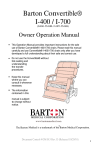
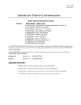
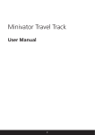
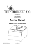
www.bartonmedical.com
5725 Hwy 290 West, Suite 103
Austin, TX 78735
Tel: 512-476-7199
Ceiling Track Lift
Service Manual
RTB-400-70
RTB-415-70
RTB-600-70
RTB-615-70
RTB-1015-70
SM 003
Revision: C
Revision Date: 6/24/2008
TABLE OF CONTENTS
PREPARATION
3
SECTION 1:
REMOVE MOTOR FROM THE TRACK.
4
SECTION 2:
REMOVE PLASTIC COVER
5
SECTION 3:
REPLACE BATTERY.
6
SECTION 4:
REPLACE O-RING.
7
SECTION 5:
REMOVE CARRY BAR.
8
SECTION 6:
REPLACE STRAP.
9
SECTION 7:
REPLACE CONTROL BOARD
SECTION 8:
REPLACE LIMIT SWITCH
12
SECTION 9:
REPLACE MEMBRANE SWITCH
13
SECTION 10:
REPLACE EMERGENCY SWITCH
14
SECTION 11:
INSTALL EMERGENCY PULL CORD
15
SECTION 12:
INSTALL TRAVERSE CHAIN
16
SECTION 13:
REPLACE TROLLEY WHEELS
17
APPENDIX A
PREVENTATIVE MAINTENANCE
18 - 20
APPENDEX B
TROUBLE SHOOTING STEPS
21 - 28
APPENDEX C
PARTS LIST
10 - 11
29
PREPARATION
Cleaning & Disinfecting
WARNING
Gloves and protective clothing should always be worn when carrying out cleaning procedures.
All surfaces can be cleaned by wiping with a disposable cloth moistened with hand hot water and a
neutral detergent. Rinse using clean water, dry with paper towels.
When used by a patient known or suspected of having an infection this piece of equipment should be
disinfected. After washing, wipe over with NaDCC at 1,000 ppm of available chlorine (or other chlorine releasing agent). Alternatively wipe over with a 70% Isopropyl Alcohol wipe.
CAUTIONS
DO NOT use Hypocarbonate or Phenol based cleaning agents
DO NOT use any volatile liquids such as thinners or petroleum
DO NOT use abrasive compounds or pads.
Tests show undiluted Dettol may damage paint and plastic parts if prolong contact is allowed.
Recommended Tools
Below is a list of tools required to carry out the service procedures contained in this manual:
Adjustable Wrench
Socket Set 7/16” and 9/16” with extension
Adjustable Torque Wrench – Adjustable up to 40ft/lbs
Screw Driver Set (W/ Multiple Bits)
Multi-meter (0-50VDC)
Step Stool or ladder
Gloves
Needle nosed pliers
Metric Allen wrench set
Flashlight
C-clip removal tool
Punch
Hammer
WARNING
All tools can be dangerous if used incorrectly.
3
REVISION DATE 6/24/2008
SM003
REVISION C
CAUTION
DO NOT attempt to perform service on the ceiling lift without proper training and understanding of this
document. Failure to adhere to this warning may result in serious injury to the operator, and/or the individual being lifted /transferred
SECTION 1: TO REMOVE MOTOR FROM TRACK. : Unplug the charger from electrical source
before perform this task.
4. Safety Pin
5. Safety Pin Ring
6. End Stop Plate
7. End Stop Bolts
1. Charger Connector
2. Charger End Plate
3. Charger End Screw
1.1 Remove ring
1.5 Remove charger connector
1.2 Remove pin
1.3 Remove screw
1.7 Remove end stopblock and plate
1.6 Loosen end stop
bolts
1.4 Remove end plate
1.8 Remove motor
CAUTION
A sturdy ladder is required in order to access the underside of the lift to remove the motor from the track.
Motor and carry bar is a heavy object. Use caution when perform this task.
4
REVISION DATE 6/24/2008
SM003
REVISION C
SECTION 2. TO REMOVE PLASTIC COVER: Move carry bar down to the lowest position before
performing this procedure.
1. Hand Control Connector
2. Strap
3. Emergency Cord
4. Housing Screws
5. Top Housing
6. Bottom Housing
4
5
6
1
2
3
2.3 Remove housing screws (4)
2.1 Remove hand controls crew
2.2 Remove hand controller
2.4 Turn unit over to remove Bottom Cover
2.5 Remove all electrical connectors and remove the bottom cover.
NOTE: This step is not necessary in most case. Refer to the specification section to
determine if this step is required or not.
1
2
3
4
1. Up/Down connector
2. LEDs Display connector
3. Emergency Pull Cord connector
4. Power/ Emergency Down connector
5
REVISION DATE 6/24/2008
SM003
REVISION C
SECTION 3: TO REPLACE BATTERY
1. Battery
2. Bracket
3. Securing Nuts
3.1 Remove bottom cover per instructions
in section 2.1-2.4 DO NOT disconnect
cables attached to the bottom cover
3.2 Remove one nut
3.3 Loosen other nut and rotate
the bracket 90 degree
3.4 Remove battery and flip it
over
3.7 Repeat step 3.2 - 3.6 for
the other battery
3.5 Transfer the terminal from old battery
to the new battery as followings:
BLUE: - NEGATIVE terminal (BLACK)
RED - POSITIVE terminal (RED)
3.6 Flip battery and fasten both
nuts.
6
REVISION DATE 6/24/2008
SM003
REVISION C
SECTION 4: TO REPLACE O-RINGS
Notes:
Before handling replacement O-ring, be sure your hands are free of grease or oil.
It is recommended O-rings be replaced every 6 months
O-ring (00-500-199 Ø.739 x .070) for
Upper Limit Switch
O-ring (00-500-463 Ø.801 x .070) for
Lower Limit Switch
4.1 Remove bottom cover per instructions in section 2.1-2.4
DO NOT disconnect cables attached to the bottom cover
4.2 Remove old O-rings and replace with new ones as shown
above
NOTES:
O-RINGS FOR THE LOWER LIMIT SWITCHES ARE SLIGHTLY LARGER THAN THE ONES
FOR THE UPPER LIMIT SWITCHES
CAUTION:
Check the tightness of each O-ring after installation to ensure the proper size O-ring has been used.
Installation of wrong size O-rings could cause serious malfunction of the lift and potentially cause injury.
7
REVISION DATE 6/24/2008
SM003
REVISION C
SECTION 5: TO REMOVE CARRY BAR
Carry Bar for all models
except RTB 1015-70
5.3 Push center HUB down
5.1 Remove C-Clip
5.2 Remove cover
5.4 Remove center dowel pin
5.5 Remove strap
Carry Bar for RTB 1015-70
5.5 Remove securing nuts
and pin to remove carry bar
8
REVISION DATE 6/24/2008
SM003
REVISION C
SECTION 6: TO REPLACE STRAP
6.1 Remove motor from track per SECTION 1. Using the handset, unwind the belt to its full length.
6.2 Remove Bottom Cover per SECTION 2
6.3 Remove Carry Bar per SECTION 5
6.4 Remove all 4 screws and
bridges to remove pin
6.5 Slide pin away from shaft
6.6 Pull center pin out
6.7 Remove strap by pulling
it away from the wheel
6.8 Remove bottom plate by
removing 8 screws (4 on each
side)
6.9 Remove both O-rings for
the upper limit switch pin and
pull out pin and roller.
6.10 Removing strap and replace with new strap
6.11 Follow steps 6.1 through 6.9 in reverse order to put strap back in. Ensure to engage the
emergency break before placing the spool back into the assembly.
9
REVISION DATE 6/24/2008
SM003
REVISION C
SECTION 7: TO REPLACE CONTROL BOARD
CAUTION:
ESD (electrostatic discharge) protection is required before handling the control board to prevent damage
to sensitive devices
7.1 Remove motor from the track per SECTION 1.
7.2 Remove Bottom Cover per SECTION 2. Disconnect all cables to cover. Disconnect the cable to the
battery per SECTION 3.5
7.3 Remove Bottom Plate per SECTION 6.8
7.4 Remove upper limit switch roller per SECTION 6.9
7.5 Remove 4 control board
screws
7.6 Remove control board
and remove all connectors
7.7 Hand Control connector
(Connector #1 - 4 pins)
7.8 Traversing Motor
(Connector #2 - 4 pins)
7.9 Hand Control connector
(Connector #3 - 6 pins)
7.12 Membrane Switches
(Connector #6 - 6 pins)
7.10 Hour Meter
(Connector #4 - 2 pins)
7.11 Limit Switches
(Connector #5 - 3 pins)
7.13 Main Housing LEDs
(Connector #7 - 5 pins)
10
REVISION DATE 6/24/2008
SM003
REVISION C
SECTION 7: TO REPLACE CONTROL BOARD (Continued)
7.14 Main Motor
(Connector #8 - 4 pins)
7.16 Fasten control board to
the chassis with 4 screws
7.15 Charger Connector
(Connector #9 - 2 pins)
7.17 Reinstall the upper limit
switch roller and O-ring
7.18 Reinstall bottom plate
with 8 screws (4 on each side)
7.20 Follow step 2.1 through
2.3 in reverse order to fasten
cover.
7.19 Re-connect the cables to
the bottom cover
11
REVISION DATE 6/24/2008
SM003
REVISION C
SECTION 8: TO REPLACE LIMIT SWITCH
CAUTION
ESD (electrostatic discharge) protection is required before handle the control board to help prevent damage to sensitive devices
LOWER LIMIT SWITCH
UPPER LIMIT SWITCH
8.1 Remove motor from the track per SECTION 1.
8.2 Remove Bottom Cover per SECTION 2. Disconnect all cables to cover. Disconnect the cable to the
battery per SECTION 3.5
8.3 Remove screws (2) that fasten the limit switch to the chassis
8.4 Install the new switch and fasten the screws to secure the switch
8.5
12
REVISION DATE 6/24/2008
SM003
REVISION C
SECTION 9: TO REPLACE MEMBRANE SWITCH
9.1 Remove motor from the track per SECTION 1.
9.2 Remove Bottom Cover per SECTION 2 (disconnect all cables to cover)
POWER / EMERGENCY
DOWN SWITCH
UP / DOWN MEMBRANE
SWITCH
9.3 Remove the desire switch by peeling away from cover.
9.4 Install new switch by peeling the back adhesive away and place the switch in the original location
9.5 Re-connect all of the Cables per diagram below
9.6 Follow steps 2.1 through 2.4 in reverse order to put bottom cover back in.
1
2
3
4
1. Up/Down connector
2. LEDs Display connector
3. Emergency Pull Cord connector
4. Power/ Emergency Down connector
13
REVISION DATE 6/24/2008
SM003
REVISION C
SECTION 10: TO REPLACE EMERGENCY STOP SWITCH
10.1 Remove motor from the track per SECTION 1.
10.2 Remove Bottom Cover per SECTION 2 (disconnect all cables to cover)
10.4 Remove the fastener on the switch
10.3 Remove the knob by loosen knot at the
end.
10.5 Remove the switch from the other side by
rotating the switch counter clockwise.
10.5 Replacing the switch and reverse steps
10.1 to 10.5 to install new part
14
REVISION DATE 6/24/2008
SM003
REVISION C
SECTION 11: INSTALL EMERGENCY PULL CORD
BEFORE
AFTER
11.1 Remove existing hardware
11.2 Install the emergency pull cord ball chain connector to the ball chain on the
switch. Use pliers to crimp the two parts together.
15
REVISION DATE 6/24/2008
SM003
REVISION C
SECTION 12: TO REPLACE TRAVERSE CHAIN
12.1 Perform step 6.1 to 6.6 (SECTION 6 - REPLACE STRAP)
12.2 Drop the chain on top of the traverse gear through the top housing
12.2 Assemble the chain to a complete loop
12.3 Flip the unit over to remove the traverse wheel on the
trolley. Ensure that the chain does not fall through the housing
by putting tape on it. Remove the wheel and bearing on one
side of the trolley and pull the assembly away
12.4 Install the chain over the Trolley wheel and ensure full
engagement. Reinstall the trolley wheels and bearing
10.5 Following step 6.1 to 6.6 in reverse to put
unit back together
16
REVISION DATE 6/24/2008
SM003
REVISION C
SECTION 13: TO REPLACE TROLLEY WHEELS
13.1 Remove motor from track per SECTION 1
13.2 Remove the screw
13.3 Remove the wheel
13.4 Remove the washer
and bearing
13.5 Remove the bearing
and shaft
13.6 Install new bearings
and shaft
13.7 Install washers(2)
washer and bearing
13.8 Install new wheels and fasten the screws.
Ensure to apply locktite to the screws before the
installation.
17
REVISION DATE 6/24/2008
SM003
REVISION C
APPENDIX A: PREVENTATIVE MAINTENANCE - CONTINUED
A1 - CHECK LIST PRIOR TO EACH USAGE
•
Check lift strap, make sure there is no fraying (See SECTION 6 for Service Instructions)
•
Check all Strap stitching (See SECTION 6 for Service Instructions)
•
Visual inspect to ensure ther is no damage to lift or carry bar
•
Listen to ensure that lift is not making any unusual sounds when in use
•
Be sure that all end stops are installed and secured at every track end
•
Visual inspect to ensure that the lift is getting charged from charger - Amber light
should come on while in Charging posion.
•
Visual inspect to ensure that all end stops are installed and secured at every track end
18
REVISION DATE 6/24/2008
SM003
REVISION C
APPENDIX A: PREVENTATIVE MAINTENANCE - CONTINUED
A2 - CHECK LIST FOR QUARTERLY MAINTENANCE
•
•
Complete the entire visual inspection in Section A.1
Check that all brackets holding track are secured and do not move
•
•
•
Check that all bracket bolts are tightened to 5 ft/lb
Check that all endstops bolts are tightened to 25 ft/lb (two bolts per end stop)
The lift should move freely and traverse entire length of track system
•
All O-rings (4) should be inspected and replaced if there are any signs of brittleness or stretching.
It is recommended to change O-rings every 6 months regardless of their condition. O-rings are subject to
ambient air condition, temperature, frequency of use, etc. ; all of which may affect life expectancy. Indicators of O-ring issues are:
•
If slackening of belt does not immediately engage lower limit switch
•
If fully wound belt does not immediately engage upper limit switch. (Refer SECTION 8)
CHECK FUNCTION UPPER LIMIT SWITCH
•
Using the handset, check the function of the Upper Limit Switch (Refer to SECTION 8) by winding in the belt fully, thereby activating the Upper Limit Switch. If the switch does not shut down the unit,
change both O-rings and repeat this procedure. In the event the switch still does not activate, the metal arm
of the switch can be adjusted slightly in order to make better contact with the roller. To adjust: bend the
metal arm out slightly using a pair of needle -nose pliers. (Refer to SECTION 8)
CHECK FUNCTION LOWER LIMIT SWITCH
•
Check the function of the Lower Limit Switch (Refer to SECTION 8) by using the down button on
the hand control to unwind the belt. While the belt is unwinding under weight of the CARRY BAR, grab
the CARRY BAR with your free hand allowing the belt to slacken. The strap should cease to unwind. If
the belt continues to unwind, check the O-rings on the Lower Limit Switch and replace if necessary. Alternately, check to ensure the roller (the O-ring is attached to this roller) moves freely in the slot on the side
plate. If necessary, clean / remove any debris in this area.
19
REVISION DATE 6/24/2008
SM003
REVISION C
APPENDIX A: PREVENTATIVE MAINTENANCE - CONTINUED
A3 - CHECK LIST FOR SEMI-ANNUAL MAINTENANCE
•
Complete all steps noted above in section A.1 AND A.2.
•
Remove track lift from track and place it on a clean and flat surface. (SEE SECTION 1)
•
Remove cover of the ceiling lift by removing all four nylon screws. (SEE SECTION 2). As you
separate the cover from the lift chassis, you will need to unplug the connector to the cover mounted electronics.
•
Engage the Emergency Lowering on the lift unit. The belt should unwind and a high-pitched sound
should be heard within the lift casing. If there is no sound,then there is likely an issue with the PC Control
Board. If this is the case, REPLACE PC BOARD per SECTION 7.
•
Check that all other buttons and switches on the lift and the handset function properly.
•
Inspect the shackle at the top of the carry bar to ensure the split pin is still in place. If not, insert a
3/32” x 1” split pin in pre-drilled hole on shackle.
•
Using the Up and Down buttons, on the handset, move the Carry Bar in both directions and check
for smooth descent & ascent of belt. If vibration of lift is deemed excessive, then contact Barton Medical.
•
Examine the strap for any fraying or broken stitching. In the event of either being present, change
the belt using the procedure in SECTION 6:
•
Inspect all hardware fasteners on unit to ensure they are secured tightly. Hand tightens if required.
•
Visually inspect for uneven wear around the motor and gear parts. Should excessive wear be evident contact the Barton Medical at 1-877-8-BARTON
•
Reinstall the cover.
20
REVISION DATE 6/24/2008
SM003
REVISION C
APPENDIX B: TROUBLE SHOOTING
21
REVISION DATE 6/24/2008
SM003
REVISION C
APPENDIX B: TROUBLE SHOOTING - CONTINUED
22
REVISION DATE 6/24/2008
SM003
REVISION C
APPENDIX B: TROUBLE SHOOTING - CONTINUED
23
REVISION DATE 6/24/2008
SM003
REVISION C
APPENDIX B: TROUBLE SHOOTING - CONTINUED
24
REVISION DATE 6/24/2008
SM003
REVISION C
APPENDIX B: TROUBLE SHOOTING - CONTINUED
25
REVISION DATE 6/24/2008
SM003
REVISION C
APPENDIX B: TROUBLE SHOOTING - CONTINUED
26
REVISION DATE 6/24/2008
SM003
REVISION C
APPENDIX B: TROUBLE SHOOTING - CONTINUED
27
REVISION DATE 6/24/2008
SM003
REVISION C
28
REVISION DATE 6/24/2008
SM003
REVISION C
APPENDIX C : PARTS LIST
29
REVISION DATE 6/24/2008
SM003
REVISION C