1
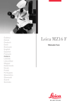
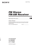
Training Manual
DVP-NS415
DVP-NS655P
DVP-NS875P
5th Generation
DVD Player
Models:
DVP-NS300
DVP-NS315
DVP-NS400D
DVP-NS415
DVP-NS500P
DVP-NS700P
DVP-NS715P
DVP-NS755P
DVP-NC600
DVP-NC650
DVP-NC655P
DVP-CX875P
DVP-F25
DVO-F41MS
Circuit Descriptions & Troubleshooting
Table of Contents
1. What’s New? ......................................1
6. Troubleshooting ...............................27
Physical Differences ............................................. 1
Features ................................................................. 2
Dual Laser Optical Block ..................................... 3
Process Flow ........................................................ 27
Disc Identification.................................................. 5
Super Audio Compact Disc (SACD) .................. 6
Logos ...................................................................... 7
Powering the Unit................................................. 34
CD Mechanism Normal Operation .................... 35
Disc Loading, Stacker and Disc Clamping
Motor Drive Access .............................................. 37
Video Noise Reduction ........................................ 8
2. Block diagram ..................................10
3. Power Supply ...................................12
Plug-In Communications .................................... 15
4. Testing and Test Point Access .......18
5. Testing ...............................................22
Jigs and Tools ....................................................... 25
7. Service / Test Mode .........................32
8. Mechanical Operation .....................35
1. What’s New?
Chapter 1 - What’s New?
The popular fifth generation Sony DVD players introduced for the years 2001 and 2002 are physically and
electrically different from previous generation players; they have greater appeal and are lower in cost.
Physical Differences
The single disc players are thinner than the previous fourth generation models and take up less vertical space.
Some models are available in both black and silver (same model number) to blend with different decors. Two
models, DVP-F25 and DVP-F41, have slot type loading (like a car CD player) which makes them smaller; they
can also be played horizontally or vertically; a pedestal base can be attached to the side for vertical mounting, as
in Figure 1-1.
DVD slot
Models DVP-F25 / F41
FIGURE 1-1 - VERTICAL MOUNTED “F” SERIES DVD PLAYER
1
1. What’s New?
Features
These players can play computer “burned” -R and +RW (CD or DVD) discs. A built-in MP-3 decoder allows MP3 encoded CD’s to be played. All 5th generation players have outputs for composite video, component video (Y,
R-Y, B-Y) and Dolby Digital ™ / dts ® digital coax/optical digital audio (except DVP-F25 and DVP-F41 models
which only have high grade component video and optical audio outputs) Other features on some models are:
multi-format SACD music CD PB (audio); and high resolution 480p progressive video output.
Table 1-1 shows some of the features of the Fifth Generation models.
Table 1-1 - Sony’s Popular Fifth Generation DVD Players
Model Number
Intro
Year *
Type
Feature
DVP-NS300
2001
1 disc tray
DVP-NS315
2002
1 disc tray
Case = Blk or Silver finish. Does not
PB –R or +RW discs.
Black or Silver finish
DVP- NS400D
2001
1 disc tray
Built in 5.1 Digital Dolby Decoder
DVP- NS415
2002
1 disc tray
Silver, Built in 5.1 Digital Dolby
Decoder
DVP- NS500P
2001
1 disc tray
Progressive scan
DVP- NS700P
DVP- NS715P
2001
2002
1 disc tray
1 disc tray
Progressive scan
Progressive scan, Silver
DVP- NS755P
2002
1 disc tray
Progressive scan, SACD, Built in 5.1
Digital Dolby Decoder, Blk.
DVP-NC600
2001
5 disc Changer
No thinner case like the tray units.
DVP-NC650
2001
5 disc Changer
SACD
DVP-NC655P
2002
5 disc Changer
Progressive scan, Blk/Silver.
DVP-CX875P
2002
300 disc changer
Progressive scan, Built in 5.1 Digital
Dolby Decoder.
DVP-F25
DVP-F41MS
2002
2002
1 disc slot
1 disc slot
Case = Blk or Silver finish.
Memory stick for JPEG pix view
* Optical Assemblies for 2001 year Models are KHM240AAA and KHM250AAA Optical
Assemblies for 2002 year Models are KHM270AAA and KHM275AHA.
2
1. What’s New?
Dual Laser Optical Block
Disc Playback Characteristics
All fifth generation DVD models, (except basic model DVP-NS300) can play back computer made –R or +RW
discs.
Computer made (burned) –R or +RW discs have different characteristics than machine stamped counterparts
and stamped CDs have different characteristics than DVDs. To insure full compatibility, the optical block uses
two lasers. One is optimized for CDs and the other for DVDs.
To understand how separate lasers insure playback of computer burned discs, some basics are explained here.
The reflected Laser light from the disc to the optical block contains the data. DVD discs (including DVD-R and
+RW discs) reflect best in the 650-635nM wavelength band. CD discs (including –R or +RW discs) reflect light
best at 780nM.
Figure 1-2 shows that maximum CD-R disc reflection (RF) occurs at 780nM. Since –R or +RW discs have lower
reflectivity than stamped discs (reflectivity also varies from brand to brand) output is maximized if two lasers are
used: one operating at 648nM for DVDs and another at 780nM for CDs.
Optical Pick-up
CD = 1.2cm
Reflective
Intensity for
CD-R
DVD=0.6cm
650nM
780nM
KHM-240
Lens
Wavelength
For CD
For DVD
FIGURE 1-2
3
1. What’s New?
Disc Warp Correction
Because of the finer DVD pitch, the laser must be perpendicular to the disc for maximum RF output from the
optical block. Figure 1-3 illustrates the differences between old servo tilt mechanism system (A) and the new
DTC system (B) that keeps the laser beam perpendicular. In earlier generations, a tilt servo (A) adjusted the
angle of the laser platform to keep the monitored RF level at peak. This system is complex and the platform can
“bottom out”, limiting its range.
DISC
PIVOTS UP
LENS
MOTOR
PIVOT
OPTICAL
ASSEMBLY
WHOLE
ASSEMBLY
ROTATES
FROM
HORIZONTAL
DISC
WHOLE
ASSEMBLY
ROTATES
FROM
HORIZONTAL
LENS
PIVOT
OPTICAL
ASSEMBLY
A TILT SERVO WARP
DISC COMPENSATION
PIVOTS
DOWN
(LIMITED RANGE)
ILLUSTRATES
ROTATION OF
LENS
ONLY
DISC
LENS
OPTICAL
ASSEMBLY
ASSEMBLY REMAINS
HORIZONTAL
DISC
ILLUSTRATES
ROTATION OF
LENS
ONLY
LENS
OPTICAL
ASSEMBLY
B DTC WARP
DISC COMPENSATION
ASSEMBLY REMAINS
HORIZONTAL
FIGURE 1-3 - TILT SERVO (A) VS. DTC (B)
4
GGW5 1545
4/9/03
1. What’s New?
In fifth generation DVD players, an ingenious Dynamic Tilt Correction (DTC) system replaces the tilt servo.
Warped disc readability is achieved by tilting the lens during focus correction. The greater the focus correction,
the more the tilt.
The DTC concept and mechanics are as follows:
The DVD disc information layer is at a height determined by the spindle motor hub. This is considered as the
mechanical focus center of the lens. As the optical block moves towards the outside of the disc, disc warp
increases. At the points where the disc is angled up by warp, the focus point also moves up to compensate.
Raising the focal point causes the lens to change its angle and remain perpendicular to the disc. Conversely,
when the disc angles down (Figure 1-2 B), the lens focus goes below center and the lens tilts in the opposite
direction.
Mechanically, DTC is achieved by modifying the lens supports. The front lens supports are stronger than the
rear. See Figure 1-4. As the lens moves up, it is tilted toward the weaker support. As it moves down, the lens is
tilted toward the stronger support. The tilt is always in the direction of the warpage so the lens remains perpendicular
to the disc.
Figure 1-4 - Lens
Retaining DTC System
Lens
Weak
Rear
Support
Stronger
Front
Support
FIGURE 1-4 - DTC SYSTEM
Disc Identification
The DVD player first determines what type of disc is in the tray before playing it. The player powers up one of the
lasers and begins looking for the disc’s information layer(s). The time it takes to find a layer determines how
deep the layer is inside the disc (T=0.6cm, 2T =1.2cm). Because the tracking servo is disabled at this time, the
lens will continue past the focus point of the DVC and look for a second information layer (DL disc). The disc ID
method is shown in Figure 1-5. This procedure is repeated with the second laser to insure identification of the
lower output –R and +RW discs.
5
1. What’s New?
Figure 1-5 also shows that the laser takes the least time to find a DVD disc (Figure 1-5, B, C, or D). If a second
focal point is also found, the disc is either a dual layer DVD (Figure 1-5 C) or SACD (Figure 1-5 D).
DISC IDENTIFICATION
Disc Type
CD
CD
2T
A
INFO LAYER
1.2 CM
DISC ENTRY
B
DVD/
SACD
SL
T
SL
INFO LAYER
0.6 CM
DISC ENTRY
DL
T
C
DVD/
SACD
DL
tDL
2nd LAYER
1st LAYER
0.6 CM
DISC ENTRY
T
D
SACDHybrid
0.6 CM
1.2 CM
SACD layer
t hybrid
CD layer
CD layer
HD LAYER
DISC ENTRY
FIGURE 1-5 - DISC IDENTIFICATION
Super Audio Compact Disc (SACD)
There are three types of SACDs, all played from the bottom of the disc (disc is not flipped over): See Figure
1-6.
1. Single Layer: The single high-density (HD) layer can contain 2 channel and multi-channel DSD recordings,
text (such as song tiles and lyrics), video clips and graphics.
6
1. What’s New?
2. Dual layer - Two layers with twice the playing time / information as a single layer.
3. Hybrid layer – Contains one HD layer and a standard CD layer so it can be played on any standard CD player
too.
Single layer disc
HD
layer
Dual layer disc
2 HD layers
Hybrid disc
CD layer
HD
layer
FIGURE 1-6 - SACD TYPES
Logos
High-end products that can play one or all versions of SACD discs have at least one of three of the logos
shown in Figure 1-7.
Front L
Center
Front R
Subwoofer
Rear L
Rear R
FIGURE 1-7 -SACD LOGOS
7
1. What’s New?
Video Noise Reduction
Block Noise Reduction (BNR)
BNR reduces dissimilarities (noise) at the edges of blocks (Figure 1-8).
Block Noise Reduction
The Block Noise Reduction reduces noise at vertical
rising (block) edges caused by the MPEG format.
The picture looks more smother and more natural.
Picture details, even very small once, are not effected.
FIGURE 1-8 - BLOCK NOISE REDUCTION
Digital Video Enhancer (DVE)
DVE corrects the frequency response of the video signal and emphasizes picture details, see Figure 1-9. Since
DVE (Digital Video Enhancer) emphasizes BLOCK NOISE, the BNR circuit is used before the DVE .
DVE = Digital Video Enhancer
it emphasizes picture details
U
f
: Original Signal
: Optimized Signal
FIGURE 1-9 - DIGITAL VIDEO ENHANCER
8
1. What’s New?
Digital Video Enhancer & Block Noise
Reduction
Former generation (year 2000)
Might emphasize
DVE
DVE
Block Noise!
5th generation
BNR
BNR
At first,reduce
Block Noise.
DVE
DVE
No emphasis of Block Noise, clear edge and
details retained.
FIGURE 1-10 - BNR AND DVE ORDER
9
2. Block Diagram
Chapter 2 - Block Diagram
Figure 2-1 shows a block diagram of fifth generation DVD players. They have the following features:
•
New type of optical pickup unit. (CD or DVD laser selection not shown.)
•
All analog Driver functions input to one IC (“IF Con”).
•
No External RAM for Syscon IC.
•
Block Noise Reduction IC.
•
ARP and Servo DSP is combined in one IC.
16MB
DRAM
Base Unit
16/ 64MB
SDRAM
DVD/CD
PD IC
BNR
RF Amp
ARP
Servo
DSP
CDDOUT
CDData
V,Y,C
AV
Decoder
Video Buffer
SPDIF
CDBCK/LRCK
Focus
Coil
Parallel Bus
Tracking
Coil
INLIMIT
Sensor
SPDIF OUT
FLASH or OTP
Focus / Tracking
Coil Drive,
Spindle / Sled/
Loading Motor
Drive
M
SP_Motor
M
Sled Motor
EEPROM
SACD
DECODER
M
Audio
DSP
Syscon
SACD
BASS
Manag.
Loading
Motor
Chuck Tray
Detect
Receiver RC
)
Audio
D/A
Converter
IF Con
SW
Regulator
Fn Key
FIGURE 2-1 - BLOCK DIAGRAM
10
ND401
FLD
2. Block Diagram
CIRCUIT BOARDS LOCATION
DVP-NS400/700
POWER BLOCK (HS15S1U)
NS500V)
(SWITCHING REGULATOR)
HS13SO3 IN -NS400
AI-23 FOR NS-400
(COMPLETELY DIFFERENT,
INCLUDES: AUDIO/VIDEO/
INTERFACE CONTROL
AV-59 NOT IN -NS400
(AUDIO/VIDEO OUT)
ER-15 IN -NS400
SI-31
(REMOTE COMMANDER
RECEIVER)
NOT IN -NS400
MS-81
(LOADING)
MB-101
(SIGNAL PROCESS, SERVO)
MB-98 IN -NS400
IF-84
(INTERFACE CONTROL)
FIGURE
CIRCUIT BOARD
FIGURE
2-22-2-- CIRCUIT
BOARD
Table 2-1 - MB Board Main IC Functions
IC Name
DVP-NS400
Ref Number
DVP-NS700
Ref Number
RF Amp /
Digital
Servo
IC202
IC201
DVD/CD RF Amp,
Servo
EEPROM
IC101
IC101
Servo Setting Data,
Emer. History, Hour
meter, Disc
Parameters.
Flash /
OTP
IC107
IC106 &
IC107
Start up instructions /
sequence ROM
Syscon
IC103
IC104
Overall Operation
(ARP) /
Servo DSP
Advanced
RF
Processor
IC302
IC302
CD/DVD Data
Processing, Servo
Control.
16M DRAM
BNR
IC303
IC601
IC301
IC504
RAM for ARP IC302
Black Noise
Reduction
A/V
Decoder
IC503
IC502
MPEG2, AC-3 ®
(Dolby Digital)
decoder
64M
SDRAM
Analog
Servo
IC504 /
IC505
IC401
IC507
RAM for A/V Decoder
IC202
Analog Servo Control
11
Purpose
3. Power Supply
Chapter 3 - Power Supply
Power Supply
The 5th Generation power supplies have the following features:
•
No STANDBY circuit (Hard wire ON / OFF switch SW101).
•
Simple MAIN POWER SUPPLY circuit. Q101 = switching osc. Q102 / PC101 / IC301 = feedback.
•
Simple Stdby/Power ON controll.
Figure 3-1 shows a block diagram of the power supply:
HS15S1E BOARD: AEP, UK, AUS, E, EA, HK, KP, ME, RUS, SP, CH
(SEE PAGE 4-53)
Q211
D211 L211
HS15S1U BOARD: US, CND
(SEE PAGE 4-61)
HS15S1J BOARD: TW
(SEE PAGE 4-57)
D221
L221
Q311
12
US. CND. TW
SW101
POWER
EXCEPT
US. CND. TW
D311
L311
D611
L611
L101
LINE
FILTER
1
2
+5V
P311
Q611
P611
8
F101
AC IN
SW
6 +11V
7
EVER +11V
13
SW
+3.3V
D413
L102
LINE
FILTER
T101
Q411
+3.3V
REG
CN101
IC411
Q101, 102
OSC
EVER
+3.3V
11
D621 (ON/STANDBY)
Q621, 622
LED DRIVE
SHUNT
REG
EVER
-11V
L511
D511
3
Q712
POWER
CONTROL
2
P-CONT
P-DET
1
IC301
EVER +3.3V
PC101
PHOTO
COUPLER
SHUNT
REG
FIGURE 3-1 - POWER SUPPLY
Power ON Operation
The power supply circuitry before T101 (Primary) and after (Secondary) are explained. Refer to Figures 3-1 for
the block diagram. The load and additional regulators are shown in Figure 3-2.
Primary
After closing main switch SW101, oscillator circuit Q101 and the primary coils of T101starts. Regulation comes
from sampling the secondary +3.3 V at L611. The sample is sent to inverter/shunt regulator IC301, to the optocoupler PC101 and finally back to oscillator Q101.
EVER +3,3V from Q411 is switched via the other leg of SW101 and is applied to power ON LED D621 (RED)
drive. It is also applied to IC404/pin19 (not shown) as a P-DET signal. The output of IC404 controls the rest of
the power supply secondary circuit via the P-CONT line. EVER +3.3V powers IC404, IR remote receiver, cursor
stick and audio muting (all not shown).
12
3. Power Supply
Keep in mind that SW101 is a “hard off” switch. With the switch OFF, the unit will not turn ON with the remote.
Soft ON/OFF(standby) is controlled by the P-CONT line and Q712: it controls +11V via Q211, +5V via Q311, and
SW+3.3V via Q611.
Power Supply 8
AV-59 Board
AV-59 BOARD
AI+5V
CN102
8
21
6
6
CN101
IC101
-5V REG
IN
2
OUT 3
Q206
AU+11V
7
SW-11V
3
IC102
VIDEO
BUFFER
Q201, 205
IC202
AUDIO AMP
IC201
+5V REG
1
IN
OUT 3
IC203
5.1CH FRONT
AUDIO AMP
D201
EVER
+3.3V
MUTE V
5
IC204
5.1CH REAR
AUDIO AMP
IC201
OPTICAL DIGITAL
OUT
IC205
5.1CH
CENTER/WOOFER
AUDIO AMP
OPTICAL
7
8
AUDIO-D/A
FIGURE 3-2 - ADDITIONAL REGULATORS
3.5DVD5
Waveforms
These waveforms were taken at key areas of the power supply:
Figure 3-4 - Scope Shot – Q102/Gate –
Stby Mode. 1.254 Vpp
(small:supply
~0.6 Vpp)
Power
6
Timebase:
2
ms
Q102 / GATE / standby mode
Figure 3-3 - Scope Shot – Q101 / Drain – Stby
Power supply 4
Mode. - 304.5 Vpp Timebase: 0.1 ms
Q101 / Drain / standby mode
13
4/11/03
3. Power Supply
Measurements on the primary side of the power supply
C150
C150
ground for scope
Connect the scope`s ground here
Measurements values on the primary side
Q101, DRAIN voltage
304,5 Vpp
Q101, GATE voltage
12,5 Vpp
Q102, BASE voltage
1,25 Vpp
All measurements use 1:10 probe in standby mode!
For safety reasons do not connect the unit to an AC out outlet!
Use an isolation transformer!
FIGURE 3-5 - HOT AC LOCATIONS
14
3. Power Supply
Plug-In Communications
Figure 3-6 shows the general sequence of IC communications during Plug-in time.
1.
System controller IC104 communicates with Flash Memory to retrieve the Instructions / programs.
In the event the communication with the Flash Memory is not accomplished, System control will inform
Interface IC 404 to switch the power to standby mode.
2.
Similarly the initial communication (Hand Shaking) takes place with IC 503/ AV Decoder and IC302 /ARP.
In the event the communication with these ICs is not accomplished, System control will inform Interface
IC 404 to switch the power to standby mode.
A failure of any of the ICs (IC104, IC503 or IC302) will cause the unit to enter the Standby mode.
IC303
16M
DRAM
Base Unit
IC507
64M
SDRAM
DVD/CD/SACD
PD ICs
IC302
ARP
Servo
DSP
IC502
AV
Decoder
DVP-NS500/700:
IC-Communications
at POWER ON
3Parallel Bus 2
IC106 (Or) IC107
FLASH
OTP
1
IC601
Audio
DSP
IC104
Syscon
IC101
EEPROM
IC603/4
Audio
D/A
Converter
Power on
M
Loading
Motor
Chuck Tray
Detect
)
ND401
FLD
IC404
IF Con
SW
Regulator
Fn Key
FIGURE 3-6
The Plug In communications sequence is as follows:
1. AC plug in.
2. Ever 3.3V is applied to Interface IC404 PIN 78.
3. 401 (8MHz) becomes active.
4. Pcont from IF IC404 / Pin 26 goes HIGH to Power the set.
5. After this sequence of Power ON, the following communications will take place as shown in Figure 3-7:
• Ready Pulse is output from IC404 /Pin 27 (interrupt line) to begin communications with IC103/4.
• System Controller IC103/4 sends chip select from Pin 51 to IC404 / Pin 14.
• System Controller IC103/4 sends bit clock (Pin17) and display data (Pin 26) to IC404.
6. If users command have been initiated, then these commands will be sent from IC404/Pin 16 to IC 103, 104/
Pin 25. Otherwise, IC404 will bring “Pcont” low and RST pulse /Pin 7 will be sent to IC103/4 Pin 76.
7. Set goes to Stby.
15
3. Power Supply
5
User Commands
4
Display Update
26
17
3
Serial Clock
17
14
2
Chip Select
1
Interrupt
6
Stop
SI0
16
SO0
15
SC0
XIFCS
IC404
IFCON
XIFBSY 27
78
26
25
IC103/4
SYSCON
51
20
INT4
XFRST 7
76 3.3v
Pcont
Ever +3,3 V
Plug-In
Start
Red LED
Std-By
IFCONàSYSCON
INT
SYSCONàIFCON
Clock/Data
IFCONàSYSCON
XFRST
Green LED
End
Red LED
1.3 Seconds
FIGURE 3-7 - PLUG IN SEQUENCE
Serial Data Communications after Power ON
The serial data bus connects several ICs and consists of two or three lines. Serial data is transmitted from one
IC to another on a unidirectional line (arrows shown in one direction). This data is accompanied by a clock signal
for a total of two lines in a unidirectional serial communication. The interface control IC404 and syscon IC104
communicate bidirectionally (arrows shown in two directions). Three lines are necessary when bi-directional
transmissions are used. There is a data line for each direction. The additional clock signal makes a total of three
lines for a bi-directional serial bus. The clock signal usually comes from the controlling micro, which in this case
is syscon IC104.
IC104 communications with interface IC404, EEProm IC101, SACD decoder IC806, SACD bass management
IC807 and DSP IC601 are bi-directional.
Syscon communications to the Digital to Analog Converters (DAC) IC603, IC604 are uni-directional.
16
3. Power Supply
Parallel Data Communications after Power ON
See Figure 3-8
The parallel data bus consists of address lines, data lines, a WE (write enable) and a RE (read enable) line, and
a clock line. The parallel bus is contoleed by system control IC202.
FIGURE 3-8 - COMMUNICATIONS BLOCK
17
4. Testing and Test Point Access
Chapter 4 - Testing and Test Point Access
This section is divided into two parts: 1) Test point access; and 2) testing the RF and servo sections using the
service / test mode.
The signals are generated by the optical assembly’s photo detectors as listed in Table 4-1.
Table 4-1 - Photo Detector and Their Manufactured Signals
Photo
Detector
Signals
Purpose
A-D
TE (DVD only),
FE, PI, Mirror,
RF
(eye
pattern)
TE = DVD tracking error.
FE = Focus error.
PI = “Pull In” is the analog sum of A-D detectors. Disc ID
the disc and MIRR.
MIRR counts tracks and ID disc.
RF = Sum of A-D detectors.
E&F
TE + and TZC
CD tracking error, track counting
G&H
TE – and TZC
CD tracking error, track counting
Access - RF Output
The RF test point is easily accessed. See Figures 4-1 through 4-3. Figure 4-4 shows the RF waveforms.
RF measurements locations I
1 RF in/PIN2
FIGURE 4-1 - IC201 RF TEST POINT
18
4. Testing and Test Point Access
MB-101 board / side A
IC502
CPUCK TP
IC104
IC302
Testpunkt RF-Monitor
CN104/PIN1
FIGURE 4-2 - ALTERNATE RF TEST POINT
RF measurements locations III
IC302
2 PIN128/RF in 2 & PIN131/RF in 1
FIGURE 4-3
19
4. Testing and Test Point Access
RF/Servo measurements I
No. 1
~540 mV / RFMON
~460 mV / RFMON
No. 2
RF in 1 & 2 of IC 302
RF in 1 & 2 of IC 302
FIGURE 4-4
Focus and Tracking Error Test Points
Figures 4-5 and 4-6 show the focus test points and waveforms.
PI / TE / FE measurements locations IV
IC302
3 TE / PIN135
4 FE / PIN136
PI / PIN137
FIGURE 4-5
20
4. Testing and Test Point Access
Figure 8-7
RF/Servo measurements III
No. 3
TE
TE
FE
FE
No. 4
FIGURE 4-6
21
5. Testing
Chapter 5 - Testing
RF, Focus-Tracking Servo, Optical Assembly
The service or test mode permits us to repeat a signal so we can see it on the scope and verify its operation. In
the first test, a YEDS-18 CD test disc was used to check focus and optical assembly detectors by looking at the
PI and FE signals.
Entering the Service / Test Mode
1. Using the remote, press these buttons: TITLE, CLEAR, then POWER.
2. From the test menu, select “Drive Manual Operation”; select “Disc type”; select the disc type in the unit.
3. From the “Drive Manual Operation” menu, select “Servo Control”; turn on “1.LD” and 7.FCS.Srch.
4. Connect the CH1 scope probe to “PI” and the CH2 probe to “FE”.
Testing - Focus
After using the service mode to repeat one time operations, the focus, tracking and RF signal levels can be
monitored. Figures 5-1 to 5-4 show normal servo operation.
Figure 5-1 - CD Focus error showing balanced A-D detectors.
st
(FE is equal above and below center). The 1 PI pip occurs at disc entry.
When a CD is played back (YEDS-18).
The Player is in service mode „CD“.
Figure 5-2 - DVD Focus Error showing same detectors are still balanced at the
higher DVD laser frequency. Balanced FE means faster recovery after disturbance
S-Curve: 1,5 Vpp
PI-Level: 1 Vp
A DVD single layer is played back (HLX-503).
The player is in service mode „DVD-SL“.
S-Curve: 1,5 Vpp
PI-Level: 1 Vp
28 ms
56 ms
PI
PI
FE
FE
Figure 5-4 - Hybrid SACD Focus error and PI level shows three pips. 1 = disc
surface entry, 2 = HD layer, 3 = CD layer an equal distance away (28 ms).
Figure 5-3 - DVD Focus Error of a Dual Layer (DL) disc. Two FE signals
of equal amplitude mean both layers can be identified.
A DVD dual layer is played back (HLX-501). S-Curve: max. 1,6 Vpp
The player is in service mode „DVD-DL“.
PI-Level: 1 / 0,8 Vp
When a hybrid disc is played back.
Player is service mode „LCD“.
S-Curve: approx. 0,5 / 2,5 Vpp
PI-Level: approx. 0,8 / 2,3 Vp
26 ms
28 ms
28 ms
PI
PI
FE
FE
2 layers are detected
22
5. Testing
Verifying Focus Layer Jumping:
This check is only possible in service mode. A dual layer disc
must be inserted.
1. Switch ON the “Drive Manual Operation” (2).
2. Next switch to “Disc Type” (1). Now check the inserted disc
Type, select “Disc Type Auto Check” (1). The detected disc
type is shown on th bottom of the screen; it should be “DVD
DL 12 cm”.
3. Push “RETURN” and select “Servo Control” (2).
4. Start disc PB by switching the following ON: “LD ON” (1), “SP
ON” (2), “Focus ON” (3), “TRK ON” (4), “Sled ON” (5) and
“CLVA ON” (6).
FIGURE 5-5 - TRACK / LAYER JUMP
SCREEN
5. Push “RETURN” once again and select “Track/Layer Jump” (3).
6. On the right side of the screen (Figure 5-5) you will see the information for controlling layer jumping. Use the
UP & Down buttons of the remote controller as follows:
•
L1 to L0 push once the “UP” button.
•
L0 to L1 push once the “DOWN” button.
The layer jump will be performed. After jumping, PB will continue on the other layer as indicated by the advancing
sector / frame numbers .
Figure 5-6 shows the track jump to the upper layer. The top waveform is PI and the bottom waveform shows FE.
The focus layer jump was from L0 to L1. The player is in service mode with a DVD „DL disc”. Figure 5-7 shows
the track jump back to the lower layer. The top waveform is PI and the bottom waveform shows FE. The focus
layer jump was from L1 to L0. The player is in service mode with a DVD „DL disc”.
PI
PI
FE
FE
FIGURE 5-6 - ELECTRICAL VERIFICATION
OF JUMP TO THE UPPER DISC LAYER
FIGURE 5-7 - ELECTRICAL VERIFICATION OF JUMP TO THE LOWER DISC
23
5. Testing
Testing - Tracking Servo Checks
Table 5-1 lists the ICs responsible for track jump and basic servo operation.
Table 5-1 - Tracking IC Responsibilities
Device
Servo
Track
Jump
Purpose
RF Amp IC201
Servo IC302
Yes
Yes
Yes
Creates TE voltage
Sets tracking position
Driver IC202
Yes
Yes
Voltage to current driver
Tracing coil (Optics)
Yes
Yes
Corrects lens position
System Control
(Syscon) IC104
Yes
Determines when to jump (look for another
location)
EEPROM IC101
Yes
Stores previous / future jump location.
HGA IC403
Yes
Expansion port for Syscon IC104
Testing -Checking the TE signal:
This check is only possible in service mode.
1. On the remote press buttons: Title, clear, then Power.
2. A SL test disc must be inserted.
3. Switch ON the “Drive Manual Operation” (2).
4. Next switch to “Disc Type” (1). Now check the inserted disc Type, select “Disc Type Auto Check” (1). The
detected disc type is shown on th bottom of the screen; it should be “DVD SL 12 cm.
5. Push “RETURN” and select “Servo Control” (2).
6. Start PB by switching “LD ON” (1), “SP ON” (2) and “Focus ON” (3). [See Figure 5-8]
7. The measured traverse TE signal level is aproximately 1,6 Vpp. The DC-Level in relation to „VC” is around
780 mV.
FIGURE 4-8 - SERVO CONTROL TV SCREEN IN DVD SERVICE MODE
24
5. Testing
Testing - TE traverse check:
Earlier you checked the FE signal for symmetry (equal
amount of signal above and below the center Vc point. That
proved the A-D detectors were balanced (equal output) at
normal PB levels. The Traverse waveform (Figure 5-9)
checks the balance of the same detectors dynamically at a
higher light level such as when the optical assembly is
moving to another track or layer.
Figure 5-9 - Traverse waveforms quickly checks the detectors
dynamically. TE is disabled (turned OFF) from Figure 9-18 screen to
produce this waveform. Signal level approx. 1,6 Vpp SL disc. DC level in
relation to „VC“ is ~780 mV.
Jigs and Tools
Extender cable package J6090-116A permits you to move
the Mechanism Deck so you can access areas underneath. You can also access under the MB board and
see the Mechanism operation from the bottom. See Figure 5-10.
FIGURE 5-10 - USING THE TRANSPORT EXTENSION JIG J6090-116A
25
5. Testing
Figure
5-11b
- “Jigged”
DVD
Player
Figure
5-11a
- “Jigged”
DVD
Player
Top
View
Top
View
Figure 5-11b - “Jigged” DVD Player Side View
26
6. Troubleshooting
Chapter 6 - Troubleshooting
Process Flow
This section is divided into flow charts targeted for general symptoms.
A. No Test Mode Menu
B. No Power
C. Checking the Laser
No Test Mode Menu
Figure 6-1a diagnoses the symptom of No Test Mode Menu.
• If 33 MHz is available at Pin 77 at IC 103 / 104, communications between Flash ROM and Syscon are
probably OK.
• If 33MHz clock output is missing at Pin 77, either System controller and related power supply circuits or the
Crystal may be faulty. Try changing the Crystal before replacing the IC.
Trouble Shooting : No Test Mode Menu
If the ICs are different, IC no. marked in red
= NS700
Std-By
Can Enter
Test Mode
Yes
No
Visual Check
1. SYSCON – IC103 / 104
2. ROM - IC107 or 108 / 106 or 107
3. AVD – IC503 / 502
4. ARP&SERVO – IC302
Measure the clock frequency
at CPUCK
(PIN,77) of the SYSTEM
CONTROL (IC103 / 104)
Go to
1.1
8.25 Mhz
output
33Mhz Out put
Communication
To Flash ROM is OK
Fixed to
“H” or “L”,
FIGURE 6-1a - NO TEST MODE
27
Go to
1.2
SYSCON
IC103/4 or X101
Faulty
6. Troubleshooting
In Figure 6-1b, missing read/write data may be caused by a power supply failure or if Syscon IC104 held is in
constant reset.
1.1 Trouble Shooting : No Test Mode Menu _ No 33Mhz output
Std-By
If the ICs are different, IC no. marked in red = NS700
Yes
Can Enter
Test Mode
No
No 33 Mhz output at Pin 77
Of IC 103/104 (Syscon)
No
SYSTEM CONTROL (IC103/104),
ROM (IC107 or IC108/106 or 107),
AVD (IC503/502),
ARP&SERVO (IC302).
Power supply
voltage check
76
Reset signal
check
XFRRST
IC103/IC104
Should not be fixed to „H“, „L“ or
something in between!
XRD 70
28 OE
H=OK
(3,3 V)
IC103/104
XRD, XWRH, CS0X,
HA 0-21 & HD 0-15
signals check
SYSCON
XWRH 71
11 WE
CS0X
26 CE
IC107/106
58
HA & HD
Flash ROM
HA & HD
FIGURE 6-1b - NO TEST MODE
If 33 MHz is present but not the Test Mode menu, then follow the procedure in figure 6-1c, at IC503 AV
Decoder IC.
Trouble Shooting : No Test Mode Menu (33Mhz output OK)
If the ICs are different, IC no. marked in red = NS700
Std-By
Can Enter
Test Mode
Yes
No
AVD Check
33 Mhz output at Pin 77
Of IC 103/104 (Syscon)
Yes
Check 95Mz
At Pin 149?
27MHz from
PLL IC102
Yes
95Mz
182
No
SCLKIN
AVD-IC503/502
1.2
Check 27Mz
Across Pin 182
Pin 180
IC503/502
CXD1933Q
Check IC503/502
FIGURE 6-1b - NO TEST MODE (CON’T)
28
CLKI 180
6. Troubleshooting
Figure 6-1d shows the Pins for “Chip Select” of the System Controller.
Check the source of the signal if the chip select pins do not carry any signal and/or if they are constantly at a fixed
voltage.
Trouble Shooting : No Test Mode Menu (33Mhz output OK)
If the ICs are different, IC no. marked in red = NS700
53
X101
54
IC103/IC104
SYSCON
57
CE
IC107 / 106 (Flash)
58 CS0X
59 CS1X
Pin 191(HAD22)
of IC503 / 502
IC302 ARP
CXD9635R
XWAIT
CS7X
CS6X
C
CS5X
60 CS2X
CS3X
XAVDCS2
CS4X
Pin 190 (HAD23) of
IC503 / 502
61 62 63 64 65 66 67 68
XAVDCS3
Pin23 (XCS)
Pin 24(HCS)
Pin 25 (XWAT)
FIGURE 6-1d - NO TEST MODE (CON’T)
Figure 6-1e shows the flow of INT (Interrupt) signal between the ICs.
Note the interrupt pulse on the CDT screen shot.
Trouble Shooting : No Test Mode Menu - 33Mhz output
If the ICs are different, IC no. marked in red = NS700
Time:
20 µS
•Destination IC has carried out the instruction
Level:
•Waiting to send data
(No Clock / No CS from Slave to Master)
1V
INT signal Check
25
IC302
ARP
RF
Servo
3.3V
21
22 3.3V
26
17
18
27
51 IFBSY
INT 4 = “H” 20
78
INT 1 = “H”
INT 2 = “H”
48
84
56
57
IC503 / 502
AV
223
decoder
IC103 / 104
INT 5 = “L” 21
SYSCON
MB91307APFV-
107
IC701 / 601
AUDIO
DSP
107
16
INT 0 = “H”
INT 6 = “H” 22
FIGURE 6-1e - NO TEST MODE (CON’T)
29
IC104 /
404
IF
CON
27
6. Troubleshooting
No Power
Several simple things can cause NO Power in this DVD player: Refer to Figure 6-2.
In-limit Sensor:
If a In-Limit sensor is defective, IC302 will cause the System Controller to shut off power.
Also, check the “INLIM” sensor signal to ARP. If there is no change in the voltage at Pin 166 of ARP (IC302),
check the “INLIM” sensor or flex cable continuity to the switch.
VCO Voltage:
The VCO voltage varies between 1.3 and 2.6 Volts. If outside of this range, the VCO is not operating and the unit
will shut down. Check this voltage after switching ON the set with a disc inserted.
Trouble Shooting Tips
No Power
Check VCO
At Pin 106
IC 302
VCO 1.3 ~ 2.6 V
(Varies from model)
If ‘0’ volt indicates no oscillation
Check limit
Switch Pin 166
Check Pin 106
While turning on off
CN202
IC302
ARP
166
GI00/INT2
7
INLIM
INLIM
Sensor
No change?
Yes
IC 302 def
FIGURE 6-2 - NO POWER FLOW CHART
Checking Laser Current
The laser diode is extremely sensitive to static electricity and should not be probed with test probes. Laser diode
current can be checked by determining the voltage drop on the emitter resistors of Q201 and converting it to
current using ohms law. See Figure 6-3.
30
6. Troubleshooting
Emitter current IE is calculated as: IE=V/RE. Since in our example RE consists of two parallel resistors, the
equation becomes IE=V/(1/(1/R207)+(1/R208)). In our example V=0.9V and the emitter resistors are both 33
ohms, so the calculation becomes IE=0.9/(1/(1/33)+(1/33)) = 0.9/(1/(0.030)+(0.030) = 0.9/16.6 = 0.054A or 56mA.
IC no. marked in red = NS700
IC201
DVD-LD out PIN 25
How to test Laser Diode?
CD-LD out PIN 26
IC202
V
R208
33 ohm
R207
33ohm
4
Laser Diode
of OPU
DVD/CD -LD out
25
Q201
3.4
2.4
FIGURE 6-3 - LASER DIODE CHECKING
31
7. Service / Test Mode
Chapter 7 - Service / Test Mode
Service mode testing consists of the following:
1. Initial Communications
2. Entering the Test Mode
3. Contents of the Test Mode
Initial Communications
Initial communications must occur before the unit remains ON and the test mode can be accessed. Therefore,
if the unit does not power up, you must confirm the communications between a pair of ICs. The flow chart in
Figure 7-1 helps you do this.
This process will determine if the data in the slave IC can be accessed, read and written.
If communications fail, error codes will be out put. Each error code identifies error type and IC stage where it
occurred.
How does the test mode operate?
Read the data in
the same
locations
Activate Main
IC as Master
Select a
SLAVE IC
Verify WRITE & READ
Data.
Access selected
Address locations of
Slave IC
WRITE &
READ data
Same?
Read the current
Data and save
# Different
Process of
Writing the
data
No
Yes
Error not
detected
Write specific data
In the above address
FIGURE 7-1 - DEAD SET / NO INITIAL COMMUNICATIONS
32
Error code
displayed
7. Service / Test Mode
Entering the Test Mode
Figure 7-2 shows how to enter the test mode. Once in the test mode, there are six main diagnoses in the test
mode menu.
TEST MODE
Press
TITLE
CLEAR
POWER
Please use Remcon (previous generation) for using Numbered
keys
Model code
FIGURE 7-2 - ENTERING THE TEST MODE
Contents of the Test Mode
System control diagnosis can give the diagnostic information in the “All”- check or for individual stages. Refer to
Figure 7-3.
Once you select “All”, the system
controller will communicate with
stages and if there is an error, its
code will be displayed.
You may also choose individual
stages for diagnosis.
TEST MODE
Select ‘0’ in the Main Test mode to view ‘Syscon Diagnosis’
Please refer the service manual for
more details.
FIGURE 7-3 - FIRST PAGE OF THE TEST MODE
33
8. Mechanical Operation
Chapter 8 - Mechanical Operation
The model DAV-C770 / C990 is an AM/FM 5.1 channel receiver with a 5 disc CD/DVD player. The CD/DVD
service information is found in the core HCD-C770 / C990 service manual. The core manual does not have part
numbers for the AM antenna, speakers and remote (1-477-332-11).
This new 5-disc changer will require alignment if gears are replaced.
FIGURE 8-1 - DAV-C990 CORE UNIT
This single slot disc entry mechanism uses three motors, two rotary encoder sensors (for transport position) and
seven disc location sensors. The repair information is grouped as follows:
Powering the Unit
CD Mechanism Normal Operation
Disc loading, Stacker and Disc Clamping Motor Drive Access
Gear Alignment (Concepts, Procedure and Testing)
Powering the Unit
The top cover contains the CD operation buttons that must be connected for the mechanism to operate.
34
8. Mechanical Operation
1. Remove the top cover, unplug black connector CN807 (power ON to micro) and lay the top panel on the side.
Do not shear or disconnect the white ribbon connector (CN814 to CN005).
2. Plug the unit into AC and press the power ON button. The unit will not power ON until the micro receives the
power ON via CN807.
3. On the front panel circuit board as shown in Figure 8-2, jump CN807. The unit should power up and show
the model number in the display followed by “Ready”.
CN807
plug &
socket
FIGURE 8-2 - COVER OFF / POWER ON
CD Mechanism Normal Operation
Loading
The disc entry is detected either by a photodetector or by Switch SW-11 closing. The loading motor starts and
turns rollers to pull the disc in. The remaining switches on top, SW-11 to 18, shown in Figure 8-3 and Table 8-1,
determine the position of the disc and its size to the microprocessor. The disc enters, overshoots the center and
returns to center (loading motor reverses) so SW-14 momentarily opens. Figure 8-4 lists the switch positions
during loading and Disc IN. O = Open, C = Closed, M = Momentarily.
Photodetector
SW-11
Front
FIGURE 8-3 - CD MECH - TOP VIEW
35
8. Mechanical Operation
Mode
SW
SW
15
17 18
16
SW
13
SW
11
Switch
boards
14
All switches = Open
a) No Disc
SW
SW
M
C
M
M
SW
SW
C
M
Switch
boards
M
B) Loading
SW
SW
SW
C
O C
C
O
SW
O
Switch
boards
C
c) Disc IN
FIGURE 8-4 - DISC SWITCH STATES
Table 8-1 - Disc Position Switches
Mode
SW-18
SW-17
SW-16
SW-15
SW-14
SW-13
SW-11
No disc
Open
Open
Open
Open
Open
Open
Open
Loading
Moment
ary
Moment
ary
Moment
ary
Closed
Closed
Closed
Moment
ary
Disc IN
Closed
Open
Open
Closed
Closed
Closed
Open
Mini
Disc In
Closed
Open
Open
Closed
Open
Open
Open
CD Playback
When SW-14 closes again during disc overshoot, the loading sequence ends (motor stops) and CD Playback
sequence begins. The CD clamping motor turns ON to raise the laser assembly platform to the centered disc.
Rotary encoder 2 (Figure 5-6) monitors the position of the laser platform. As the laser platform reaches the
clamped position, the loading rollers are geared away from the disc. The clamped disc can spin / play.
36
8. Mechanical Operation
Stacker Disc Storage
If another disc is selected for PB, the mechanism will release the clamped disc and store it into the rear stacker
compartment before extracting the second disc. The clamping motor reverses to release the disc into the rollers
and engage the rear stacker rollers. Meanwhile the stacker motor positions the rear stacker tray height. When
rotary encoder 1 senses the correct stacker storage tray position, the loading motor rolls the disc into the stacker
slot. Final disc location switches SW-16 and 17 determine that disc to storage tray is complete and reverses the
loading motor to disengage the disc so the tray can move to the new disc slot.
Disc loading, Stacker and Disc Clamping Motor Drive Access
As shown in Figure 8-5, four screws secure the CD mechanism.
Figure 12-5 CD Mechanism Removal – 4 screws
1
3
3
22
4
4
FIGURE 8-5 - DISC MECHANISM REMOVAL - TOP VIEW - 4 SCREWS
Figure 8-6 shows a bottom view of the disc mechanism. Table 8-2 lists the drive functions of the motor’s gears
pictured in Figure 8-6.
Table 8-2 - Drive Functions
Drive
Stacker Motor
Disc Loading /
Unloading
Disc Clamping
Gear Alignment
Functions
Motor Stop Sensor
Stacker height
encoder
None
Motor moves stacker up
/down.
Moves disc horizontally
[Into Clamper (PB) or
Stacker (storage)].
Rotary encoder 1
(see Fig 13-8 )
7 disc sensors (Sw
11-18. See Figure
13-3 & Table 13-1)
Disc entry lockout
Clamping Encoder
Stacker Disc
Loading (1 & 2)
1. Prevents disc entry
during PB.
2. Clamps disc
3. Positions rear rollers
for stacker entry.
Rotary encoder 2
(see Fig 13-6 )
37
8. Mechanical Operation
Stacker
Motor
Drive
Disc Loading Drive
Disc Clamping
Drive
Rotary
Encoder 2
FIGURE 8-6 - DISC MECHANISM - BOTTOM VIEW
Gear Alignment (Concepts, Procedure and Testing)
The CD Mechanism gear alignment is grouped into functional names for ease of use:
1. Stacker Height Rotary Encoder (1) Alignment
2. Disc Entry Lockout Gear Alignment
3. Clamping Motor Rotary Encoder (2) Alignment
4. Disc to Stacker Gear Alignment
Stacker Height Rotary Encoder (1) Alignment
Concept: To ensure the rear disc storage tray (stacker) is positioned at the correct height to accept discs, two
gears must be aligned (Figure 8-7).
Procedure: Prealign the black rotary encoder gear as shown in Figure 8-8. Place the Stacker tray on the 3stacker tray screws (Figure 8-9). You will have to rotate the screws to accept the stacker and drop the stacker in
place (this is above the top tray 5 position). Lastly, in Figure 8-9 place the large stacker (communications) gear
in place.
38
8. Mechanical Operation
Stacker Alignment Area
Test: By rotating the large stacking gear while watching the stacker for free vertical travel.
Stacker Alignment Area
FIGURE 8-7 - STACKER GEAR ALIGNMENT AREA
Wide tooth
faces boss
FIGURE 8-8 - ROTARY ENCODER 1 ALIGNMENT
39
8. Mechanical Operation
Rotate screws and drop
stacker pin into slot.
Stacker gear
alignment
hole
FIGURE 8-9 - STACKER GEAR AND SCREW ALIGNMENT
Disc Entry Lockout Gear Alignment
Concept: This single gear alignment prevents another disc from being inserted by locking the entry roller guides
from moving when a disc is clamped.
Procedure: As in Figure 8-10 (mechanism bottom), rotate the Clamping motor gears until cam BU U/D is turned
fully clockwise. Insert the smaller cam (eject lock) gear with the mark as shown.
Test: The first disc entry rollers should be free to move (SW711 in Figure 8-7) Rotate the Chucking motor so the
Cam (BU U/D) is CCW (opposite Figure 8-10). The disc entry rollers should now be inhibited so they just move
enough to close SW711.
FIGURE 8-10 - DISC ENTRY LOCKOUT CAM GEAR
40
8. Mechanical Operation
Clamping Motor Rotary Encoder 2 Alignment
Concept: Rotary encoder 2 (S701) sets the clamping motor limits. Since these gears also control the rear disc
rollers, an encoder 2 misalignment can cause the disc not to travel to the rear stacker or grab the disc during PB
(no spinning).
Procedure: Figure 8-11 (mechanism bottom) shows that the Clamping motor gears are rotated until cam BU U/
D is turned fully counter-clockwise. Place the rotary encoder gear (S701) so its mark faces the plastic projection
in the chassis as shown.
Test: Rotate the clamping motor. At one mechanical limit (unloaded as shown in Figure 8-11), the disc is unclamped.
At the other limit, the disc is clamped. In-between these limits, SW716 and SW717 (Figure 8-4) close freeing the
rear rollers.
Figure 12-11 - Rotary
Encoder 2
- for
Clamping / Stacker
loading
FIGURE 8-11 - ROTARY ENCODER 2 - FOR CLAMPING / STACKER LOADING
Disc to Stacker Gear Alignment
Concept: The clamping motor not only clamps and unclamps the disc, it also drives gears to position the rear
rollers that move the disc into (and from) the stacker.
Procedure: As in Figure 8-12, rotate the clamping motor so the cam BU U/D is CCW (disc clamped). Install the
Cam gear mark as shown. Then as in Figure 8-13, rotate the clamping motor so the cam BU U/D is CW (disc
unclamped). Slide the shaft up. Drop the mode cam gear in mark as shown in Figure 8-13 and secure.
Test: Rotate the clamping motor. At one mechanical limit, the mechanism will clamp the disc and in the other, the
rollers hold the disc. In-between these limits, SW716 and SW717 (Figure 8-4) should close freeing the rear
rollers. See Figures 8-14 and 8-15 for the position of the clamping motor
gears 2
in the two extremes.
Encoder
Clamping / Stacker
loading
FIGURE 8-12 - DISC TO STACKER GEAR ALIGNMENT 1 (DISC CLAMPED)
41
8. Mechanical Operation
FIGURE 8-13 - DISC TO STACKER GEAR ALIGNMENT 2 (DISC UNCLAMPED)
Shaft = Up
Cam BU U/D = CCW
FIGURE 8-14 - UNCLAMPED MECHANISM POSITION
42
8. Mechanical Operation
Shaft = Down
Cam BU U/D = CW
FIGURE 8-15 - DISC CLAMPED, ROLLERS DISENGAGED MECHANISM POSITION
43
and SACD are trademarks of Sony Electronics
Dolby Digital is a registered trademark of Dolby Laboratories Licensing Corporation
dts is a registered trademark of Digital Theater Systems, Inc.
DVD50403
©2003 Sony Electronics Inc.
EMCS - A Service Company
1 Sony Drive
Park Ridge, New Jersey 07656
Reproduction in whole or part without written permission is prohibited. All rights reserved
4/11/03