1
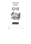
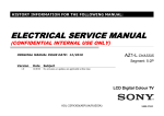
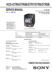
SCD-XE800 SERVICE MANUAL AEP Model UK Model Ver. 1.0 2010.06 Model Name Using Similar Mechanism SCD-XA5400ES Mechanism Type CDM66F1-DVBU101 Optical Pick-up Block Name KHM-313CAB SPECIFICATIONS When a Super Audio CD is played General Playing frequency range 2 Hz to 100 kHz Frequency response 2 Hz to 40 kHz (–3 dB) Dynamic range 100 dB or more Total harmonic distortion rate 0.0035 % or less Wow and flutter Value of measurable limit (±0.001 % W. PEAK) or less Laser Diode Properties When a CD is played Frequency response 2 Hz to 20 kHz (±0.5 dB) Dynamic range 96 dB or more Total harmonic distortion rate 0.0039 % or less Wow and flutter Value of measurable limit (±0.001 % W. PEAK) or less Output jacks Emission duration: Continuous Laser Output*: Less than 44.6 µW * This output is the value measurement at a distance of 200 mm from the objective lens surface on the Optical Pick-up Block with 7 mm aperture. Power requirements 230 V AC, 50/60 Hz Power consumption 20 W Power consumption (during standby mode) 0.5 W Dimensions (w/h/d) 430 × 95 × 295 mm incl. projecting parts Mass (approx.) 3.5 kg Jack type Output level Load impedance Supplied accessories ANALOG OUT L/R Phono jacks 2 Vrms (at 50 kilohms) Over 10 kilohms Audio connecting cord Remote commander Batteries DIGITAL (CD) OUT OPTICAL* Square optical output connector –18 dBm (Light emitting wave length: 660 nm) Coaxial output connector 0.5 Vp-p DIGITAL (CD) OUT COAXIAL* 75 ohms * Outputs only the audio signals of the CD 9-889-883-01 Sony Corporation 2010F05-1 Audio&Video Business Group Red and White plugs (1) RM-ASU097 (1) R03 (size-AAA) (2) Design and specifications are subject to change without notice. I Standby power consumption 0.5 W. I Halogenated flame retardants are not used in the printed wiring boards. SUPERAUDIO CD PLAYER www.electronicsrepair.net SCD-XE800 NOTES ON CHIP COMPONENT REPLACEMENT • Never reuse a disconnected chip component. • Notice that the minus side of a tantalum capacitor may be damaged by heat. FLEXIBLE CIRCUIT BOARD REPAIRING • Keep the temperature of soldering iron around 270 °C during repairing. • Do not touch the soldering iron on the same conductor of the circuit board (within 3 times). • Be careful not to apply force on the conductor when soldering or unsoldering. CAUTION Use of controls or adjustments or performance of procedures other than those specified herein may result in hazardous radiation exposure. This appliance is classified as a CLASS 1 LASER product. This marking is located on the rear exterior. TABLE OF CONTENTS 1. SERVICING NOTES ............................................. 2. DISASSEMBLY 2-1. 2-2. 2-3. 2-4. 2-5. 2-6. 2-9. 2-10. Disassembly Flow ........................................................... Case, Fuse (F001) ........................................................... POWER Board ................................................................ Panel (Loading)............................................................... Front Panel Block ........................................................... CD Mechanism Deck Block (CDM66F1-DVBU101) .................................................. MAIN Board ................................................................... Belt (LD), MOTOR Board, Motor (L) Assy (Loading) (M001) ................................. Base Unit......................................................................... Optical Pick-up Block (KHM-313CAB) ........................ 3. TEST MODE ............................................................ 10 4. DIAGRAMS 2-7. 2-8. 4-1. Block Diagram - RF/SERVO, MAIN Section - .............. 4-2. Block Diagram - PANEL, POWER SUPPLY Section - ........................... 4-3. Schematic Diagram - MAIN Section (1/5) - ................... 4-4. Schematic Diagram - MAIN Section (2/5) - ................... 4-5. Schematic Diagram - MAIN Section (3/5) - ................... 4-6. Schematic Diagram - MAIN Section (4/5) - ................... 4-7. Schematic Diagram - MAIN Section (5/5) - ................... 4-8. Printed Wiring Board - MAIN Section (1/2) - ................ 4-9. Printed Wiring Boards - MAIN Section (2/2) - .............. 4-10. Printed Wiring Boards - PANEL Section - ..................... 4-11. Schematic Diagram - PANEL Section - .......................... 4-12. Printed Wiring Boards - POWER Section - .................... 4-13. Schematic Diagram - POWER Section - ........................ COMPONENTS IDENTIFIED BY MARK 0 OR DOTTED LINE WITH MARK 0 ON THE SCHEMATIC DIAGRAMS AND IN THE PARTS LIST ARE CRITICAL TO SAFE OPERATION. REPLACE THESE COMPONENTS WITH SONY PARTS WHOSE PART NUMBERS APPEAR AS SHOWN IN THIS MANUAL OR IN SUPPLEMENTS PUBLISHED BY SONY. 2 5 5 6 6 7 7 8 8 9 9 14 15 17 18 19 20 21 22 23 24 25 26 27 5. EXPLODED VIEWS 5-1. 5-2. 5-3. 5-4. Case, Front Panel Section ............................................... Chassis Section ............................................................... Mechanism Deck Section (CDM66F1-DVBU101) ........ Base Unit Section............................................................ 6. ELECTRICAL PARTS LIST .............................. 40 Accessories are given in the last of the electrical parts list. SAFETY-RELATED COMPONENT WARNING! 3 36 37 38 39 SCD-XE800 SECTION 1 SERVICING NOTES NOTES ON HANDLING THE OPTICAL PICK-UP BLOCK OR BASE UNIT The laser diode in the optical pick-up block may suffer electrostatic break-down because of the potential difference generated by the charged electrostatic load, etc. on clothing and the human body. During repair, pay attention to electrostatic break-down and also use the procedure in the printed matter which is included in the repair parts. The flexible board is easily damaged and should be handled with care. NOTES ON LASER DIODE EMISSION CHECK The laser beam on this model is concentrated so as to be focused on the disc reflective surface by the objective lens in the optical pickup block. Therefore, when checking the laser diode emission, observe from more than 30 cm away from the objective lens. UNLEADED SOLDER Boards requiring use of unleaded solder are printed with the leadfree mark (LF) indicating the solder contains no lead. (Caution: Some printed circuit boards may not come printed with the lead free mark due to their particular size) : LEAD FREE MARK Unleaded solder has the following characteristics. • Unleaded solder melts at a temperature about 40 °C higher than ordinary solder. Ordinary soldering irons can be used but the iron tip has to be applied to the solder joint for a slightly longer time. Soldering irons using a temperature regulator should be set to about 350 °C. Caution: The printed pattern (copper foil) may peel away if the heated tip is applied for too long, so be careful! • Strong viscosity Unleaded solder is more viscous (sticky, less prone to flow) than ordinary solder so use caution not to let solder bridges occur such as on IC pins, etc. • Usable with ordinary solder It is best to use only unleaded solder but unleaded solder may also be added to ordinary solder. ABOUT THE REMOTE COMMANDER USED IN THE SERVICE MODE When the service mode is operated, the following, remote commander is necessary. (The service mode cannot be operated by remote commander to which this machine is attached) Remote commander (RM-ASP004): Part No. 1-479-272-21 Note: Above-mentioned remote commander is one example. If it is the one printed under a remote commander as “DVD”, any remote commander can be operated. 3 Bottom view SCD-XE800 SECTION 2 DISASSEMBLY • This set can be disassembled in the order shown below. 2-1. DISASSEMBLY FLOW SET 2-2. CASE, FUSE (F001) (Page 5) 2-4. PANEL (LOADING) (Page 6) 2-3. POWER BOARD (Page 6) 2-5. FRONT PANEL BLOCK (Page 7) 2-6. CD MECHANISM DECK BLOCK (CDM66F1-DVBU101) (Page 7) 2-7. MAIN BOARD (Page 8) 2-8. BELT (LD), MOTOR BOARD, MOTOR (L) ASSY (LOADING) (M001) (Page 8) 2-9. BASE UNIT (Page 9) 2-10. OPTICAL PICK-UP BLOCK (KHM-313CAB) (Page 9) Note: Follow the disassembly procedure in the numerical order given. 2-2. CASE, FUSE (F001) 5 case 2 screw (BVTP3 ! 8) 1 two screws (case 3 TP2) 3 4 6 fuse (F001) 3 1 two screws (case 3 TP2) 5 SCD-XE800 2-3. POWER BOARD 2-4. PANEL (LOADING) 6 SCD-XE800 2-5. FRONT PANEL BLOCK 2-6. CD MECHANISM DECK BLOCK (CDM66F1-DVBU101) Note 1: ß 7 SCD-XE800 2-9. BASE UNIT 2-10. OPTICAL PICK-UP BLOCK (KHM-313CAB) 9 SCD-XE800 SECTION 3 TEST MODE Note 1: According to the following procedures when you ship it (Return it to the customer). 1. SERVICE MODE (1) of step 6 and 7 (EEPROM clearness) 2. COLD RESET When the service mode is operated, the following, remote commander is necessary. (The service mode cannot be operated by remote commander to which this machine is attached) Remote commander (RM-ASP004): Part No. 1-479-272-21 Note: Above-mentioned remote commander is one example. If it is the one printed under a remote commander as “DVD”, any remote commander can be operated. COLD RESET The cold reset clears data stored in microcomputer’s RAM to initial conditions. Procedure: 1. Press three buttons of [x], [Z] and [?/1] on the set simultaneously. 2. “COLD RESET” appears on the fluorescent indicator tube. After that, the fluorescent indicator tube becomes blank then the system becomes standby states. PANEL TEST Procedure: 1. Press the [?/1] button to turn on. 2. Press three buttons of [x], [. AMS >, PUSH ENTER] and [?/1] on the set simultaneously. 3. All segments turned on. 4. When [x] button on the set is pressed after half segments in fluorescent indicator tube light up. If you press [x] button on the set again, another half segments in fluorescent indicator tube light up. Pressing [x] button on the set again would cause all segments in fluorescent indicator tube light up. 5. When the [.] button on the remote commander is pressed, “FY10SCD” and the model name are displayed on the fluorescent indicator tube. Note: Each time that the [.] button on the remote commander is pressed, the information displayed on the fluorescent indicator tube changes in the order of Destination, MC version, SYS version, UI version, DVD version, TA version and DSP version. However, this cannot be used in service. 6. Press [N] button on the set, in the key check mode, the fluo- rescent indicator tube displays “K0 J0”. 7. Each time an another button is pressed, “KEY” value increases. However, once a button is pressed, it is no longer taken into account. When all keys are pressed correctly, “K9” and “OK” are alternately displayed. 8. When the [. AMS >, PUSH ENTER] dial on the set is turned in the direction of right,“J0” is changed to “J1”, then ... “J9”. When the [. AMS >, PUSH ENTER] dial on the set is turned in the direction of left, “J0” is changed to “J9”, then ... “J0”. 9. To release from this mode, press three buttons in the same manner as step 2. 10 CDM TEST Aging test mode of CDM. Procedure: 1. Press three buttons of [X], [Z] and [?/1] on the set simultaneously. 2. After the “Open” display blinks, “SINGLE LOADING” is displayed on the fluorescent indicator tube. 3. Press [. AMS >, PUSH ENTER] and then aging starts. 4. To stop aging, Press [x] button. 5. To release from this mode, press three buttons of [X], [Z] and [?/1] on the set simultaneously. SERVICE MODE (1) In this mode, a variety of information is displayed on the fluorescent indicator tube. Refer to the following table for displayed various information. EEPROM CLEAR Procedure: 1. Press two buttons of [x] and [Z] on the set simultaneously for 3 seconds. 2. Various information is displayed on the fluorescent indicator tube. 3. When [R] button is pressed of the remote commander. Rebooting emergence factor appears of toggle article number on the fluorescent indicator tube. 4. When [t] button is pressed of the remote commander. MTK communication error factor appears of toggle article number on the fluorescent indicator tube. 5. When [r] button is pressed of the remote commander. Power ON/OFF error factor appears of toggle article number on the fluorescent indicator tube. 6. Press the button in order of the [4] t [TIME/TEXT] t [CLEAR] on the remote commander of attachment. 7. The message “Complete” is displayed on the fluorescent indicator tube, and EEPROM is cleared. Note: Don't press the [?/1] button when to release from this mode. Necessarily disconnect the power cord. The set doesn't operate when turning off power with [?/1] button of the set. SCD-XE800 List of trouble log Note: “nnn” of toggle article number is a generation frequency of the error. Type Test key Toggle article (Remote commander) number Rebooting emergence (Rebooting emergence Test key2 (R) factor) Serial communications (MTK communication Test key3 (t) error factor) MTK power control (Power ON/OFF error factor) Test key4 (r) Content 2Annn It was not possible to communicate with MTK five seconds more continuously 2Bnnn Compulsion power off demand was received from MTK 2Cnnn Only MTK reset it (Destination, model and region for are the disagreements) 2Dnnn Fails in the start of MTK 2Ennn Fails in the switch of the input mode of MTK 2Fnnn Input mode of MTK changed without permission 2Gnnn Reacts to the key notification no though the communication with MTK is alive 3Annn It was not possible to communicate with MTK with 48ms 3Bnnn A non-standard packet length was received (Excluding 16 bytes) 3Cnnn Checksum NG 3Dnnn Type of the communication header is NG 4Annn Fails in AC ON Initial 4Bnnn Fails in power on of MTK 4Cnnn Initialization response of CDM is abnormal 4Dnnn CDM mechanism error notification is received 4Ennn Input mode is NG MTK is started 4Fnnn MTK input mode switch at time fails usually 4Gnnn Fails in power off of MTK 4Hnnn Fails in power off of CDM 11 SCD-XE800 SERVICE MODE (2) Note: SERVICE MODE (2) is a service mode of Super Audio CD. 1. Service Mode (2) General Description This mode let you make diagnosis and adjustment easily by using the remote commander and the TV screen for Composite input. The instructions, diagnostic results, etc. are given on the TV screen. Be sure to execute the IOP measurement when a base unit is replaced. Preparations: Prepare a TV monitor that has a Composite input. Connection Procedures: Connect the TV monitor to CN1801 on the MAIN board as shown in the diagram. Composite input 4. To execute each function, press its number by using numeric button on the remote commander. 5. To release from this mode, disconnect the power cord. Note: Don't press the [?/1] button when to release from this mode. Necessarily disconnect the power cord. The set doesn't operate when turning off power with [?/1] button of the set. 3. Executing IOP Measurement In order to execute IOP measurement, the following standard procedures must be followed. Procedure: 1. From the top menu of Remocon Diagnosis Menu, select “2 Drive Manual Operation” by pressing the [2] button on the remote commander. The following screen appears on the onscreen display TV monitor VBOUT GND Drive Manual Operation 3 4 CN1801 1. 2. 3. 4. 5. 0. Servo Control Track/Layer Jump Manual Adjustment Mecha test mode MIRR time Adjust Return to Top Menu – MAIN Board (Component Side) – 2. Select “3. Manual Adjustment” by pressing the [3] button on the remote commander. The following screen appears on the on-screen display. IC1101 2. Entering Service Mode (2) Procedure: 1. Press the [?/1] button to turn the power on. 2. Press two buttons of [x] and [Z] on the set simultaneously for 3 seconds 3. The message “SERVICE IN” appears on the fluorescent indicator tube and top menu of the Remocon Diagnosis Menu appears on the on-screen display on the TV screen for Composite input as follows. The model name, IF-con version and Syscon version are displayed at the bottom of the on-screen display. Remocon Diagnosis Menu 0. 1. 2. 3. 4. External Chip Check Servo Parameter Check Drive Manual Operation Emergency History Version Information Model Name :xxx-xxxxx IF-con:Ver.xx.xx(xxxx) Syscon:Ver.x.xxx 12 Manual Adjust 1. Track Balance Adjust: 2. Track Gain Adjust: 3. Focus Balance Adjust: 4. Focus Gain Adjust: 5. Eq Boost Adjust: 6. Iop: 7. TRV. Level: 8. S curve(FE) Level: 9. RFL(PI) Level: 0. MIRR Time: [V][v] Change Value [RETURN]Return to previous menu 3. Select “6. Iop:” by pressing [6] button on the remote commander. 4. Wait until a hexadecimal number appear in the on-screen display as below. SCD-XE800 To Clear Laser Hours and Emergency History Perform Step 6. for EEPROM CLEAR of SERVICE MODE (1). The error code consists of three kinds of error codes. Manual Adjust 1. Track Balance Adjust: 2. Track Gain Adjust: 3. Focus Balance Adjust: 4. Focus Gain Adjust: 5. Eq Boost Adjust: 6. Iop: xx 7. TRV. Level: 8. S curve(FE) Level: 9. RFL(PI) Level: 0. MIRR Time: [ V] [ v] C h a n g e V a l u e [RETURN]Return to previous menu 5. Convert data from hexadecimal to decimal by using conversion table. 6. If the value is smaller than 93 (decimal), then it is OK. However if the value is higher than 93, then BU (base unit) is defective and need to be change. 7. Press the [O RETURN] button on the remote commander to return to previous menu. 8. Press the [0] button on the remote commander to return to the top menu of Remocon Diagnosis Menu. 9. Disconnect the power cord to turn off. Note: Don’t press the [?/1] button when to release from this mode. Necessarily disconnect the power cord. The set doesn’t operate when turning off power with [?/1] button of the set. 4. Checking Emergency History To check the emergency history, please follow the following procedure. Procedure: 1. From the top menu of Remocon Diagnosis Menu, select “3. Emergency History” by pressing the [3] button on the remote commander. The following screen appears on the on-screen display. A. Error code Note: You will not be able to clear only one of either Laser Hours or Emergency History. When EEPROM CLEAR is run, all content will be deleted. Example of Error code 01. 01 05 04 04 00 00 00 00 00 92 46 00 00 00 23 45 Version information The meaning of error code is as below: 01: Communication error (No reply from syscon) 02: Syscon hung up 03: Power OFF request when syscon hung up 19: Thermal shutdown 24: MoveSledHome error 25: Mechanical move error (5 changer) 26: Mechanical move stack error 30: DC motor adjustment error 31: DPD offset adjustment error 32: TE balance adjustment error 33: TE sensor adjustment error 34: TE loop gain adjustment error 35: FE loop gain adjustment error 36: Bad jitter after adjustment 40: Focus NG 42: Focus layer jump NG 51: Spindle stop error 52: Open kick spindle error 60: Focus on error 61: Seek fail error 62: Read Q data/ID error 70: Lead in data read fail 71: TOC read time out (CD) 80: Can’t buffering 81: Unknown media type Initialize all data... Complete! [0]Return to Top Menu Emg. History Check Laser Hours CD 0h 0min DVD 0h 0min 00 92 46 00 00 00 23 45 C. Time of error code This is the laser time when an error occurred. 02. 02 02 01 01 00 00 00 00 00 A9 4B 00 00 00 23 45 Example of Error code 01. 01 05 04 04 00 00 00 00 00 00 00 00 00 00 00 00 02. 00 00 00 00 00 00 00 00 00 00 00 00 00 00 00 00 To Execute the Initialize Setup Data Procedure: 1. Press the [MENU] button on the remote commander and then press the [CLEAR] button on the remote commander. The following screen appears on the on-screen display. 00 92 46 00 00 00 23 45 01. 01 05 04 04 00 00 00 00 01. 00 00 00 00 00 00 00 00 [Next]Next page [Prev]Prev page [0]Return to Top Menu B. Parameter of error code This is the detail of error code. 01. 01 05 04 04 00 00 00 00 5. Checking Version Information To check the version information, please follow the following procedure. Procedure: 1. From the top menu of Remocon Diagnosis Menu, select “4. Version Information” by pressing the [4] button on the remote commander. The following screen appears on the on-screen display. Version information Example of Error code Emg. History Check Laser Hours CD 999h 59min DVD 0h 0min To Return to the Top Menu of Remocon Diagnosis Menu Press the [0] button on the remote commander. Emg. History Check Laser Hours CD 999h 59min DVD 0h 0min Initialize setup data... 00 92 46 00 00 00 23 45 [Next]Next page [Prev]Prev page [0]Return to Top Menu [Next]Next page [Prev]Prev page [0]Return to Top Menu 2. You can check the total time when the laser is turned on during playback of Super Audio CD and CD from the above menu. The maximum time, which can be displayed are 999h 59min. 3. You can check the error code of latest 10 emergency history from the above menu. To view the previous or next page of emergency history, press the [.] or [>] button on the remote commander. 2. The screen after a while returns to former display. SCD-XE800 13 13 Firm(Main): Ver. X.XXXX Firm(Sub): XX.XX RISC: XXXXXX 8032: XXXXXX Audio DSP: XX.XX.XX.XX Servo DSP: XX.XX.XX.XX [0]Return to Top Menu 2. To return to the top menu of Remocon Diagnosis Menu, press the [0] on the remote commander. SCD-XE800 • Circuit Boards Location THIS NOTE IS COMMON FOR PRINTED WIRING BOARDS AND SCHEMATIC DIAGRAMS. (In addition to this, the necessary note is printed in each block.) For Printed Wiring Boards. For Schematic Diagrams. Note: • X : Parts extracted from the component side. • Y : parts extracted from the conductor side. • f : internal component. : Pattern from the side which enables seeing. • (The other layers' patterns are not indicated.) Note: • All capacitors are in µF unless otherwise noted. (p: pF) 50 WV or less are not indicated except for electrolytics and tantalums. • All resistors are in Ω and 1/4 W or less unless otherwise specified. • f : internal component. • C : panel designation. Caution: Pattern face side: (Conductor Side) Parts face side: (Component Side) Parts on the pattern face side seen from the pattern face are indicated. Parts on the parts face side seen from the parts face are indicated. • MAIN board is multi-layer printed board. However, the patterns of intermediate layers have not been included in diagrams. • Indication of transistor. C Q These are omitted. B E OUT-SW board TRANS board POWER board MOTOR board Note: The components identified by mark 0 or dotted line with mark 0 are critical for safety. Replace only with part number specified. • A : B+ Line. • B : B– Line. • Voltages and waveforms are dc with respect to ground under no-signal conditions. no mark : CD PLAY * : Impossible to measure • Voltages are taken with VOM (Input impedance 10 M!). Voltage variations may be noted due to normal production tolerances. • Waveforms are taken with a oscilloscope. Voltage variations may be noted due to normal production tolerances. • Circled numbers refer to waveforms. • Signal path. F : SA-CD PLAY J : CD PLAY (ANALOG) c : CD PLAY (DIGITAL) KEY board DISPLAY board MAIN board SCD-XE800 16 16 SCD-XE800 DSDR 2 3.2 Vp-p 200 ns IC1902 8 (XTO) DSD FILTER MUX A B C 15 14 13 12 11 10 9 PCM FILTER (X8 DF) PCM I/F IN OUT C GND 3 17 MS MULTI-LEVEL DELTA-SIGMA MODULATOR DGND 6 VDD 7 VCC 8 VOUTR 10 19 DSCK 18 PSCK MUX PLRCK 5 VOUTL 9 16 VIN 2 PBCK 3 PDATA 4 1 V/DIV, 100 ns/DIV 20 DBCK DSD I/F OX IC1901 TC74LVX4053FT (EL) VC 1 DSDL 1 2 IC504, 506 SI-3010KM-TLS MODE CONTROL IN OUT C TSD 16 MC LOGIC LEVELCONVERTOR 1 IX – MAIN Board – IC201 DSD1751DBQR IC501 qd (Xout) X-COM – MAIN Board – Y-COM • IC Block Diagrams VCC • Waveforms – + 15 MD 14 ZEROR/ZEROA REF 13 ZEROL/NA MULTI-LEVEL DAC ANALOG LPF VOUT 4 C OUT IN ADJ 5 12 VCOM 3.6 Vp-p 37 ns C OUT IN C OUT IN 11 AGND C OUT IN 2 3 4 5 6 7 8 IZ Z-COM OZ INH VEE GND 1 IC201 3 (PBCK) IY 3 OY 1 V/DIV, 20 ns/DIV VOUT 3.6 Vp-p 356 ns VIN IC203, 1202 TK11150CSCL-G IC204, 1105, 1107 TK11133CSCL-G 5 4 1 V/DIV, 200 ns/DIV 4 OVER HEAT & OVER CURRENT PROTECTION IC201 5 (PLRCK) CONTROL CIRCUIT IC1902 SM8707EV-G-E2 – + BANDGAP REFERENCE 3.8 Vp-p VDD1 1 16 NC VSS1 2 15 SO2 MO1 3 14 FSEL MO2 4 22.6 !s 13 SO1 VDD2 5 1 V/DIV, 10 !s/DIV 3 GND PHASE DETECTOR0 LPF 0 XTI 7 X'TAL OSC REF. DIV. 1 PHASE DETECTOR1 LOOP DIV. 1 IC503 PST8435UL GND 1 VREF + – 4 OUT 3 CD SCD-XE800 28 28 12 VDD3 VCO 0 CONTROL LOGIC LOOP DIV. 0 XTO 8 VDD 2 CHARGE PUMP 0 VSS2 6 NP 2 VCONT 1 REF. DIV. 0 11 VSS3 10 AO2 CHARGE PUMP 1 9 AO1 LPF 1 VCO 1 SCD-XE800 – DISPLAY Board – IC802 ML9208-03MBZ03B 64 VDD 8 BIT SHIFT REGISTER 63 DA 62 CP 61 CS 60 RESET P1 1 P2 2 PORT DRIVER AD2 3 AD DRIVER AD1 4 COMMAND DECODER CONTROL CIRCUIT ADRAM 16W ! 2B TIMING GENERATOR2 CGRAM 248W ! 35B SEG1 SEG2 SEG3 SEG4 SEG5 SEG6 SEG7 SEG8 SEG9 SEG10 SEG11 SEG12 SEG13 SEG14 SEG15 SEG16 SEG17 SEG18 SEG19 SEG20 SEG21 SEG22 SEG23 SEG24 SEG25 SEG26 SEG27 SEG28 5 6 7 8 9 10 11 12 13 14 15 16 17 18 19 20 21 22 23 24 25 26 27 28 29 30 31 32 DCRAM 16W ! 8B TIMING GENERATOR1 OSCILLATOR 59 OSC1 58 OSC0 57 GND 56 VFL CGRAM 8W ! 35B ADDRESS SELECTOR READ ADDRESS COUNTER WRITE ADDRESS COUNTER DIGIT CONTROL GRID DRIVER SEGMENT DRIVER DUTY CONTROL VIN VOUT IC803 TK11133CSCL-G 5 4 55 54 53 52 51 50 49 48 47 46 45 44 43 42 41 40 COM16 COM15 COM14 COM13 COM12 COM11 COM10 COM9 COM8 COM7 COM6 COM5 COM4 COM3 COM2 COM1 39 38 37 36 35 34 33 SEG35 SEG34 SEG33 SEG32 SEG31 SEG30 SEG29 – POWER Board – IC52, 103 BA00BC0WT-V5 VCC VREF – + OVER HEAT & OVER CURRENT PROTECTION CONTROL CIRCUIT – + 1 2 3 VCONT GND NP 1 2 3 4 5 GND OUT C OCP VCC BANDGAP REFERENCE TSD CTL OVP DRIVER 29 SCD-XE800 • IC Pin Function Description MAIN BOARD IC501 R5F364A6DFA (SYSTEM CONTROLLER) Pin No. 1, 2 3 4 5 to 7 8 9 10 11 Pin Name No Use No Use SIRCS_IN No Use BYTE CNVSS EN_A EN_B I/O O I I O I I I I 12 RESET I 13 14 15 16 17 18 19 20 21 22 23 24 25 26 27 28 29 30 31 32 33 34 35 36 37 38 39 40 41 42 43 44 45 46 47 48 49, 50 51 52 53 54 55 56 57 to 61 62 63 64 Xout Vss Xin Vcc1 NMI No Use ASDMUTE AC_CUT FL_CLK/LED_CLK No Use FL_STB FL_D_OUT/LED_DATA No Use TROPENPWM CDM_OPEN_SW DAC_CLK No Use DAC_DATA DVD_SID DVD_SOD DVD_SCO DVD_XIFBUSY FWD REV DVD_XIFCS MTK RST P_CONT1 P_CONT2 P_CONT0 No Use STT_D/P STT_M2 DMUTE No Use I2C_DATA I2C_CLK No Use No Use MULTI/STEREO XAMUTE No Use XDOUT_EN MULTI_PRIO No Use Vcc2 No Use Vss O I I O I I O O O O O O I O I O O I I O O O I O O O O O I I I I I/O I O O O O O I I O O - 30 Description Not used CEC serial data input from the HDMI OUT connector Fixed at “H” in this set SIRCS signal input from the remote control receiver Not used External data bus width selection signal input terminal Fixed at “L” in this set Processor mode switch input terminal Jog dial pulse input from the rotary encoder (A phase input) Jog dial pulse input from the rotary encoder (B phase input) System reset signal input from the reset signal generator “L”: reset For several hundreds msec. after the power supply rises, “L” is input, then it change to “H” Main system clock output terminal (5 MHz) Ground terminal Main system clock input terminal (5 MHz) Power supply terminal (+3.3V) Non-maskable interrupt input terminal Fixed at “H” in this set Not used AC detection signal input terminal AC cut detection signal input terminal “L”: AC cut on Serial data transfer clock signal output to the fluorescent indicator tube driver CEC serial data output to the HDMI OUT connector Not used Chip select signal output to the fluorescent indicator tube driver Serial data output to the fluorescent indicator tube driver Not used Tray speed PWM control signal output terminal Not used Disc tray open/close detection switch input terminal “L”: disc tray is closed Serial data transfer clock signal output to the D/A converter Not used Serial data output to the D/A converter Serial data output to the servo DSP Serial data input from the servo DSP Serial data transfer clock signal input from the servo DSP Busy signal output to the servo DSP Loading motor drive signal output terminal (forward direction) Loading motor drive signal output terminal (reverse direction) Chip select signal input from the servo DSP Reset signal output to the servo DSP and flash memory “L”: reset Power on/off control signal output terminal “H”: power on Power on/off control signal output terminal Not used Power on/off control signal output terminal “H”: power on Not used DSD/PCM signal input from the servo DSP Multi/2ch signal input from the servo DSP Not used Audio muting signal input from the servo DSP Not used I2C Two-way data bus terminal Not used I2C data transfer clock signal input terminal Not used Not used Not used Fixed at “L” in this set Muting on/off control signal output terminal “L”: muting on Not used Digital out (CD) on/off signal input terminal “L”: Digital out (CD) on Fixed at “L” in this set HDMI priority selection signal input terminal Not used Not used Power supply terminal (+3.3V) Not used Ground terminal SCD-XE800 Pin No. 65 to 73 74 75 76 77 78 79 to 82 83 84 85 86 87 88 89 90 91 92 93 94, 95 96 97 98 99 100 Pin Name No Use KEY_INT LED_LAT No Use No Use No Use No Use CKSW OCSW No Use No Use No Use DAC_CS1 LED_PLAY LED_PAUSE No Use DESTINATION MODEL KEY2, KEY1 AVss KEY0 Vref AVcc No Use I/O O I O O I I O I I O O O O O O O I I I I I O Description Not used Wake up signal input terminal Serial data latch pulse signal output terminal Not used Not used I2C Two-way data bus with the clock generator Fixed at “H” in this set I2C data transfer clock signal input/output with the clock generator Fixed at “H” in this set Not used Chucking detection switch input terminal Disc tray open/close detection switch input terminal “L”: disc tray is closed Not used Not used Not used Chip select signal output to the D/A converter Play LED drive signal output terminal “H”: LED on Pause LED drive signal output terminal “H”: LED on Fixed at “L” in this set Setting terminal for the destination Setting terminal for the model Front panel key input terminal Ground terminal Front panel key input terminal Reference voltage (+3.3V) input terminal Power supply terminal (+3.3V) Not used 31 SCD-XE800 MAIN BOARD IC1101 CXD9927R-B (RF AMP, SERVO DSP) Pin No. 1 2 3 4 5 6 7 8 9 10 11 12 13 14 15 16 17 18 19, 20 21 22 23 24 25 26 27 28 29 30 31 32 33 34 35 36 37 38 39 40 41 42 43 44 45 46 47 48 49 50 51 52 53 54 55 56 to 64 65 66 67 to 75 32 Pin Name OSN RFGC IREF AVDD3 AGND DVDA DVDB DVDC DVDD DVDRF IP MA MB MC MD SA SB TNI TPI MDI1, MDI2 LDO2 LDO1 SVDD3 CSO RFLVL SGND V2REFO V2O VREFO FEO TEO TEZISLV OP_OUT OP_INN OP_INP DMO FMO TROPENPWM IOPMON TRO FOO AGND18 AVDD18 USB_DP USB_DM USB_VDD3 USB_VSS PAD_VRT USB_VDD18 USB_VSS DIR_ERROR/NC DIR_AUDIO/NC LIMITSW MSW DVDD18 HA2 to HA8, HA18, HA19 DVDD3 XWR HA16 to HA9, HA20 I/O O O I I I I I I I I I I I I I I I O O O O O O O O O I I O O O I O O I/O I/O I I I O - Description RF offset cancellation capacitor connecting terminal RF AGC loop capacitor connecting Not used Reference current input terminal Power supply terminal (+3.3V) Ground terminal AC coupled input path A AC coupled input path B AC coupled input path C AC coupled input path D AC coupled super audio CD RF signal input from the optical pick-up block DC coupled main-beam RF signal input A DC coupled main-beam RF signal input B DC coupled main-beam RF signal input C DC coupled main-beam RF signal input D DC coupled sub-beam RF signal input A Not used DC coupled sub-beam RF signal input B Not used 3 beam satellite PD signal negative input from the optical pick-up block 3 beam satellite PD signal positive input from the optical pick-up block Laser power monitor input from the optical pick-up block Laser diode drive signal output to the optical pick-up block (for super audio CD) Laser diode drive signal output to the optical pick-up block (for CD) Power supply terminal (+3.3V) Central servo signal output terminal Not used RFRP low pass output terminal Not used Ground terminal Reference voltage (+2.8V) output terminal Reference voltage (+2V) output to the optical pick-up block Reference voltage (+1.4V) output terminal Focus error monitor output terminal Not used Tracking error monitor output terminal Not used O Slice level of tracking error signal output terminal Not used Output to the internal operational amplifier Not used Negative input from the internal operational amplifier Not used Positive input from the motor driver Spindle motor control signal output to the motor driver Sled motor control signal output to the motor driver Loading motor control signal output terminal Not used Power monitor terminal Tracking coil control signal output to the coil driver Focus coil control signal output to the coil driver Ground terminal Power supply terminal (+1.8V) Two-way data (positive) bus terminal Not used Two-way data (negative) bus terminal Not used Power supply terminal (+3.3V) Ground terminal Not used Power supply terminal (+1.8V) Ground terminal PLL lock error signal and data error flag output terminal Fixed at “L” in this set PCM audio data output terminal Fixed at “L” in this set Limit detection switch input terminal CD/super audio CD selection signal output terminal “L”: CD, “H”: super audio CD Power supply terminal (+1.8V) O Address signal output to the flash ROM O O Power supply terminal (+3.3V) Write enable signal output to the flash ROM Address signal output to the flash ROM SCD-XE800 Pin No. 76 77 78 79, 80 81 82 to 86 87 88 89 90 91, 92 93 94 95 96 97 98 99 100 101 102 103 104 105 106 107 108 109 110 111 112 113 to 117 118 119 to 129 130 131 132 133 134 135 136 137, 138 139 to 141 142 143, 144 145 146 147 148 149 to 155 156 157 158 159 160 161 162 163 164 Pin Name XROMCS HA1 XRD HD0, HD1 DVSS HD2 to HD6 HA21 RESERVED HD7 DVSS HA17, HA0 DVDD18 FWD REV DVDD3 IFSDO IFCK xIFCS IFSDI SCL SDA CKSW OCSW RXD TXD ICE xSYSRST RESERVED xIFBSY DQM0 EEWP RD7 to RD3 DVDD3 RD2 to RD0, RD15 to RD8 TSD_M DVDD3 DQM1 _RWE _CAS _RAS _RCS BA0, BA1 RA10, RA0, RA1 DVDD18 RA2, RA3 DVDD3 DRCLK CKE DVSS RA11, RA9 to RA4 DVDD3 MUTE123 MUTE DDC_DA DVDD18 DDC_CLK HTPLG AGND3 EXT_RES I/O O O O I/O I/O O I/O O O O O O O I O I/O I I I O I I I O O I/O - Description Chip select signal output to the flash ROM Address signal output to the flash ROM Read enable signal output to the flash ROM Two-way data bus terminal with the flash ROM Ground terminal Two-way data bus terminal with the flash ROM Address signal output to the flash ROM Not used Two-way data bus terminal with the flash ROM Ground terminal Address signal output to the flash ROM Power supply terminal (+1.8V) Loading motor drive signal output terminal Not used Loading motor drive signal output terminal Not used Power supply terminal (+3.3V) Serial data output to the system controller Serial data transfer clock signal output to the system controller Chip select signal output to the system controller Serial data input from the system controller Serial data transfer clock signal output to the EEPROM Two-way data bus with the EEPROM Chucking detection switch input terminal Fixed at “L” in this set Disc table open/close detection switch input terminal Fixed at “L” in this set Receive data input terminal Not used Transmit data output terminal Not used ICE mode enable signal input terminal Not used Reset signal input from the system controller “L”: reset Not used Busy signal input from the system controller Data mask signal output to the SD-RAM Write protect signal output to the EEPROM Two-way data bus with the SD-RAM Power supply terminal (+3.3V) I/O Two-way data bus with the SD-RAM O O O O O O O O O O O O O O O I/O I - Thermal shut down signal output to the motor/coil driver Power supply terminal (+3.3V) Data mask signal output to the SD-RAM Write enable signal output to the SD-RAM Column address strobe signal output to the SD-RAM Row address strobe signal output to the SD-RAM Chip select signal output to the SD-RAM Bank address signal output to the SD-RAM Address signal output to the SD-RAM Power supply terminal (+1.8V) Address signal output to the SD-RAM Power supply terminal (+3.3V) Serial data transfer clock signal output to the SD-RAM Clock enable signal output to the SD-RAM Ground terminal Address signal output to the SD-RAM Power supply terminal (+3.3V) Muting signal output to the motor/coil driver Muting signal output to the motor/coil driver Serial data transfer clock signal output terminal Power supply terminal (+1.8V) Two-way data bus with terminal HDMI hot-plug detection signal input terminal Ground terminal Fixed at “L” in this set 33 SCD-XE800 Pin No. 165, 166 167 168, 169 170 171 172 173 174 175 176 177 178 179 180 181 182, 183 184 185 186 187 188 189 190 191 192 193 194 195 196 197 198 199 200 201 202 203 204 205 206 207 208 209 210 211 212 213 214 215 216 217 Pin Name AVDD3 EXT_CAP AGND3, AGND18 TXCN TXCP AVDD18 TX0N TX0P AGND18 TX1N TX1P AVDD18 TX2N TX2P AGND18 R/Cr/Pr, B/Cb/Pb DACVSSA Y/G DACVDDA CVBS DACVSSB C DACVDDB Y DACVSSC FS VREF DACVDDC VBUS_OE VBUS_OC SCORE/DIR_XSTATE SPMCK SPBCK SPLRCK ADIN(SPDATA) ACLK ABCK ALRCK MC_DATA(ADIN) DVDD3 NO_USE WIDE RGB_SEL/DSEL TRG_SW DVDD18 KMOD XVOICE/DIR_CSFCAG SPDIF APLLVDD3 APLLCAP APLLVSS, ADACVSS2, 218 to 220 ADACVSS1 221 DIR_CE 222 ASDATA3 223 ASDATA2 224 AVCM 225 ASDATA1 226 ASDATA0 227 DIR_CL 34 I/O O O O O O O O O O O O O O O I I O O O I O O O I O O O O O I O - Description Power supply terminal (+3.3V) Not used Ground terminal TMDS clock signal (negative) output to the HDMI OUT connector Not used TMDS clock signal (positive) output to the HDMI OUT connector Not used Power supply terminal (+1.8V) TMDS data (negative) output to the HDMI OUT connector Not used TMDS data (positive) output to the HDMI OUT connector Not used Ground terminal TMDS data (negative) output to the HDMI OUT connector Not used TMDS data (positive) output to the HDMI OUT connector Not used Power supply terminal (+1.8V) TMDS data (negative) output to the HDMI OUT connector Not used TMDS data (positive) output to the HDMI OUT connector Not used Ground terminal Component video signal output terminal Not used Ground terminal Component video signal output terminal Not used Power supply terminal (+3.3V) Video signal output terminal (for TEST MODE) Ground terminal Chroma signal output terminal Not used Power supply terminal (+3.3V) Y signal output terminal Not used Ground terminal Full scale adjustment terminal Fixed at “L” in this set For reference voltage terminal Power supply terminal (+3.3V) VBUS control signal output terminal Not used VBUS control signal input terminal Fixed at “H” in this set Source clock switching monitor input terminal Not used Master clock signal output terminal Not used Bit clock signal output terminal Not used L/R sampling clock signal output terminal Not used Audio serial data input terminal Not used Master clock signal output terminal Not used Bit clock signal output to the D/A converter L/R sampling clock signal output to the D/A converter Audio serial data input terminal Not used Power supply terminal (+3.3V) Fixed at “L” in this set Normal/squeeze selection signal output terminal Audio muting signal output to the system controller Trigger detection switch output terminal Power supply terminal (+1.8V) Karaoke mode status signal output terminal Detection of MIC signal input terminal Not used SPDIF digital audio signal output to the D/A converter Power supply terminal (+3.3V) Connection terminal for an external capacitor - Ground terminal O O O O - Not used Audio serial data output to the D/A converter Audio serial data output terminal Not used Not used Audio serial data output terminal Not used Audio serial data output terminal Not used SCD-XE800 Pin No. 228, 229 230 231 232 233 234 235 236 237 238 239 240 241 242 243 244 245 246 247 248 249 250 251 252 253 254 255 256 Pin Name ADACVDD1, ADACVDD2 Rt/DIR_DI Lt/DIR_DO ADACVSS3 ADACVDD3 SADCVDD18 SADCVSS18 RFGND18 RFVDD18 XTALO XTALI JITFO JITFN PLLVSS PLLVDD3 LPFON LPFIP LPFIN LPFOP ADCVDD3 ADCVSS RFVDD3 RFRPDC RFRPAC HRFZC CRTPLP RFGND18 OSP I/O Description - Power supply terminal (+3.3V) I O O I O I O I I O O I I O O Serial data input terminal Fixed at “L” in this set Serial data output terminal Not used Ground terminal Power supply terminal (+3.3V) Power supply terminal (+1.8V) Ground terminal Ground terminal Power supply terminal (+1.8V) System clock output terminal Not used System clock input terminal Output terminal of the RF jitter meter Input terminal of the RF jitter meter Ground terminal Power supply terminal (+3.3V) Data PLL loop filter output terminal Data PLL loop filter input terminal Data PLL loop filter input terminal Data PLL loop filter output terminal Power supply terminal (+3.3V) Ground terminal Power supply terminal (+3.3V) RF ripple detect output terminal RF ripple detect input terminal High frequency RF ripple zero crossing terminal Defect level filter capacitor connecting terminal Ground terminal RF offset cancellation capacitor connecting terminal 35 SCD-XE800 SECTION 5 EXPLODED VIEWS Note: -XX and -X mean standardized parts, so they may have some difference from the original one. Items marked are not stocked since they are seldom required for routine service. Some delay should be anticipated when ordering these items. 5-1. 36 The mechanical parts with no reference number in the exploded views are not supplied. Color Indication of Appearance Parts Example: KNOB, BALANCE (WHITE) . . . (RED) CASE, FRONT PANEL SECTION The components identiÞed by mark or dotted line with mark are critical for safety. Replace only with part number speciÞed. SCD-XE800 5-2. CHASSIS SECTION 37 SCD-XE800 5-3. 38 MECHANISM DECK SECTION (CDM66F1-DVBU101) SCD-XE800 5-4. BASE UNIT SECTION 39 SCD-XE800 DISPLAY KEY SECTION 6 ELECTRICAL PARTS LIST MAIN Note: • Due to standardization, replacements in the parts list may be different from the parts specified in the diagrams or the components used on the set. • -XX and -X mean standardized parts, so they may have some difference from the original one. • Items marked “*” are not stocked since they are seldom required for routine service. Some delay should be anticipated when ordering these items. • RESISTORS All resistors are in ohms. METAL: Metal-film resistor. METAL OXIDE: Metal oxide-film resistor. F: nonflammable Ref. No. * • CAPACITORS uF: µF • COILS uH: µH • SEMICONDUCTORS In each case, u: µ, for example: uA. . : µA. . , uPA. . , µPA. . , uPB. . : µPB. . , uPC. . , µPC. . , uPD. . : µPD. . Part No. Description Remark A-1775-568-A DISPLAY BOARD, COMPLETE *********************** 4-945-292-01 4-949-935-41 HOLDER, INDICATION TUBE CUSHION (FL) < CAPACITOR > C803 C804 C806 C807 C808 1-162-970-11 1-126-157-11 1-162-962-11 1-162-962-11 1-162-962-11 CERAMIC CHIP ELECT CERAMIC CHIP CERAMIC CHIP CERAMIC CHIP 0.01uF 10uF 470PF 470PF 470PF 10% 20% 10% 10% 10% 25V 16V 50V 50V 50V C809 C810 C811 C812 C813 1-162-970-11 1-162-923-11 1-126-157-11 1-100-597-91 1-100-597-91 CERAMIC CHIP CERAMIC CHIP ELECT CERAMIC CHIP CERAMIC CHIP 0.01uF 47PF 10uF 0.1uF 0.1uF 10% 5% 20% 10% 10% 25V 50V 16V 25V 25V C814 C815 C816 C817 C818 1-100-597-91 1-100-597-91 1-162-970-11 1-162-970-11 1-115-339-11 CERAMIC CHIP CERAMIC CHIP CERAMIC CHIP CERAMIC CHIP CERAMIC CHIP 0.1uF 0.1uF 0.01uF 0.01uF 0.1uF 10% 10% 10% 10% 10% 25V 25V 25V 25V 50V Ref. No. When indicating parts by reference number, please include the board name. The components identified by mark 0 or dotted line with mark 0 are critical for safety. Replace only with part number specified. Part No. Description Remark R807 R808 R809 R810 1-216-809-11 1-216-809-11 1-216-809-11 1-216-821-11 METAL CHIP METAL CHIP METAL CHIP METAL CHIP 100 100 100 1K 5% 5% 5% 5% 1/10W 1/10W 1/10W 1/10W R811 R812 R813 R814 R815 1-216-827-11 1-216-845-11 1-216-821-11 1-216-821-11 1-216-825-11 METAL CHIP METAL CHIP METAL CHIP METAL CHIP METAL CHIP 3.3K 100K 1K 1K 2.2K 5% 5% 5% 5% 5% 1/10W 1/10W 1/10W 1/10W 1/10W R816 R817 1-216-815-11 1-216-817-11 METAL CHIP METAL CHIP 330 470 5% 5% 1/10W 1/10W < ROTARY ENCODER > S806 1-477-995-11 ENCODER, ROTARY (. AMS > PUSH ENTER) < SWITCH > S807 1-771-410-21 SWITCH, TACTILE (Z) S808 1-771-410-21 SWITCH, TACTILE (B) S809 1-771-410-21 SWITCH, TACTILE (X) S810 1-771-410-21 SWITCH, TACTILE (x) ************************************************************ < CONNECTOR > CN803 D801 D802 D803 IC801 IC802 IC803 1-779-552-21 6-502-961-01 8-719-046-41 8-719-046-39 6-600-767-01 6-705-899-01 6-702-302-01 CONNECTOR, FFC (LIF (NON-ZIF)) 15P KEY BOARD ********* < DIODE > < CONNECTOR > DIODE DA2J10100L LED SEL5521C-TP15 (B) LED SEL5821A-TP15 (X) CN809 < IC > R801 R802 R803 1-483-035-11 IC PNA4823M02S0 IC ML9208-03MBZ03B IC TK11133CSCL-G 8-729-038-23 8-729-038-23 8-729-038-23 METAL CHIP METAL CHIP METAL CHIP 1K 2.2K 2.2K 5% 5% 5% 1/10W 1/10W 1/10W S801 1-771-410-21 SWITCH, TACTILE (l/1) S802 1-771-410-21 SWITCH, TACTILE (SA-CD/CD) S803 1-771-410-21 SWITCH, TACTILE (TIME/TEXT S804 1-771-410-21 SWITCH, TACTILE (DISPLAY MODE) ************************************************************ INDICATOR TUBE, FLUORESCENT TRANSISTOR TRANSISTOR TRANSISTOR 1-216-821-11 1-216-825-11 1-216-825-11 < SWITCH > < TRANSISTOR > Q802 Q803 Q804 PIN, CONNECTOR (SMALL TYPE) 2P < RESISTOR > < FLUORESCENT INDICATOR TUBE > ND801 1-564-718-11 A-1775-565-A RT1N141C-TP-1 RT1N141C-TP-1 RT1N141C-TP-1 MAIN BOARD, COMPLETE ******************** < CAPACITOR > < RESISTOR > C201 R804 40 1-216-805-11 METAL CHIP 47 5% 1/10W 1-115-156-11 CERAMIC CHIP 1uF 10V SCD-XE800 MAIN Ref. No. Part No. Description Remark C202 C203 C204 C206 1-164-217-11 1-115-416-11 1-114-263-91 1-162-927-11 CERAMIC CHIP CERAMIC CHIP ELECT CERAMIC CHIP 150PF 0.001uF 47uF 100PF C207 C208 C251 C252 C253 1-164-156-11 1-164-156-11 1-115-156-11 1-164-217-11 1-115-416-11 CERAMIC CHIP CERAMIC CHIP CERAMIC CHIP CERAMIC CHIP CERAMIC CHIP C254 C256 C281 C282 C283 1-114-263-91 1-162-927-11 1-112-089-11 1-127-715-11 1-162-970-11 C284 C285 C286 C287 C288 Ref. No. Part No. Description Remark 5% 5% 20% 5% 50V 25V 25V 50V C1110 C1111 C1112 C1113 1-165-908-11 1-104-658-91 1-126-947-11 1-162-970-11 CERAMIC CHIP ELECT ELECT CERAMIC CHIP 1uF 100uF 47uF 0.01uF 10% 20% 20% 10% 10V 10V 35V 25V 0.1uF 0.1uF 1uF 150PF 0.001uF 5% 5% 25V 25V 10V 50V 25V C1114 C1115 C1116 C1117 C1118 1-107-826-11 1-107-826-11 1-107-826-11 1-126-947-11 1-126-947-11 CERAMIC CHIP CERAMIC CHIP CERAMIC CHIP ELECT ELECT 0.1uF 0.1uF 0.1uF 47uF 47uF 10% 10% 10% 20% 20% 16V 16V 16V 35V 35V ELECT CERAMIC CHIP ELECT CERAMIC CHIP CERAMIC CHIP 47uF 100PF 47uF 0.22uF 0.01uF 20% 5% 20% 10% 10% 25V 50V 25V 16V 25V C1119 C1120 C1121 C1122 C1123 1-126-947-11 1-165-908-11 1-165-908-11 1-165-908-11 1-165-908-11 ELECT CERAMIC CHIP CERAMIC CHIP CERAMIC CHIP CERAMIC CHIP 47uF 1uF 1uF 1uF 1uF 20% 10% 10% 10% 10% 35V 10V 10V 10V 10V 1-112-089-11 1-127-715-11 1-127-715-11 1-162-970-11 1-112-089-11 ELECT CERAMIC CHIP CERAMIC CHIP CERAMIC CHIP ELECT 47uF 0.22uF 0.22uF 0.01uF 47uF 20% 10% 10% 10% 20% 25V 16V 16V 25V 25V C1124 C1125 C1126 C1127 C1129 1-165-908-11 1-107-826-11 1-107-826-11 1-162-970-11 1-165-989-11 CERAMIC CHIP CERAMIC CHIP CERAMIC CHIP CERAMIC CHIP CERAMIC CHIP 1uF 0.1uF 0.1uF 0.01uF 10uF 10% 10% 10% 10% 10% 10V 16V 16V 25V 6.3V C289 C290 C291 C292 C293 1-127-715-11 1-112-089-11 1-112-100-11 1-115-156-11 1-115-156-11 CERAMIC CHIP ELECT ELECT CERAMIC CHIP CERAMIC CHIP 0.22uF 47uF 10uF 1uF 1uF 10% 20% 20% 16V 25V 50V 10V 10V C1130 C1132 C1133 C1135 C1136 1-107-826-11 1-107-826-11 1-107-826-11 1-164-677-11 1-162-970-11 CERAMIC CHIP CERAMIC CHIP CERAMIC CHIP CERAMIC CHIP CERAMIC CHIP 0.1uF 0.1uF 0.1uF 0.033uF 0.01uF 10% 10% 10% 10% 10% 16V 16V 16V 16V 25V C294 C295 C296 C297 C501 1-164-156-11 1-164-156-11 1-164-156-11 1-162-962-11 1-107-826-11 CERAMIC CHIP CERAMIC CHIP CERAMIC CHIP CERAMIC CHIP CERAMIC CHIP 0.1uF 0.1uF 0.1uF 470PF 0.1uF 10% 10% 25V 25V 25V 50V 16V C1137 C1138 C1139 C1140 C1144 1-107-826-11 1-162-964-11 1-162-919-11 1-107-826-11 1-162-970-11 CERAMIC CHIP CERAMIC CHIP CERAMIC CHIP CERAMIC CHIP CERAMIC CHIP 0.1uF 0.001uF 22PF 0.1uF 0.01uF 10% 10% 5% 10% 10% 16V 50V 50V 16V 25V C502 C503 C507 C508 C510 1-107-826-11 1-107-826-11 1-107-826-11 1-107-826-11 1-107-826-11 CERAMIC CHIP CERAMIC CHIP CERAMIC CHIP CERAMIC CHIP CERAMIC CHIP 0.1uF 0.1uF 0.1uF 0.1uF 0.1uF 10% 10% 10% 10% 10% 16V 16V 16V 16V 16V C1145 C1146 C1147 C1148 C1149 1-126-964-11 1-107-826-11 1-165-176-11 1-165-176-11 1-107-826-11 ELECT CERAMIC CHIP CERAMIC CHIP CERAMIC CHIP CERAMIC CHIP 10uF 0.1uF 0.047uF 0.047uF 0.1uF 20% 10% 10% 10% 10% 50V 16V 16V 16V 16V C515 C517 C518 C520 C521 1-107-826-11 1-107-826-11 1-107-826-11 1-127-715-11 1-162-970-11 CERAMIC CHIP CERAMIC CHIP CERAMIC CHIP CERAMIC CHIP CERAMIC CHIP 0.1uF 0.1uF 0.1uF 0.22uF 0.01uF 10% 10% 10% 10% 10% 16V 16V 16V 16V 25V C1151 C1154 C1155 C1156 C1158 1-162-964-11 1-107-826-11 1-162-970-11 1-162-970-11 1-162-970-11 CERAMIC CHIP CERAMIC CHIP CERAMIC CHIP CERAMIC CHIP CERAMIC CHIP 0.001uF 0.1uF 0.01uF 0.01uF 0.01uF 10% 10% 10% 10% 10% 50V 16V 25V 25V 25V C522 C523 C526 C527 C528 1-164-227-11 1-107-826-11 1-104-658-91 1-104-658-91 1-126-916-11 CERAMIC CHIP CERAMIC CHIP ELECT ELECT ELECT 0.022uF 0.1uF 100uF 100uF 1000uF 10% 10% 20% 20% 20% 25V 16V 10V 10V 6.3V C1159 C1160 C1161 C1162 C1163 1-107-826-11 1-162-970-11 1-162-970-11 1-162-970-11 1-162-970-11 CERAMIC CHIP CERAMIC CHIP CERAMIC CHIP CERAMIC CHIP CERAMIC CHIP 0.1uF 0.01uF 0.01uF 0.01uF 0.01uF 10% 10% 10% 10% 10% 16V 25V 25V 25V 25V C529 C531 C538 C577 C578 1-104-658-91 1-107-826-11 1-162-964-11 1-162-970-11 1-162-970-11 ELECT CERAMIC CHIP CERAMIC CHIP CERAMIC CHIP CERAMIC CHIP 100uF 0.1uF 0.001uF 0.01uF 0.01uF 20% 10% 10% 10% 10% 10V 16V 50V 25V 25V C1164 C1165 C1169 C1170 C1171 1-162-970-11 1-107-826-11 1-107-826-11 1-162-965-11 1-107-826-11 CERAMIC CHIP CERAMIC CHIP CERAMIC CHIP CERAMIC CHIP CERAMIC CHIP 0.01uF 0.1uF 0.1uF 0.0015uF 0.1uF 10% 10% 10% 10% 10% 25V 16V 16V 50V 16V C579 C580 C591 C592 C593 1-126-933-11 1-126-933-11 1-162-970-11 1-162-970-11 1-104-658-91 ELECT ELECT CERAMIC CHIP CERAMIC CHIP ELECT 100uF 100uF 0.01uF 0.01uF 100uF 20% 20% 10% 10% 20% 16V 16V 25V 25V 10V C1172 C1174 C1175 C1176 C1177 1-107-826-11 1-162-970-11 1-162-970-11 1-162-970-11 1-126-925-91 CERAMIC CHIP CERAMIC CHIP CERAMIC CHIP CERAMIC CHIP ELECT 0.1uF 0.01uF 0.01uF 0.01uF 470uF 10% 10% 10% 10% 20% 16V 25V 25V 25V 10V C594 C1101 C1103 C1105 C1106 1-104-658-91 1-162-970-11 1-107-826-11 1-126-947-11 1-162-970-11 ELECT CERAMIC CHIP CERAMIC CHIP ELECT CERAMIC CHIP 100uF 0.01uF 0.1uF 47uF 0.01uF 20% 10% 10% 20% 10% 10V 25V 16V 35V 25V C1179 C1180 C1181 C1182 C1183 1-107-826-11 1-107-826-11 1-107-826-11 1-127-715-11 1-128-934-11 CERAMIC CHIP CERAMIC CHIP CERAMIC CHIP CERAMIC CHIP CERAMIC CHIP 0.1uF 0.1uF 0.1uF 0.22uF 0.33uF 10% 10% 10% 10% 20% 16V 16V 16V 16V 10V C1108 1-162-970-11 CERAMIC CHIP 0.01uF 10% 25V C1184 1-162-970-11 CERAMIC CHIP 0.01uF 10% 25V 41 SCD-XE800 MAIN Ref. No. Part No. Description Remark C1186 C1187 C1190 C1191 1-127-715-11 1-104-658-91 1-104-658-91 1-107-826-11 CERAMIC CHIP ELECT ELECT CERAMIC CHIP 0.22uF 100uF 100uF 0.1uF 10% 20% 20% 10% 16V 10V 10V 16V C1192 C1193 C1195 C1197 C1198 1-162-970-11 1-127-715-11 1-127-715-11 1-107-826-11 1-165-908-11 CERAMIC CHIP CERAMIC CHIP CERAMIC CHIP CERAMIC CHIP CERAMIC CHIP 0.01uF 0.22uF 0.22uF 0.1uF 1uF 10% 10% 10% 10% 10% 25V 16V 16V 16V 10V C1199 C1203 C1205 C1206 C1208 1-162-968-11 1-162-970-11 1-164-230-11 1-164-230-11 1-162-970-11 CERAMIC CHIP CERAMIC CHIP CERAMIC CHIP CERAMIC CHIP CERAMIC CHIP 0.0047uF 0.01uF 220PF 220PF 0.01uF 10% 10% 5% 5% 10% 50V 25V 50V 50V 25V C1209 C1210 C1211 C1212 C1213 1-164-677-11 1-162-970-11 1-164-677-11 1-162-970-11 1-162-970-11 CERAMIC CHIP CERAMIC CHIP CERAMIC CHIP CERAMIC CHIP CERAMIC CHIP 0.033uF 0.01uF 0.033uF 0.01uF 0.01uF 10% 10% 10% 10% 10% 16V 25V 16V 25V 25V C1214 C1215 C1217 C1218 C1219 1-162-964-11 1-162-970-11 1-126-947-11 1-126-964-11 1-162-970-11 CERAMIC CHIP CERAMIC CHIP ELECT ELECT CERAMIC CHIP 0.001uF 0.01uF 47uF 10uF 0.01uF 10% 10% 20% 20% 10% 50V 25V 35V 50V 25V C1220 C1221 C1222 C1223 C1224 1-126-964-11 1-107-826-11 1-107-826-11 1-107-826-11 1-162-970-11 ELECT CERAMIC CHIP CERAMIC CHIP CERAMIC CHIP CERAMIC CHIP 10uF 0.1uF 0.1uF 0.1uF 0.01uF 20% 10% 10% 10% 10% 50V 16V 16V 16V 25V C1225 C1226 C1233 C1234 C1235 1-162-964-11 1-162-964-11 1-162-968-11 1-127-715-11 1-127-715-11 CERAMIC CHIP CERAMIC CHIP CERAMIC CHIP CERAMIC CHIP CERAMIC CHIP 0.001uF 0.001uF 0.0047uF 0.22uF 0.22uF 10% 10% 10% 10% 10% 50V 50V 50V 16V 16V C1236 C1703 C1705 C1706 C1713 1-162-970-11 1-107-826-11 1-107-826-11 1-104-658-91 1-104-658-91 CERAMIC CHIP CERAMIC CHIP CERAMIC CHIP ELECT ELECT 0.01uF 0.1uF 0.1uF 100uF 100uF 10% 10% 10% 20% 20% 25V 16V 16V 10V 10V C1714 C1715 C1716 C1801 C1802 1-164-227-11 1-162-927-11 1-126-960-11 1-162-923-11 1-162-923-11 CERAMIC CHIP CERAMIC CHIP ELECT CERAMIC CHIP CERAMIC CHIP 0.022uF 100PF 1uF 47PF 47PF 10% 5% 20% 5% 5% 25V 50V 50V 50V 50V C1900 C1901 C1903 C1904 C1905 1-162-916-11 1-162-916-11 1-107-826-11 1-107-826-11 1-107-826-11 CERAMIC CHIP CERAMIC CHIP CERAMIC CHIP CERAMIC CHIP CERAMIC CHIP 12PF 12PF 0.1uF 0.1uF 0.1uF 5% 5% 10% 10% 10% 50V 50V 16V 16V 16V C1906 C2100 C2108 C2109 C2110 1-112-083-11 1-162-970-11 1-127-760-11 1-104-658-91 1-104-658-91 ELECT CERAMIC CHIP CERAMIC CHIP ELECT ELECT 100uF 0.01uF 4.7uF 100uF 100uF 20% 10% 10% 20% 20% 16V 25V 6.3V 10V 10V C2114 C2115 C2116 C2117 C2118 1-107-826-11 1-165-989-11 1-107-826-11 1-165-989-11 1-107-826-11 CERAMIC CHIP CERAMIC CHIP CERAMIC CHIP CERAMIC CHIP CERAMIC CHIP 0.1uF 10uF 0.1uF 10uF 0.1uF 10% 10% 10% 10% 10% 16V 6.3V 16V 6.3V 16V C2119 1-162-964-11 CERAMIC CHIP 0.001uF 10% 50V Ref. No. C2130 C2502 C2503 Part No. Description 1-162-970-11 1-164-172-11 1-127-760-11 CERAMIC CHIP 0.01uF CERAMIC CHIP 0.0056uF CERAMIC CHIP 4.7uF Remark 10% 10% 10% 25V 25V 6.3V < CONNECTOR > CN201 CN502 CN504 CN514 CN1101 1-691-766-11 1-820-115-51 1-817-199-51 1-691-770-11 1-815-763-32 PLUG (MICRO CONNECTOR) 4P CONNECTOR, FFC/FPC 15P CONNECTOR, FFC/FPC 9P PLUG (MICRO CONNECTOR) 8P CONNECTOR, FFC/FPC 24P CN1105 CN1201 CN1801 1-564-708-11 1-779-977-11 1-779-978-11 PIN, CONNECTOR (SMALL TYPE) 6P PIN, CONNECTOR 6P PIN, CONNECTOR 3P < DIODE > D501 D502 D503 D505 D1801 6-502-961-01 6-500-334-01 6-502-961-01 6-500-334-01 6-502-961-01 DIODE DIODE DIODE DIODE DIODE DA2J10100L MC2836-T112-1 DA2J10100L MC2836-T112-1 DA2J10100L < GROUND TERMINAL > EB501 EB502 EB503 EB504 EB505 1-537-770-21 1-537-770-21 1-537-770-21 1-537-770-21 1-537-770-21 TERMINAL BOARD, GROUND TERMINAL BOARD, GROUND TERMINAL BOARD, GROUND TERMINAL BOARD, GROUND TERMINAL BOARD, GROUND EB506 1-537-770-21 TERMINAL BOARD, GROUND < FERRITE BEAD/JUMPER RESISTOR > 42 FB508 FB510 FB1106 FB1107 FB1108 1-469-324-21 1-469-324-21 1-469-324-21 1-469-324-21 1-469-324-21 FERRITE, EMI (SMD) (2012) FERRITE, EMI (SMD) (2012) FERRITE, EMI (SMD) (2012) FERRITE, EMI (SMD) (2012) FERRITE, EMI (SMD) (2012) FB1109 FB1111 FB1112 FB1113 FB1115 1-469-324-21 1-469-670-21 1-469-670-21 1-469-670-21 1-469-670-21 FERRITE, EMI (SMD) (2012) FERRITE, EMI (SMD) (2012) FERRITE, EMI (SMD) (2012) FERRITE, EMI (SMD) (2012) FERRITE, EMI (SMD) (2012) FB1116 FB1117 FB1118 FB1201 FB1701 1-469-670-21 1-469-670-21 1-469-670-21 1-469-152-11 1-469-670-21 FERRITE, EMI (SMD) (2012) FERRITE, EMI (SMD) (2012) FERRITE, EMI (SMD) (2012) FERRITE, EMI (SMD) (2012) FERRITE, EMI (SMD) (2012) FB1900 FB1903 FB1904 FB2101 FB2103 1-469-670-21 1-216-295-91 1-216-295-91 1-469-324-21 1-469-324-21 FERRITE, EMI (SMD) (2012) SHORT CHIP 0 SHORT CHIP 0 FERRITE, EMI (SMD) (2012) FERRITE, EMI (SMD) (2012) < IC > IC201 IC202 IC203 IC204 IC501 6-703-420-01 8-759-710-97 6-705-337-01 6-702-302-01 A-1787-646-A IC IC IC IC IC DSD1751DBQR NJM4565M-D TK11150CSCL-G TK11133CSCL-G R5F364A6DFA (for SERVICE) IC503 IC504 IC506 IC1101 6-715-382-01 6-712-613-01 6-712-613-01 6-714-722-01 IC IC IC IC PST8435UL SI-3010KM-TLS SI-3010KM-TLS CXD9927R-B SCD-XE800 MAIN Ref. No. Part No. Description Remark IC1102 6-715-450-01 IC MX29LV320DBTI-70-SCD-0803 IC1103 IC1104 IC1105 IC1107 IC1110 6-714-152-01 6-714-642-01 6-702-302-01 6-702-302-01 6-707-739-01 IC IC IC IC IC R1EX24064ASAS0A EM638165 TSA-6G TK11133CSCL-G TK11133CSCL-G MM1661JTRE IC1201 IC1202 IC1701 IC1703 IC1901 6-704-524-01 6-705-337-01 6-600-461-01 8-759-058-62 6-700-596-01 IC IC IC IC IC FAN8036L TK11150CSCL-G TOTX147L (B) (DIGITAL (CD) OUT OPTICAL) TC7S08FU (TE85R) TC74LVX4053FT (EL) IC1902 6-701-877-01 IC SM8707EV-G-E2 < JACK > J201 J1701 1-821-674-11 1-794-972-11 JACK, PIN 2P (ANALOG OUT L/R) JACK, PIN 1P (DIGITAL (CD) OUT COAXIAL) < COIL > L1701 L1801 1-412-056-11 1-410-997-42 INDUCTOR INDUCTOR 4.7uH 2.2uH Ref. No. Part No. Description Remark R286 R287 1-216-809-11 1-216-809-11 METAL CHIP METAL CHIP 100 100 5% 5% 1/10W 1/10W R288 R289 R290 R291 R292 1-216-809-11 1-216-801-11 1-216-801-11 1-216-801-11 1-216-801-11 METAL CHIP METAL CHIP METAL CHIP METAL CHIP METAL CHIP 100 22 22 22 22 5% 5% 5% 5% 5% 1/10W 1/10W 1/10W 1/10W 1/10W R293 R294 R295 R501 R504 1-216-801-11 1-216-801-11 1-216-801-11 1-216-857-11 1-216-833-11 METAL CHIP METAL CHIP METAL CHIP METAL CHIP METAL CHIP 22 22 22 1M 10K 5% 5% 5% 5% 5% 1/10W 1/10W 1/10W 1/10W 1/10W R506 R508 R509 R510 R511 1-216-833-11 1-216-833-11 1-216-809-11 1-216-833-11 1-216-821-11 METAL CHIP METAL CHIP METAL CHIP METAL CHIP METAL CHIP 10K 10K 100 10K 1K 5% 5% 5% 5% 5% 1/10W 1/10W 1/10W 1/10W 1/10W R512 R513 R514 R515 R516 1-216-833-11 1-216-821-11 1-216-833-11 1-216-833-11 1-216-833-11 METAL CHIP METAL CHIP METAL CHIP METAL CHIP METAL CHIP 10K 1K 10K 10K 10K 5% 5% 5% 5% 5% 1/10W 1/10W 1/10W 1/10W 1/10W R517 R518 R519 R520 R521 1-216-833-11 1-216-833-11 1-216-833-11 1-216-833-11 1-216-833-11 METAL CHIP METAL CHIP METAL CHIP METAL CHIP METAL CHIP 10K 10K 10K 10K 10K 5% 5% 5% 5% 5% 1/10W 1/10W 1/10W 1/10W 1/10W R522 R523 R524 R525 R526 1-216-833-11 1-216-833-11 1-216-833-11 1-216-833-11 1-216-809-11 METAL CHIP METAL CHIP METAL CHIP METAL CHIP METAL CHIP 10K 10K 10K 10K 100 5% 5% 5% 5% 5% 1/10W 1/10W 1/10W 1/10W 1/10W R527 R528 R529 R530 R531 1-216-833-11 1-216-833-11 1-216-821-11 1-216-809-11 1-216-833-11 METAL CHIP METAL CHIP METAL CHIP METAL CHIP METAL CHIP 10K 10K 1K 100 10K 5% 5% 5% 5% 5% 1/10W 1/10W 1/10W 1/10W 1/10W < TRANSISTOR > Q201 Q202 Q251 Q252 Q281 8-729-141-73 8-729-141-73 8-729-141-73 8-729-141-73 8-729-038-11 TRANSISTOR TRANSISTOR TRANSISTOR TRANSISTOR TRANSISTOR 2SC3624A-T1L15L16 2SC3624A-T1L15L16 2SC3624A-T1L15L16 2SC3624A-T1L15L16 RT1P140C-TP-1 Q282 Q283 Q503 Q1101 Q1102 8-729-038-11 8-729-027-31 8-729-620-07 6-550-008-01 6-550-653-01 TRANSISTOR TRANSISTOR TRANSISTOR TRANSISTOR TRANSISTOR RT1P140C-TP-1 DTA124EKA-T146 2SC3052EF-T1-LEF UM6K1N-TN QST8TR Q1103 Q1701 8-729-027-52 8-729-120-28 TRANSISTOR TRANSISTOR DTC124EKA-T146 2SC1623-L5L6 < RESISTOR > R201 R202 R203 R204 R205 1-218-867-11 1-218-867-11 1-218-867-11 1-218-867-11 1-216-815-11 METAL CHIP METAL CHIP METAL CHIP METAL CHIP METAL CHIP 6.8K 6.8K 6.8K 6.8K 330 0.5% 0.5% 0.5% 0.5% 5% 1/10W 1/10W 1/10W 1/10W 1/10W R532 R533 R534 R535 R536 1-216-821-11 1-216-809-11 1-216-833-11 1-216-809-11 1-216-864-11 METAL CHIP METAL CHIP METAL CHIP METAL CHIP SHORT CHIP 1K 100 10K 100 0 5% 5% 5% 5% 1/10W 1/10W 1/10W 1/10W R206 R207 R208 R209 R251 1-216-813-11 1-216-809-11 1-216-845-11 1-216-827-11 1-218-867-11 METAL CHIP METAL CHIP METAL CHIP METAL CHIP METAL CHIP 220 100 100K 3.3K 6.8K 5% 5% 5% 5% 0.5% 1/10W 1/10W 1/10W 1/10W 1/10W R538 R539 R542 R543 R544 1-216-857-11 1-216-833-11 1-216-833-11 1-216-833-11 1-216-833-11 METAL CHIP METAL CHIP METAL CHIP METAL CHIP METAL CHIP 1M 10K 10K 10K 10K 5% 5% 5% 5% 5% 1/10W 1/10W 1/10W 1/10W 1/10W R252 R253 R254 R255 R256 1-218-867-11 1-218-867-11 1-218-867-11 1-216-815-11 1-216-813-11 METAL CHIP METAL CHIP METAL CHIP METAL CHIP METAL CHIP 6.8K 6.8K 6.8K 330 220 0.5% 0.5% 0.5% 5% 5% 1/10W 1/10W 1/10W 1/10W 1/10W R545 R546 R551 R556 R557 1-216-833-11 1-216-833-11 1-216-809-11 1-216-841-11 1-216-841-11 METAL CHIP METAL CHIP METAL CHIP METAL CHIP METAL CHIP 10K 10K 100 47K 47K 5% 5% 5% 5% 5% 1/10W 1/10W 1/10W 1/10W 1/10W R257 R258 R259 R281 R282 1-216-809-11 1-216-845-11 1-216-827-11 1-218-725-11 1-216-833-11 METAL CHIP METAL CHIP METAL CHIP METAL CHIP METAL CHIP 100 100K 3.3K 24K 10K 5% 5% 5% 0.5% 5% 1/10W 1/10W 1/10W 1/10W 1/10W R558 R559 R560 R561 R562 1-216-833-11 1-216-833-11 1-216-841-11 1-216-845-11 1-216-841-11 METAL CHIP METAL CHIP METAL CHIP METAL CHIP METAL CHIP 10K 10K 47K 100K 47K 5% 5% 5% 5% 5% 1/10W 1/10W 1/10W 1/10W 1/10W R283 R284 R285 1-216-849-11 1-216-841-11 1-216-841-11 METAL CHIP METAL CHIP METAL CHIP 220K 47K 47K 5% 5% 5% 1/10W 1/10W 1/10W R563 R564 R565 1-216-833-11 1-216-809-11 1-216-809-11 METAL CHIP METAL CHIP METAL CHIP 10K 100 100 5% 5% 5% 1/10W 1/10W 1/10W 43 SCD-XE800 MAIN Ref. No. Part No. Description Part No. Description R566 R567 1-216-809-11 1-216-809-11 METAL CHIP METAL CHIP 100 100 5% 5% 1/10W 1/10W R1154 R1155 1-216-864-11 1-216-864-11 SHORT CHIP SHORT CHIP 0 0 R568 R569 R570 R575 R580 1-216-809-11 1-216-809-11 1-216-841-11 1-216-864-11 1-216-809-11 METAL CHIP METAL CHIP METAL CHIP SHORT CHIP METAL CHIP 100 100 47K 0 100 5% 5% 5% 1/10W 1/10W 1/10W 1/10W R1156 R1159 R1160 R1161 R1162 1-216-809-11 1-216-833-11 1-216-805-11 1-216-805-11 1-216-833-11 METAL CHIP METAL CHIP METAL CHIP METAL CHIP METAL CHIP 100 10K 47 47 10K 5% 5% 5% 5% 5% 1/10W 1/10W 1/10W 1/10W 1/10W 5% R581 R582 R583 R584 R585 1-216-809-11 1-216-833-11 1-218-871-11 1-218-873-11 1-218-891-11 METAL CHIP METAL CHIP METAL CHIP METAL CHIP METAL CHIP 100 10K 10K 12K 68K 5% 5% 0.5% 0.5% 0.5% 1/10W 1/10W 1/10W 1/10W 1/10W R1163 R1175 R1185 R1186 R1191 1-216-833-11 1-216-864-11 1-216-805-11 1-216-833-11 1-216-821-11 METAL CHIP SHORT CHIP METAL CHIP METAL CHIP METAL CHIP 10K 0 47 10K 1K 5% 1/10W 5% 5% 5% 1/10W 1/10W 1/10W R586 R596 R597 R598 R599 1-216-821-11 1-218-871-11 1-218-879-11 1-218-851-11 1-216-821-11 METAL CHIP METAL CHIP METAL CHIP METAL CHIP METAL CHIP 1K 10K 22K 1.5K 1K 5% 0.5% 0.5% 0.5% 5% 1/10W 1/10W 1/10W 1/10W 1/10W R1193 R1198 R1204 R1205 R1206 1-216-821-11 1-216-809-11 1-216-822-11 1-216-833-11 1-216-833-11 METAL CHIP METAL CHIP METAL CHIP METAL CHIP METAL CHIP 1K 100 1.2K 10K 10K 5% 5% 5% 5% 5% 1/10W 1/10W 1/10W 1/10W 1/10W R601 R602 R650 R1101 R1102 1-216-809-11 1-216-809-11 1-216-809-11 1-216-809-11 1-216-864-11 METAL CHIP METAL CHIP METAL CHIP METAL CHIP SHORT CHIP 100 100 100 100 0 5% 5% 5% 5% 1/10W 1/10W 1/10W 1/10W R1207 R1208 R1209 R1210 R1212 1-216-826-11 1-216-839-11 1-216-839-11 1-216-841-11 1-216-833-11 METAL CHIP METAL CHIP METAL CHIP METAL CHIP METAL CHIP 2.7K 33K 33K 47K 10K 5% 5% 5% 5% 5% 1/10W 1/10W 1/10W 1/10W 1/10W R1103 R1105 R1106 R1107 R1108 1-218-864-11 1-216-833-11 1-216-833-11 1-216-833-11 1-216-857-11 METAL CHIP METAL CHIP METAL CHIP METAL CHIP METAL CHIP 5.1K 10K 10K 10K 1M 0.5% 5% 5% 5% 5% 1/10W 1/10W 1/10W 1/10W 1/10W R1213 R1214 R1215 R1216 R1219 1-218-867-11 1-216-835-11 1-216-834-11 1-216-834-11 1-216-838-11 METAL CHIP METAL CHIP METAL CHIP METAL CHIP METAL CHIP 6.8K 15K 12K 12K 27K 0.5% 5% 5% 5% 5% 1/10W 1/10W 1/10W 1/10W 1/10W R1109 R1110 R1111 R1112 R1113 1-216-864-11 1-216-841-11 1-216-809-11 1-211-977-11 1-211-977-11 SHORT CHIP METAL CHIP METAL CHIP METAL CHIP METAL CHIP 0 47K 100 22 22 5% 5% 0.5% 0.5% 1/10W 1/10W 1/10W 1/10W R1220 R1221 R1223 R1224 R1225 1-216-821-11 1-218-889-11 1-218-895-11 1-216-833-11 1-218-895-11 METAL CHIP METAL CHIP METAL CHIP METAL CHIP METAL CHIP 1K 56K 100K 10K 100K 5% 0.5% 0.5% 5% 0.5% 1/10W 1/10W 1/10W 1/10W 1/10W R1114 R1115 R1116 R1117 R1118 1-216-845-11 1-211-977-11 1-216-821-11 1-216-841-11 1-216-801-11 METAL CHIP METAL CHIP METAL CHIP METAL CHIP METAL CHIP 100K 22 1K 47K 22 5% 0.5% 5% 5% 5% 1/10W 1/10W 1/10W 1/10W 1/10W R1226 R1229 R1230 R1231 R1232 1-218-889-11 1-216-834-11 1-218-893-11 1-218-875-11 1-218-877-11 METAL CHIP METAL CHIP METAL CHIP METAL CHIP METAL CHIP 56K 12K 82K 15K 18K 0.5% 5% 0.5% 0.5% 0.5% 1/10W 1/10W 1/10W 1/10W 1/10W R1120 R1121 R1123 R1124 R1125 1-216-801-11 1-216-801-11 1-216-864-11 1-216-841-11 1-216-805-11 METAL CHIP METAL CHIP SHORT CHIP METAL CHIP METAL CHIP 22 22 0 47K 47 5% 5% 1/10W 1/10W 5% 5% 1/10W 1/10W R1233 R1234 R1236 R1237 R1238 1-218-883-11 1-216-833-11 1-216-821-11 1-216-821-11 1-216-821-11 METAL CHIP METAL CHIP METAL CHIP METAL CHIP METAL CHIP 33K 10K 1K 1K 1K 0.5% 5% 5% 5% 5% 1/10W 1/10W 1/10W 1/10W 1/10W R1126 R1132 R1133 R1135 R1136 1-216-805-11 1-216-845-11 1-216-864-11 1-216-821-11 1-216-835-11 METAL CHIP METAL CHIP SHORT CHIP METAL CHIP METAL CHIP 47 100K 0 1K 15K 5% 5% 1/10W 1/10W 5% 5% 1/10W 1/10W R1239 R1243 R1246 R1247 R1254 1-216-821-11 1-216-805-11 1-216-829-11 1-216-821-11 1-216-833-11 METAL CHIP METAL CHIP METAL CHIP METAL CHIP METAL CHIP 1K 47 4.7K 1K 10K 5% 5% 5% 5% 5% 1/10W 1/10W 1/10W 1/10W 1/10W R1137 R1138 R1139 R1140 R1141 1-216-833-11 1-216-833-11 1-216-864-11 1-216-821-11 1-216-855-11 METAL CHIP METAL CHIP SHORT CHIP METAL CHIP METAL CHIP 10K 10K 0 1K 680K 5% 5% 1/10W 1/10W 5% 5% 1/10W 1/10W R1703 R1714 R1716 R1717 R1718 1-216-805-11 1-216-817-11 1-216-824-11 1-216-824-11 1-216-815-11 METAL CHIP METAL CHIP METAL CHIP METAL CHIP METAL CHIP 47 470 1.8K 1.8K 330 5% 5% 5% 5% 5% 1/10W 1/10W 1/10W 1/10W 1/10W R1143 R1145 R1146 R1147 R1148 1-216-805-11 1-216-864-11 1-216-805-11 1-216-864-11 1-216-864-11 METAL CHIP SHORT CHIP METAL CHIP SHORT CHIP SHORT CHIP 47 0 47 0 0 5% 1/10W METAL CHIP METAL CHIP SHORT CHIP SHORT CHIP SHORT CHIP 47 100K 0 0 0 1/10W 1/10W 1/10W 1-216-805-11 1-216-845-11 1-216-864-11 1-216-864-11 1-216-864-11 5% 5% 5% R1719 R1720 R1721 R1722 R1724 R1151 R1152 R1153 1-216-833-11 1-216-864-11 1-216-864-11 METAL CHIP SHORT CHIP SHORT CHIP 10K 0 0 5% 1/10W R1730 R1781 R1782 1-216-826-11 1-216-833-11 1-216-833-11 METAL CHIP METAL CHIP METAL CHIP 2.7K 10K 10K 5% 5% 5% 1/10W 1/10W 1/10W 44 Remark Ref. No. Remark SCD-XE800 MAIN Ref. No. Part No. Description Remark R1783 R1801 1-216-833-11 1-211-990-11 METAL CHIP METAL CHIP 10K 75 5% 0.5% 1/10W 1/10W R1900 R1901 R1902 R1903 R1904 1-216-857-11 1-216-813-11 1-216-864-11 1-216-809-11 1-216-809-11 METAL CHIP METAL CHIP SHORT CHIP METAL CHIP METAL CHIP 1M 220 0 100 100 5% 5% 1/10W 1/10W 5% 5% 1/10W 1/10W R2101 R2110 R2114 R2115 R2119 1-218-841-11 1-216-826-11 1-216-801-11 1-216-864-11 1-216-864-11 METAL CHIP METAL CHIP METAL CHIP SHORT CHIP SHORT CHIP 560 2.7K 22 0 0 0.5% 5% 5% 1/10W 1/10W 1/10W R2129 R2133 R2134 R2150 R2151 1-216-845-11 1-216-864-11 1-216-864-11 1-216-827-11 1-216-827-11 METAL CHIP SHORT CHIP SHORT CHIP METAL CHIP METAL CHIP 100K 0 0 3.3K 3.3K 5% 5% 5% 1/10W 1/10W R2152 R2155 R2156 R2157 R2158 1-216-827-11 1-216-833-11 1-216-833-11 1-216-833-11 1-216-833-11 METAL CHIP METAL CHIP METAL CHIP METAL CHIP METAL CHIP 3.3K 10K 10K 10K 10K 5% 5% 5% 5% 5% 1/10W 1/10W 1/10W 1/10W 1/10W R2159 R2160 R2176 R2177 R2178 1-216-833-11 1-216-833-11 1-216-864-11 1-216-864-11 1-216-821-11 METAL CHIP METAL CHIP SHORT CHIP SHORT CHIP METAL CHIP 10K 10K 0 0 1K 5% 5% 1/10W 1/10W 5% 1/10W R2180 R2184 R2185 R2187 1-216-833-11 1-216-809-11 1-216-809-11 1-216-805-11 METAL CHIP METAL CHIP METAL CHIP METAL CHIP 10K 100 100 47 5% 5% 5% 5% 1/10W 1/10W 1/10W 1/10W Ref. No. Part No. MOTOR OUT-SW Description POWER Remark < SWITCH > SW010 1-572-086-11 SWITCH, LEAF (CHUCKING) ************************************************************ OUT-SW BOARD ************* < SWITCH > SW011 1-762-424-11 SWITCH, MICRO (TRAY OPEN/CLOSE) ************************************************************ POWER BOARD ************* 1/10W 7-685-646-71 < CAPACITOR > C50 C51 0 C52 C53 C54 1-115-339-11 1-126-961-11 1-112-887-51 1-126-943-11 1-164-315-11 CERAMIC CHIP ELECT CERAMIC ELECT CERAMIC CHIP 0.1uF 2.2uF 0.01uF 2200uF 470PF 10% 20% 20% 20% 5% 50V 50V 250V 25V 50V C55 C56 C57 C58 C60 1-130-479-91 1-136-162-00 1-126-941-11 1-100-597-91 1-126-941-11 MYLAR FILM ELECT CERAMIC CHIP ELECT 0.0047uF 0.056uF 470uF 0.1uF 470uF 5% 5% 20% 10% 20% 50V 50V 25V 25V 25V C101 C102 C103 C104 C110 1-128-576-11 1-128-548-11 1-126-946-11 1-126-939-11 1-126-964-11 ELECT ELECT ELECT ELECT ELECT 100uF 4700uF 6800uF 10000uF 10uF 20% 20% 20% 20% 20% 63V 25V 25V 16V 50V C111 C112 C113 C114 C115 1-162-974-11 1-162-974-11 1-162-974-11 1-126-767-11 1-126-936-11 CERAMIC CHIP CERAMIC CHIP CERAMIC CHIP ELECT ELECT 0.01uF 0.01uF 0.01uF 1000uF 3300uF 20% 20% 50V 50V 50V 16V 16V C116 C121 C125 C126 1-126-918-51 1-164-315-11 1-126-965-91 1-104-662-91 ELECT CERAMIC CHIP ELECT ELECT 4700uF 470PF 22uF 22uF 20% 5% 20% 20% 6.3V 50V 50V 25V < COMPOSITION CIRCUIT BLOCK > RB201 RB1103 RB1104 RB1105 RB1106 1-233-413-11 1-234-400-21 1-234-400-21 1-234-944-21 1-234-944-21 RES, CHIP NETWORK 2.2K (3216) CONDUCTOR, NETWORK (1005X4) CONDUCTOR, NETWORK (1005X4) RES, NETWORK 47 (1005X4) RES, NETWORK 47 (1005X4) RB1107 RB1108 RB1109 RB1110 RB1111 1-234-400-21 1-234-400-21 1-234-400-21 1-234-400-21 1-234-400-21 CONDUCTOR, NETWORK (1005X4) CONDUCTOR, NETWORK (1005X4) CONDUCTOR, NETWORK (1005X4) CONDUCTOR, NETWORK (1005X4) CONDUCTOR, NETWORK (1005X4) RB1112 RB1113 RB1114 RB1115 1-234-400-21 1-234-400-21 1-234-400-21 1-234-400-21 CONDUCTOR, NETWORK (1005X4) CONDUCTOR, NETWORK (1005X4) CONDUCTOR, NETWORK (1005X4) CONDUCTOR, NETWORK (1005X4) < CONNECTOR > * CN003 CN103 CN104 CN105 CN106 1-793-660-11 1-784-922-11 1-691-770-11 1-691-766-11 1-691-770-11 MOTOR BOARD ************ < CONNECTOR > CN010 CN011 1-564-721-11 1-506-481-11 PIN, CONNECTOR (SMALL TYPE) 5P PIN, CONNECTOR 2P PIN, CONNECTOR (PC BOARD) 3P PIN, CONNECTOR 5P PLUG (MICRO CONNECTOR) 8P PLUG (MICRO CONNECTOR) 4P PLUG (MICRO CONNECTOR) 8P < DIODE > < VIBRATOR > X501 1-795-121-21 VIBRATOR, CERAMIC (5MHz) X1900 1-813-218-21 VIBRATOR, CRYSTAL (27MHz) ************************************************************ SCREW +BVTP 3X8 TYPE2 IT-3 0 0 0 0 0 D52 D53 D54 D55 D56 8-719-053-18 8-719-053-18 8-719-053-18 8-719-053-18 6-502-961-01 DIODE DIODE DIODE DIODE DIODE 1SR154-400TE-25 1SR154-400TE-25 1SR154-400TE-25 1SR154-400TE-25 DA2J10100L 0 0 0 0 0 D57 D58 D102 D104 D105 6-502-961-01 6-502-961-01 8-719-053-18 8-719-053-18 8-719-053-18 DIODE DIODE DIODE DIODE DIODE DA2J10100L DA2J10100L 1SR154-400TE-25 1SR154-400TE-25 1SR154-400TE-25 0 D106 8-719-053-18 DIODE 1SR154-400TE-25 45 SCD-XE800 POWER Ref. No. TRANS Part No. Description Remark 0 0 0 0 D107 D108 D109 D110 8-719-053-18 8-719-053-18 8-719-053-18 8-719-053-18 DIODE DIODE DIODE DIODE 1SR154-400TE-25 1SR154-400TE-25 1SR154-400TE-25 1SR154-400TE-25 0 0 0 0 0 D111 D112 D113 D114 D115 8-719-053-18 8-719-053-18 8-719-053-18 8-719-053-18 8-719-053-18 DIODE DIODE DIODE DIODE DIODE 1SR154-400TE-25 1SR154-400TE-25 1SR154-400TE-25 1SR154-400TE-25 1SR154-400TE-25 0 D116 0 D129 0 D130 8-719-053-18 8-719-083-70 6-503-015-01 DIODE 1SR154-400TE-25 DIODE UDZSUSTE-1727B DIODE DZ2J051M0L Ref. No. Part No. 1-537-738-21 1-537-738-21 0 TH50 1-804-046-21 THERMISTOR, POSITIVE (RXE030) ************************************************************ TRANS BOARD ************ < CONNECTOR > * CN001 1-793-660-11 PIN, CONNECTOR (PC BOARD) 3P ************************************************************* MISCELLANEOUS ************** 6 0 54 0 54 0 152 155 TERMINAL, EARTH TERMINAL, EARTH < FUSE HOLDER > FH01 FH02 1-533-233-11 1-533-233-11 FUSE HOLDER FUSE HOLDER IC51 IC52 IC101 IC102 IC103 8-759-450-47 6-708-659-01 8-759-473-41 8-759-473-41 6-708-659-01 IC IC IC IC IC 1-828-338-11 1-834-966-41 1-837-309-21 8-820-322-04 1-838-107-51 BA05T BA00BC0WT-V5 BA10T BA10T BA00BC0WT-V5 ACCESSORIES ************ 1-489-030-11 1-790-735-12 < TRANSISTOR > 0 Q51 0 Q52 0 Q101 8-729-620-07 8-729-620-07 6-550-744-01 TRANSISTOR TRANSISTOR TRANSISTOR 4-193-086-11 4-193-086-21 2SC3052EF-T1-LEF 2SC3052EF-T1-LEF 2SA1900T100Q 4-193-086-31 < RESISTOR > R51 R52 R53 R54 R55 1-216-833-11 1-218-867-11 1-216-837-11 1-216-825-11 1-216-833-11 METAL CHIP METAL CHIP METAL CHIP METAL CHIP METAL CHIP 10K 6.8K 22K 2.2K 10K 5% 0.5% 5% 5% 5% 1/10W 1/10W 1/10W 1/10W 1/10W R56 R57 0 R60 R61 R101 1-216-847-11 1-216-843-11 1-249-389-91 1-216-819-11 1-216-833-11 METAL CHIP METAL CHIP CARBON METAL CHIP METAL CHIP 150K 68K 4.7 680 10K 5% 5% 5% 5% 5% 1/10W 1/10W 1/4W F 1/10W 1/10W R102 0 R103 R104 R105 R106 1-216-833-11 1-249-423-91 1-216-809-11 1-216-809-11 1-216-837-11 METAL CHIP CARBON METAL CHIP METAL CHIP METAL CHIP 10K 3.3K 100 100 22K 5% 5% 5% 5% 5% 1/10W 1/4W F 1/10W 1/10W 1/10W R107 R108 R109 R110 1-216-847-11 1-216-843-11 1-216-836-11 1-216-833-11 METAL CHIP METAL CHIP METAL CHIP METAL CHIP 150K 68K 18K 10K 5% 5% 5% 5% 1/10W 1/10W 1/10W 1/10W < RELAY > 0 RY01 1-755-266-11 RELAY, AC POWER < TRANSFORMER > 0 T002 46 1-443-517-11 WIRE (FLAT TYPE) (15 CORE) POWER-SUPPLY CORD (AEP) CORD, POWER-SUPPLY (UK) OPTICAL PICK-UP BLOCK (KHM-313CAB/C2RP) WIRE, FLAT TYPE (24 CORE) 0 F001 1-532-499-33 FUSE (T400mAL/250V) M001 A-4604-363-A MOTOR (L) ASSY (LOADING) 0 T001 1-445-874-11 POWER TRANSFORMER ************************************************************* < IC > 0 0 0 0 0 Remark < THERMISTOR > < EARTH TERMINAL > * EE51 * EE102 Description POWER TRANSFORMER 4-193-086-41 REMOTE COMMANDER (RM-ASU097) CORD, CONNECTION (Audio connecting cord (Red and White plugs)) MANUAL, INSTRUCTION (ENGLISH) (UK) MANUAL, INSTRUCTION (FRENCH, SPANISH, GERMAN, DUTCH, ITALIAN, SWEDISH, POLISH) (AEP) MANUAL, INSTRUCTION (DANISH, FINNISH) (AEP) MANUAL, INSTRUCTION (PORTUGUESE) (AEP)