1
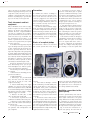
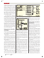
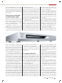
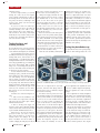
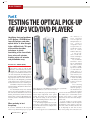
CMYK
M
MAAI NI TNETNEA NN CAE N C E
Part X
TESTING THE OPTICAL PICK-UP
OF MP3 VCD/DVD PLAYERS
Identifying front-end problems
in CD players, CDROM drives,
laser-disk players and other
optical drives is often thought
to be a difficult task. This part
of the article describes
techniques to check
functioning of the laser diode,
focus voice coil actuator,
tracking voice coil actuator
and photodiode array
GP CAPT. K.C. BHASIN (RETD)
I
f the player is able to read the disk
directory, even erratically, the tests described here are unnecessary (unless
you suspect an intermittent behaviour of
one of the sub-systems) as all major parts of
the laser pickup assembly must be functioning properly in order to do this. However,
there may be some marginally performing
components such as a weak laser diode or
shorted turns in the focus or tracking coil.
Sometimes a dirty lens results in symptoms that may be mistaken for much more
serious problems.
For intermittent faults, first carefully
inspect the pickup assembly for bad solder connections and hairline cracks in the
flexible printed cables. Interlock switches
may be dirty or wornout. Mechanical problems may result in intermittent behaviour
as well.
When and why to test
the pickup
If you have examined the RF test-point
with a scope and found a proper eye patELECTRONICS FOR YOU
APRIL 2004
the directory is
never displayed
even though the
disk spins at the correct
speed—or
overspeeds or does
not spin in the correct direction (clockwise, as viewed
from the label side).
3. The eye pattern is weak, distorted or missing at
the RF test-point.
Try to eliminate
alternative causes
before undertaking
these tests as there
is a chance of damage due to accidents
or electrostatic discharge. There is a
good chance that the
tests will only confirm that the pickup
is dead—not many
of the faults you will
be able to locate are
easy to fix.
The following
descriptions assume
that the pickup is
Fisher Electronics Slim-4000 vertical 4-CD stereo system with
still installed in the
digital AM/FM stereo tuner & tower speakers
player but selected
portions are disconnected when required.
tern, this indicates proper functioning of
This enables you to conveniently use the
all the major components of the optical
circuitry of the player to control certain
pickup. If, however, any of the following
functions for the ‘live’ laser diode and phoare observed, testing of the laser diode,
todiode tests.
focus and tracking actuators and/or phoIt is also possible to test the pick-up
todiode array is suggested:
in standalone condition, but this requires
1. The start-up sequence does not coman alternative power supply to drive the
plete due to obvious failure of the pickup
laser diode. Since the microcontroller will
to perform some action. For example, there
not be imposing its own will on those
is no attempt to focus.
parts of the pickup still connected to the
2. Focus appears to be established but
CMYK
MAINTENANCE
player, this may be preferable. Caution:
Whenever applying external power to any
component, totally disconnect it by unplugging or unsoldering (label each wire
if there is any ambiguity) to prevent damage to the circuitry on the logic board.
Tools, documents and test
equipment
Only a minimum of tools and test equipment are required for these testing techniques to be effective. An oscilloscope is
desirable. However, a digital multimeter
can work as a substitute as no high-frequency measurements are needed. We assume here that a scope is available. It is
also assumed that the sled drive, or the
drawer or spindle motors, are functional,
as their correct operation may be required
for some of the tests.
A schematic will help greatly. Depending on the design of the unit, you’ll be able
to infer enough about the front-end electronics to get away without one. The design of the components of the optical pickup
is usually similar among CD players from
different manufacturers, which makes the
tests relatively model-independent. What
may differ are polarities of photodiodes,
laser diodes, connector pinouts, etc. These
can usually be determined quite easily.
Despite the incredible precision of the
focus and tracking servos, you can perform meaningful tests without sophisticated or specialised test equipment.
The following tools and test equipment
are required:
1. Basic hand tools including jeweler’s
precision screwdrivers
2. Digital multimeter
3. Oscilloscope (for photodiode/RF
tests). For most of the tests, almost any
scope will do as long as it has a DCcoupled vertical amp.
4. A 0-5V variable DC power supply
(500 mA). You can use a fixed 5V supply
with a series adjustable resistor (100 ohms
for focus and tracking actuator testing, and
250 ohms for laser diode testing). A highly
regulated supply is not needed
5. Resistors: 22 ohms (1W), 5 ohms
(1W), 50 ohms and 1 mega-ohm
6. Assorted test clip leads and a few
centimetres of 25SWG solid hookup wire
7. IR detector circuit, infrared (IR) detector card or IR sensitive camcorder (for
laser diode tests)
8. Low-speed (1-10Hz) sweep or function generator with low-impedance output or amplifier
Precautions
To minimise the chances of damage to
the laser diode, which is extremely sensitive to static and excess current, leave its
connector plugged into the main board
and do not attempt to test the laser diode
with an analogue multimeter (which on
the low-ohms scale may exceed the current rating of the laser diode).
As with all modern solidstate equipment, preventing electrostatic discharges
to sensitive components is critical. An antistatic wrist strap is desirable. In any case,
work in an area where static charge buildup is minimised—not on a carpet prone
to static build-up. Touch the metal chassis first to discharge yourself.
Basics of an optical pickup
For information or music to be read off a
CD, several systems must work closely
3. Lens must be focused to within a
fraction of a micrometre (µm) of optimal
to produce a diffraction-limited spot. This
is less than 2 µm in diameter at the disk
‘pits’. The lens is actually positioned several millimetres from the disk surface and
is maintained at the correct distance
through optical feedback controlling the
lens position using the focus coil.
4. Lens must align to within a fraction
of a micrometre of the centre of the track.
Tracks on a CD are spaced 1.6 µm apart.
Tracking is maintained via optical feedback controlling the radial lens position
using the tracking coil (or the radial positioning unit on some rotary positioners).
If the behaviour while the CD player
is attempting to read the directory changes,
whether a disk is in place or not, and
there is no separate disk sensor, some or
all of these components are functioning
correctly. For example, many CD players
don’t attempt to rotate the spindle until
Sharp CD-BA250 mini component system with 3-disk rotary changer system
together:
1. Laser must be emitting a coherent
beam of sufficient power and stability. The
optical system must be clean and properly aligned. Laser power is maintained
constant via an optical feedback loop controlling the laser diode current. Therefore
a weak laser may not be salvageable as
the feedback loop may have done all that
is feasible.
2. Photodiode sensors must be functioning correctly for data recovery and focus and tracking feedback. A 3-beam pickup
has six segments: the central segments A-D
are used for focus and data recovery, and
the outer segments E and F are used for
tracking feedback. In a single-beam pickup,
segments E and F are absent.
proper focus has been established. Thus,
if the CD rotates when in place but the
bare spindle does not, it is likely that focus is being established successfully.
Identifying connections to the
optical pickup
In order to perform many of the tests described below, you have to locate the drive
and/or signal connections to the optical
pickup. While there are many variations in
the construction of optical pickups even
from the same manufacturer, they all need
to perform the same functions. So the internal components are usually quite similar.
Fig. 41 shows the connections for a
typical Sony pick-up. For laser diode asAPRIL 2004
ELECTRONICS FOR YOU
CMYK
MAINTENANCE
sembly and photodiode chip connections,
a single flex cable having 10 to 12 conductors is used. The actuator connections
may also be included on it or a separate
4-conductor flex cable may be used. The
signals may be identified on the circuit
board to which they attach, with designations as shown in the figure. The signals
A, C and B, D are usually shorted together near the connector as these are always used in pairs. The laser current testpoint, if present, is near the connections
for the laser diode assembly.
It is usually possible to identify most
of these connections with a strong light
and magnifying glass by tracing back from
the components on the optical block. The
locations of the laser diode assembly and
the photodiode array chip are usually easily identified. Some regulation and/or protection components may also be present.
There is often a pair of solder pads on
two adjacent traces. Short these pads by
applying a glob of solder using a grounded
soldering iron. This protects the laser diode from electrostatic or other damage during handling and testing, and a multimeter can be safely used to identify component connections and polarity.
Fig. 41: Connection diagram for a typical Sony pickup
beam and you do not see the red dot,
either the laser diode is dead or power is
not being applied by the control circuits.
Testing whether laser diode is
being powered
Testing the laser diode while
in the player
Fig. 42: IR detector circuit
Without a laser power meter, it is difficult
to fully verify laser functionality. However, determining that infrared is being
emitted provides a reasonable assurance
of laser operation.
For this test, you need an IR detector.
A simple IR detector circuit is shown in
Fig. 42. This unit is also useful for testing
of remote controls and other IR emitters.
However, you need to gain access to the
lens. This may require the removal of the
clamper assembly.
Once this is accomplished, prepare to
position the photodiode of the IR tester
within 3 mm of the lens. Plug the unit in
and turn it on. On portables, you need to
defeat the door interlock by using a toothpick or bit of cardboard. Some CD players have a disk-detection sensor separate
from the laser assembly. This needs to be
defeated for this test to work without a
CD in place. If it is a simple optical
sensor, a piece of black tape or paper
would suffice.
Once a CD is in place and the play
button is pressed, the laser must be powered. You can detect this in a darkened
room because there is usually a very faint
red light emission, which you can see as
a tiny red dot of light if you look at the
lens from a safe distance of at least 15 cm
(6 inches) at an oblique angle. Do not
look into the lens directly from above or
from very close as the invisible IR is much
stronger than the faint red emission and
potentially hazardous. If you see the faint
red light, power is being applied to the
laser diode.
With the laser lit, the lens should go
through a few focus-search cycles (typically, two to eight). While it is doing this,
position the IR detector above the lens. If
the laser is working, you will get a positive indication of IR in about a 30-degree
cone on either side of the lens. While you
have no way of knowing whether the
power output is correct, this is a reasonable indication of laser operation. Due to
the wide angle of the beam, the power
decreases rapidly with distance. So you
need to be very close to the lens for a
positive result.
If the lens moves smoothly in at least
one direction (up or down), the focus actuator is functioning.
If the IR detector does not pick up a
ELECTRONICS FOR YOU
APRIL 2004
If there is no indication of an IR emission
but the lens is moving up and down attempting to focus, the next step is to determine whether the laser diode is being
powered or is totally dead.
If you have a service manual, follow
the instructions given there for checking
the laser diode—usually by measuring a
voltage drop across a sensing resistor or
other test-point. If the reading is very low
or 0, a fault is likely in the driver or the
optical feedback circuitry. If the reading is
very high, the laser diode is likely to be
bad and the driver is unable to compensate for low or no emission.
Look for a test-point labeled ‘laser
power.’ Even if you don’t know what the
reading should be, anything other than 0
would be a good indication that the driver
is being enabled.
If you don’t have the service manual,
carefully measure across the laser diode
with a multimeter to determine whether
there is any voltage when it is supposed
to be active. A normal reading is 2 to 3 V.
For Sony and other similar pickups,
there is a chip capacitor across the laser
diode. The trick is in being able to attach
meter probes to these points without destroying everything!
The flex cable may also have a pair of
solder pads. To attach fine wires to these
for your multimeter, use a fine-point soldering iron—preferably grounded and temperature-controlled—to prevent damage.
Warning: For testing the laser diode,
use a digital multimeter with ESD protec-
CMYK
MAINTENANCE
tion to avoid damage to the laser diode.
Make all connections with power turned
off as the momentary glitch from attaching the probes and/or an accidental shortcircuit can easily burn up the laser diode
and other parts.
Testing the laser diode with
an external power supply
Consider the following only if there is no
indication of laser output while the laser
diode is connected to the player and you
do not have schematics or a service
manual to determine whether the laser
power circuits are functioning.
Typically, the current is in the 30100mA range at 1.7-2.5V. However, the
power curve is extremely non-linear. There
is a threshold below which there is no
output. For a diode rated at a threshold of
connecting the laser diode.
Slowly increase the current until you
get a beam. Use an IR detector for beam
detection. If you get the polarity backwards or are actually measuring across
the internal photodiode, the voltage across
the diode goes above 3 volts or is less
than 1V. Then, turn power off and reverse the leads. Some laser diodes get destroyed by a reverse voltage greater than
3V—the reverse voltage rating is listed in
the specification sheet.
Without a laser power meter, however,
you have no way of knowing when the
limit for safe beam power (for the laser
diode) is reached. For this test, increase
the current only until you get an indication on the IR detector or you see the red
dot. You are not trying to measure power,
just to see whether it works at all. A typical threshold is around 30 mA. Sometimes,
be an increase in the laser output power
beyond its normal range—which may
shorten its life substantially.
If the laser output power has decreased, there is probably nothing that can
be done as the feedback circuit is already
doing its bit and the adjustment will have
little effect. Thus, make sure the optics
are as clean as possible before you touch
the laser power.
The following will enable you to play
a disk, even if it has some problems with
noise or tracking: Put the oscilloscope
probe on the RF test point. While the disk
is playing, you should see the eye pattern. Mark the exact amplitude of the
peaks. Also note the playback quality, so
you can recognise if it changes.
While the correct voltage for the eye
pattern is not the same in all players, typical values are in the 1-2V range. If you
the operating current is marked on the
pickup. Do not exceed this current.
If you detect a beam and there was
none before, the problem is most likely in
the player’s control or power circuits, not
in the pick-up.
find it to be only a few hundred mV, there
is likely to be a problem. Caution: A weak
eye pattern can also be due to improper
focus bias adjustment. Check whether it
is an electronic problem. The laser power
may be normal.
Turn the laser power adjustment with
the player power switched-off to avoid the
possibility of electrical noise causing current spikes. Mark the exact position of the
laser power adjustment, so you can get
back to it if there is no effect or it makes
things worse.
Turn the control the slightest bit clockwise. Turn on the power and/or note the
eye pattern amplitude. If the laser diode
is not at the limit of its power, you should
see the amplitude change from what it
was. If it has decreased, try the other direction.
Note the playback quality. Has it
changed for the better? If not, laser power
is probably not the problem. If the amplitude of the eye pattern is unchanged, either you are turning the wrong control or
the laser is at its power limit—and it may
get damaged soon. Try the same test in
the counterclockwise direction if the am-
Philips ultra-slim DVD-video karaoke player
30 mA, the maximum operating current
may be as low as 40 mA. A sensing photodiode is built into the same case as the
laser diode to regulate beam power. It is
critical to the life of the laser diode that
under no circumstances is the safe current exceeded even for a microsecond.
Laser diodes are also extremely sensitive to electrostatic discharge, so take appropriate precautions. Also, don’t try to
test them with a volt-ohm-meter, which
could exceed their safe current rating on
the low-ohms scale. Even connecting the
test leads can blow the laser diode from
static. Always make or break power or test
connections with the player turned off.
Use a 0-5V DC linear supply with a 50ohm resistor in series with the diode; a
switching supply’s spikes may destroy the
laser diode. If you use a variable resistor,
make sure it is at its maximum resistance
when you start, so as to keep the current
under 20 mA. Keep in mind that a wall
wart (a small power-supply brick with integral male plug, designed to plug directly
into a wall outlet) rated at 5V may actually
put out 8V or more when unloaded, so
check the current into a short circuit before
Laser power adjustment
As mentioned earlier, the laser diode may
get destroyed when attempting to adjust
its output power. However, if you suspect
a weak laser as indicated by noisy playback or poor tracking performance, and
have eliminated all other possibilities such
as servo adjustments, attempt one of the
procedures described here.
What adjusting the laser power probably does isn’t compensating for a decrease
in laser diode intensity, but rather a
buildup of dust and other junk on the
optics (possibly internal and inaccessible),
which reduces the beam intensity at the
CD and the return beam intensity even
more. There is a subtle difference as the
optical output of the laser diode itself is
feedback-controlled and shouldn’t drift
much and the result of an adjustment will
APRIL 2004
ELECTRONICS FOR YOU
CMYK
MAINTENANCE
plitude decreases.
If there is improvement, you can risk
leaving the control at the new higherpower setting, realising that you may be
shortening the life of the laser diode. Do
not push your luck by continuing to turn
up the power, unless you have tried all
other alternatives.
If you do not have an oscilloscope,
you can still try the above procedure by
carefully listening to the audio to determine whether there is any change. It’s a
little bit riskier: The laser power adjustment may be very sensitive and you have
no direct way of knowing how much you
have increased the setting.
Testing the focus and
tracking actuators
If your CD player has a rotary positioner,
there may be no separate tracking coil as
coarse and fine tracking may be combined.
Typical linkages between the lens/coil
assembly and the body of the pickup are a
sliding shaft (focus) and rotation on the
shaft (tracking), or a hinged hinge. With a
sliding shaft and rotation on the shaft, the
slide can get gummed up, preventing reliable focus and tracking. With a hinged
hinge, one or both hinges may break, as
these are often made of thin, flexible plastic. Repair is not really possible.
To test whether the lens is focusing or
tracking properly, perform the following:
First, identify the cable leading to the focus and tracking voice-coil mechanism.
This is usually a 4-conductor cable separate from the data and laser cable (at least
at the pickup end). Disconnect it from the
main board before testing. Using a digital
multimeter, you can locate the pair of coils
with very low resistance (a few ohms).
One of these is focus coil and the other is
tracking coil.
Construct one of the following test circuits:
1. Take a 4-5V DC eliminator. Connect a variac at its output and a 22-ohm,
1W resistor in series with a pair of 50cm,
24SWG insulated wires.
2. Take a 5V DC power supply connected in series with a 100-ohm variable
resistor and 22-ohm, 1W fixed resistor with
a pair of 50cm, 24SWG insulated wires.
Gain access to the lens for visual inspection. For this, you need to eject the
disk, open the drawer or, in some cases,
actually remove the clamper. In a portable or boombox, the lens is readily accessible. Unplug the CD player from the
ELECTRONICS FOR YOU
APRIL 2004
AC socket or remove the batteries, as you
don’t need to use its internal power.
With power supply switched off or the
variac turned all the way down, connect
the 24SWG leads to one of the located
pairs of coils. Now, turn on the power
and slowly adjust the variac or rheostat
while watching the lens. If you are connected to the focus coil, you’ll see the
lens moving up and down. If you are connected to tracking coil, you’ll see it moving from side to side.
If there is no motion, turn off the power
supply, reverse the polarity and try again.
For a typical pick-up, the 4-5V power supply and a minimum of 22-ohm resistor
should cause the lens to move through the
entire range of motion up and down or side
to side, as appropriate. Once you have
exercised the first coil, switch connections
and repeat for the other. If the motion is
jerky, the lens assembly is dirty.
Clean the lens assembly carefully first
tracking and increase the needed servo
driver power. A CD player that is overly
sensitive to slight disk defects even after
all the proper adjustments have been performed may conceivably be a result of
this type of fault. An additional symptom
may be an unusually hot servo driver IC.
However, many of these ICs run hot normally, so don’t worry unduly as the possibility of shorted turns is really quite remote.
An intermittent may only show up during dynamic operation, with certain CDs
or other peculiar circumstances. The intermittent could be at the solder connections or the fine, printed ribbon cable that
connects the moving lens assembly to the
remainder of the pickup.
Testing the photodiode array
The photodiode array in an optical pickup
consists of an IC with typically four or six
Panasonic SC-AK410S Nitrix series mini system with 5-CD changer and 3-way speakers
with a bit of compressed air (not highpressure) and then with Q-tips and isopropyl alcohol. Do not lubricate. Repeat
the tests after cleaning.
If both the tests are positive, the focus
and tracking actuators are functioning. If
either you were unable to locate both pairs
of coils or one or both actuators did not
move, you have located a problem. An
open coil can be due to a cable problem or
a break in the coil. If the break is right at
the solder connections, which are usually
visible once the plastic protective shroud is
popped off, you can repair it. However,
this requires a great deal of manual dexterity and patience, as the wire is really fine.
Shorted turns in the fine coils or an
intermittent are still possible. Shorted turns
reduce the frequency response of the
servo, reduce the reliability of focus or
detector segments. Four segments are used
in the less common single-beam pickups,
while six segments are used in 3-beam
pickups.
These segments are usually designated
A through F. A, B, C and D form the main
detector, which is used for both focusing
and data recovery. Generally, segments E
and F are used in a 3-beam pickup for
fine tracking feedback. The same has been
assumed in the following discussion.
All the six photodiodes are connected
to a common point, which, during operation, has a DC bias voltage of around 5V.
If the photodiodes are connected in common-anode configuration, it will be negative. If common-cathode configuration is
used, it will be positive. The reason is
that the photodiodes need to be reverse
biased for normal operation. The outputs
CMYK
MAINTENANCE
of the photodiodes feed several operational
amplifiers, which are set up to amplify
the current from the photodiodes. The normal connections may be at virtual ground
potential or these may feed into large-value
resistors.
The connector to the photodiode array is usually separate and typically has
at least eight wires—comprising connections to photodiodes A through F, ground
and bias voltage.
You need to identify the wires. First,
locate the ground using the ohmmeter.
Then locate the bias—it usually goes to a
low-value resistor and then to the supply.
Another way to identify the bias wire is
to turn on the player and measure each of
the possibilities: The bias is the highest or
the lowest, with no noise or ripple. It is
powered all the time.
Now identify the photodiode segments.
Very often the connections are marked on
the circuit board; for example, there may
be several labeled test-points designated
junction drop in the forward direction and
very high resistance in the reverse direction. If you use a digital multimeter in
diode testing mode, the junction drop is
typically 0.7 V. There may be a very slight
difference between the readings for segments A to D and those for E and F.
An initial test of photodiode response
can be made by using an external light
source (a flashlight or other incandescent
bulb or IR remote control) to illuminate
the lens directly from above. With the multimeter connected to reverse-bias each diode segment, illuminate the lens. The resistance reading should drop, possibly dramatically. Segments A to D should show
reasonably similar sensitivities but these
may differ for segments E and F (which
should be similar to each other).
Similarly, with the photodiode connections restored to normal, you can use an
oscilloscope to monitor the RF test point. A
source of IR directed towards the lens from
above may result in a detectable change in
photodiode array.
Any unusual reading such as a significantly lower resistance for one of the diodes, a short or open diode, a short between diodes or variations in sensitivities
is an indication of a problem. This is somewhat unlikely, though bad solder connections or breaks in the flexible cables are
not ruled out.
A defect found in the photodiode array usually means that the laser pickup is
not salvageable with reasonable effort.
Even if you could locate a replacement
photodiode array, aligning and soldering
the surface mount package is quite a challenge without the factory jigs.
Assuming that these tests don’t turn up
anything, the next step is to verify that the
photodiodes are picking up an optical signal and evaluate the relative strengths of
each segment using the laser diode, optical
system and disk combination. For these
tests to confirm proper operation, the optical alignment must also be correct.
the signal, but only when the photodiode
array is properly biased. This signal may
be present all the time the CD player is
turned on or only when the player is trying
to focus or perform some other operation.
With an IR remote, you should actually see
the pulsed signal for each key-code. On a
typical Sony CD player, you could get about
0.1V signal at the RF test point using a VCR
remote control as an IR source.
However, even on a functional pickup, due to the nature of the optics, these
responses may be very weak or undetectable. Thus, failure of either of the above
tests is not a strong evidence of a bad
For the tests using the internal laser
diode, you need to set up either an adjustable focus with continuously rotating
spindle or a stationary spindle but sweeping focus. The latter is more straightforward but requires the optional signal generator for best results. In each case, the
objective is to cause the lens-disk distance
to sweep through perfect focus without
requiring the focus servo loop to be closed.
This results in a signal that includes the
point of maximum signal amplitude on a
periodic basis. Alternative methods may
be used to accomplish the same purpose.
Both techniques require the use of an ad-
Sony DVP-NS700P DVD player
A+C, B+D, E and F. Since the A and C
segments and B and D segments are usually shorted together on the circuit board,
this provides all the information needed
to identify the photodiode connections. It
is not important to distinguish between A
and C, or B and D for the following tests,
though you will want to be able to separate them.
With power off, there is essentially no
light on the photodiode array. Unplug the
photodiode connector from the main
board. Using your ohmmeter, test each
diode for open and short, as you would
test any signal diode. There should be a
APRIL 2004
ELECTRONICS FOR YOU
CMYK
MAINTENANCE
justable power supply.
The test set-ups are described below:
1. Adjustable focus with continuously
rotating spindle. For the spindle motor,
you need a 1.5V battery or power supply
with a suitable series resistor to cause the
spindle to turn at approximately 1-2 Hz
(revolutions per second). (Warning: Disconnect the motor from the main board.)
The unavoidable wobble of any disk is
essential in this case and sweeps the focus distance by more than enough to cover
the entire focus range of interest.
It has been assumed that the spindle
is driven by a conventional permanentmagnet DC motor. If it is a brushless DC
motor, some of the control electronics may
be external to the motor and you will not
be able to provide a DC voltage to get it
rotate. If this is the case, you must use a
stationary spindle but sweeping focus.
2. Stationary spindle but sweeping
focus. This is a better method but requires
a signal generator for the easiest use. You
can do this by hand using a variac or
rheostat. A better method is to use a 110Hz sinusoidal or triangular wave from
a low-frequency signal generator with a
low-impedance output or feeding an emitter follower or audio amplifier to boost
the current. This signal is then fed into
the coil along with the focus offset derived from the power supply.
It is possible to dispense with these test
set-ups and just use the normal focus search
of the CD player itself to provide the sweep.
However, since you will be interfering with
the proper feedback by removing selected
sensors, there is no assurance as to what
the microcontroller does. Therefore breaking the feedback loop, as we are doing, is
preferred. However, if the CD player appears to make many attempt at focus, this
may be worth a trial.
You may also need a new disk—preferably one you do not care much about—
as it may get scratched due to opening
the drawer accidentally or doing something equally undesirable while the disk
is still rotating.
Locate a 1-mega-ohm resistor and securely fasten it to a ground near the photodiode connector. Put the scope probe
on the other end with its ground clipped
to the same ground point as the resistor.
Bend the free lead of the resistor completely over so that it is able to hold the
end of a wire like a mini-clip lead.
Mark down exactly how the connector
is wired so that as you remove individual
wires, you are able to get them back in the
ELECTRONICS FOR YOU
APRIL 2004
offset from your power
supply.
You may not need
to touch the settings for
testing the remaining
photodiode segments.
Repeat the testing
procedure for each of
the photodiodes A
through F. All should
produce fairly similar
signals, say, within 20
per cent of one another
in amplitude. If A, B,
C and D, or E and F,
Fisher Electronics’ Slim-1400 digital AM/FM/CD-R/RW
differ from one another
executive slim audio system
by more than, say, 20
proper spot. Presumably, you have already
per cent, there is a serious optical alignmade a diagram of the photodiode connecment problem in the pick-up. Else, the
tor wiring. Component players often have
photodiode array may be bad. Partially
connectors with individually removable
shorted photodiode segments are also possocket pins. A fine jeweller’s screwdriver
sible. In this case, the outputs will not be
or paper clip may prove handy in removing
independent. Loading one segment’s outthese one at a time.
put with a resistor may affect the output
Turn on the power supply and adjust
of other segments.
the focus to about mid-range. Start the
Such a discrepancy in photodiodes A to
spindle rotating or turn on the signal genD prevents the establishment of a proper,
erator to provide a small sweep—about
stable lens position at the optimal focal
1/10 Vp-p, as measured on the coil.
distance. This prevents the formation of a
proper eye pattern and subsequent data
recovery. A significant difference between
Making the photodiode
E and F (beyond the adjustment range of
measurements
the tracking or E-F balance control) preRemove the wire corresponding to the phovents proper tracking. However, the signal
todiode to be tested (say, A) from the
amplitudes from photodiodes A through D
connector but leave the connector itself
and E and F may differ as photodiodes A
plugged into the main board. Set the scope
through D operate off the main beam and E
for 1V/div. vertical deflection in slow, freeand F operate off the first-order diffracted
running sweep mode.
beams (which are weaker). As with the
Clip the A wire into the resistor. Now,
basic photodiode tests above, a failure here
turn on power to the CD player. While
usually requires replacement of the entire
the player attempts to focus, slowly adoptical assembly.
just the focus voltage while observing the
As noted, if the pick-up’s optical alignscope. As you approach proper focus, you
ment is way off, there could be significant
will see the signal increase greatly (dedifferences in photodiode responses. On
pending on the polarity), pass through a
component-type units, it is unlikely that
maximum and then decrease. Depending
the optical alignment shifts on its own.
on the design of the CD player, you may
Portables dropped down accidently or auneed to turn it off and on several times
tomotive units subject to constant bumps
before you locate the signal, since the
and vibration could have alignment probmicrocontroller may give up pretty quickly
lems, however. If this eventually results
with no focus or tracking coil servos (as
in improved uniformity of the photodiode
you’ve disconnected the actuators). The
response, alignment could be the probservice manual may guide you on how to
lem. If you can, more or less equalise the
force the laser to be powered all the time.
response, reconnect the servos and attempt
Leave the focus set near the middle of the
to get an eye pattern. If you can optimise
region of high signal.
the eye pattern stability and amplitude usIf you use the signal generator to pering the optical alignment adjustments and
form the focus sweep, you need to
servo adjustments, you would have
optimise the amplitude of the signal by
achieved proper alignment.
adjusting the signal generator output and
To be continued...