1
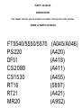
RICOH FT5540/5550/5570
SERVICE MANUAL
RICOH COMPANY, LTD.
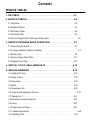
Table of Contents
OVERALL MACHINE INFORMATION
1. SPECIFICATIONS . . . . . . . . . . . . . . . . . . . . . . . . . . . . . . . . . . . . . . . 1-1
2. GUIDE TO COMPONENTS . . . . . . . . . . . . . . . . . . . . . . . . . . . . . . . . 1-4
2.1 INTERNAL/EXTERNAL . . . . . . . . . . . . . . . . . . . . . . . . . . . . . . . . . . . . . . . . . . . . . . 1-4
2.2 OPERATION PANEL . . . . . . . . . . . . . . . . . . . . . . . . . . . . . . . . . . . . . . . . . . . . . . . . . 1-6
2.3 INDICATOR SCREEN . . . . . . . . . . . . . . . . . . . . . . . . . . . . . . . . . . . . . . . . . . . . . . . . 1-8
2.4 GUIDANCE DISPLAY . . . . . . . . . . . . . . . . . . . . . . . . . . . . . . . . . . . . . . . . . . . . . . . . 1-9
3. COPY PROCESSES AROUND THE DRUM . . . . . . . . . . . . . . . . . . 1-10
4. COPY CYCLE . . . . . . . . . . . . . . . . . . . . . . . . . . . . . . . . . . . . . . . . 1-12
5. PAPER PATH . . . . . . . . . . . . . . . . . . . . . . . . . . . . . . . . . . . . . . . . . 1-13
6. DRIVE LAYOUT
. . . . . . . . . . . . . . . . . . . . . . . . . . . . . . . . . . . . . . . 1-16
7. MECHANICAL COMPONENT LAYOUT . . . . . . . . . . . . . . . . . . . . . 1-17
8. ELECTRICAL COMPONENT LAYOUT . . . . . . . . . . . . . . . . . . . . . 1-18
9. ELECTRICAL COMPONENT DESCRIPTIONS . . . . . . . . . . . . . . . 1-23
10. OVERALL MACHINE CONTROL . . . . . . . . . . . . . . . . . . . . . . . . . 1-28
11. AC AND DC POWER DISTRIBUTION . . . . . . . . . . . . . . . . . . . . . 1-29
DETAILED SECTION DESCRIPTIONS
1. DRUM . . . . . . . . . . . . . . . . . . . . . . . . . . . . . . . . . . . . . . . . . . . . . . . . 2-1
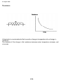
1.1 SELENIUM DRUM CHARACTERISTICS . . . . . . . . . . . . . . . . . . . . . . . . . . . . . . . . . 2-1
1.2 HANDLING THE DRUM . . . . . . . . . . . . . . . . . . . . . . . . . . . . . . . . . . . . . . . . . . . . . . 2-1
1.3 DRUM HEATER CONTROL . . . . . . . . . . . . . . . . . . . . . . . . . . . . . . . . . . . . . . . . . . 2-3
2. DRUM CHARGE . . . . . . . . . . . . . . . . . . . . . . . . . . . . . . . . . . . . . . . . 2-4
2.1 OVERVIEW . . . . . . . . . . . . . . . . . . . . . . . . . . . . . . . . . . . . . . . . . . . . . . . . . . . . . . . . 2-4
2.2 WIRE CLEANER . . . . . . . . . . . . . . . . . . . . . . . . . . . . . . . . . . . . . . . . . . . . . . . . . . . . 2-5
2.3 CHARGE CORONA POWER PACK . . . . . . . . . . . . . . . . . . . . . . . . . . . . . . . . . . . . . 2-6
3. OPTICS . . . . . . . . . . . . . . . . . . . . . . . . . . . . . . . . . . . . . . . . . . . . . . 2-7
3.1 OVERVIEW . . . . . . . . . . . . . . . . . . . . . . . . . . . . . . . . . . . . . . . . . . . . . . . . . . . . . . . . 2-7
3.2 EXPOSURE LAMP CONTROL . . . . . . . . . . . . . . . . . . . . . . . . . . . . . . . . . . . . . . . . . 2-9
3.3 SCANNER DRIVE . . . . . . . . . . . . . . . . . . . . . . . . . . . . . . . . . . . . . . . . . . . . . . . . . . 2-10
3.4 SCANNER MOTOR CONTROL . . . . . . . . . . . . . . . . . . . . . . . . . . . . . . . . . . . . . . . 2-11
3.5 LENS/MIRROR POSlTIONING . . . . . . . . . . . . . . . . . . . . . . . . . . . . . . . . . . . . . . . . 2-12
3.6 FOURTH AND FlFTH MlRROR ASSEMBLY . . . . . . . . . . . . . . . . . . . . . . . . . . . . . . 2-15
3.7 ORlGINAL SIZE DETECTION . . . . . . . . . . . . . . . . . . . . . . . . . . . . . . . . . . . . . . . . . 2-17
3.8 RELATED SERVICE CALL CONDITIONS . . . . . . . . . . . . . . . . . . . . . . . . . . . . . . . . 2-17
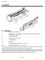
4. ERASE . . . . . . . . . . . . . . . . . . . . . . . . . . . . . . . . . . . . . . . . . . . . . . . 2-22
4.1 OVERVIEW . . . . . . . . . . . . . . . . . . . . . . . . . . . . . . . . . . . . . . . . . . . . . . . . . . . . . . . 2-22
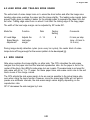
4.2 LEAD EDGE AND TRAILING EDGE ERASE . . . . . . . . . . . . . . . . . . . . . . . . . . . . . 2-23
4.3 SlDE ERASE . . . . . . . . . . . . . . . . . . . . . . . . . . . . . . . . . . . . . . . . . . . . . . . . . . . . . . 2-23
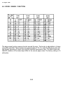
4.4 EDGE ERASE FUNCTION . . . . . . . . . . . . . . . . . . . . . . . . . . . . . . . . . . . . . . . . . . . 2-24
4.5 ERASE LAMP CIRCUIT . . . . . . . . . . . . . . . . . . . . . . . . . . . . . . . . . . . . . . . . . . . . . . 2-25
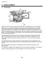
5. DEVELOPMENT . . . . . . . . . . . . . . . . . . . . . . . . . . . . . . . . . . . . . . . 2-26
5.1 OVERVlEW . . . . . . . . . . . . . . . . . . . . . . . . . . . . . . . . . . . . . . . . . . . . . . . . . . . . . . . 2-26
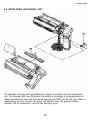
5.2 DEVELOPER EXCHANGE UNIT . . . . . . . . . . . . . . . . . . . . . . . . . . . . . . . . . . . . . . . 2-27
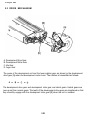
5.3 DRIVE MECHANlSM . . . . . . . . . . . . . . . . . . . . . . . . . . . . . . . . . . . . . . . . . . . . . . . . 2-28
5.4 CROSSMlXlNG . . . . . . . . . . . . . . . . . . . . . . . . . . . . . . . . . . . . . . . . . . . . . . . . . . . . 2-29
5.5 IMAGE DENSlTY CONTROL . . . . . . . . . . . . . . . . . . . . . . . . . . . . . . . . . . . . . . . . . 2-30
5.6 BIAS CONTROL CIRCUIT . . . . . . . . . . . . . . . . . . . . . . . . . . . . . . . . . . . . . . . . . . . . 2-36
5.7 RELATED SERVICE CALL CONDlTIONS . . . . . . . . . . . . . . . . . . . . . . . . . . . . . . . . 2-37
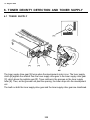
6. TONER DENSITY DETECTION AND TONER SUPPLY . . . . . . . . . 2-38
6.1 TONER SUPPLY . . . . . . . . . . . . . . . . . . . . . . . . . . . . . . . . . . . . . . . . . . . . . . . . . . . 2-38
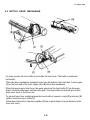
6.2 BOTTLE DRIVE MECHANISM . . . . . . . . . . . . . . . . . . . . . . . . . . . . . . . . . . . . . . . . 2-39
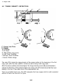
6.3 TONER DENSITY DETECTION . . . . . . . . . . . . . . . . . . . . . . . . . . . . . . . . . . . . . . . 2-40
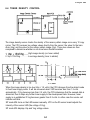
6.4 TONER DENSITY CONTROL . . . . . . . . . . . . . . . . . . . . . . . . . . . . . . . . . . . . . . . . . 2-41
6.5 TONER SUPPLY AMOUNT . . . . . . . . . . . . . . . . . . . . . . . . . . . . . . . . . . . . . . . . . . . 2-42
6.6 TONER END DETECTION . . . . . . . . . . . . . . . . . . . . . . . . . . . . . . . . . . . . . . . . . . . 2-44
6.7 TONER OVERFLOW SENSOR CIRCUIT . . . . . . . . . . . . . . . . . . . . . . . . . . . . . . . . 2-45
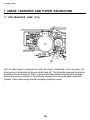
7. lMAGE TRANSFER AND PAPER SEPARATION . . . . . . . . . . . . . . 2-46
7.1 PRE-TRANSFER LAMP (PTL) . . . . . . . . . . . . . . . . . . . . . . . . . . . . . . . . . . . . . . . . . 2-46
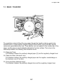
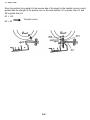
7.2 IMAGE TRANSFER . . . . . . . . . . . . . . . . . . . . . . . . . . . . . . . . . . . . . . . . . . . . . . . . . 2-47
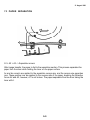
7.3 PAPER SEPARATION . . . . . . . . . . . . . . . . . . . . . . . . . . . . . . . . . . . . . . . . . . . . . . . 2-49
7.4 TRANSFER/SEPARATION CORONA POWER PACK . . . . . . . . . . . . . . . . . . . . . . 2-50
7.5 PICK-OFF MECHANISM . . . . . . . . . . . . . . . . . . . . . . . . . . . . . . . . . . . . . . . . . . . . . 2-52
7.6 PICK-OFF TIMING . . . . . . . . . . . . . . . . . . . . . . . . . . . . . . . . . . . . . . . . . . . . . . . . . . 2-53
7.7 PRE-TRANSFER LAMP AND QUENCHING LAMP CIRCUIT . . . . . . . . . . . . . . . . . 2-54
8. DRUM CLEANING . . . . . . . . . . . . . . . . . . . . . . . . . . . . . . . . . . . . . 2-55
8.1 OPERATION . . . . . . . . . . . . . . . . . . . . . . . . . . . . . . . . . . . . . . . . . . . . . . . . . . . . . . 2-55
8.2 PRE-CLEANING CORONA AND BIAS ROLLER . . . . . . . . . . . . . . . . . . . . . . . . . . 2-56
8.3 DRlVE MECHANISM . . . . . . . . . . . . . . . . . . . . . . . . . . . . . . . . . . . . . . . . . . . . . . . . 2-57
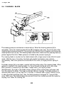
8.4 CLEANING BLADE . . . . . . . . . . . . . . . . . . . . . . . . . . . . . . . . . . . . . . . . . . . . . . . . . 2-58
8.5 CLEANING SOLENOID CIRCUIT . . . . . . . . . . . . . . . . . . . . . . . . . . . . . . . . . . . . . . 2-59
8.6 PRE-CLEANING CORONA ClRCUIT . . . . . . . . . . . . . . . . . . . . . . . . . . . . . . . . . . . 2-60
9. QUENCHING . . . . . . . . . . . . . . . . . . . . . . . . . . . . . . . . . . . . . . . . . . 2-61
9.1 OPERATION . . . . . . . . . . . . . . . . . . . . . . . . . . . . . . . . . . . . . . . . . . . . . . . . . . . . . . 2-61
9.2 PRE-QUENCHING CORONA CIRCUIT . . . . . . . . . . . . . . . . . . . . . . . . . . . . . . . . . 2-62
10. PAPER FEED . . . . . . . . . . . . . . . . . . . . . . . . . . . . . . . . . . . . . . . . . 2-63
10.1 OVERVIEW . . . . . . . . . . . . . . . . . . . . . . . . . . . . . . . . . . . . . . . . . . . . . . . . . . . . . . 2-63
10.2 LIFT MECHANISM AND PAPER END DETECTION . . . . . . . . . . . . . . . . . . . . . . 2-64
10.3 ROLLER FUNCTION . . . . . . . . . . . . . . . . . . . . . . . . . . . . . . . . . . . . . . . . . . . . . . . 2-66
10.4 SLIP CLUTCH MECHANISM . . . . . . . . . . . . . . . . . . . . . . . . . . . . . . . . . . . . . . . . 2-68
10.5 PAPER FEED DRIVE . . . . . . . . . . . . . . . . . . . . . . . . . . . . . . . . . . . . . . . . . . . . . . . 2-69
10.7 RELAY FEED AND REGISTRATION . . . . . . . . . . . . . . . . . . . . . . . . . . . . . . . . . . 2-72
10.8 PAPER SIZE SENSORS . . . . . . . . . . . . . . . . . . . . . . . . . . . . . . . . . . . . . . . . . . . . 2-74
10.9 LIFT MOTOR CONTROL AND PAPER END DETECTION . . . . . . . . . . . . . . . . . . 2-75
11. PAPER TRANSPORT . . . . . . . . . . . . . . . . . . . . . . . . . . . . . . . . . . 2-77
11.1 OVERVIEW . . . . . . . . . . . . . . . . . . . . . . . . . . . . . . . . . . . . . . . . . . . . . . . . . . . . . . 2-77
11.2 TRANSPORT UNIT RELEASE MECHANISM . . . . . . . . . . . . . . . . . . . . . . . . . . . . 2-78
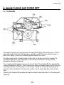
12. lMAGE FUSING AND PAPER EXIT . . . . . . . . . . . . . . . . . . . . . . . 2-79
12.1 OVERVIEW . . . . . . . . . . . . . . . . . . . . . . . . . . . . . . . . . . . . . . . . . . . . . . . . . . . . . . 2-79
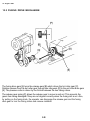
12.2 FUSING DRIVE MECHANISM . . . . . . . . . . . . . . . . . . . . . . . . . . . . . . . . . . . . . . . 2-80
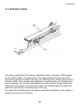
12.3 ENTRANCE GUIDE . . . . . . . . . . . . . . . . . . . . . . . . . . . . . . . . . . . . . . . . . . . . . . . . 2-81
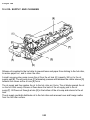
12.4 OIL SUPPLY AND CLEANING . . . . . . . . . . . . . . . . . . . . . . . . . . . . . . . . . . . . . . . 2-82
12.5 OIL END SENSOR . . . . . . . . . . . . . . . . . . . . . . . . . . . . . . . . . . . . . . . . . . . . . . . . 2-83
12.6 FUSING EXIT ASSEMBLY . . . . . . . . . . . . . . . . . . . . . . . . . . . . . . . . . . . . . . . . . . 2-84
12.7 FUSING CONTROL . . . . . . . . . . . . . . . . . . . . . . . . . . . . . . . . . . . . . . . . . . . . . . . . 2-85
12.8 SERVICE CALL CONDITIONS . . . . . . . . . . . . . . . . . . . . . . . . . . . . . . . . . . . . . . . 2-88
13. PAPER EXIT . . . . . . . . . . . . . . . . . . . . . . . . . . . . . . . . . . . . . . . . . 2-90
13,1 OVERVIEW . . . . . . . . . . . . . . . . . . . . . . . . . . . . . . . . . . . . . . . . . . . . . . . . . . . . . . 2-90
13.2 EXIT ROLLER DRIVE MECHANISM . . . . . . . . . . . . . . . . . . . . . . . . . . . . . . . . . . 2-91
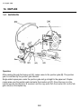
14. DUPLEX . . . . . . . . . . . . . . . . . . . . . . . . . . . . . . . . . . . . . . . . . . . . . 2-92
14.1 INVERSION . . . . . . . . . . . . . . . . . . . . . . . . . . . . . . . . . . . . . . . . . . . . . . . . . . . . . 2-92
14.2 DUPLEX TRANSPORT . . . . . . . . . . . . . . . . . . . . . . . . . . . . . . . . . . . . . . . . . . . . . 2-96
14.3 DUPLEX STACKING . . . . . . . . . . . . . . . . . . . . . . . . . . . . . . . . . . . . . . . . . . . . . . . 2-99
14.4 DUPLEX TRAY SENSORS . . . . . . . . . . . . . . . . . . . . . . . . . . . . . . . . . . . . . . . . . 2-103
14.5 DUPLEX PAPER FEED . . . . . . . . . . . . . . . . . . . . . . . . . . . . . . . . . . . . . . . . . . . . 2-104
14.6 RELATED SERVICE CALL CONDlTIONS . . . . . . . . . . . . . . . . . . . . . . . . . . . . . . 2-107
15. OTHER CIRCUITS . . . . . . . . . . . . . . . . . . . . . . . . . . . . . . . . . . . 2-108
15.1 DC POWER DISTRIBUTION . . . . . . . . . . . . . . . . . . . . . . . . . . . . . . . . . . . . . . . . 2-108
15.2 SAFETY SWITCH CIRCUITS . . . . . . . . . . . . . . . . . . . . . . . . . . . . . . . . . . . . . . . . 2-109
15.3 AC COMPONENT CONTROL . . . . . . . . . . . . . . . . . . . . . . . . . . . . . . . . . . . . . . . . 2-110
15.4 CORONA CLEANER MOTORS . . . . . . . . . . . . . . . . . . . . . . . . . . . . . . . . . . . . . . 2-111
15.5 PULSE GENERATOR . . . . . . . . . . . . . . . . . . . . . . . . . . . . . . . . . . . . . . . . . . . . . 2-112
15.6 MAGNETIC CLUTCH AND SOLENOID CONTROL . . . . . . . . . . . . . . . . . . . . . . 2-113
15.7 SENSOR OPERATION . . . . . . . . . . . . . . . . . . . . . . . . . . . . . . . . . . . . . . . . . . . . 2-114
15.8 COUNTER CIRCUITS . . . . . . . . . . . . . . . . . . . . . . . . . . . . . . . . . . . . . . . . . . . . . 2-117
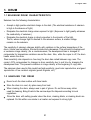
INSTALLATION
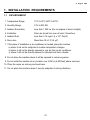
1. INSTALLATION REQUIREMENTS . . . . . . . . . . . . . . . . . . . . . . . . . . 3-1
1.1 ENVIRONMENT . . . . . . . . . . . . . . . . . . . . . . . . . . . . . . . . . . . . . . . . . . . . . . . . . . . . . 3-1
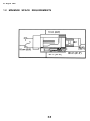
1.2 MlNlMUM SPACE REQUlREMENTS . . . . . . . . . . . . . . . . . . . . . . . . . . . . . . . . . . . . 3-2
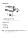
1.3 MACHINE LEVEL . . . . . . . . . . . . . . . . . . . . . . . . . . . . . . . . . . . . . . . . . . . . . . . . . . . 3-3
1.4 POWER SOURCE . . . . . . . . . . . . . . . . . . . . . . . . . . . . . . . . . . . . . . . . . . . . . . . . . . . 3-3
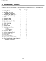
2. ACCESSORY CHECK . . . . . . . . . . . . . . . . . . . . . . . . . . . . . . . . . . . . 3-4
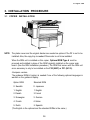
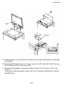
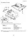
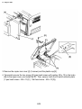
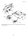
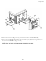
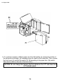
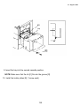
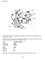
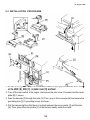
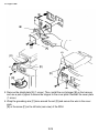
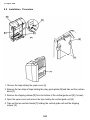
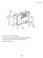
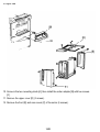
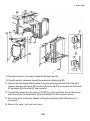
3. INSTALLATION PROCEDURE . . . . . . . . . . . . . . . . . . . . . . . . . . . . . 3-5
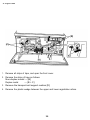
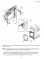
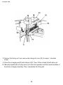
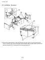
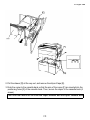
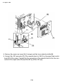
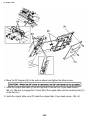
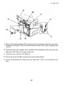
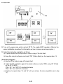
3.1 COPIER INSTALLATION . . . . . . . . . . . . . . . . . . . . . . . . . . . . . . . . . . . . . . . . . . . . . . 3-5
3.2 CASSETTE MODIFICATION . . . . . . . . . . . . . . . . . . . . . . . . . . . . . . . . . . . . . . . . . . 3-15
3.3 KEY COUNTER HOLDER INSTALLATION . . . . . . . . . . . . . . . . . . . . . . . . . . . . . . . 3-16
SERVICE TABLES
2. SERVICE TABLES . . . . . . . . . . . . . . . . . . . . . . . . . . . . . . . . . . . . . . . 4-4
2.1 Test Points . . . . . . . . . . . . . . . . . . . . . . . . . . . . . . . . . . . . . . . . . . . . . . . . . . . . . . . . . 4-4
2.2 Variable Resistors . . . . . . . . . . . . . . . . . . . . . . . . . . . . . . . . . . . . . . . . . . . . . . . . . . . 4-4
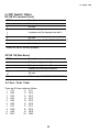
2.3 DIP SwitchTables . . . . . . . . . . . . . . . . . . . . . . . . . . . . . . . . . . . . . . . . . . . . . . . . . . . 4-5
2.4 User Code Table . . . . . . . . . . . . . . . . . . . . . . . . . . . . . . . . . . . . . . . . . . . . . . . . . . . . 4-5
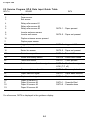
2.5 Service Program SP-8 Data lnput Guide Table . . . . . . . . . . . . . . . . . . . . . . . . . . . . 4-6
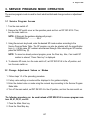
3. SERVICE PROGRAM MODE OPERATION . . . . . . . . . . . . . . . . . . . 4-7
3.1 Service Program Access . . . . . . . . . . . . . . . . . . . . . . . . . . . . . . . . . . . . . . . . . . . . . . 4-7
3.2 Change Adjustment Values or Modes . . . . . . . . . . . . . . . . . . . . . . . . . . . . . . . . . . . 4-7
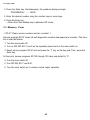
3.3 Memory Clear . . . . . . . . . . . . . . . . . . . . . . . . . . . . . . . . . . . . . . . . . . . . . . . . . . . . . . 4-8
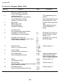
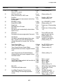
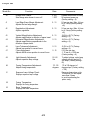
3.4 Service Program Mode Table . . . . . . . . . . . . . . . . . . . . . . . . . . . . . . . . . . . . . . . . . 4-10
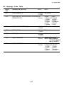
3.5 Language Code Table . . . . . . . . . . . . . . . . . . . . . . . . . . . . . . . . . . . . . . . . . . . . . . . 4-17
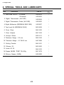
4. SPECIAL TOOLS AND LUBRICANTS . . . . . . . . . . . . . . . . . . . . . . 4-18
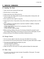
5. SERVICE REMARKS . . . . . . . . . . . . . . . . . . . . . . . . . . . . . . . . . . . . 4-19
5.1 Handling The Drum . . . . . . . . . . . . . . . . . . . . . . . . . . . . . . . . . . . . . . . . . . . . . . . . . 4-19
5.2 Charge Corona . . . . . . . . . . . . . . . . . . . . . . . . . . . . . . . . . . . . . . . . . . . . . . . . . . . . 4-19
5.3 Erase Lamp . . . . . . . . . . . . . . . . . . . . . . . . . . . . . . . . . . . . . . . . . . . . . . . . . . . . . . . 4-19
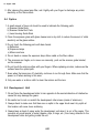
5.4 Optics . . . . . . . . . . . . . . . . . . . . . . . . . . . . . . . . . . . . . . . . . . . . . . . . . . . . . . . . . . . 4-20
5.5 Development Unit . . . . . . . . . . . . . . . . . . . . . . . . . . . . . . . . . . . . . . . . . . . . . . . . . . 4-20
5.6 Transfer and Separation Corona . . . . . . . . . . . . . . . . . . . . . . . . . . . . . . . . . . . . . . 4-21
5.7 Cleaning Unit . . . . . . . . . . . . . . . . . . . . . . . . . . . . . . . . . . . . . . . . . . . . . . . . . . . . . . 4-21
5.8 Pre-transfer and Quenching Unit . . . . . . . . . . . . . . . . . . . . . . . . . . . . . . . . . . . . . 4-21
5.9 Fusing . . . . . . . . . . . . . . . . . . . . . . . . . . . . . . . . . . . . . . . . . . . . . . . . . . . . . . . . . . . 4-21
5.10 Paper Feed and Duplex . . . . . . . . . . . . . . . . . . . . . . . . . . . . . . . . . . . . . . . . . . . . 4-21
5.11 Optional Equipment . . . . . . . . . . . . . . . . . . . . . . . . . . . . . . . . . . . . . . . . . . . . . . . 4-22
5.12 Handling PCBs . . . . . . . . . . . . . . . . . . . . . . . . . . . . . . . . . . . . . . . . . . . . . . . . . . . 4-22
REPLACEMENT AND ADJUSTMENT
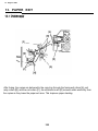
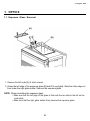
1. OPTICS . . . . . . . . . . . . . . . . . . . . . . . . . . . . . . . . . . . . . . . . . . . . . . 5-1
1.1 Exposure Glass Removal . . . . . . . . . . . . . . . . . . . . . . . . . . . . . . . . . . . . . . . . . . . . . 5-1
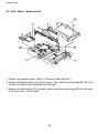
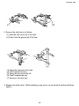
1.2 Sixth Mirror Replacement . . . . . . . . . . . . . . . . . . . . . . . . . . . . . . . . . . . . . . . . . . . . . 5-2
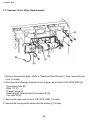
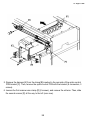
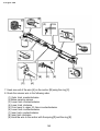
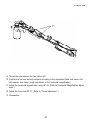
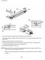
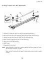
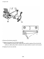
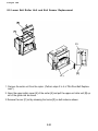
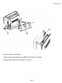
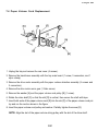
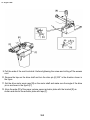
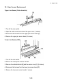
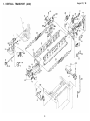
1.3 Scanner Drive Wire Replacement . . . . . . . . . . . . . . . . . . . . . . . . . . . . . . . . . . . . . . . 5-4
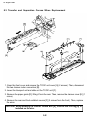
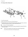
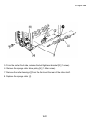
1.4 Fourth and fifth Mirror Drive Wire Replacement . . . . . . . . . . . . . . . . . . . . . . . . . . . 5-8
1.5 Lens Drive Wire Replacement . . . . . . . . . . . . . . . . . . . . . . . . . . . . . . . . . . . . . . . . . . 5-9
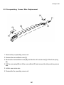
1.6 Scanner Harness Replacement (Optics Cables & Exposure Lamp) . . . . . . . . . . 5-10
2. DEVELOPMENT . . . . . . . . . . . . . . . . . . . . . . . . . . . . . . . . . . . . . . . 5-12
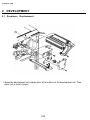
2.1 Developer Replacement . . . . . . . . . . . . . . . . . . . . . . . . . . . . . . . . . . . . . . . . . . . . . 5-12
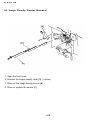
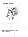
2.2 Image Density Sensor Removal . . . . . . . . . . . . . . . . . . . . . . . . . . . . . . . . . . . . . . . 5-14
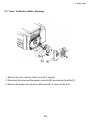
2.3 Toner Collection Bottle Cleaning . . . . . . . . . . . . . . . . . . . . . . . . . . . . . . . . . . . . . . 5-15
2.4 Vsg Voltage Checking . . . . . . . . . . . . . . . . . . . . . . . . . . . . . . . . . . . . . . . . . . . . . . . 5-16
2.5 Vsg Voltage Adjustment . . . . . . . . . . . . . . . . . . . . . . . . . . . . . . . . . . . . . . . . . . . . . 5-17
2.6 Toner Supply System Checking . . . . . . . . . . . . . . . . . . . . . . . . . . . . . . . . . . . . . . . 5-18
2.7 Toner Density Recovery . . . . . . . . . . . . . . . . . . . . . . . . . . . . . . . . . . . . . . . . . . . . . 5-19
2.8 Fixed Supply Mode Selection . . . . . . . . . . . . . . . . . . . . . . . . . . . . . . . . . . . . . . . . 5-19
2.9 Toner Amount Changing . . . . . . . . . . . . . . . . . . . . . . . . . . . . . . . . . . . . . . . . . . . . . 5-19
2.10 ID Pattern Bias Voltage Adjustment . . . . . . . . . . . . . . . . . . . . . . . . . . . . . . . . . . . 5-19
3. CLEANING . . . . . . . . . . . . . . . . . . . . . . . . . . . . . . . . . . . . . . . . . . . . 5-20
3.1 Pick-off Pawl Replacement . . . . . . . . . . . . . . . . . . . . . . . . . . . . . . . . . . . . . . . . . . . 5-20
3.2 Cleaning Blade and Brush Replacement . . . . . . . . . . . . . . . . . . . . . . . . . . . . . . . . 5-22
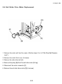
3.3 Blade Cleaner and Bias Roller Blade Replacement . . . . . . . . . . . . . . . . . . . . . . . . 5-23
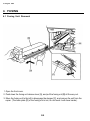
4. FUSING . . . . . . . . . . . . . . . . . . . . . . . . . . . . . . . . . . . . . . . . . . . . . . 5-24
4.1 Fusing Unit Removal . . . . . . . . . . . . . . . . . . . . . . . . . . . . . . . . . . . . . . . . . . . . . . . 5-24
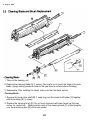
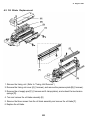
4.2 Oil Blade Replacement . . . . . . . . . . . . . . . . . . . . . . . . . . . . . . . . . . . . . . . . . . . . . . 5-25
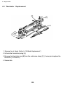
4.3 Thermistor Replacement . . . . . . . . . . . . . . . . . . . . . . . . . . . . . . . . . . . . . . . . . . . . . 5-26
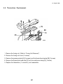
4.4 Thermofuse Replacement . . . . . . . . . . . . . . . . . . . . . . . . . . . . . . . . . . . . . . . . . . . . 5-27
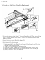
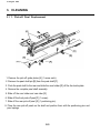
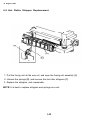
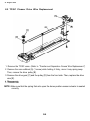
4.5 Hot Roller Stripper Replacement . . . . . . . . . . . . . . . . . . . . . . . . . . . . . . . . . . . . . . 5-28
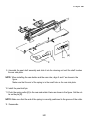
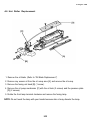
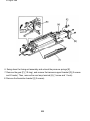
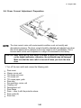
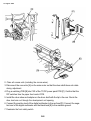
4.6 Hot Roller Replacement . . . . . . . . . . . . . . . . . . . . . . . . . . . . . . . . . . . . . . . . . . . . . 5-29
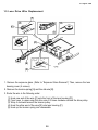
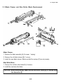
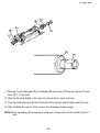
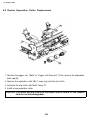
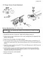
4.7 Pressure Roller Replacement . . . . . . . . . . . . . . . . . . . . . . . . . . . . . . . . . . . . . . . . . 5-32
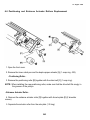
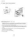
4.8 Entrance Guide Height Adjustment . . . . . . . . . . . . . . . . . . . . . . . . . . . . . . . . . . . . 5-33
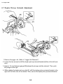
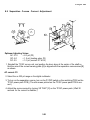
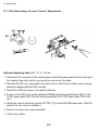
4.9 Fusing Pressure Adjustment . . . . . . . . . . . . . . . . . . . . . . . . . . . . . . . . . . . . . . . . . . 5-34
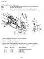
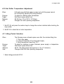
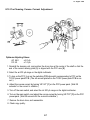
4.10 Hot Roller Temperature Adjustment . . . . . . . . . . . . . . . . . . . . . . . . . . . . . . . . . . . 5-35
4.11 Idling Period Selection . . . . . . . . . . . . . . . . . . . . . . . . . . . . . . . . . . . . . . . . . . . . . 5-35
5. PAPER FEED . . . . . . . . . . . . . . . . . . . . . . . . . . . . . . . . . . . . . . . . . 5-36
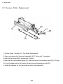
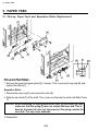
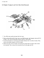
5.1 Pick-up, Paper Feed and Separation Roller Replacement . . . . . . . . . . . . . . . . . . 5-36
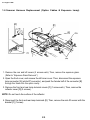
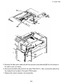
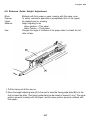
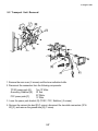
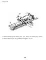
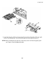
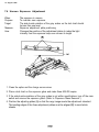
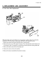
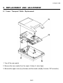
5.2 Transport Unit Removal . . . . . . . . . . . . . . . . . . . . . . . . . . . . . . . . . . . . . . . . . . . . . 5-37
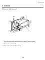
6. DUPLEX . . . . . . . . . . . . . . . . . . . . . . . . . . . . . . . . . . . . . . . . . . . . . . 5-39
6.2 Duplex Transport and Fork Gate Units Removal . . . . . . . . . . . . . . . . . . . . . . . . . . 5-40
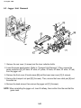
6.3 Jogger Unit Removal . . . . . . . . . . . . . . . . . . . . . . . . . . . . . . . . . . . . . . . . . . . . . . . 5-42
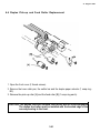
6.4 Duplex Pick-up and Feed Roller Replacement . . . . . . . . . . . . . . . . . . . . . . . . . . . 5-43
6.5 Duplex Separation Roller Replacement . . . . . . . . . . . . . . . . . . . . . . . . . . . . . . . . . 5-44
6.6 Positioning and Entrance Actuator Rollers Replacement . . . . . . . . . . . . . . . . . . . 5-45
6.7 Duplex Pick-up Solenoid Adjustment . . . . . . . . . . . . . . . . . . . . . . . . . . . . . . . . . . . 5-46
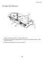
6.8 Jogger Wire Replacement . . . . . . . . . . . . . . . . . . . . . . . . . . . . . . . . . . . . . . . . . . . 5-47
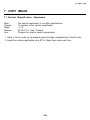
7. COPY IMAGE . . . . . . . . . . . . . . . . . . . . . . . . . . . . . . . . . . . . . . . . . 5-49
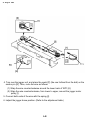
7.1 Vertical Magnification Adjustment . . . . . . . . . . . . . . . . . . . . . . . . . . . . . . . . . . . . . 5-49
7.2 Horizontal Magnification . . . . . . . . . . . . . . . . . . . . . . . . . . . . . . . . . . . . . . . . . . . . . 5-50
7.3 Focus Adjustment . . . . . . . . . . . . . . . . . . . . . . . . . . . . . . . . . . . . . . . . . . . . . . . . . . 5-51
7.4 Uneven Exposure Adjustment . . . . . . . . . . . . . . . . . . . . . . . . . . . . . . . . . . . . . . . . . 5-52
7.5 Light lntensity Adjustment . . . . . . . . . . . . . . . . . . . . . . . . . . . . . . . . . . . . . . . . . . . 5-53
7.6 ADS Reference Voltage Setting . . . . . . . . . . . . . . . . . . . . . . . . . . . . . . . . . . . . . . . 5-54
7.7 ADS Voltage Adjustment . . . . . . . . . . . . . . . . . . . . . . . . . . . . . . . . . . . . . . . . . . . . . 5-55
7.8 ADS Operation Checking . . . . . . . . . . . . . . . . . . . . . . . . . . . . . . . . . . . . . . . . . . . . 5-56
7.9 Erase Adjustment . . . . . . . . . . . . . . . . . . . . . . . . . . . . . . . . . . . . . . . . . . . . . . . . . . 5-56
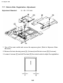
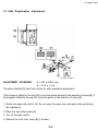
7.10 Registration Adjustment . . . . . . . . . . . . . . . . . . . . . . . . . . . . . . . . . . . . . . . . . . . . 5-57
7.11 Side-to-Side Registration Adjustment . . . . . . . . . . . . . . . . . . . . . . . . . . . . . . . . . 5-58
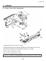
8. CORONA . . . . . . . . . . . . . . . . . . . . . . . . . . . . . . . . . . . . . . . . . . . . . 5-59
8.1 Charge Corona Wire Replacement . . . . . . . . . . . . . . . . . . . . . . . . . . . . . . . . . . . . 5-59
8.2 Pre-quenching Corona Wire Replacement . . . . . . . . . . . . . . . . . . . . . . . . . . . . . . 5-61
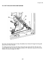
8.3 Transfer and Separation Corona Wires Replacement . . . . . . . . . . . . . . . . . . . . . . 5-62
8.4 Charge Cleaner Drive Wire Replacement . . . . . . . . . . . . . . . . . . . . . . . . . . . . . . . 5-63
8.5 TC/SC Cleaner Drive Wire Replacement . . . . . . . . . . . . . . . . . . . . . . . . . . . . . . . . 5-64
8.6 Drum Current Adjustment Preparation . . . . . . . . . . . . . . . . . . . . . . . . . . . . . . . . . . 5-65
8.7 Charge Corona Current Adjustment . . . . . . . . . . . . . . . . . . . . . . . . . . . . . . . . . . . 5-67
8.8 Transfer Corona Current Adjustment . . . . . . . . . . . . . . . . . . . . . . . . . . . . . . . . . . . 5-68
8.9 Separation Corona Current Adjustment . . . . . . . . . . . . . . . . . . . . . . . . . . . . . . . . 5-69
8.10 Pre-Cleaning Corona Current Adjustment . . . . . . . . . . . . . . . . . . . . . . . . . . . . . . 5-71
8.11 Pre-Quenching Corona Current Adjustment . . . . . . . . . . . . . . . . . . . . . . . . . . . . 5-72
9. OTHERS . . . . . . . . . . . . . . . . . . . . . . . . . . . . . . . . . . . . . . . . . . . . . 5-73
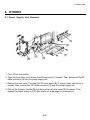
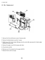
9.1 Power Supply Unit Removal . . . . . . . . . . . . . . . . . . . . . . . . . . . . . . . . . . . . . . . . . . 5-73
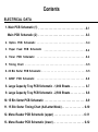
ELECTRICAL DATA
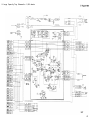
1. Main PCB Schematic (1) . . . . . . . . . . . . . . . . . . . . . . . . . . . . . . . . . 6-1
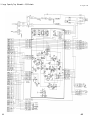
Main PCB Schematic (2) . . . . . . . . . . . . . . . . . . . . . . . . . . . . . . . . . 6-3
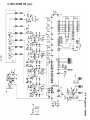
2. Optics PCB Schematic
. . . . . . . . . . . . . . . . . . . . . . . . . . . . . . .. . . 6-4
3. Paper Feed PCB Schematic . . . . . . . . . . . . . . . . . . . . . . . . . . . . . . 6-4
4. Timer PCB Schematic . . . . . . . . . . . . . . . . . . . . . . . . . . . . . . . . . . 6-4
5. Timing Chart . . . . . . . . . . . . . . . . . . . . . . . . . . . . . . . . . . . . . . . . . . 6-5
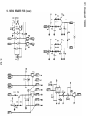
6. 20 Bin Sorter PCB Schematic . . . . . . . . . . . . . . . . . . . . . . . . . . . . 6-5
7. ARDF PCB Schematic . . . . . . . . . . . . . . . . . . . . . . . . . . . . . . . . . . 6-6
8. Large Capacity Tray PCB Schematic - 1,000 Sheets . . . . . . . . . . . 6-7
9. Large Capacity Tray PCB Schematic - 2,500 Sheets . . . . . . . . . . 6-8
10. 15 Bin Sorter PCB Schematic . . . . . . . . . . . . . . . . . . . . . . . . . . . 6-9
11. 15 Bin Sorter Timing Chart (A4/Letter Mode) . . . . . . . . . . . . . 6-10
12. Menu Reader PCB Schematic (upper) . . . . . . . . . . . . . . . . . . . . 6-11
13. Menu Reader PCB Schematic (lower) . . . . . . . . . . . . . . . . . . . . 6-12
PAPER BANK
1. SPECIFICATIONS . . . . . . . . . . . . . . . . . . . . . . . . . . . . . . . . . . . . . . . 7-1
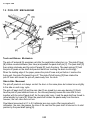
2. MECHANICAL COMPONENT LAYOUT . . . . . . . . . . . . . . . . . . . . . . 7-2
3. ELECTRICAL COMPONENT LAYOUT . . . . . . . . . . . . . . . . . . . . . . . 7-3
4. OVERVIEW . . . . . . . . . . . . . . . . . . . . . . . . . . . . . . . . . . . . . . . . . . . . 7-4
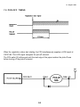
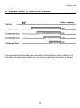
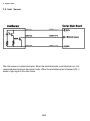
5. PAPER FEED CLUTCH ON TIMING . . . . . . . . . . . . . . . . . . . . . . . . . 7-5
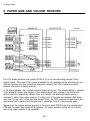
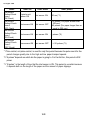
6. PAPER SlZE AND VOLUME SENSORS . . . . . . . . . . . . . . . . . . . . . . 7-6
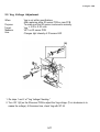
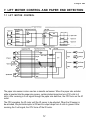
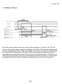
7. LIFT MOTOR CONTROL AND PAPER END DETECTION . . . . . . . 7-7
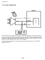
7.1 LIFT MOTOR CONTROL . . . . . . . . . . . . . . . . . . . . . . . . . . . . . . . . . . . . . . . . . . . . . . 7-7
7.2 PAPER END DETECTION . . . . . . . . . . . . . . . . . . . . . . . . . . . . . . . . . . . . . . . . . . . . . 7-8
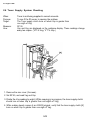
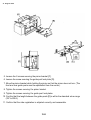
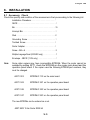
8. INSTALLATION . . . . . . . . . . . . . . . . . . . . . . . . . . . . . . . . . . . . . . . . . 7-9
8.1 Accessory Check . . . . . . . . . . . . . . . . . . . . . . . . . . . . . . . . . . . . . . . . . . . . . . . . . . . 7-9
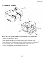
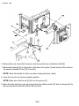
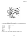
8.2 Installation Procedure . . . . . . . . . . . . . . . . . . . . . . . . . . . . . . . . . . . . . . . . . . . . . . . 7-10
DOCUMENT FEEDER
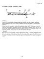
1. SPECIFICATIONS . . . . . . . . . . . . . . . . . . . . . . . . . . . . . . . . . . . . . . . 8-1
2. BASIC OPERATION . . . . . . . . . . . . . . . . . . . . . . . . . . . . . . . . . . . . . 8-2
2.1 INTERFACE . . . . . . . . . . . . . . . . . . . . . . . . . . . . . . . . . . . . . . . . . . . . . . . . . . . . . . . . 8-2
2.2 SINGLE-SIDED ORIGINAL FEED . . . . . . . . . . . . . . . . . . . . . . . . . . . . . . . . . . . . . . . 8-3
2.3 TWO-SIDED ORIGINAL FEED. . . . . . . . . . . . . . . . . . . . . . . . . . . . . . . . . . . . . . . . . 8-4
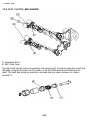
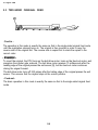
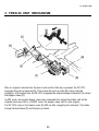
3. FEED-IN UNIT MECHANISM. . . . . . . . . . . . . . . . . . . . . . . . . . . . . . 8-5
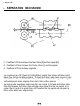
4. SEPARATION MECHANISM . . . . . . . . . . . . . . . . . . . . . . . . . . . . . . 8-6
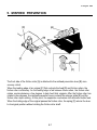
5. MISFEED PREVENTION . . . . . . . . . . . . . . . . . . . . . . . . . . . . . . . . . . 8-7
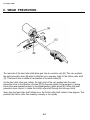
6. WEAR PREVENTION . . . . . . . . . . . . . . . . . . . . . . . . . . . . . . . . . . . . 8-8
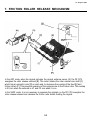
7. FRICTION ROLLER RELEASE MECHANISM . . . . . . . . . . . . . . . . . 8-9
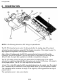
8. REGISTRATION . . . . . . . . . . . . . . . . . . . . . . . . . . . . . . . . . . . . . . . 8-10
9. INVERTER MECHANISM . . . . . . . . . . . . . . . . . . . . . . . . . . . . . . . . 8-11
10. FEED-OUT MECHANISM . . . . . . . . . . . . . . . . . . . . . . . . . . . . . . 8-12
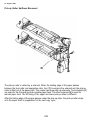
11. LIFT MECHANISM . . . . . . . . . . . . . . . . . . . . . . . . . . . . . . . . . . . . 8-13
12. MISFEED CHECK
. . . . . . . . . . . . . . . . . . . . . . . . . . . . . . . . . . . . 8-14
13. INSTALLATION . . . . . . . . . . . . . . . . . . . . . . . . . . . . . . . . . . . . . 8-16
13.1 Accessory Check . . . . . . . . . . . . . . . . . . . . . . . . . . . . . . . . . . . . . . . . . . . . . . . . . 8-16
13.2 Installation Procedure . . . . . . . . . . . . . . . . . . . . . . . . . . . . . . . . . . . . . . . . . . . . . . 8-17
14. REPLACEMENT AND ADJUSTMENT . . . . . . . . . . . . . . . . . . . . . 8-25
14.1 DF Belt Drive Motor Speed Adjustment . . . . . . . . . . . . . . . . . . . . . . . . . . . . . . . . 8-25
14.2 Inverter Turn Gate Solenoid Adjustment . . . . . . . . . . . . . . . . . . . . . . . . . . . . . . . 8-27
20 BIN SORTER
1. SPECIFICATIONS . . . . . . . . . . . . . . . . . . . . . . . . . . . . . . . . . . . . . . . 9-1
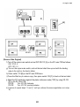
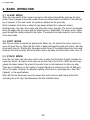
2. BASIC OPERATION . . . . . . . . . . . . . . . . . . . . . . . . . . . . . . . . . . . . . 9-2
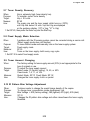
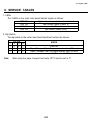
2.1 CLEAR MODE . . . . . . . . . . . . . . . . . . . . . . . . . . . . . . . . . . . . . . . . . . . . . . . . . . . . . . 9-2
2.2 SORT MODE . . . . . . . . . . . . . . . . . . . . . . . . . . . . . . . . . . . . . . . . . . . . . . . . . . . . . . . 9-2
2.3 STACK MODE . . . . . . . . . . . . . . . . . . . . . . . . . . . . . . . . . . . . . . . . . . . . . . . . . . . . . . 9-2
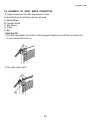
2.4 EXAMPLE OF SORT MODE OPERATION . . . . . . . . . . . . . . . . . . . . . . . . . . . . . . . . 9-3
3. BIN DRIVE MECHANISM . . . . . . . . . . . . . . . . . . . . . . . . . . . . . . . . . 9-6
4. BIN HOME POSITION . . . . . . . . . . . . . . . . . . . . . . . . . . . . . . . . . . . . 9-7
5. BINS . . . . . . . . . . . . . . . . . . . . . . . . . . . . . . . . . . . . . . . . . . . . . . . . . . 9-8
6. ELECTRICAL CONTROL . . . . . . . . . . . . . . . . . . . . . . . . . . . . . . . . . 9-9
7. INSTALLATION . . . . . . . . . . . . . . . . . . . . . . . . . . . . . . . . . . . . . . . . 9-10
7.1 Accessory Check . . . . . . . . . . . . . . . . . . . . . . . . . . . . . . . . . . . . . . . . . . . . . . . . . . 9-10
7.2 Installation Procedure . . . . . . . . . . . . . . . . . . . . . . . . . . . . . . . . . . . . . . . . . . . . . . . 9-11
8. REPLACEMENT AND ADJUSTMENT . . . . . . . . . . . . . . . . . . . . . . 9-15
8.1 Bin Drive Belt Replacement . . . . . . . . . . . . . . . . . . . . . . . . . . . . . . . . . . . . . . . . . . 9-15
8.2 Bin Drive Motor Replacement . . . . . . . . . . . . . . . . . . . . . . . . . . . . . . . . . . . . . . . . . 9-17
8.3 Bin Replacement . . . . . . . . . . . . . . . . . . . . . . . . . . . . . . . . . . . . . . . . . . . . . . . . . . . 9-18
8.4 Exit Roller Drive Motor Replacement . . . . . . . . . . . . . . . . . . . . . . . . . . . . . . . . . . . 9-19
8.5 Lower Exit Roller Unit and Exit Sensor Replacement . . . . . . . . . . . . . . . . . . . . . . 9-20
1 K LCT
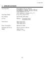
1. SPECIFICATIONS . . . . . . . . . . . . . . . . . . . . . . . . . . . . . . . . . . . . . . 10-1
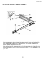
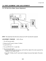
2. MECHANICAL COMPONENT LAYOUT . . . . . . . . . . . . . . . . . . . . . 10-2
3. DRIVE LAYOUT AND DRIVE MECHANISM . . . . . . . . . . . . . . . . . . 10-3
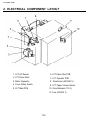
4. ELECTRICAL COMPONENT LAYOUT . . . . . . . . . . . . . . . . . . . . . . 10-4
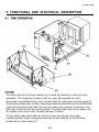
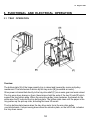
5. FUNCTIONAL AND ELECTRICAL DESCRIPTlON . . . . . . . . . . . . 10-5
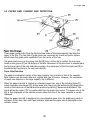
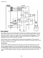
5.1 TRAY OPERATION . . . . . . . . . . . . . . . . . . . . . . . . . . . . . . . . . . . . . . . . . . . . . . . . . 10-5
5.2 PAPER SIZE CHANGE AND DETECTION . . . . . . . . . . . . . . . . . . . . . . . . . . . . . . 10-7
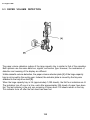
5.3 PAPER VOLUME DETECTION . . . . . . . . . . . . . . . . . . . . . . . . . . . . . . . . . . . . . . . 10-8
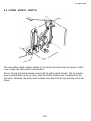
5.4 COVER SAFETY SWITCH . . . . . . . . . . . . . . . . . . . . . . . . . . . . . . . . . . . . . . . . . . . 10-9
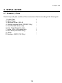
6. INSTALLATION . . . . . . . . . . . . . . . . . . . . . . . . . . . . . . . . . . . . . . . 10-10
6.1 Accessory Check . . . . . . . . . . . . . . . . . . . . . . . . . . . . . . . . . . . . . . . . . . . . . . . . . 10-10
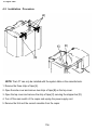
6.2 Installation Procedure . . . . . . . . . . . . . . . . . . . . . . . . . . . . . . . . . . . . . . . . . . . . . . 10-11
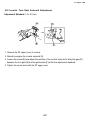
7. REPLACEMENT AND ADJUSTMENT . . . . . . . . . . . . . . . . . . . . . 10-15
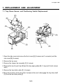
7.1 Tray Down Sensor and Positioning Switch Replacement . . . . . . . . . . . . . . . . . . 10-15
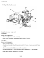
7.2 Paper Size Sensor Replacement . . . . . . . . . . . . . . . . . . . . . . . . . . . . . . . . . . . . 10-17
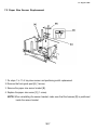
7.3 Tray Wire Replacement . . . . . . . . . . . . . . . . . . . . . . . . . . . . . . . . . . . . . . . . . . . . . 10-18
7.4 Paper Volume Cord Replacement . . . . . . . . . . . . . . . . . . . . . . . . . . . . . . . . . . . . . 10-21
7.5 Side Registration Adjustment . . . . . . . . . . . . . . . . . . . . . . . . . . . . . . . . . . . . . . . . 10-23
2.5 K LCT
1. SPECIFICATIONS . . . . . . . . . . . . . . . . . . . . . . . . . . . . . . . . . . . . . . 11-1
2. ELECTRICAL COMPONENT LAYOUT . . . . . . . . . . . . . . . . . . . . . . 11-2
3. FUNCTIONAL AND ELECTRICAL OPERATION . . . . . . . . . . . . . . 11-3
3.1 TRAY OPERATION . . . . . . . . . . . . . . . . . . . . . . . . . . . . . . . . . . . . . . . . . . . . . . . . . 11-3
4. INSTALLATION . . . . . . . . . . . . . . . . . . . . . . . . . . . . . . . . . . . . . . . . 11-5
4.1 Accessory Check . . . . . . . . . . . . . . . . . . . . . . . . . . . . . . . . . . . . . . . . . . . . . . . . . . 11-5
4.2 Installation Procedure . . . . . . . . . . . . . . . . . . . . . . . . . . . . . . . . . . . . . . . . . . . . . . . 11-6
MENU READER
1. SPECIFICATIONS . . . . . . . . . . . . . . . . . . . . . . . . . . . . . . . . . . . . . . 12-1
2. OVERALL MACHINE CONTROL . . . . . . . . . . . . . . . . . . . . . . . . . . 12-2
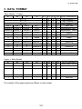
3. DATA FORMAT . . . . . . . . . . . . . . . . . . . . . . . . . . . . . . . . . . . . . . . . 12-3
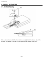
4. BASIC OPERATION . . . . . . . . . . . . . . . . . . . . . . . . . . . . . . . . . . . . 12-4
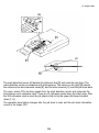
4.1 Job Sheet Reading . . . . . . . . . . . . . . . . . . . . . . . . . . . . . . . . . . . . . . . . . . . . . . . . . 12-4
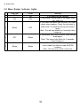
4.2 Menu Reader Indicator Lights . . . . . . . . . . . . . . . . . . . . . . . . . . . . . . . . . . . . . . . . 12-6
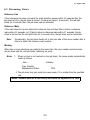
4.3 Processing Errors . . . . . . . . . . . . . . . . . . . . . . . . . . . . . . . . . . . . . . . . . . . . . . . . . . 12-7
5. INSTALLATION . . . . . . . . . . . . . . . . . . . . . . . . . . . . . . . . . . . . . . . . 12-8
5.1 ACCESSORY CHECK . . . . . . . . . . . . . . . . . . . . . . . . . . . . . . . . . . . . . . . . . . . . . . . 12-8
5.2 INSTALLATION PROCEDURE . . . . . . . . . . . . . . . . . . . . . . . . . . . . . . . . . . . . . . . . 12-9
6. REPLACEMENT AND ADJUSTMENT . . . . . . . . . . . . . . . . . . . . . 12-11
6.1 Lower Transport Roller Replacement . . . . . . . . . . . . . . . . . . . . . . . . . . . . . . . . . . 12-11
TROUBLESHOOTING
1. SERVICE CALL CONDITIONS . . . . . . . . . . . . . . . . . . . . . . . . . . . . 13-1
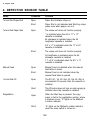
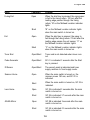
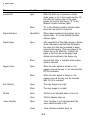
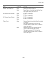
2. DEFECTIVE SENSOR TABLE . . . . . . . . . . . . . . . . . . . . . . . . . . . . . 13-8
15 BIN SORTER
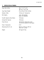
1. SPECIFICATIONS . . . . . . . . . . . . . . . . . . . . . . . . . . . . . . . . . . . . . . 14-1
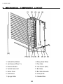
2. MECHANICAL COMPONENT LAYOUT . . . . . . . . . . . . . . . . . . . . . 14-2
3. DRIVE LAYOUT . . . . . . . . . . . . . . . . . . . . . . . . . . . . . . . . . . . . . . . 14-3
4. ELECTRICAL COMPONENT LAYOUT . . . . . . . . . . . . . . . . . . . . . . 14-4
5. ELECTRICAL COMPONENT DESCRIPTIONS . . . . . . . . . . . . . . . 14-5
6. BASIC OPERATION . . . . . . . . . . . . . . . . . . . . . . . . . . . . . . . . . . . . 14-6
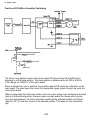
7. FUNCTIONAL AND ELECTRICAL DESCRIPTION . . . . . . . . . . . 14-10
7.1 Power Supply . . . . . . . . . . . . . . . . . . . . . . . . . . . . . . . . . . . . . . . . . . . . . . . . . . . . 14-10
7.2 Bin Gate Operation . . . . . . . . . . . . . . . . . . . . . . . . . . . . . . . . . . . . . . . . . . . . . . . . 14-11
7.3 Relay Guide Plate Reset Mechanism . . . . . . . . . . . . . . . . . . . . . . . . . . . . . . . . . 14-12
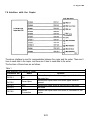
7.4 Interface with the Copier . . . . . . . . . . . . . . . . . . . . . . . . . . . . . . . . . . . . . . . . . . . . 14-13
7.5 Jam Sensors . . . . . . . . . . . . . . . . . . . . . . . . . . . . . . . . . . . . . . . . . . . . . . . . . . . . . 14-15
7.6 Inlet Sensor . . . . . . . . . . . . . . . . . . . . . . . . . . . . . . . . . . . . . . . . . . . . . . . . . . . . . . 14-16
7.7 Misfeed Check . . . . . . . . . . . . . . . . . . . . . . . . . . . . . . . . . . . . . . . . . . . . . . . . . . . . 14-17
8. INSTALLATION . . . . . . . . . . . . . . . . . . . . . . . . . . . . . . . . . . . . . . . 14-19
8.1 Accessory Check . . . . . . . . . . . . . . . . . . . . . . . . . . . . . . . . . . . . . . . . . . . . . . . . . 14-19
8.2 Installation Procedure . . . . . . . . . . . . . . . . . . . . . . . . . . . . . . . . . . . . . . . . . . . . . . 14-20
9. SERVICE TABLES . . . . . . . . . . . . . . . . . . . . . . . . . . . . . . . . . . . . . 14-25
10. REPLACEMENT AND ADJUSTMENT . . . . . . . . . . . . . . . . . . . . 14-27
10.1 Sorter Removal . . . . . . . . . . . . . . . . . . . . . . . . . . . . . . . . . . . . . . . . . . . . . . . . . . 14-27
10.2 Inlet sensor Replacement . . . . . . . . . . . . . . . . . . . . . . . . . . . . . . . . . . . . . . . . . . 14-28
10.3 Jam Sensor Replacement . . . . . . . . . . . . . . . . . . . . . . . . . . . . . . . . . . . . . . . . . . 14-29
10.4 Sponge Roller Replacement . . . . . . . . . . . . . . . . . . . . . . . . . . . . . . . . . . . . . . . . 14-30
10.5 DC Motor Replacement . . . . . . . . . . . . . . . . . . . . . . . . . . . . . . . . . . . . . . . . . . . 14-32
SECTION 1
OVERALL MACHINE
INFORMATION
1. SPECIFICATIONS . . . . . . . . . . . . . . . . . . . . . . . . . . . . . . . . . . . . . . 1-1
2. GUIDE TO COMPONENTS . . . . . . . . . . . . . . . . . . . . . . . . . . . . . . . . 1-4
2.1 INTERNAL/EXTERNAL . . . . . . . . . . . . . . . . . . . . . . . . . . . . . . . . . . . . . . . . . . . . . . 1-4
2.2 OPERATION PANEL . . . . . . . . . . . . . . . . . . . . . . . . . . . . . . . . . . . . . . . . . . . . . . . . . 1-6
2.3 INDICATOR SCREEN . . . . . . . . . . . . . . . . . . . . . . . . . . . . . . . . . . . . . . . . . . . . . . . . 1-8
2.4 GUIDANCE DISPLAY . . . . . . . . . . . . . . . . . . . . . . . . . . . . . . . . . . . . . . . . . . . . . . . . 1-9
3. COPY PROCESSES AROUND THE DRUM . . . . . . . . . . . . . . . . . . 1-10
4. COPY CYCLE . . . . . . . . . . . . . . . . . . . . . . . . . . . . . . . . . . . . . . . . 1-12
5. PAPER PATH . . . . . . . . . . . . . . . . . . . . . . . . . . . . . . . . . . . . . . . . . 1-13
6. DRIVE LAYOUT
. . . . . . . . . . . . . . . . . . . . . . . . . . . . . . . . . . . . . . . 1-16
7. MECHANICAL COMPONENT LAYOUT . . . . . . . . . . . . . . . . . . . . . 1-17
8. ELECTRICAL COMPONENT LAYOUT . . . . . . . . . . . . . . . . . . . . . 1-18
9. ELECTRICAL COMPONENT DESCRIPTIONS . . . . . . . . . . . . . . . 1-23
10. OVERALL MACHINE CONTROL . . . . . . . . . . . . . . . . . . . . . . . . . 1-28
11. AC AND DC POWER DISTRIBUTION . . . . . . . . . . . . . . . . . . . . . 1-29
31 August 1989
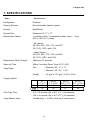
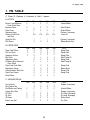
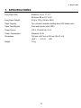
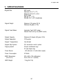
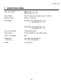
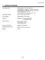
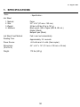
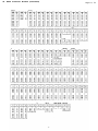
1. SPECIFICATIONS
- Item -
- Specifications -
Configuration:
Desk top
Copying Process:
Dry electrostatic transfer system
Original:
Book/Sheet
Original Size:
Maximum A3, 11” x 17”
Reproduction Ratios:
5 reduction ratios, 3 enlargement ratios, zoom : – from
60% to 155% in 1% steps
- A4 Version 5R: 93%, 82%, 75%, 71%, and 65%
3E: 115%, 122%, and 141%
- Letter Version 5R: 93%, 85%, 77%, 74%, and 65%
3E: 121%, 129%, and 155%
Reproduction Ratio Change:
Maximum 6.5 seconds
Warm-Up Time:
Within 5 minutes (Room Temp. 20°C, 68°F)
Copy Paper
Size:
– Maximum A3, 11” x 17”
– Minimum A6, 5½” x 8½”
Weight:
– 52 g/m2 to 157 g/m2 (14 lb to 42 lb)
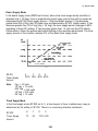
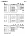
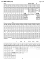
Copying Speed:
F33
A3
(11” x 17”)
22
18
A4 (S)
(11” x 8½”)
43
35
A4 (L)
(8½” x 11”)
33
27
A5 (S)
5½” x 8½”)
48
38
First Copy Time:
F33: 3.8 seconds (A4 or 8½” x 11”) (1st cassette)
F34: 4.2 seconds (A4 or 8½” x 11”) (1st cassette)
Copy Number Input:
Number keys, 1 to 999 (count up or count down)
1-1
31 August 1989
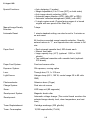
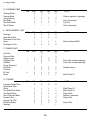
Special Functions:
•
•
•
•
•
•
Auto duplexing (3 modes)
Margin adjustment (0 to 16 mm [5/8”] on both sides)
Auto image density selection (ADS)
Automatic paper selection (APS) (with ADF or RDH)
Automatic reduction/enlargement (AMS) (with ADF)
2 single copies mode (Copies facing pages of a bound
original with one press of the Start key.)
Manual Image Density
Selection:
7 steps
Automatic Reset:
1 minute standard setting; can also be set to 3 minutes or
no auto reset.
All functions canceled except cassette selection. Quantity
entered returns to “1”, and reproduction ratio returns to full
size.
Paper Feed:
• Dual universal cassette feed, 500 sheets each
• Manual feed table
• Large capacity tray (LCT) (optional: 1,000 or 2,500
sheets)
• Two additional cassettes with cassette bank (optional:
500 sheets)
Paper Feed System:
Feed and reverse roller
Exposure System:
Slit exposure, moving optics
Lens:
Through lens, F5, f = 215 mm
Light Source:
Halogen lamp (85 V, 160 W; control range 50 to 80 volts
RMS)
Photoconductor:
Selenium drum (F-type)
Charge System:
Dual wire dc corona
Erase:
LED lamp unit (80 segments)
Development System:
Magnetic brush roller
Development:
Automatic voltage change (The control board monitors the
selected image density level, drum temperature, and rest
time.)
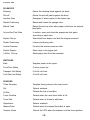
Toner Replenishment:
Cartridge exchange (330 g/bottle)
Toner Consumption:
10,000 copies/bottle (7%/A4)
1-2
31 August 1989
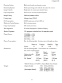
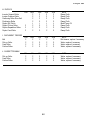
Cleaning System:
Blade and brush, pre-cleaning corona
Quenching System:
Photo-quenching (cold cathode tube) and dc corona
Image Transfer:
Single wire dc corona, pre-transfer lamp
Paper Separation:
Dual wire ac corona and pick-off pawls
Image Fusing:
Heat and pressure rollers
Fusing Lamp:
Halogen lamp (750 W)
Oil Consumption:
80,000 copies per oil tank (360 cc)
Electronic Control System:
8-bit microprocessor
Copy Tray Capacity:
250 sheets (all sizes)
Self-diagnostics:
24 codes, displayed in Guidance Display
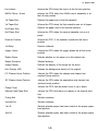
Service Programs:
100 programs controlled from the operation panel
Power Source:
110V/60Hz –> 15A
115V/60Hz –> 15A
220V/50Hz –> 8A
240V/50Hz –> 8A
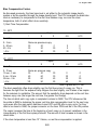
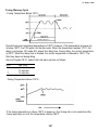
Power Consumption:
See the following table. Numbers are in kilowatts per hour.
Warm-up
1.0
Copier
Dimensions:
Copying
1.8
Stand-by
0.18
Max.
1.5
See the following table. The numbers are in millimeters
with inches in parenthesis:
Height
Depth
Width
763 mm
750 mm
500 mm
Copier only with
(19.7”)
platen cover
(29.5”)
(30.0”)
Full System*
1,575 mm
(62.0”)
763 mm
(30.0”)
1,065 mm
(41 .9”)
*With DF, Sorter, LCT (RT21), Paper Bank, Menu Reader
Weight:
(Duplex Model):
(Non-duplex Model):
1-3
115V - 104 kg (228.5 lb)
220V - 107 kg (235.4 lb)
115V - 96 kg (211.2 Ib)
220V - 99 kg (217.8 lb)
31 August 1989
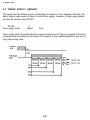
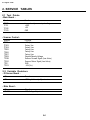
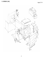
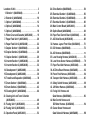
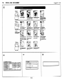
2. GUIDE TO COMPONENTS
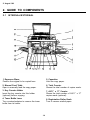
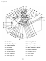
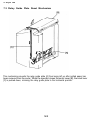
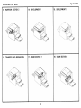
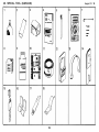
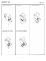
2.1 lNTERNAL/EXTERNAL
1. Exposure Glass
Position the original to be copied here.
5. Cassettes
Hold the copy paper.
2. Manual Feed Table
Open to manually feed the copy paper.
6. Total Counter
Shows the total number of copies made.
3. Key Counter Holder
Insert the key counter into this holder
[optional] before copying.
7. A3/11” x 17” Counter
Shows the total number of A3/11” x 17”
copies made (optional).
4. Toner Bottle Lever
Turn counterclockwise to remove the toner
bottle from its holder.
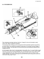
8. Registration Roller Knob
Turn to remove misfed paper.
1-4
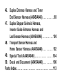
31 August 1989
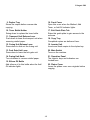
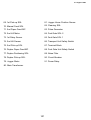
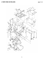
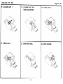
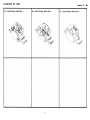
9. Duplex Tray
Stores the copies before reverse side
copying.
16. Front Cover
Open this cover when the Misfeed, Add
Toner, or Add Oil indicator lights.
10. Toner Bottle Holder
Swing down to replace the toner bottle.
17. Exit Guide Plate Tab
Raise this guide plate to gain access to the
exit area.
11. Transport Unit Release Lever
Push down to lower the transport unit when
removing misfed paper.
18. Copy Tray
Completed copies are delivered here.
12. Fusing Unit Release Lever
Press down to slide out the fusing unit.
19. Inverter Unit
Inverts and feeds copies to the duplex tray.
13. Fork Gate Unit Lever
Press down to lower the fork gate unit.
20. Main Switch
Turns on the machine.
14. Fusing Unit Knob
Turn clockwise to remove misfed paper.
21. Operation Panel
The copier’s keys and indicators are
located here.
15. Silicon Oil Bottle
Add silicone oil to this bottle when the Add
Oil indicator lights.
22. Platen Cover
Lower the platen cover over originals before
copying.
1-5
31 August 1989
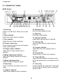
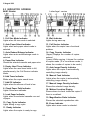
2.2 OPERATION PANEL
A4/A3 Version
10. Guidance Key
Press to select guidance mode.
1. Sorter Key
Press to use the sorter. Select sort or stack
mode.
11. Enter Key
Press after entering data.
2. Stack Indicator
Lights when stack mode is selected.
12. Interrupt Indicator
Lights when interrupt mode is selected.
3. Sort Indicator
Lights when sort mode is selected.
13. Interrupt Key
Press to make interrupt copies during a
copy run.
4.2 Single Copies Key
Press to make copies from bound originals
or two sided originals.
14. Program Indicator
Lights when the user program mode is
selected.
5.2 Single Copies Indicator
Lights when 2 single copies mode is
selected.
15. Program Key
Press to enter or recall user programs.
6. Margin Adjustment Indicator
Lights when Margin Adjustment mode is
selected.
16. Timer Indicator
Lights when the machine has been turned
off by the weekly timer or automatic shut-off
timer.
7. Margin Adjustment Key
Press to create a margin on copies.
17. Timer Key
Press to operate the copier after it has been
turned off by the weekly timer or automatic
shut-off timer.
8. Zoom Keys
Press to alter the reproduction ratio in 1%
steps.
9. Guidance Indicator
Lights when guidance mode is selected.
1-6
31 August 1989
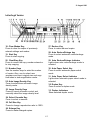
Letter/Legal Version
27. Reduce Key
Press to make reduced copies.
18. Clear Modes Key
Press to clear the copier of previously
entered settings and modes.
19. Start Key
Press to start copying.
28. Auto Reduce/Enlarge key
Press to select automatic reduce/enlarge
mode.
20. Clear/Stop Key
Press to cancel the copy number entered or
to stop copying.
29. Auto Reduce/Enlarge Indicator
Lights when auto reduce/enlarge mode is
selected.
21. Number Keys
Use the number keys to enter the number
of copies. Also, use to select user
programs and input original size and copy
size when in size magnification mode.
30. Auto Paper Select Key
Press to select automatic paper select
mode.
31. Auto Paper Select Indicator
Lights when automatic paper select mode is
selected.
22. Auto Image Density Key
Press to select/clear automatic image
density mode.
32. Duplex Key
Press to select a duplex mode.
23. Image Density Keys
Press to cancel automatic control and
manually select the image density level.
33. Duplex Indicators
Show selected duplex mode.
24. Select Cassette Key
Press to select a cassette.
25. Full Size Key
Press to change reproduction ratio to 100%.
26. Enlarge Key
Press to make enlarged copies.
1-7
31 August 1989
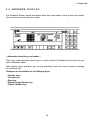
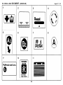
2.3 INDICATOR SCREEN
A4/A3 Version
Letter/legal version
1. Full Size Mode Indicator
Lights when full size mode is selected.
12. Wait Indicator
Lights during warm-up.
2. Auto Paper Select Indicator
Lights when auto paper select mode is
selected.
13. Call Service Indicator
Lights when the copier has a functional
problem.
3. Auto Reduce/Enlarge Indicator
Lights when auto reduce/enlarge mode is
selected.
14. Copy Counter Indicator
(Upper) Displays the number of copies
entered.
(Lower) While copying, it shows the number
of copies made. (If in count-down mode, it
shows the number of copies to be made.)
4. Paper Size Indicator
Shows the selected cassette and paper size.
5. Empty Used Toner Indicator
Lights when the used toner bottle is full;
simultaneously, the Call Service indicator
blinks.
15. Auto Image Density Indicator
Lights when the copier is automatically
controlling image density.
6. Add Toner Indicator
Blinks when the copier needs toner.
16. Manual Feed Indicator
Lights when the copier is automatically
controlling image density.
7. Add Oil Indicator
Lights when the silicone oil level is low.
17. Manual Image Density Indicator
Shows the selected image density.
8. Check Paper Path Indicator
Lights if there are misfeeds.
18. Misfeed Location Display
Shows where to check inside the copier if
there is a misfeed.
9. Load Paper Indicator
Lights when the selected cassette runs out
of paper.
19. Magnification Ratio Indicator
Shows the selected reproduction ratio.
10. Copy Cycle Indicator
Lights during a copy cycle.
20. Zoom Indicator
Lights when zoom mode is selected.
11. Ready Indicator
Lights when the copier is ready to copy.
1-8
31 August 1989
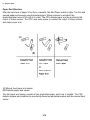
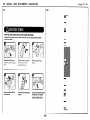
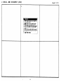
2.4 GUIDANCE D I S P L A Y
The Guidance Display shows information about keys and modes, and it guides you through
the procedures for operating the copier.
- Information about keys and modes When you need information about keys or modes, press the Guidance key and the key you
want information about.
After starting copier operation, you can get information about the current mode by pressing
the Guidance key.
Guidance is not available for the following Keys:
•
•
•
•
•
Number keys
Decimal key
Start key
Manual Image Density key
Select Cassette key
1-9
31 August 1989
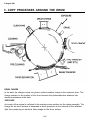
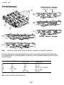
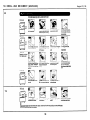
3. COPY PROCESSES AROUND THE DRUM
DRUM CHARGE
In the dark, the charge corona unit gives a uniform positive charge to the selenium drum. The
charge remains on the surface of the drum because the photoconductive selenium has
electrical resistance in the dark.
EXPOSURE
An image of the original is reflected to the selenium drum surface via the optics assembly. The
charge on the drum surface is dissipated in direct proportion to the intensity of the reflected
light, thus producing an electrical latent image on the drum surface.
1-10
31 August 1989
ERASE
The erase lamp illuminates the areas of the charged drum surface that will not be used for the
copy image. The resistance of the drum in the illuminated areas drops and the charge on
those areas dissipates.
DEVELOPMENT
Negatively charged toner is attracted to the positively charged areas of the drum, thus
developing the latent image. (The negative triboelectric charge is caused by friction between
the carrier and toner particles.)
PRE-TRANSFER LAMP (PTL)
The PTL illuminates the drum to remove all positive charge from the exposed areas of the
drum. This prevents the toner particles from being reattracted to the drum surface during
paper separation and makes paper separation easier.
IMAGE TRANSFER
Paper is fed to the drum surface at the proper time so as to align the copy paper and the
developed image on the drum surface. Then, a strong positive charge is applied to the back
side of the copy paper, providing an electrical force which pulls the toner particles from the
drum surface to the copy paper. At the same time, the copy paper is electrically attracted to
the drum surface.
PAPER SEPARATION
A strong ac corona discharge is applied to the back side of the copy paper, reducing the
positive charge on the copy paper and breaking the electrical attraction between the paper
and the drum. Then, the stiffness of the copy paper causes it to separate from the drum
surface. The pick-off pawls help to separate paper which has low stiffness.
PRE-CLEANING
The pre-cleaning corona (PCC) applies an ac corona with a negative bias to the drum. This
removes the positive charge from the drum and makes the negative charge on the toner
remaining on the drum even.
CLEANING
The cleaning brush removes most of the toner on the drum and loosens the remainder. Then,
the bias roller, which has a positive potential, attracts the toner particles from the cleaning
brush to keep it clean. Finally, the cleaning blade scrapes off the loosened toner.
QUENCHING
The pre-quenching corona applies a positive corona charge to the selenium drum to eliminate
any negative charge remaining from the pre-cleaning corona. Then, light from the quenching
lamp electrically neutralizes the drum.
1-11
31 August 1989
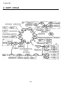
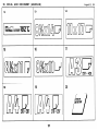
4. COPY CYCLE
1-12
31 August 1989
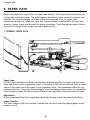
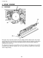
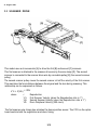
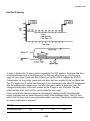
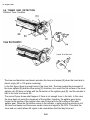
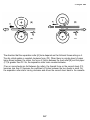
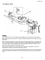
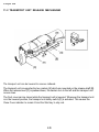
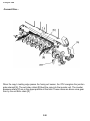
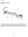
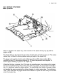
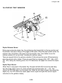
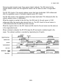
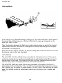
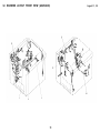
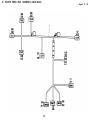
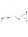
5. PAPER PATH
Paper feed starts from one of the four paper feed stations. The copy paper then follows one
of two paths inside the copier. The path followed depends on which mode the operator has
selected. For copy processing, all sheets follow the same path from the paper feed
mechanism through the fusing unit. After that, normal copies are delivered to the copy tray;
however, duplex copies are diverted for further processing. The following discussion follows
the route of a single sheet of paper through a duplex cycle.
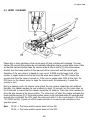
1. PRIMARY PAPER PATH
Paper Feed:
An FRR (Feed and Reverse Roller) mechanism separates one sheet of paper from the paper
stack and feeds it to the registration rollers. If the paper is fed from the second, third, or fourth
station, relay rollers move the paper to the registration roller. The registration rollers are not
turning at this time. The paper buckles slightly when the leading edge reaches the registration
rollers. Buckling seats the sheet securely between the registration rollers and corrects skew.
Registration:
At the programmed time, the registration rollers start turning to feed the paper to the drum.
Image Transfer:
The toner image on the drum surface is pulled from the drum onto the passing paper by the
transfer corona.
1-13
31 August 1989
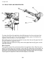
Paper Separation:
The electrostatic attraction between the paper and the drum is broken by the separating
corona. The suction of the vacuum fan and the weight of the paper pulls the paper onto the
transport belt. The transport belt moves the paper with the developed copy image to the
fusing unit.
Fusing:
The paper passes between two rollers which bond the toner image to the paper by applying
heat and pressure. At this point the copy is complete, and the paper path splits two ways.
Ordinary copies go directly through the exit rollers to the copy tray. Duplex copies are
diverted to the inverter unit.
1-14
31 August 1989
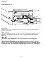
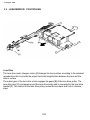
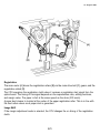
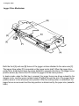
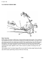
2. DUPLEX COPY PATH
Inverter Unit:
The junction gate directs the paper to the inverter unit, which inverts the copy and sends it to
the duplex transport unit.
Duplex Transport:
The duplex transport rollers move the copy to the right. The appropriate fork gate is opened
according to the paper size. Then, the copy is sent to the jogger unit through the duplex
delivery tray.
Jogger Unit:
The copies are neatly stacked in the jogger unit to prepare them for duplex paper feed.
Duplex Paper Feed
The copy is kept in the duplex tray until the operator sets the next original and presses the
Start key. Then the duplex feed mechanism feeds the copy up through the first relay rollers to
the registration rollers. After reaching the registration rollers, the sheet follows the same path
as when the front side was copied. However, this time the reverse side faces up to receive the
image.
1-15
31 August 1989
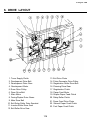
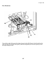
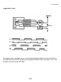
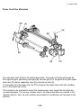
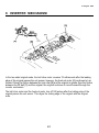
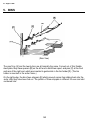
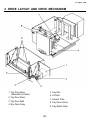
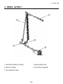
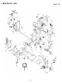
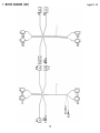
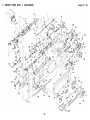
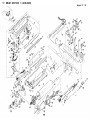
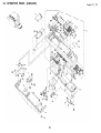
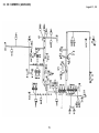
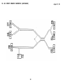
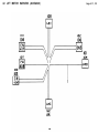
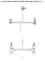
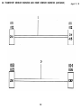
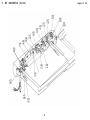
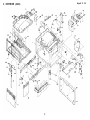
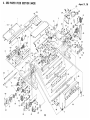
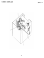
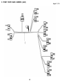
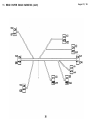
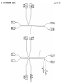
6. DRIVE LAYOUT
1. Toner Supply Clutch
2. Development Drive Belt
3. Development Drive Gear
4. Development Motor
13. Exit Drive Chain
14. Pulse Generator Drive Pulley
15. Registration Roller Drive Belt
16. Cleaning Drive Gear
5. Drum Drive Pulley
6. Drum Drive Belt
7. Main Motor
8. Fusing/Duplex Drive Gears
17. Registration Clutch
18. Paper Feed Motor
19. Duplex Paper Feed Clutch
20. Relay Roller Clutch
9. Main Drive Belt
10. Exit Relay Roller Drive Sprocket
11. Inverter Roller Drive Gear
12. Exit Roller Drive Gear
21. Paper Feed Drive Chain
22. Second Paper Feed Clutch
23. First Paper Feed Clutch
1-16
31 August 1989
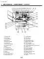
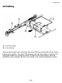
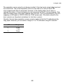
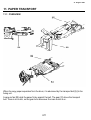
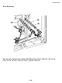
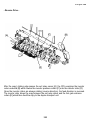
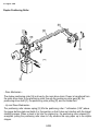
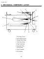
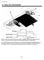
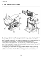
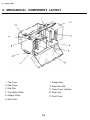
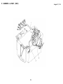
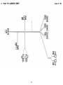
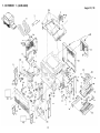
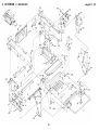
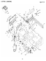
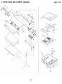
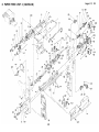
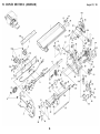
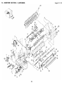
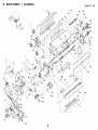
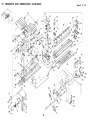
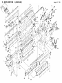
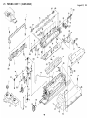
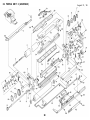
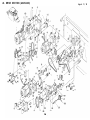
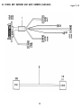
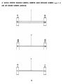
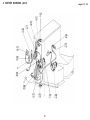
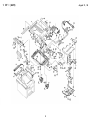
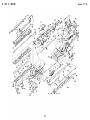
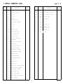
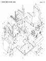
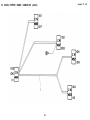
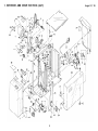
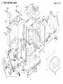
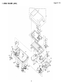
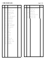
7. MECHANICAL COMPONENT LAYOUT
1. Inverter Unit
2. Third Mirror
3. Second Mirror
4. First Mirror
5. Exposure Lamp
6. Fusing Unit
7. Document Feeder
8. Transport Unit
9. Lens
10. Cleaning Unit
11. Quenching Unit
12. Charge Corona Unit
13. Drum
14. Sixth Mirror
15. Toner Shield Glass
16. Erase Lamp Unit
17. Fourth Mirror
18. Fifth Mirror
19. Toner Tank
20. Development Unit
21. Manual Feed Table
22. First Cassette
23. Large Capacity Tray
24. Transfer/Separation Corona Unit
25. Jogger Unit
26. Fourth Cassette
27. Cassette Bank
28. Third Cassette
29. Duplex Delivery Tray
30. Fork Gate Unit
31. Duplex Transport Unit
32. Sorter
31 August 1989
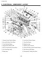
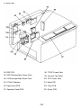
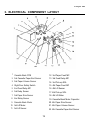
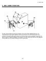
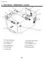
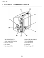
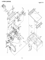
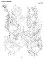
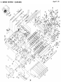
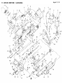
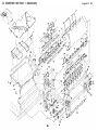
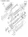
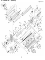
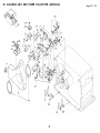
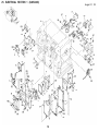
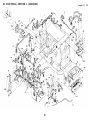
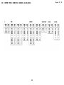
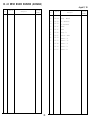
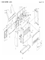
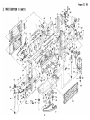
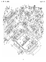
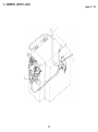
8. ELECTRICAL COMPONENT LAYOUT
1. Scanner Home Position Sensor
8. Lens Home Position Sensor
2. 4th and 5th Mirror Drive Motor
9. Toner End Sensor
3. Toner Overflow Sensor
10. Exposure Lamp
4. Image Density Sensor PCB
11. Scanner Overrun Sensor
5. PQC (Pre-quenching Corona Wire)
12. 4th and 5th Mirror Home Position Sensor
6. QL (Quenching Lamp)
13. Auto Density (AD) Sensor
7. Erase Lamp
14. Development Cooling Fan Motor
1-18
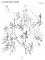
31 August 1989
15. Cooling Blower Motor
34. Drum Heater
16. Platen Cover Sensor
35. Duplex Entrance Sensor
17. CC Cleaner Home Position Sensor
36. Front Door Safety Switch
18. Key Counter (Option)
37. Fusing Lamp
19. Manual Feed Sensor
38. Oil End Sensor
20. CC Cleaner Motor
39. Fusing Thermistor
21. 1st Cassette Paper End Sensor
40. Main Switch
22. Manual Feed Paper End Sensor
41. AC Drive PCB
23. 1st Paper Size Sensor
42. Power Supply Unit
24. Registration Sensor
43. Exit Sensor
25. Pre-Transfer Lamp (PTL)
44. Exit Relay Sensor
26. 2nd Cassette Paper End Sensor
45. Inverter Exit Sensor
27. Total Counter
46. Fusing Exit Sensor
28. A3/LTG Counter (Option)
47. Thermofuse
29. 2nd Paper Size Sensor
48. Fusing Exhaust Fan Motor
30. SC Cleaner Motor
49. Inverter Pressure SOL
31. Duplex Stopper SOL
50. Junction Gate SOL
32. SC Cleaner Home Position Sensor
51. Anticondensation Heater (option)
33. Duplex Paper Sensor
52. Lens Drive Motor
1-19
31 August 1989
53. Main Motor
61. Knocking Solenoid
54. Main Motor Capacitor
62. Development Motor
55. Charge Fan Motor
63. Development Motor Capacitor
56. Pick-off SOL
64. Paper Feed Motor Capacitor
57. Registration MC
65. Scanner Drive Motor
58. 1st Feed Relay MC
66. 1st Paper Feed MC
59. Paper Feed Motor
67. 1st Lift Sensor
60. Toner Supply MC
68. 1st Lift Motor
1-20
31 August 1989
69. 1st Pick-up SOL
81. Jogger Home Position Sensor
70. Manual Feed SOL
82. Cleaning SOL
71. 2nd Paper Feed MC
83. Pulse Generator
72. 2nd Lift Motor
84. Fork Gate SOL 2
73. 1st Relay Sensor
85. Fork Gate SOL 1
74. 2nd Lift Sensor
86. Transport Unit Safety Switch
75. 2nd Pick-up SOL
87. Terminal Block
76. Duplex Paper Feed MC
88. Fork Gate Unit Safety Switch
77. Duplex Positioning SOL
89. Noise Filter
78. Duplex Pick-up SOL
90. Circuit Breaker
79. Jogger Motor
91. Power Relay
80. Main Transformer
1-21
31 August 1989
92. SSR PCB
98. TC/SC Power Pack
93. PQC/Cleaning Bias Power Pack
99. Vacuum Fan Motor
94. CC/Developer Bias Power Pack
100. PCC Power Pack
95. PTL/QL Stabilizer
101. Main PCB
96. Paper Feed PCB
102. Timer PCB
97. Operation Panel PCB
103. Optics PCB
1-22
31 August 1989
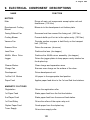
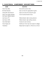
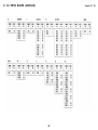
9. ELECTRICAL COMPONENT DESCRIPTIONS
FUNCTION
NAME
MOTORS
Main
Drives all main unit components except optics unit and
fans/blower. (100 Vac)
Development Cooling
Blower
Blows air to the development unit bottom plate.
Fusing Exhaust Fan
Removes heat from around the fusing unit. (100 Vac)
Cooling Blower
Prevents build up of hot air in the optics cavity. (100 Vac)
Vacuum Fan
Provides suction so paper is held firmly on the transport
belt. (100 Vac)
Scanner Drive
Drives the scanner. (dc servo)
Lens Drive
Positions the lens. (dc stepper)
4th/5th Mirror Drive
Positions the 4th/5th mirror assembly. (dc stepper)
Jogger
Drives the jogger plates to keep paper evenly stacked on
the duplex tray.
Cleaner Motors
Clean charge and separation wires.
Charge Fan
Ensures even charge on the surface of the drum.
Development
Drives development unit.
1st/2nd Lift Motors
Lift paper to the appropriate feed position.
Paper Feed
Applies paper feed drive to the 1st and 2nd feed stations.
MAGNETIC CLUTCHES
Registration
Drives the registration roller
1st Paper Feed
Starts paper feed from the first feed station.
2nd Paper Feed
Starts paper feed from the second feed station.
1st Feed Relay
Drives the rollers of the copier relay unit.
Duplex Paper Feed
Feeds paper from the duplex tray.
Toner Supply
Drives toner supply roller.
1-23
31 August 1989
SOLENOIDS
Cleaning
Moves the cleaning blade against the drum.
Pick-off
Moves the pick-off pawls against the drum.
Junction Gate
Energizes to direct copies to the duplex tray.
Duplex Positioning
Raises and lowers the sponge roller.
Manual Feed
Raises the pick-up roller when paper is fed from the manual
feed table.
1st and 2nd Fork Gate
In unison, open and close the appropriate fork gates
according to paper size.
Duplex Pick-up
Starts feed from duplex and aids the stopper solenoid.
Duplex Positioning
Lowers positioning roller.
Inverter Pressure
Controls the inverter pressure roller.
Duplex Stopper
Stops copy in the jogger unit.
1st/2nd Pick-up
Starts paper feed from the cassettes.
SWITCHES
Main
Supplies power to the copier.
Front Door Safety
Cuts ac power line.
Transport Unit Safety
Cuts 24-volt lines.
Fork Gate Unit Safety
Cuts 24-volt lines.
SENSORS
Pulse Generator
Supplies timing pulses to the main board.
Exit
Detects misfeeds.
Oil End
Detects the low oil condition.
Toner Overflow
Detects when the used toner bottle is full.
Toner End
Detects when it is time to add toner.
Registration
Detects misfeeds.
Manual Feed
Detects when the manual feed table is open.
Scanner Home
Informs the CPU when the scanner is at the home position.
1-24
31 August 1989
Lens Home
Informs the CPU when the lens is at the full size position.
4th/5th Mirror Home
Informs the CPU when the 4th/5th mirror assembly is at
the full size position.
1st Paper Size
Detects the paper size in the first cassette.
1st Paper End
Informs the CPU when the first cassette runs out of paper.
2nd Paper Size
Detects the paper size in the second cassette.
2nd Paper End
Informs the CPU when the second cassette runs out of
paper.
Scanner Overrun
Informs the CPU, if the scanner overshoots the home
position.
1st Relay
Detects misfeeds.
Jogger Home
Informs the CPU when the jogger plates are at the home
position.
Duplex Paper
Detects whether or not paper is on the duplex tray.
Duplex Entrance
Misfeed detector
Image Density
Detects the density of the image on the drum.
Auto Density (AD)
Senses the background density of the original.
CC Cleaner Home Position
Informs the CPU when the charge wire cleaner has
reached home position.
SC Cleaner Home Position
Informs the CPU when the separation wire cleaner has
reached home position.
Platen Cover
Informs the CPU that the platen cover is up or down.
Manual Feed Paper End
Informs the CPU that there is no paper in the manual feed
tray.
Fusing Exit
Detects misfeeds.
Inverter Exit
Detects misfeeds.
1st Lift
Detects whether paper has been raised to the proper paper
feed position.
2nd Lift
Detects whether paper has been raised to the proper paper
feed position.
1-25
31 August 1989
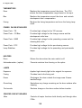
THERMISTORS
Drum
Monitors the temperature around the drum. The CPU
selects the bias compensation range based on its input.
Bias
Monitors the temperature around the drum and controls
development bias compensation.
Fusing
Monitors the fusing temperature and turns the fusing lamp
on/off.
POWER PACKS/STABILIZER
Power Pack - T/S
Provides high voltage for the T/S coronas.
Power Pack - CC/Bias
Provides high voltage for the charge corona and the
development roller bias.
Power Pack - Q/BR
Provides high voltage for the quenching corona and the
cleaning bias roller.
Power Pack - PCC
Provides high voltage for the pre-cleaning corona.
Lamp Stabilizer
Provides high voltage for the quenching and pre-transfer
lamps.
HEATERS
Drum
Warms the drum when the main switch is off.
Anticondensation (option)
Prevents moisture from forming on the optics.
LAMPS
Exposure
Applies high intensity light to the original for exposure.
Fusing
Provides heat to the fusing unit.
Erase
Discharges the drum outside the image area. Erases
lead/trail edge.
Quenching
Neutralizes any charge remaining on the drum surface after
cleaning.
Pre-transfer
Reduces charge on the drum surface before transfer.
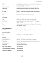
PRINTED CIRCUIT BOARDS
Main
Controls all copier functions both directly and through other
PCBs.
1-26
31 August 1989
Optics
Controls the speed of the scanner, the position of the lens,
and the position of the mirrors.
Operation Panel
Controls the LED matrix, and monitors the key matrix.
Paper Feed
Interfaces with overall paper feed; receives input from
paper size and paper end sensors.
AC Drive
Drives all ac motors, the exposure lamp, and the fusing
lamp.
Timer
Controls weekly timer and timer functions.
COUNTERS
Total
Keeps track of the total number of copies made.
A3/11” x 17”
Keeps track of the total number of A3/11” x 17” copies
made. (Option)
Key
Used for control of authorized use. Copier will not operate
until installed. (Option)
CIRCUIT BREAKERS
Circuit Breaker
Guards against voltage surges in the input power.
TRANSFORMERS
Main
Steps down the wall voltage to 100 Vac.
OTHERS
Power Supply Unit
Rectifies 100 Vac input and outputs dc voltages.
Thermofuse
Provides back-up overheat protection in the fusing unit.
AC Power Relay
Controls main power.
Noise Filter
Removes electrical noise.
Main Motor Capacitor
Start capacitor
Development Motor Capacitor
Start capacitor
Paper Feed Capacitor
Start capacitor
1-27
31 August 1989
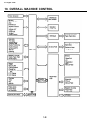
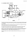
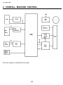
10. OVERALL MACHINE CONTROL
1-28
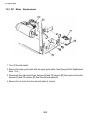
31 August 1989
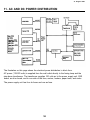
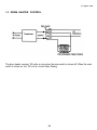
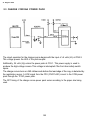
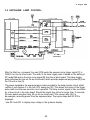
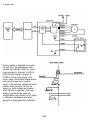
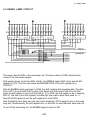
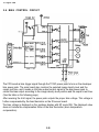
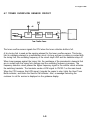
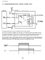
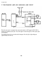
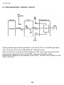
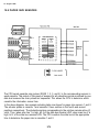
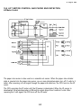
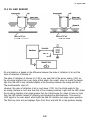
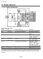
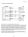
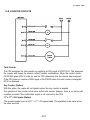
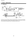
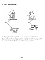
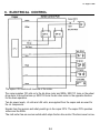
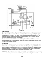
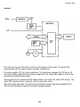
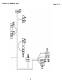
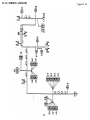
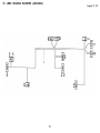
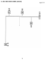
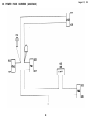
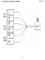
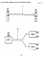
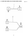
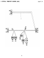
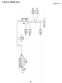
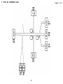
11. AC AND DC POWER DISTRIBUTION
The illustration on this page shows the electrical power distribution in block form.
AC power (115/220 volts) is supplied from the wall outlet directly to the fusing lamp and the
step-down transformer. The transformer supplies 100 volts ac to the power supply unit, SSR
board, ac drive board, and to one side of the fans, motors, heaters, paper bank, and sorter.
The power supply unit has four dc fuses and one ac fuse.
1-29
SECTION 2
DETAILED SECTION
DESCRIPTIONS
Contents
DETAILED SECTION DESCRIPTIONS
1. DRUM . . . . . . . . . . . . . . . . . . . . . . . . . . . . . . . . . . . . . . . . . . . . . . . . 2-1
1.1 SELENIUM DRUM CHARACTERISTICS . . . . . . . . . . . . . . . . . . . . . . . . . . . . . . . . . 2-1
1.2 HANDLING THE DRUM . . . . . . . . . . . . . . . . . . . . . . . . . . . . . . . . . . . . . . . . . . . . . . 2-1
1.3 DRUM HEATER CONTROL . . . . . . . . . . . . . . . . . . . . . . . . . . . . . . . . . . . . . . . . . . . 2-3
2. DRUM CHARGE . . . . . . . . . . . . . . . . . . . . . . . . . . . . . . . . . . . . . . . . 2-4
2.1 OVERVIEW . . . . . . . . . . . . . . . . . . . . . . . . . . . . . . . . . . . . . . . . . . . . ., . . . . . . . . . . 2-4
2.2 WlRE CLEANER . . . . . . . . . . . . . . . . . . . . . . . . . . . . . . . . . . . . . . . . . . . . . . . . . . . . 2-5
2.3 CHARGE CORONA POWER PACK . . . . . . . . . . . . . . . . . . . . . . . . . . . . . . . . . . . . . 2-6
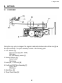
3. OPTICS . . . . . . . . . . . . . . . . . . . . . . . . . . . . . . . . . . . . . . . . . . . . . . . 2-7
3.1 OVERVIEW . . . . . . . . . . . . . . . . . . . . . . . . . . . . . . . . . . . . . . . . . . . . . . . . . . . . . . . . 2-7
3.2 EXPOSURE LAMP CONTROL . . . . . . . . . . . . . . . . . . . . . . . . . . . . . . . . . . . . . . . . . 2-9
3.3 SCANNER DRIVE . . . . . . . . . . . . . . . . . . . . . . . . . . . . . . . . . . . . . . . . . . . . . . . . . . 2-10
3.4 SCANNER MOTOR CONTROL . . . . . . . . . . . . . . . . . . . . . . . . . . . . . . . . . . . . . . . 2-11
3.5 LENS/MIRROR POSlTlONING . . . . . . . . . . . . . . . . . . . . . . . . . . . . . . . . . . . . . . . . 2-12
3.6 FOURTH AND FlFTH MIRROR ASSEMBLY . . . . . . . . . . . . . . . . . . . . . . . . . . . . . . 2-15
3.7 ORIGlNAL SlZE DETECTION . . . . . . . . . . . . . . . . . . . . . . . . . . . . . . . . . . . . . . . . . 2-17
3.8 RELATED SERVICE CALL CONDITIONS . . . . . . . . . . . . . . . . . . . . . . . . . . . . . . . . 2-17
4. ERASE . . . . . . . . . . . . . . . . . . . . . . . . . . . . . . . . . . . . . . . . . . . . . . . 2-22
4.1 OVERVIEW . . . . . . . . . . . . . . . . . . . . . . . . . . . . . . . . . . . . . . . . . . . . . . . . . . . . . . . 2-22
4.2 LEAD EDGE AND TRAILING EDGE ERASE . . . . . . . . . . . . . . . . . . . . . . . . . . . . . 2-23
4.3 SIDE ERASE . . . . . . . . . . . . . . . . . . . . . . . . . . . . . . . . . . . . . . . . . . . . . . . . . . . . . . 2-23
4.4 EDGE ERASE FUNCTION . . . . . . . . . . . . . . . . . . . . . . . . . . . . . . . . . . . . . . . . . . . 2-24
4.5 ERASE LAMP CIRCUIT . . . . . . . . . . . . . . . . . . . . . . . . . . . . . . . . . . . . . . . . . . . . . . 2-25
5. DEVELOPMENT . . . . . . . . . . . . . . . . . . . . . . . . . . . . . . . . . . . . . . . 2-26
5.1 OVERVIEW . . . . . . . . . . . . . . . . . . . . . . . . . . . . . . . . . . . . . . . . . . . . . . . . . . . . . . . 2-26
5.2 DEVELOPER EXCHANGE UNIT . . . . . . . . . . . . . . . . . . . . . . . . . . . . . . . . . . . . . . . 2-27
5.3 DRIVE MECHANlSM . . . . . . . . . . . . . . . . . . . . . . . . . . . . . . . . . . . . . . . . . . . . . . . . 2-28
5.4 IMAGE DENSlTY CONTROL . . . . . . . . . . . . . . . . . . . . . . . . . . . . . . . . . . . . . . . . . 2-30
5.6 BIAS CONTROL CIRCUIT . . . . . . . . . . . . . . . . . . . . . . . . . . . . . . . . . . . . . . . . . . . . 2-36
5.7 RELATED SERVlCE CALL CONDlTIONS . . . . . . . . . . . . . . . . . . . . . . . . . . . . . . . . 2-37
6. TONER DENSITY DETECTION AND TONER SUPPLY . . . . . . . . . 2-38
6.1 TONER SUPPLY . . . . . . . . . . . . . . . . . . . . . . . . . . . . . . . . . . . . . . . . . . . . . . . . . . . 2-38
6.2 BOTTLE DRIVE MECHANISM . . . . . . . . . . . . . . . . . . . . . . . . . . . . . . . . . . . . . . . . 2-39
6.3 TONER DENSITY DETECTION . . . . . . . . . . . . . . . . . . . . . . . . . . . . . . . . . . . . . . . 2-40
6.4 TONER DENSITY CONTROL . . . . . . . . . . . . . . . . . . . . . . . . . . . . . . . . . . . . . . . . . 2-41
6.5 TONER SUPPLY AMOUNT . . . . . . . . . . . . . . . . . . . . . . . . . . . . . . . . . . . . . . . . . . . 2-42
6.6 TONER END DETECTION . . . . . . . . . . . . . . . . . . . . . . . . . . . . . . . . . . . . . . . . . . . 2-44
6.7 TONER OVERFLOW SENSOR CIRCUIT . . . . . . . . . . . . . . . . . . . . . . . . . . . . . . . . 2-45
7. lMAGE TRANSFER AND PAPER SEPARATION . . . . . . . . . . . . . . 2-46
7.1 PRE-TRANSFER LAMP (PTL) . . . . . . . . . . . . . . . . . . . . . . . . . . . . . . . . . . . . . . . . . 2-46
7.2 IMAGE TRANSFER . . . . . . . . . . . . . . . . . . . . . . . . . . . . . . . . . . . . . . . . . . . . . . . . . 2-47
7.3 PAPER SEPARATION . . . . . . . . . . . . . . . . . . . . . . . . . . . . . . . . . . . . . . . . . . . . . . . 2-49
7.4 TRANSFER/SEPARATION CORONA POWER PACK . . . . . . . . . . . . . . . . . . . . . . 2-50
7.5 PICK-OFF MECHANISM . . . . . . . . . . . . . . . . . . . . . . . . . . . . . . . . . . . . . . . . . . . . . 2-52
7.6 PICK-OFF TIMING . . . . . . . . . . . . . . . . . . . . . . . . . . . . . . . . . . . . . . . . . . . . . . . . . . 2-53
7.7 PRE-TRANSFER LAMPAND QUENCHING LAMP CIRCUIT . . . . . . . . . . . . . . . . . 2-54
8. DRUM CLEANING . . . . . . . . . . . . . . . . . . . . . . . . . . . . . . . . . . . . . 2-55
8.1 OPERATION . . . . . . . . . . . . . . . . . . . . . . . . . . . . . . . . . . . . . . . . . . . . . . . . . . . . . . 2-55
8.2 PRE-CLEANING CORONA AND BIAS ROLLER . . . . . . . . . . . . . . . . . . . . . . . . . . 2-56
8.3 DRIVE MECHANISM . . . . . . . . . . . . . . . . . . . . . . . . . . . . . . . . . . . . . . . . . . . . . . . . 2-57
8.4 CLEANING BLADE . . . . . . . . . . . . . . . . . . . . . . . . . . . . . . . . . . . . . . . . . . . . . . . . . 2-58
8.5 CLEANING SOLENOID CIRCUIT. . . . . . . . . . . . . . . . . . . . . . . . . . . . . . . . . . . . . . 2-59
8.6 PRE-CLEANING CORONA CIRCUIT . . . . . . . . . . . . . . . . . . . . . . . . . . . . . . . . . . . 2-60
9. QUENCHING . . . . . . . . . . . . . . . . . . . . . . . . . . . . . . . . . . . . . . . . . . 2-61
9.1 OPERATION . . . . . . . . . . . . . . . . . . . . . . . . . . . . . . . . . . . . . . . . . . . . . . . . . . . . . . 2-61
9.2 PRE-QUENCHING CORONA CIRCUIT . . . . . . . . . . . . . . . . . . . . . . . . . . . . . . . . . 2-62
10. PAPER FEED . . . . . . . . . . . . . . . . . . . . . . . . . . . . . . . . . . . . . . . . . 2-63
10.1 OVERVIEW . . . . . . . . . . . . . . . . . . . . . . . . . . . . . . . . . . . . . . . . . . . . . . . . . . . . . . 2-63
10.2 LIFT MECHANISM AND PAPER END DETECTION . . . . . . . . . . . . . . . . . . . . . . 2-64
10.3 ROLLER FUNCTION . . . . . . . . . . . . . . . . . . . . . . . . . . . . . . . . . . . . . . . . . . . . . . . 2-66
10.4 SLIP CLUTCH MECHANISM . . . . . . . . . . . . . . . . . . . . . . . . . . . . . . . . . . . . . . . . 2-68
10.5 PAPER FEED DRIVE . . . . . . . . . . . . . . . . . . . . . . . . . . . . . . . . . . . . . . . . . . . . . . . 2-69
10.6 MANUAL FEED . . . . . . . . . . . . . . . . . . . . . . . . . . . . . . . . . . . . . . . . . . . . . . . . . . . 2-71
10.7 RELAY FEED AND REGISTRATION . . . . . . . . . . . . . . . . . . . . . . . . . . . . . . . . . . . 2-72
10.8 PAPER SIZE SENSORS . . . . . . . . . . . . . . . . . . . . . . . . . . . . . . . . . . . . . . . . . . . . 2-74
10.9 LIFT MOTOR CONTROL AND PAPER END DETECTION . . . . . . . . . . . . . . . . . . 2-75
11. PAPER TRANSPORT . . . . . . . . . . . . . . . . . . . . . . . . . . . . . . . . . . 2-77
11.1 OVERVIEW . . . . . . . . . . . . . . . . . . . . . . . . . . . . . . . . . . . . . . . . . . . . . . . . . . . . . . 2-77
11.2 TRANSPORT UNIT RELEASE MECHANISM . . . . . . . . . . . . . . . . . . . . . . . . . . . . 2-78
12. IMAGE FUSING AND PAPER EXIT . . . . . . . . . . . . . . . . . . . . . . . 2-79
12.1 OVERVIEW . . . . . . . . . . . . . . . . . . . . . . . . . . . . . . . . . . . . . . . . . . . . . . . . . . . . . . 2-79
12.2 FUSING DRIVE MECHANISM . . . . . . . . . . . . . . . . . . . . . . . . . . . . . . . . . . . . . . . 2-80
12.3 ENTRANCE GUIDE . . . . . . . . . . . . . . . . . . . . . . . . . . . . . . . . . . . . . . . . . . . . . . . . 2-81
12.4 OIL SUPPLY AND CLEANlNG . . . . . . . . . . . . . . . . . . . . . . . . . . . . . . . . . . . . . . . 2-82
12.5 OIL END SENSOR . . . . . . . . . . . . . . . . . . . . . . . . . . . . . . . . . . . . . . . . . . . . . . . . 2-83
12.6 FUSlNG EXlT ASSEMBLY . . . . . . . . . . . . . . . . . . . . . . . . . . . . . . . . . . . . . . . . . . 2-84
12.7 FUSING CONTROL . . . . . . . . . . . . . . . . . . . . . . . . . . . . . . . . . . . . . . . . . . . . . . . . 2-85
12.8 SERVlCE CALL CONDlTIONS . . . . . . . . . . . . . . . . . . . . . . . . . . . . . . . . . . . . . . . 2-88
13. PAPER EXIT . . . . . . . . . . . . . . . . . . . . . . . . . . . . . . . . . . . . . . . . . 2-90
13.1 OVERVIEW . . . . . . . . . . . . . . . . . . . . . . . . . . . . . . . . . . . . . . . . . . . . . . . . . . . . . . 2-90
13.2 EXIT ROLLER DRlVE MECHANlSM . . . . . . . . . . . . . . . . . . . . . . . . . . . . . . . . . . 2-91
14. DUPLEX . . . . . . . . . . . . . . . . . . . . . . . . . . . . . . . . . . . . . . . . . . . . . 2-92
14.1 INVERSION . . . . . . . . . . . . . . . . . . . . . . . . . . . . . . . . . . . . . . . . . . . . . . . . . . . . . 2-92
14.2 DUPLEX TRANSPORT . . . . . . . . . . . . . . . . . . . . . . . . . . . . . . . . . . . . . . . . . . . . . 2-96
14.3 DUPLEX STACKING . . . . . . . . . . . . . . . . . . . . . . . . . . . . . . . . . . . . . . . . . . . . . . . 2-99
14.4 DUPLEX TRAY SENSORS . . . . . . . . . . . . . . . . . . . . . . . . . . . . . . . . . . . . . . . . . 2-103
14.5 DUPLEX PAPER FEED . . . . . . . . . . . . . . . . . . . . . . . . . . . . . . . . . . . . . . . . . . . . 2-104
14.6 RELATED SERVICE CALL CONDlTlONS . . . . . . . . . . . . . . . . . . . . . . . . . . . . . . 2-107
15. OTHER CIRCUITS . . . . . . . . . . . . . . . . . . . . . . . . . . . . . . . . . . . 2-108
15.1 DC POWER DISTRIBUTION . . . . . . . . . . . . . . . . . . . . . . . . . . . . . . . . . . . . . . . . 2-108
15.2 SAFETY SWITCH ClRCUITS . . . . . . . . . . . . . . . . . . . . . . . . . . . . . . . . . . . . . . . . 2-109
15.3 AC COMPONENT CONTROL . . . . . . . . . . . . . . . . . . . . . . . . . . . . . . . . . . . . . . . 2-110
15.4 CORONA CLEANER MOTORS . . . . . . . . . . . . . . . . . . . . . . . . . . . . . . . . . . . . . . . 2-111
15.5 PULSE GENERATOR . . . . . . . . . . . . . . . . . . . . . . . . . . . . . . . . . . . . . . . . . . . . . 2-112
15.6 MAGNETIC CLUTCH AND SOLENOID CONTROL . . . . . . . . . . . . . . . . . . . . . . 2-113
15.7 SENSOR OPERATION . . . . . . . . . . . . . . . . . . . . . . . . . . . . . . . . . . . . . . . . . . . . 2-114
15.8 COUNTER ClRCUITS . . . . . . . . . . . . . . . . . . . . . . . . . . . . . . . . . . . . . . . . . . . . . 2-117
31 August 1989
1. DRUM
1.1 SELENIUM DRUM CHARACTERISTICS
Selenium has the following characteristics:
• Accepts a high positive electrical charge in the dark. (The electrical resistance of selenium
is high in the absence of light.)
• Dissipates the electrical charge when exposed to light. (Exposure to light greatly enhances
the conductivity of selenium.)
• Dissipates the electrical charge in direct proportion to the intensity of the light.
That is, where stronger light is directed to the selenium surface, a smaller voltage
remains on the selenium.
The sensitivity of selenium changes slightly with variations in the surface temperature of the
drum. (Under cool conditions, the drum conductivity decreases. This will result in background
or excessive image density.) As a countermeasure, the development bias is changed to
compensate for temperature variations around the drum. Also, while the copier is off, the drum
heater warms the drum.
Drum sensitivity also depends on how long the drum has rested between copy runs. The
copier’s CPU compensates for changes in drum sensitivity due to rest time by changing the
development bias. This prevents variations in image density at the beginning of copy runs.
The selenium drum used in this model has high sensitivity, good color reproduction, and good
reproduction of low contrast originals (pencil originals, etc.)
1.2 HANDLING THE DRUM
Never touch the drum surface with bare hands.
Store the drum in a cool, dry place away from heat.
When cleaning the drum, always wear a pair of gloves. Do not throw away cotton
used for cleaning. Bring it back to the service depot for disposal according to local
regulations.
Prime the drum with setting powder when the drum, cleaning blade, or cleaning brush are
replaced. Do this within one minute in a location not exposed to strong light.
2-1
31 August 1989
• Drum conditioning is necessary when a new drum is installed. In addition, it should
be done at the following times:
1) When image density is reduced due to overexposure of the drum
2) After cleaning the drum
3) When the oxide layer on the drum is lightly scratched
• When installing or removing the drum, always keep it in the protective sleeve.
• Before installing or removing the drum, pull out the cleaning unit part way so that the
pick-off pawls do not scratch the drum surface.
• Before placing the protective sleeve on the drum while it is in the copier, always take out
the development unit. Otherwise, the edge of the sleeve will scrape developer from the
development roller.
2-2
31 August 1989
1.3 DRUM HEATER CONTROL
The drum heater receives 100 volts ac only when the main switch is turned off. When the main
switch is turned on, the 100 volt ac current stops flowing.
2-3
31 August 1989
2. DRUM CHARGE
This copier uses a dual wire corotron unit and a highly sensitive selenium drum. The corona
wires [A] generate a flow of positive ions when the charge power pack applies a high positive
voltage to the corona unit. The drum coating [B] receives a uniform positive charge as it
rotates past the corona unit.
The charge fan [C] provides a smooth flow of air to the interior of the charge corona unit [D]
to prevent uneven build up of positive ions. (An uneven build up of positive ions could cause
uneven image density.)
2-4
31 August 1989
2.2 WIRE CLEANER
Paper dust or toner particles on the corona wires [A] may interfere with charging. The wire
cleaner [B] corrects this problem by automatically wiping the charge corona wires clean. Pads
on the wire cleaner bracket clean the corona wires as the dc motor [C] drives the cleaner
bracket from the home position to the rear end of the corona unit and then back again.
Operation of the wire cleaner is based on copy count. A RAM counter keeps track of the
number of copies made since the last time the wires were cleaned. The CPU checks this
counter each time the copier is turned on. If the count is greater than 5,000 at that time, the
CPU turns on the cleaner motor to clean the corona wires. Simultaneously, it resets the
counter to zero.
During a cleaning cycle, the cleaner motor drives the wire cleaner toward the rear endblock.
Normally, the cleaner reaches the rear endblock in about 10 seconds, but the motor stays on
for 20 seconds to ensure that the cleaner moves the full distance. Then, the motor reverses to
drive the wire cleaner to the home position. The motor turns off when the cleaner activates the
home position sensor [D]. If the home position sensor is not activated within 20 seconds after
reverse drive is initiated, the CPU stops the motor and adds 1 to the count stored in SP mode
121 (SC85 and 86). Copies can still be made and there is no service call indication on the
operation panel.
Note:
SC 85 –> The home position sensor does not turn ON.
SC 86 –> The home position sensor does not turn OFF.
2-5
31 August 1989
2.3 CHARGE CORONA POWER PACK
The circuit operation for the charge corona begins with the input of +5 volts (Vc) at CN2-3.
This voltage powers the LED of the photocoupler.
Additionally, 24 volts (Vp) enters the power pack at CN1-1. This power supply is used to
produce the high voltage corona. This voltage is interrupted if the front door safety switch
opens.
The charge corona turns on 260 milliseconds before the lead edge of the copy is detected by
the registration sensor. A LOW signal from the CPU (CN101-A20) is sent to the CC/B power
pack through the TC/SC power pack.
The OFF timing of the charge corona power pack varies according to the paper size being
used.
2-6
31 August 1989
3. OPTICS
3.1 OVERVIEW
During the copy cycle, an image of the original is reflected onto the surface of the drum [I] via
the optics assembly. The optics assembly consists of the following parts:
1. First Scanner [A]:
Exposure lamp [B] (85V, 160W)
First mirror
AD (Auto Density) sensor [C]
2. Second Scanner [D]:
Second mirror
Third mirror
3. Lens (F5, f = 215 mm) [E]
4. Fourth and Fifth Mirror Assembly [F]:
Fourth Mirror
Fifth Mirror
5. Sixth Mirror [G]:
6. Toner Shield Glass [H]
2-7
31 August 1989
This copier has nine standard reproduction ratios: five reductions, three enlargements and full
size. In addition, it has a zoom function. The reproduction ratio can be selected in one
percent steps from 60% to 155%.
A servomotor drives the first and second scanners during the copy cycle. This motor is
controlled by the optics PCB, which changes the motor speed depending on the reproduction
ratio. Two stepper motors change the position of the lens and the fourth and fifth mirror
assembly to change the reproduction ratio. The sixth mirror is fixed.
The fiber optic cable used for the auto density sensor (ADS) is mounted on the first scanner.
The ADS collects light reflected from the original in auto density sensing mode.
2-8
31 August 1989
3.2 EXPOSURE LAMP CONTROL
After the Start key is pressed, the main PCB sends the exposure lamp trigger signal [C] to
CN501-6 on the ac drive board. The width of the lamp trigger pulse is based on the setting of
SP mode #48 and on the zero-cross signal [B] from the ac drive board. This lamp trigger
pulse activates the triac on the ac drive board, which provides exposure lamp power [D] from
the 100-volt ac line [A].
The power supplied to the exposure lamp is also provided to the lamp monitor circuit, which
rectifies it and supplies it to the Sub CPU analog port [E]. This allows fine tuning of the trigger
pulse width and ensures accurate circuit operation. The lamp monitor signal is also monitored
by a timer circuit in the main board. Should this signal stay active for longer than 15 seconds,
the main board energizes relay RA on the ac drive board. This causes relay RA1 to
de-energize, removing power from the exposure lamp. The copier stops and SC #12 is
displayed.
Use SP mode #51 to display lamp voltage in the guidance display.
2-9
31 August 1989
3.3 SCANNER DRIVE
This model uses a dc servomotor [A] to drive the first [B] and second [C] scanners.
This first scanner is attached to the scanner drive wire by the wire clamp [D]. The second
scanner is connected to the scanner drive wire by a movable pulley [E] (the second scanner
pulley).
The second scanner pulley moves the second scanner at half the velocity of the first scanner.
This maintains the focal distance between the original and the lens during scanning. This
relationship can be expressed as follows:
V1r = 2(V2r) = VD/r
where
r:
V1r:
V2r:
VD:
Reproduction
First Scanner Velocity (when the Reproduction ratio is “r”)
Second Scanner Velocity (when the Reproduction ratio is “r”)
Drum Peripheral Velocity (300 mm/s)
The first scanner wire clamp also actuates the home position sensor. The CPU on the optics
board controls both the registration and return timing.
2-10
31 August 1989
3.4 SCANNER MOTOR CONTROL
The scanner drive motor is a dc servomotor. The CPU on the optics board controls the speed
of this servomotor. The main CPU and the optics CPU communicate through a serial interface
bus (TXD/RXD).
After the main CPU sends the scanner start signal to the optics CPU, the optics CPU receives
the drum speed data from the main PCB (pulse generator).
An encoder on the servomotor has two magnetic sensors that generate two pulse signals.
The optics CPU monitors the scanner speed and direction by these pulse signals.
Based on the drum speed and encoder data, the optics CPU determines the proper speed for
the scanner drive motor to obtain proper vertical magnification. The optics CPU sends the
speed data to the timer IC, which controls the scanner motor circuit.
The home position sensor informs the optics board when the first scanner is in the home
position.
2-11
31 August 1989
3.5 LENS/MIRROR POSITIONING
Lens Drive
The lens drive motor (stepper motor) [A] changes the lens position according to the selected
reproduction ratio to provide the proper horizontal magnification between the lens and the
drum’s surface.
The output gear of the lens drive motor engages the gears [B] of the lens drive pulley. The
lens drive wire [C] is wrapped around the lens drive pulley and is connected to the lens drive
bracket [D]. The rotation of the lens drive pulley moves the lens back and forth in discrete
steps.
2-12
31 August 1989
[A] - Lens Drive Pulley
[B] - Lens Housing
The lens home position sensor [C] informs the optics PCB when the lens [D] is at the full-size
position (home position). The optics PCB determines the lens stop position in reduction and
enlargement modes by counting the number of steps from the home position. When the
reproduction ratio is changed, the lens moves directly to the selected magnification position.
2-13
31 August 1989
Home position is checked by moving
the lens from the enlargement side
towards the reduction side. So, when
home position is checked, a LOW to
HIGH to LOW signal is present at
CN305-9 of the optics board. This
occurs when the actuator blade enters
and exits the lens home position
sensor. The lens only references home
position when going to full size (at
power up, when modes are cleared,
when full size is selected.) The lens
always overshoots the selected
magnification ratio position by 40 steps
to eliminate mechanical play when
going from enlargement to reduction.
2-14
31 August 1989
3.6 FOURTH AND FIFTH MIRROR ASSEMBLY
When the reproduction ratio is changed, the stepper motor [A] moves the fourth and fifth
mirror assembly [B] using the wire [C] and pulleys [D]. This provides the proper focal
distance between the original and the drum.
When the fourth and fifth mirror assembly is in the full-size position, the actuator [E] on the
assembly actuates the fourth/fifth mirror home position sensor [F]. This signal goes to the
optics CPU.
2-15
31 August 1989
Fourth and Fifth Mirror Assembly Positioning
The mirror home position sensor informs the optics CPU when the fourth and fifth mirror
assembly is at the home position. The home position is determined by a LOW to HIGH to
LOW change on CN305-12 of the optics board.
When a reproduction ratio is selected, the operation panel PCB sends this information to the
main board. The main board then sends the appropriate trigger signals through the serial line
to the optics board.
When moving away from the home position, the mirror drive pulley turns clockwise and moves
directly to the selected position. However, when moving towards the home position (pulley
turns counterclockwise), the mirror assembly overshoots the selected position by 40 steps
(adjust by SP 47) and then returns to the selected position. This takes out any mechanical
play.
2-16
31 August 1989
3.7 ORIGINAL SIZE DETECTION
NOTE: With the F33\34, original size detection is performed using the OL and OW sensors in
the ARDF unit. For more information, see the ARDF options section.
3.8 RELATED SERVICE CALL CONDITIONS
Code #11: Exposure Lamp Malfunction
Definition:
Lights if the lamp filament breaks or if the lamp turns on during ready or please wait modes.
Observation:
When the main switch is turned on, call service code “11” is displayed.
Points to Check:
If the lamp is lit during the ready or please wait mode, check CN103-5 on the main PCB. If it is
not lit during the copy cycle, check CN501-6 on the main board. Check the exposure lamp.
Code #12: Lamp Relay Open
Definition:
Lights if the lamp stays on longer than 15 seconds during a copy cycle.
Observation:
The lamp remains lit when the scanner returns to the home position.
Points to Check:
Check CN102-A20, CN101-A24, and CN103-5 on the main PCB.
Code #21: Abnormal Encoder Pulse
Definition:
The scanner drive motor is energized until the scanner home position sensor is blocked. If the
scanner is not in the home position when the print key is pressed, an excessive number of
pulses from the encoder are received, and code 21 is illuminated.
Observation:
The scanner is out of home position when the print key is pressed.
Points to Check:
Check that the scanner is moving properly. Check CN306-2 and CN306-3 on the optics board.
Check the scanner drive wire and the scanner drive pulley screws.
2-17
31 August 1989
Code #22: Scanner Home Position Sensor Stays High
Definition:
Lights if the scanner home position sensor is open at power up.
Observation:
Scanner eventually moves to the extreme right as on/off key is activated until code 2d is
displayed.
Points to Check:
Check that the scanner is working properly. Check CN305-3 on the optics board.
Code #24: No Home Position Signal
Definition:
Lights if the main board does not receive the H.P. signal from the optics board within 20
seconds after the scanner return signal.
Observation:
Code 24 is displayed 20 seconds after power-up.
Points to Check:
Check CN106-5 and 6 on the main PCB.
Check CN304-4 and 5 on the optics board.
Code #25: Scanner Home Position Sensor Stays Low
Definition:
Lights if the scanner home position sensor is shorted at power up.
Observation:
Scanner moves to the extreme left at power up.
Points to Check:
Check CN305-3 on the optics board.
2-18
31 August 1989
Code #28: Lens Home Position Sensor Stays Low
Definition:
Lights if the lens is moving toward enlargement and the H.P. sensor stays at a LOW signal
level for longer than 3.82 seconds.
Observations:
The lens always moves toward enlargement at power-up. The lens is to the right of the H.P.
sensor and the lens motor does not turn on.
Points to Check:
Check if the lens is moving properly. Check CN305-9 on the optics board. Check the lens
drive section, optics board, and lens drive motor.
Code #29: Lens Home Position Sensor Stays High
Definition:
Lights if the lens is moving toward reduction and the H.P. sensor stays at a high signal level
longer than 3.82 seconds.
Observations:
The lens always moves toward reduction at power-up. The lens is to the left of the H.P. sensor
and the lens motor does not turn on.
Points to Check:
Confirm that the lens is moving properly. Check CN305-9 on the optics board. Check the lens
drive section, optics board, and lens drive motor.
2-19
31 August 1989
Code #2A: 4th/5th Mirror Home Position Sensor Stays Low
Definition:
Lights when the 4th/5th mirror sensor home position sensor does not actuate within 1.83
seconds after the mirror motor turns on.
Observations:
At power-up, the 4th/5th mirror drive rotates counterclockwise past the home position sensor.
If the main switch is turned off and on, the mirror motor emits a noise and stays at the home
position.
Points to Check:
Confirm that the 4th/5th mirror assembly is moving properly. Check CN305-12 on the optics
board. Check the 4th/5th mirror section, optics board, and mirror drive motor.
Code #2B: 4th/5th Mirror Sensor Stays High
Definition:
Lights if the 4th/5th mirror home position sensor remains actuated for 1.83 seconds after the
mirror motor turns on.
Observations:
At power-up, the 4th/5th mirror drive rotates clockwise and the actuator leaves the home
position sensor. If the main switch is turned off and on, the drive pulley continues to drive in a
clockwise direction until the mirror motor emits a noise and stops at the extreme right.
Points to Check:
Confirm that the second scanner moves properly. Check CN305-12 on the optics board.
Check the 4th/5th mirror section, optics board, and mirror drive motor.
2-20
31 August 1989
Code #2D: No Encoder Output
Definition:
Lights durnig a copy cycle when the output frequency from the scanner motor encoder is not
detected for 490 milliseconds after the scanner motor is energized or if the scanner home
position sensor opens or shorts during a copy cycle.
Observation:
During a copy cycle the scanner first moves then stops. The scanner does not move at all.
Points to Check:
Check the scanner drive motor, the scanner home position sensor, and CN306-2, 3 on the
optics board.
2-21
31 August 1989
4. ERASE
4.1
A:
Lead Edge Erase Margin
B:
Side Margins --- 2 ± 2 mm each (For full-size copies the total of both side
margins is less than 4 mm.)
Lo:
Original Image Width
Lc:
Charged Width on the Drum
El:
Lead Edge Erase
Es:
Side Erase
R:
Paper Lead Edge Registration --- 0 ± 2 mm
A+R:
Lead Edge Blank Margin --- 3.5 ± 2.5 mm
The erase unit consists of a PCB with 10 registers and a row of 80 LEDs mounted in a plastic
casing. The LEDs emit light in the yellow-green part of the spectrum.
The erase lamp performs the following functions: lead edge erase, side erase, trail edge erase,
image density pattern [g], and the editing functions. Trail edge erase begins after the trailing
edge of the copy paper; therefore, the trailing edge will not appear on the copy.
2-22
31 August 1989
4.2 LEAD EDGE AND TRAILING EDGE ERASE
The entire bank of erase lamps turns on to erase the drum before and after the image area.
Leading edge erase overlaps the paper and the image slightly. The leading edge margin helps
prevent fusing jams by making it easier for the stripper pawls to separate the paper from the
hot roller. Trailing edge erase turns on about 2 mm after the trailing edge of the copy paper.
The width of the lead edge margin can be adjusted by SP mode #41.
Mode No.
Function
Data
Factory
Setting
41 Lead Edge
Erase Margin
Adjustment
Adjusts the
lead edge
margin
0 - 15
8
Comments
0.6 mm per step
(max. -4.8 mm to
+4.2 mm)
During image density detection cycles (once every ten cycles), the center block of erase
lamps turns off long enough for the sensor pattern to be developed [g].
4.3 SIDE ERASE
Side erase overlaps the image slightly on either side. The CPU calculates the side erase
margins from the paper size and the selected reproduction ratio. As the paper is fed to the
center of the drum, the LEDs for side erase turn on in pairs. The erase lamp is not used for
side erase with A3 or 11 x 17 paper. For these paper sizes, side erase occurs due to the end
block covers of the charge corona.
The CPU adjusts the side erase margin to be as near as possible to the actual image size,
even when using the zoom function. However, since the erase lamp LEDs will not work in
precise one millimeter intervals, the side erase margin varies slightly depending on the
reproduction ratio.
SP 27 decreases the side margins by 5 mm.
2-23
31 August 1989
4.4 EDGE ERASE FUNCTION
The edge erase function erases a border around the copy. The border is adjustable in 4 steps
using SP mode #38. These borders are approximately 5, 10, 15, and 20 millimeters wide, but
vary slightly according to paper size and the selected reproduction ratio. The table shows the
ON/OFF condition of the erase lamp LEDs for the various paper sizes. The factory setting is 10
millimeters.
2-24
31 August 1989
4.5 ERASE LAMP CIRCUIT
This copier uses 80 LEDs in the erase lamp unit. The large number of LEDs allows precise
control of the side erase margins.
Shift register drivers control the LEDs. Initially, the ENABLE signal (LOW active) sets all shift
registers to OFF. Then the main board sends ERASE DATA to the shift registers from
CN102-A17.
After the ENABLE signal goes back to HIGH, the shift registers start accepting data. The data
bit for LED 1 is set at each CLOCK pulse. If the data line is HIGH at the time of the CLOCK
pulse, the shift register is set to turn the LED on; if it is LOW, the shift register is set to keep the
LED off. The data in the shift registers is shifted right one position each clock pulse; so, it
takes 80 CLOCK pulses to set the shift registers for all the LEDs.
After all data bits have been sent, the main board sends the LATCH signal to turn on the erase
lamp unit. Simultaneously, the shift registers turn on all LEDs for which data bits have been set.
To turn off the erase lamp unit, the ENABLE signal is reset to LOW.
2-25
31 August 1989
5. DEVELOPMENT
5.1 OVERVIEW
When the main motor sends a signal to the SSR PCB, the development motor is energized.
When it turns on, the paddle roller [A] and development roller [B] start turning. The paddle
roller picks up developer in its paddles and transports it to the development roller. Internal
permanent magnets in the development roller attract the developer to the development roller
sleeve. The turning sleeve of the development roller then carries the developer past the doctor
blade [C]. The doctor blade trims the developer to the desired thickness and creates backspill
to the crossmixing mechanism.
The development roller continues to turn, carrying the developer to the selenium drum [D].
When the developer brush contacts the drum surface, the positively charged areas of the
drum surface attract and hold the negatively charged toner. In this way, the latent image is
developed.
The development roller is given a positive bias to prevent toner from being attracted to the
non-image areas on the drum that may have residual positive charge. The bias controls image
density.
After turning another 100 degrees, the development roller releases the developer to the
developer tank.
The developer is agitated by the paddle roller and the crossmixing mechanism. The knocking
solenoid vibrates the upper cover of the developer unit to prevent toner buildup.
2-26
31 August 1989
5.2 DEVELOPER EXCHANGE UNIT
The developer exchange plate [A] enables the removal of developer from the development
unit. The developer inlet cover [B] enables the addition of developer to the development unit
without separating the toner tank from the development unit. SP87 sets the PM cycle. When a
predetermined count is reached, the service call indicator blinks, the guidance display
indicates “Call for maintenance”, and the start key stays green.
2-27
31 August 1989
5.3 DRIVE MECHANISM
A: Development Drive Gear
B: Development Roller Gear
C: Idle Gear
D: Auger Gear
The gears of the development unit and the toner agitator gear are driven by the development
drive gear [A] when the development motor turns. The rotation is transmitted as follows:
The development drive gear and development roller gear are helical gears. Helical gears are
more quiet than normal gears. The teeth of the development drive gear are chamfered so that
they smoothly engage with the development roller gear [B] when the unit is installed.
2-28
31 August 1989
5.4 CROSSMIXING
The crossmixing mechanism has two functions: it keeps the toner and developer evenly
mixed, and it helps to agitate the developer.
The developer that is attracted to the development roller at point [A] is split into two parts by
the doctor blade. One part [B] (the magnetic brush) goes on to develop the latent image on
the drum. However, the other part [C] is trimmed off by the doctor blade and directed to the
backspill plate [D].
As the developer slides down the backspill plate to the paddle roller, it is moved slightly toward
the front of the unit by the mixing vanes [E]. Part of the developer falls into the auger inlet [F]
and is transported to the rear of the unit by the mixing auger [G], where it drops onto the
paddle roller [H]. The amount of developer moved to the front by the mixing vanes and to the
rear by the mixing auger is equal.
2-29
31 August 1989
5.5 IMAGE DENSITY CONTROL
Image density is controlled in two ways: 1) by changing the strength of the bias voltage
applied to the development roller sleeve, and 2) by changing the strength of the voltage
applied to the exposure lamp.
Applying a bias voltage to the development sleeve reduces the potential between the
development roller and the drum, which reduces the amount of toner transferred; so, the
stronger the bias voltage, the lighter the copy image. Similarly, increasing the voltage to the
exposure lamp causes an increase in light intensity, which also results in lighter copies.
The control method is different depending on whether the image density is selected manually
or the automatic ID system is used.
Manual Image Density Control
DARK < - - - - - - - - - - - - - - - - - - - - - - - - - - - - - - - - - > LIGHT
ID Level
1
V1: Bias
260
V2: Lamp Vo-5
Voltage
2
260
Vo-3.5
3
260
Vo-1
4
290
Vo
5
290
Vo+2.5
6
320
Vo+3.5
7
350
Vo+4.5
Vo = 50 to 80 volts ac
When image density is set manually, the development bias (base level) and the exposure lamp
voltage vary as shown in the above table. The lamp voltage at ID level 4 (Vo) can be adjusted
with SP mode #48.
NOTE: In Auto ID mode, the lamp voltage remains at Vo (no compensation is applied).
2-30
31 August 1989
Auto Image Density Control
Leading edge of original
When automatic image density control is selected, the exposure lamp voltage is set at position
4. Image density is controlled only by changing the bias voltage.
At the start of the copy cycle the original sensing mechanism measures the background
density of the original image. It does this by measuring the strength of the light reflected from
a 48-mm strip. This strip starts 12 mm from the leading edge of the original. A fiber optic cable
pipes the reflected light to a photodiode on the main board. The photodiode is the input
element of the auto ID circuit.
2-31
31 August 1989
Auto ID Peak Hold Input Voltage
The CPU checks the voltage output by the auto ID circuit. This circuit has a peak hold
function. The peak hold voltage corresponds to the maximum reflectivity of the original. Based
on the peak hold voltage, the CPU determines the proper bias base level and sends a 4-bit
control signal to the power pack. The power pack then applies the proper bias to the
development roller.
SP 56
A new function has been added to enable the service engineers to quickly adjust for ADS
sensor discrepancies.
All ADS sensor functions are related to an ADS sensor value of 3.0 volts for white paper.
Previously if this value was incorrect the ADS functions might not have worked properly and
the variable resistor for the ADS sensor would have to be adjusted.
Now, using SP 56, a correction factor can be stored in memory so that if the ADS sensor
voltage is slightly out, the variable resistor does not have to be adjusted. (See ADS Reference
Voltage Setting.)
2-32
31 August 1989
Bias Compensation Factors
As discussed previously, the bias base level is set either by the automatic image density
system or by the operator through the image density keys. The CPU increases the base bias
level as necessary to compensate for the rest time between copy runs and the drum
temperature, both of which affect drum sensitivity.
1) Rest Time Compensation
10 - 20°C
1
2
Copies
3
4-5
6-10
0
0
30
0
0
0
4-5
6-10
0
30
30
60
0
0
30
30
Rest Time
0 - 3 min
3 - 50 min
50 - 2 hr
> 2 hr
Same as previous copy
30
0
30
30
30
30
60
30
30
20 - 45°C
1
2
Copies
3
Rest Time
0 - 10 sec
10 sec - 3 min
3 min - 50 min
50 min - 2 hr
> 2 hr
Same as previous copy
30
30
60
60
90
60
120
90
30
30
60
90
Note: Figures are in + Vdc.
The drum sensitivity often drops slightly over the first few cycles of a copy run. This is
because the light from the exposure lamp fatigues the drum slightly, and it takes a few copies
for the selenium to restabilize. The amount that the sensitivity drops depends on the rest time
between copy runs (the longer the rest time, the greater the change).
The time at which each copy cycle is completed is stored in RAM. The CPU references this
time data in RAM to determine the proper rest time bias compensation level for the next copy
cycle even after the main switch has been turned OFF and ON after a copy cycle. For time
data to be stored in RAM, the jumper connector on the timer PCB must be in the ON position.
The copier increases the bias at the beginning of each copy run to prevent variations in the
image density of the first few copies produced. The amount of bias increase is shown in the
above table.
If the drum temperature is less than 10° Celsius, no rest time compensation is applied.
2-33
31 August 1989
2) Drum Temperature Compensation
The CC/Bias power pack monitors drum temperature through a thermistor (TH-1), and it
increases or decreases the bias voltage to compensate for variations in drum sensitivity that
are induced by temperature changes in the drum cavity. At 30° Celcius (base temperature), no
drum temperature compensation is performed. For each 1° C rise in drum temperature, the
development bias is decreased 6V. For each 1° C fall in drum temperature, the development
bias is increased 6V.
2-34
31 August 1989
Bias For ID Sensing
In order to develop the ID sensor pattern consistently, the CPU applies a fixed base bias level
to the development roller at the beginning of the first copy after power-up, and then once
every ten copy cycles. Fixed base bias is factory set at 500 volts dc (adjusted by SP #33).
Compensation for drum cavity temperature and drum rest time is added to the fixed base bias.
The CPU applies the ID sensor fixed base bias to the development roller about 32 milliseconds
after the scanner starts forward scan. Just after the sensor pattern is developed, the CPU
changes the bias output to the level selected by the ID keys or auto ID system. The bias
output remains at this level until the scanner starts the return scan.
Toner concentration can be increased or decreased by changing the ID fixed base bias.
Higher fixed base bias will cause the sensor pattern to be developed lighter. The CPU then
senses that the toner level is low and therefore adds more toner. This results in darker copies
as toner concentration is increased.
SP #33
0
ID fixed base bias:
500
1
2
3
380
470
530
2-35
31 August 1989
5.6 BIAS CONTROL CIRCUIT
The CPU sends a bias trigger signal through the TC/SC power pack to turn on the developer
bias power pack. The main board also monitors the selected image density level and the
copier rest time, and it sends a 4-bit bias output control signal to the bias power pack to
control the bias output according to the image density level position and the copier’s rest time.
(See the table on the following page.)
After receiving the 4-bit signal, the power pack outputs the proper bias voltage. This voltage is
further compensated by the bias thermistor on the ID sensor board.
The bias voltage is displayed on the guidance display with SP mode #59. The displayed value
does not include the compensation factor of the bias thermistor (drum temperature
compensation).
2-36
31 August 1989
4-Bit Bias Control Signal
BIT 4
BIT 3
BIT 2
BIT 1
Bias Output
0
0
0
0
0
0
0
0
1
1
1
1
1
1
1
1
0
0
0
0
1
1
1
1
0
0
0
0
1
1
1
1
0
0
1
1
0
0
1
1
0
0
1
1
0
0
1
1
0
1
0
1
0
1
0
1
0
1
0
1
0
1
0
1
260
290
320
350
380
410
440
470
500
530
560
590
620
650
680
710
NOTE: SP34 shifts the bias under all conditions. There are three settings: 0, 60, and 120.
5.7 RELATED SERVICE CALL CONDITIONS
Code #31: Drum Thermistor Blown
Definition:
Lights when the drum thermistor circuit is open.
Points to Check:
Check the resistance between CN36-3 and CN36-D on the ID sensor board.
(Reference value: 10 kohms at 25°C)
Check CN103-13 on the main PCB.
2-37
31 August 1989
6. TONER DENSITY DETECTION AND TONER SUPPLY
6.1 TONER SUPPLY
The toner supply drive gear [A] turns when the development motor is on. The toner supply
clutch [B] applies the rotation from the toner supply drive gear to the toner supply roller gear
[C], which drives the agitator gear [D]. Toner catches in the grooves on the toner supply
roller [E]. Then, as the grooves turn past the opening, the toner drops into the development
unit.
The teeth on both the toner supply drive gear and the toner supply roller gear are chamfered.
2-38
31 August 1989
6.2 BOTTLE DRIVE MECHANISM
For easy access, the toner bottle is just inside the front cover. The bottle is positioned
horizontally.
The bottle drive mechanism transports toner from the bottle to the toner tank. A worm gear
[A] on the front end of the toner supply roller [B] drives this mechanism.
When the toner supply roller turns, the worm gear turns the toner bottle [C] via the worm
wheel, the bottle drive gear, and the bottle gear. The toner bottle has a spiral groove that
helps move toner to the toner inlet.
To prevent toner from scattering when the toner bottle is lowered, a rack [D] and pinion [E]
system closes the toner shutter [F].
At the toner inlet section, the toner agitator [G] has a spiral shape to move the toner to the
toner tank cavity.
2-39
31 August 1989
6.3 TONER DENSITY DETECTION
E: Full Erase
F: ID Check
G: Edge Erase (copy cycle)
H: Low Toner Condition
I: Enough Toner Condition
J: Sensor Pattern Image
The main CPU checks the image density of the sensor pattern at the beginning of the first
copy cycle (after the main switch is turned on) and at every tenth copy cycle.
Alter the sensor pattern [A] is developed, the image density sensor [B] (a photosensor)
checks its reflectivity. If the reflected light is too strong, the CPU determines that the toner
density is too low. It then adds toner to the development unit.
Toner is not added all at once. The CPU energizes the toner supply clutch to add a selected
amount of toner over the next 10 cycles.
2-40
31 August 1989
6.4 TONER DENSITY CONTROL
The image density sensor checks the density of the sensor pattern image once every 10 copy
cycles. The CPU receives two voltage values directly from the sensor: the value for the bare
drum (Vsg) and the value for the sensor pattern image (Vsp). These two values are then
compared to determine whether or not more toner should be added.
High image density (no toner added)
2. Vsp > 1/8 of Vsg . . . . . . . . Low image density (toner is added)
When the image density is too low (Vsp > 1.5 volts), the CPU changes from the detect mode
to fixed toner supply mode. It will be recovered when VSP becomes less than 1.5 volts
automatically. If Vsg becomes less than 2.5 volts, the CPU determines that the sensed data is
abnormal, then it stops any further toner supply to the development tank. However, toner
supply is re-established if Vsg becomes greater than 2.5 volts. In either case the service call
indicator will blink.
SP mode #54 turns on the LED sensor manually. VR1 on the ID sensor board adjusts the
intensity of the sensor LED (the voltage of Vsg).
SP mode #55 displays Vsp and Vsg voltage values.
2-41
31 August 1989
6.5 TONER SUPPLY AMOUNT
This copier has two different ways of controlling the amount of toner supplied. Normally, the
detect supply mode system is used to control toner supply. However, a fixed supply system
can also be selected using SP #30.
SP #30
Toner supply mode
0
Detect
1
Fixed
Toner supply starts 43 pulses after the exposure lamp turns off. Toner is supplied at this time
to prevent toner scattering on the copies. The amount of toner added depends on the size of
copy paper being used.
2-42
31 August 1989
Detect Supply Mode
In the detect supply mode (SP#30 set to zero), when a low toner image density condition is
detected (Vsp > 1/8 Vsg), toner is supplied during each copy cycle for the next ten copies as
determined by SP #32 (toner supply amount -- fixed and detect modes). If Vsp becomes
greater than 4/25 of Vsg, the CPU adds toner as determined by SP #31 (detect mode). If Vsp
becomes greater than 1/4 of Vsg (Vsp > 1/4 Vsg), the toner supply amount changes to 60%
regardless of those SP settings. If Vsp becomes greater than 1.5 volts and the CPU detects
this condition 3 times, the wrench mark starts blinking on the operation panel board. The toner
supply amount in this condition remains 60% of the detect toner supply mode.
SP #31
Toner Supply
Amount
Note:
1
2
3
0
30% 15% 45% 60%
Vsg = 4.0 volts
1/4 Vsg = 1.0 volts
4/25 Vsg = 0.64 volts
1/8 Vsg = 0.50 volts
3/8 Vsg = 1.5 volts
Fixed Supply Mode
In the fixed supply mode (SP #30 set to 1), a fixed amount of toner is added every copy as
determined by the setting of SP #32. There is no overtoning detection mechanism.
SP #32
0
1
2
3
Toner Supply
Amount
7%
4%
11% 14%
2-43
31 August 1989
6.6 TONER END DETECTION
Sufficient Toner Condition:
The toner end detection mechanism actuates the toner end sensor [A] when the toner tank is
almost empty (60 to 100 grams remaining).
In the first figure, there is enough toner in the toner tank. The toner resists the movement of
the toner agitator [B] and the drive spring [C] stretches. As a result the flat surface of the toner
agitator cam [D] does not align with the flat section of the agitator gear [E], and the actuator is
held in the toner end sensor slit.
The second figure shows what happens if there is not enough toner in the tank. In this case,
the toner does not resist the movement of the agitator; therefore, the agitator gear spring
forces the flat surface of the agitator drive cam to align with the flat surface of the toner
agitator gear. When the flat section comes to the actuator, a spring pulls the actuator out of
the toner end sensor and the sensor sends a toner end signal to the CPU. This starts the
toner end run, which allows 50 copies to be made before the Start key turns red.
2-44
31 August 1989
6.7 TONER OVERFLOW SENSOR CIRCUIT
The toner overflow sensor signals the CPU when the toner collection bottle is full.
A tiny tuning fork is used as the sensing element for the toner overflow sensor. This tuning
fork is a damping element in a multivibrator circuit. As long as there is nothing in contact with
the tuning fork, the oscillating frequency of the circuit stays LOW and the transistor stays off.
When toner presses against the tuning fork, the resistance of the piezoelectric elements that
are in contact with the tuning fork changes and the oscillating frequency increases. The
frequency detection circuit passes the higher frequency signal to the rectifier which activates
the switching transistor. The transistor sends a LOW signal to CN103-7 on the main board.
When the CPU receives this LOW signal, it signals the copier to stop, lights the Used Toner
Bottle indicator, and blinks the Service Call indicator. Also, a message instructing the
customer to call for service is displayed on the guidance display.
2-45
31 August 1989
7. IMAGE TRANSFER AND PAPER SEPARATION
7.1 PRE-TRANSFER LAMP (PTL)
After the latent image is developed but before the image is transferred to the copy paper, the
drum surface is illuminated by the pre-transfer lamp [A]. This illumination reduces the positive
potential on the drum surface. This is to prevent the toner particles transferred to the paper
surface from being reattracted to the positively charged drum during the paper separation
process. It also makes image transfer and paper separation easier.
2-46
31 August 1989
7.2 IMAGE TRANSFER
The registration rollers [A] feed the copy paper through the transfer entrance guide to the
transfer section. A high positive voltage is applied to the transfer corona wire [B], and the
corona wire generates positive ions. These positive ions are applied to the reverse side of the
paper, and the paper is electrostatically attracted to the drum surface. This is due to the
relationship between the following three attractive forces:
A1: Paper and Toner
The attraction between the positively charged paper [C] and the negatively charged toner.
A2: Paper and Drum (Aluminum core)
The attraction between the positively charged paper and the negative countercharge on
the aluminum core of the drum.
A3: Toner and Drum (Selenium layer)
The attraction between the positively charged drum and the negatively charged toner.
2-47
31 August 1989
Since the positive force applied to the reverse side of the paper by the transfer corona is much
greater than the strength of the positive ions on the drum surface, A1 is greater than A3, and
A2 is greater than A3.
A1 > A3
A2 > A3
Transfer occurs
2-48
31 August 1989
7.3 PAPER SEPARATION
A1 > A2 > A3 –> Separation occurs
After image transfer, the paper is fed to the separation section. This process separates the
paper from the drum while holding the toner on the paper surface.
Ac and dc currents are applied to the separation corona wire, and the corona wire generates
ions. These positive ions are applied to the reverse side of the paper, breaking the attractive
forces A2 and A3; however, A1 is not broken. The paper separates from the drum taking the
toner with it.
2-49
31 August 1989
7.4 TRANSFER/SEPARATION CORONA POWER PACK
The power pack has a dc-to-dc converter and a dc-to-ac inverter.
The dc-to-dc converter changes +24 volts (Vp) to 5.78 kilovolts dc for the transfer corona.
The inverter changes +24 volts (Vp) to 6.2 kilovolts ac with a slight negative dc bias for the
separation corona. Both coronas turn on when the CPU applys a LOW at CN101-A21.
The main board sends a LOW trigger signal to the TC/SC power pack when the lead edge of
the paper turns on the registration sensor. The TC/SC power pack turns off 328 milliseconds
after the trailing edge of the copy paper deactuates the registration sensor.
2-50
31 August 1989
The separation corona current is not always constant. It has two levels--a lead edge level and
the normal level. The normal separation corona current has an ac value of about 200
micro-amperes with little dc component. However, at the leading edge, the dc value is
reduced from about -2.5 micro-amperes to a dc component of about -8 micro-amperes. This
helps the leading edge of the paper separate from the drum. This is accomplished by the CPU
supplying a LOW signal at CN101-21B to the TC/SC power pack. (The above values for the
drum currents are theoretical calculations for total drum current.)
Normally, the lead edge separation corona current is applied to the first 10 millimeters of the
copy paper. However, you can select a margin of 7 or 13 millimeters using SP mode #37.
#37
Margin
0
1
2
10 mm
7 mm
13 mm
2-51
31 August 1989
7.5 PICK-OFF MECHANISM
Touch-and-Release Mechanism
The pick-off solenoid [A] energizes just after the registration rollers turn on. The pick-off lever
[B] rotates counterclockwise (rear view) and pushes the pawl shaft pin [C]. The pawl shaft [D]
then rotates clockwise and the pick-off pawls [E] touch the drum. The pawl springs [F] hold
the pick-off pawls on the shaft and prevent them from touching the drum too strongly.
When the leading edge of the paper passes the pick-off area and just before it reaches the
fusing unit, the pick-off solenoid turns off. The pick-off shaft spring [G] then rotates the
pick-off lever and moves the pick-off pawls away from the drum.
Side-to-Side Movement
The pick-off pawls do not always contact the drum in the same place but instead move slightly
to the side on each copy cycle.
The pick-off pawl shaft [H] and the cam rider [I] are joined by a one-way bearing [J]. Each
time the pick-off pawl solenoid turns on, the one-way bearing causes the cam rider to turn
together with the pick-off pawl shaft. As the cam rider turns, it and the pawl shaft are forced to
move laterally by a cam [K]. When the pawl shaft rotates the pawls away from the drum,
however, the cam rider does not turn.
Pawl lateral movement is 0.1 to 0.2 millimeter per copy cycle. After moving about 8
millimeters, the cam rider passes the lobe of the cam and the pawl shaft is returned to its start
position by the pawl shaft spring [G].
2-52
31 August 1989
7.6 PICK-OFF TIMING
When the registration rollers start rotating, the CPU simultaneously supplies a LOW signal at
CN101-B5. This LOW signal energizes the pick-off solenoid.
The CPU waits 610 milliseconds until the lead edge of the paper reaches the pick-off area
before turning off the pick-off solenoid.
2-53
31 August 1989
7.7 PRE-TRANSFER LAMP AND QUENCHING LAMP CIRCUIT
When the main motor is energized, the main board outputs a LOW signal at CN101-B20 to
energize the stabilizer power pack. This LOW signal is routed through the TC/SC power pack
to the stabilizer.
The stabilizer has a dc-to-ac inverter which changes +24 volts (Vp) to high voltage ac
(approximately 430 volts ac).
2-54
31 August 1989
8. DRUM CLEANING
8.1 OPERATION
Drum cleaning is accomplished by the pre-cleaning corona (PCC) [A], cleaning brush [B], and
cleaning blade [C].
As the surface of the drum enters the cleaning unit, the PCC applies an ac charge. This
loosens the toner on the drum.
In earlier models, the cleaning blade removed most of the toner, but in this model the cleaning
brush removes the bulk of the toner (about 90%). This is because the brush uses electric
potential as well as mechanical action to remove the toner. The cleaning brush has a positive
charge that attracts the negative toner.
After picking up the toner, the cleaning brush turns inside the cleaning unit. Just inside the
unit, it brushes against a beater bar [D]. The beater bar dislodges paper dust but is not
effective in removing the negatively charged toner.
Next the cleaning brush brushes against the bias roller [E]. The bias roller, which has a charge
of +300 volts, attracts the toner from the cleaning brush. The bias roller blade [F] scrapes the
toner from the bias roller and the toner drops on the toner collection coil [G]. The cleaning
blade removes the remaining toner (about 10%). The toner collection coil transports the used
toner to the rear of the machine where it falls into the used toner bottle.
2-55
31 August 1989
8.2 PRE-CLEANING CORONA AND BIAS ROLLER
The pre-cleaning corona [A] applies a negative charge to the drum and any toner remaining
on the drum’s surface using an ac voltage with a negative dc bias. A negative bias is used
because toner more readily accepts a negative charge, and a negative charge is more stable
than a positive charge.
The cleaning brush [B] is conductive and contacts both the drum and the bias roller [C] within
the cleaning unit. The bias roller has a positive dc voltage (300 volts) applied to it. This enables
the cleaning brush to remove toner from the drum efficiently and deposit it in the cleaning unit.
2-56
31 August 1989
8.3 DRIVE MECHANISM
The cleaning unit is driven by the main motor. Mechanical drive is transmitted to each part as
follows:
Main Motor [A] –> Registration Roller Drive Belt [B] –> Gears [C] –> Cleaning Brush [D]
–> Toner Collection Coil [E] –> Bias Roller Gear [F]
A groove cam [G] inside the toner collection coil gear moves the cleaning blade from side to
side as long as mechanical drive is applied. This loosens toner build-up between the cleaning
blade and the drum.
2-57
31 August 1989
8.4 CLEANING BLADE
The cleaning pressure mechanism is shown above, When the cleaning solenoid [A] is
energized, it turns the cleaning solenoid lever [B] clockwise (rear view). Due to the pull of the
cleaning blade pressure spring [C], the pressure arm [D] also turns clockwise and pushes the
cleaning blade lever [E] up. The cleaning blade holder then rotates and the cleaning blade [F]
presses against the drum. Blade pressure is limited by the pressure spring [I].
The cleaning blade is mounted on the blade bracket with a single swivel screw [G] at its exact
center. With this type of mounting, the blade sets parallel and applies even pressure
automatically. Also since pressure is transmitted to the center, a single pressure spring is
used.
The blade scraper [H] is mounted in contact with the bottom side of the cleaning blade. When
pressure is applied to the cleaning blade, it is forced forward and bends at its outer edge.
When pressure is released from the blade, it snaps back to its original position.
Simultaneously, the mylar of the blade scraper scrapes off the excess toner and paper dust
from the edge of the blade. This helps to maintain efficient cleaning. The blade pressure is
released when there is no key input for 15 minutes, 15 seconds after a paper misfeed occurs,
or when the safety switches open. Also, the blade pressure is released for 1 second after
every 100th copy. The blade scraper also prevents toner from scattering inside the copier by
keeping toner inside the cleaning unit.
2-58
31 August 1989
When the Start key is pressed to start a copy cycle, the CPU outputs a LOW signal at
CN101-A3 to energize the cleaning solenoid. The main motor and paper feed motor turn on
200 milliseconds later. The CPU then de-energizes the cleaning solenoid 15 minutes after the
main motor is turned off. This delay decreases the amount of toner scattering which occurs
when the blade is released too frequently.
In cases where the copy cycle is initiated and the cleaning solenoid is already energized, the
CPU turns on the main motor and paper feed motor immediately.
The CPU counts the total number of copies made in both single and multiple copy runs. After
100 copies, the cleaning solenoid de-energizes 15 seconds after the main motor stops. It
re-energizes 1 second later. The cleaning solenoid also de-energizes 15 seconds after the
front door is opened.
2-59
31 August 1989
8.6 PRE-CLEANING CORONA CIRCUIT
The PCC power pack receives 24 volts (Vp) from the TC/SC power pack. To energize the
PCC power pack, the main board supplies a LOW signal at CN101-A2 to the PCC power pack
through the TC/SC power pack, which in turn applies a LOW signal at CN1-4 to energize the
PCC power pack.
The PCC power pack energizes at the same time that the main motor turns on and
de-energizes 570 milliseconds after the registration sensor turns off.
2-60
31 August 1989
9. QUENCHING
9.1 OPERATION
The pre-quenching corona (PQC) [A] applies a positive dc corona (5 kilovolts) to neutralize
the negative charge remaining on the drum’s surface from the pre-cleaning corona.
Simultaneously, the quenching lamp [B] neutralizes any remaining positive charge on the
drum. Both a lamp and a dc corona are required because the quenching lamp is less effective
against negative charges than positive charges.
The quenching lamp also stabilizes the drum sensitivity from the first cycle by pre-illuminating
the drum.
This machine uses a cold cathode lamp (sometimes called a cold fluorescent tube) as the
quenching lamp. The cold cathode lamp (ac 430 volts, 1.3 watts) consumes less power,
releases less heat, and is brighter. Also, its effective light is in the most sensitive range of the
drum. A plastic filter prevents toner from being deposited on the lamp.
2-61
31 August 1989
9.2 PRE-QUENCHING CORONA CIRCUIT
Circuit operation begins with the application of +24 volts to CN1-1 on the PQC power pack.
This is the power source for the high-voltage (dc 5 kilovolts) corona.
When the Start key is pressed, the CPU energizes the PQC power pack through the TC/SC
power pack by supplying a LOW at CN101-B20. This turns on the LED, and the
phototransistor energizes the pre-quenching corona (PQC). The PQC turns off when the main
motor is turned off.
2-62
31 August 1989
10. PAPER FEED
Paper feeds from either the first or second feed station [A] or from the manual feed table [B].
The capacity of each cassette is 500 sheets. One of the two optional large capacity trays
(1,000 or 2,500 sheets) can be installed in the second feed station. Even more paper is
provided with the cassette bank option. The cassette bank can hold a third and a fourth
cassette [C]. These cassettes are the same as those of the first and second paper feed
stations. The maximum paper capacity with both the cassette bank and the 2,500 sheet large
capacity tray installed is 4,000 sheets.
This copier uses three rollers for paper feed: a pick-up roller [D], a feed roller [E], and a
separation roller [F]. The bottom plate [G] inside the cassette is automatically lifted up when
the cassette is inserted into the copier. It stops when the paper stack pushes up the pick-up
roller.
Rotation of the pick-up roller drives the top sheet of paper from the cassette to the feed and
the separation rollers. The feed and separation rolIers then take over the paper drive. If more
than one sheet is fed by the pick-up roller, the separation roller rotates in the opposite
direction and prevents all but the top sheet from passing through to the registration/relay
rollers.
The feed roller for the first paper feed station feeds the top sheet directly to the registration
rollers [H]. The feed roller of the second feed station, however, feeds the top sheet to a set of
relay rollers [I], which then feed the sheet to the registration rollers.
2-63
31 August 1989
10.2 LIFT MECHANISM AND PAPER END DETECTION
When the cassette is inserted into the copier, the cassette actuator pin [A] is pushed down by
the cassette. The lift motor unit then mechanically pivots clockwise at point [B] so that the lift
gear [C] engages with the sector gear [D].
Simultaneously, the paper size actuator plate actuates the paper size sensor. The CPU then
detects that a cassette has been inserted and turns on the lift motor. The lift motor raises the
bottom plate until the top sheet pushes up the pick-up roller.
When the paper pushes up the pick-up roller [E], the lift sensor [F] is de-actuated and the
CPU turns off the lift motor.
When the lift motor has turned on, the CPU allows 10 seconds for the lift sensor to deactuate.
If the cassette is not inserted correctly, the lift sensor will not deactuate. If this occurs, the
operator panel will display “Reload the Cassette.” This will increment both SP120 (total service
calls) and SP121 (service call breakdown). Service codes for the cassettes are as follows:
Service Code
Cassette
41
1
42
2
43
3
44
4
2-64
31 August 1989
As paper is fed into the copier, the level of the paper stack gets lower. If the level becomes too
low, the lift sensor is actuated and the CPU energizes the lift motor until the top sheet raises
the pick-up roller to deactuate the lift sensor again. This ensures that the paper is always at
the correct feed height.
2-65
31 August 1989
10.3 ROLLER FUNCTION
This copier uses an FRR (Feed + Reverse Roller) paper feed system with three rollers.
Pick-up Roller
The pick-up roller [A] rests on the paper stack until the start key is pressed.. A few moments
after the Start key is pressed, the pick-up roller starts to rotate and feeds the top sheet
between the feed roller [B] and the separation roller [C]. When the paper’s leading edge
reaches the feed roller, the pick-up roller lifts off the paper stack so that it does not interfere
with the operation of the feed and separation rollers.
Feed and Separation Rollers
There is a one-way bearing inside the feed roller so it can turn only in one direction. The
separation roller is driven in the opposite direction. The separation roller, however, is driven
through a slip clutch (torque limiter clutch) which allows it to turn in either direction depending
on the friction between the rollers. A spring keeps the separation roller in contact with the feed
roller.
2-66
31 August 1989
The direction that the separation roller [A] turns depends on the frictional forces acting on it.
The slip clutch applies a constant clockwise force (F2). When there is a single sheet of paper
being driven between the rollers, the force of friction between the feed roller [B] and the paper
(F1) is greater than F2. So, the separation roller turns counterclockwise.
If two or more sheets are fed between the rollers, the forward force on the second sheet (F3),
becomes less than F2 because the coefficient of friction between the two sheets is small. So,
the separation roller starts turning clockwise and drives the second sheet back to the cassette.
2-67
31 August 1989
10.4 SLIP CLUTCH MECHANISM
D: Separation Roller
E: Slip Clutch Cover
The slip clutch has two hubs connected by a drive spring [A]. The spring grips the output hub
[B] tightly and grips the input hub [C] loosely. It will slip if the resistance to rotation is too
great. The hubs and spring are precisely machined and slip when resistance to rotation
exceeds F1.
2-68
31 August 1989
10.5 PAPER FEED DRIVE
Roller Drive Mechanism
The pick-up rollers [A] and the feed rollers [B] are driven by the paper feed motor [C].
The main board sends a paper feed signal to the paper feed control board, which then
energizes the paper feed clutch [D]. The clutch gear’s rotation is then transferred to the feed
roller shaft.
The pick-up roller rotates in the same direction as the feed roller. This is accomplished
through an idle gear [E].
The paper feed motor, energized by the SSR PCB, drives the separation rollers [F] via the
paper feed drive chain [G] and gears.
2-69
31 August 1989
Pick-up Roller Up/Down Movement
The pick-up roller is raised by a solenoid. When the leading edge of the paper passes
between the feed roller and separation roller, the CPU energizes the solenoid and the pick-up
roller is lifted out of the paper path. This copier has three pick-up solenoids. Two solenoids [A]
are used for the first and second cassette paper feed. The other solenoid [B] is used for
manual paper feed. The lift timing of the upper and lower pick-up rollers is different.
After the trailing edge of the paper passes under the pick-up roller, the pick-up roller drops
onto the paper stack in preparation for the next copy cycle.
2-70
31 August 1989
10.6 MANUAL FEED
In manual feed mode, up to 20 sheets (normal weight) can be loaded on the manual feed
table and fed into the copier without a cassette. Manual feed mode uses the rollers of the first
feed station.
When the manual feed table is opened, the manual feed sensor [A] sends a low signal to the
CPU. The CPU then shifts to manual feed mode. The actuator [B] of the first cassette paper
end sensor stays in the same position, but the CPU detects a paper end condition in the
manual feed table and lights the Add Paper indicator.
When paper is inserted into the manual feed table, the manual feed paper end sensor is
actuated. The CPU then turns off the Add Paper indicator.
In manual feed mode, the manual feed solenoid [C] lifts the pick-up roller. This solenoid has a
longer stroke because the pick-up roller must be lifted higher when the manual feed table is
used.
2-71
31 August 1989
10.7 RELAY FEED AND REGISTRATION
The relay rollers [A] and the registration rollers [B] feed paper from the second paper feed
station to the transfer section. From the first paper feed station, paper is fed directly to the
registration rollers and then on to the transfer section.
When feeding paper from the second cassette, the relay rollers take over the paper feed until
the paper reaches the registration rollers.
The paper feed motor [C] drives the relay rollers via the paper feed chain [D], gears, and the
relay roller clutch [E].
Skew Correction
The registration sensor [F] is positioned just before the registration rollers. When the sensor
detects the leading edge of the copy paper a timer starts (84 milliseconds: first feed station, 40
milliseconds: second feed station). At the end of the timing period, the CPU turns off the first
feed clutch or the relay feed clutch (second feed station). This delay allows time for the paper
to press against the registration rollers and buckle slightly to correct skew.
2-72
31 August 1989
Registration
The main motor [A] drives the registration rollers [B] via the main drive belt [C], gears, and the
registration clutch [D].
The CPU energizes the registration clutch when it receives a registration start signal from the
optics board. The timing of this signal depends on the reproduction ratio, editing functions,
and margin value. The paper is fed at the same speed as the drum (300 mm/s).
A paper dust cleaner is located at the center of the upper registration roller. This is in line with
the feed rollers where most paper dust is generated.
Image Shift
If the margin adjustment mode is selected, the CPU changes the on timing of the registration
clutch.
2-73
31 August 1989
10.8 PAPER SIZE SENSORS
The CPU sends separate scan pulses (SCAN 1, 2, 3, and 4) to the corresponding sensors in
each cassette. The output of this group of sensors for all cassettes can be monitored by one
data bus because the scan pulses are sequential. This allows the CPU to determine which
cassette the information comes from.
In the above diagram, two example actuator plates are shown for paper size sensors 1 and 2.
The actuator plates in cassette 1 and cassette 2 have notches in the fourth and second
positions respectively. The photointerrupters corresponding to the notches remain active (0
volts). Thus, when scan line 1 is high, bit 4 of the data bus remains LOW; when scan line 2 is
high, bit 2 of the data bus remains LOW. The CPU monitors the data bus at the appropriate
time to determine the paper size in cassettes 1 and 2.
2-74
31 August 1989
10.9 LIFT MOTOR CONTROL AND PAPER END DETECTION
Lift Motor Control
The paper size sensor is also used as a cassette set sensor. When the paper size actuator
plate is inserted into the paper size sensor, one or more photointerrupters turn off (0 volts to 5
volts). After receiving a 5-volt signal through the paper size data bus, the CPU turns on the lift
motor.
The CPU energizes the lift motor until the lift sensor is deactuated. When the lift sensor is
deactuated, the photointerrupter is ON and its output drops from 5 volts to 0 volts. After
receiving the 0 volt signal, the CPU turns off the lift motor.
2-75
31 August 1989
Paper End Detection
After the last sheet of paper is fed from a cassette, the Add Paper indicator lights. The first and
second paper end sensors use photointerruptors. When a sensor is actuated, the
photointerrupter turns off (0 volts to 5 volts). The CPU detects paper end by monitoring the
output of these sensors. The CPU uses scan pulses to monitor the output of these sensors
and detect paper end.
[A] Manual feed paper end sensor
[B] Cassette paper end sensor
The first paper end sensor consists of two photointerrupters, which are in parallel. The CPU
detects a paper end condition by monitoring these two photointerrupters and the manual feed
sensor.
2-76
31 August 1989
11. PAPER TRANSPORT
11.1 OVERVIEW
When the copy paper separates from the drum, it is advanced by the transport belt [A] to the
fusing unit.
A vacuum fan [B] holds the paper firmly against the belt. The gear [C] drives the transport
belt. There is no clutch, so the gear turns whenever the main motor is on.
2-77
31 August 1989
11.2 TRANSPORT UNIT RELEASE MECHANISM
The transport unit can be lowered to remove misfeeds.
The transport unit is supported by two casters [A] which are mounted on the release shaft [B].
When the release lever [C] is pressed down, the casters turn to the left and the transport unit
moves down.
The front cover can be closed while the transport unit is lowered. Whenever the transport unit
is in the lowered position, the transport unit safety switch [D] is actuated. This causes the
Close Cover indicator to remain lit and the Start key to stay red.
2-78
31 August 1989
12.1 OVERVIEW
The image is fused to the copy paper by two rollers which apply heat and pressure. The hot
roller [A] is made of teflon and the pressure roller [B] is made of silicone rubber but has a
teflon tube coating. Pressure is constantly applied between the rollers.
The fusing lamp, which is located inside the hot roller, is turned on and off to maintain the
operating temperature. The temperature control circuit monitors the hot roller surface
temperature through a thermistor.
The oil supply pad [C] applies silicone oil to the hot roller. The oil blade [D] then spreads the
oil evenly across the hot roller. The oil reduces the adhesion between paper and the hot roller
(reducing misfeeds), reduces paper curl, and helps to keep the roller clean by reducing the
amount of toner transferred to the hot roller surface. The oil supply pad also cleans the hot
roller.
The hot roller strippers [E] separate the copy from the hot roller and direct it to the fusing exit
rollers [F].
2-79
31 August 1989
12.2 FUSING DRIVE MECHANISM
The fusing drive gear [A] turns the release gear [B] which drives the hot roller gear [C].
Rotation passes from the hot roller gear through two idle gears [D] to the exit roller drive gear
[E]. The pressure roller is driven by the friction between the two fusing rollers.
The release gear spring [F] allows the release gear to move in and out. This prevents the
gears from being damaged if they are not aligned correctly when the fusing unit is set. Also,
by pulling on the fusing knob, the operator can disengage the release gear and the fusing
drive gear to turn the fusing rollers and remove misfeeds.
2-80
31 August 1989
12.3 ENTRANCE GUIDE
The entrance guide [A] for this machine is adjustable for thick or thin paper. With thin paper,
set the entrance guide in the upper position. This slightly lengthens the paper path which
prevents the paper from creasing in the fusing unit. With thick paper, set the entrance guide in
the lower position. This is because thick paper does not bend as easily, and is therefore less
prone to creasing. Also, the lower setting allows more direct access to the gap between the
fusing and pressure rollers. This prevents thick paper from buckling against the fusing roller,
which can cause blurring at the leading edge of the copy).
The angle of the entrance guide can be adjusted using the knob [B] (about 1 mm of play) as
shown by the arrows in the illustration.
2-81
31 August 1989
12.4 OIL SUPPLY AND CLEANING
Silicone oil is applied to the hot roller to prevent toner and paper from sticking to the hot roller,
to reduce paper curl, and to clean the roller.
A small one-way-valve pump moves the oil from the oil tank [A] (capacity 360 cc) to the oil
supply pad [B]. The oil pump lever [C] alternately presses and releases the rubber sleeve [D]
between the valves as the oil cam [E] turns.
The oil supply pad then applies the oil to the hot roller as it turns. The oil blade spreads the oil
on the hot roller evenly. Excess oil flows down the back of the oil supply pad to the oil
sump [F]. Oil flows out through a hole [G] in the bottom of the oil sump and returns to the oil
tank.
The oil supply pad both distributes oil to the hot roller and removes toner and foreign matter
from the hot roller surface.
2-82
31 August 1989
12.5 OIL END SENSOR
Oil end detection is based on the difference between the index of refraction of air and the
index of refraction of silicone oil.
The index of refraction of silicone oil (1.40) is very near that of the sensor casing (1.49); so,
the oil-casing interface has a very large critical angle. As a result, when oil covers the sensor,
light from the LED is only refracted slightly at the boundary between the casing and the oil.
The phototransistor stays off.
However, the index of refraction of air is much lower (1.00). So, the critical angle for the
air-casing interface is much less than that of the oil-casing interface. Light from the LED strikes
the air-casing interface at an angle greater than the critical angle. So, when oil runs out, light
from the LED reflects instead of refracting and activates the phototransistor. This sends a
LOW signal to the main board, which lights the Add Oil indicator and stops copier operation.
The Start key turns red and displays Open Front Door and Add Oll on the guidance display.
2-83
31 August 1989
12.6 FUSING EXIT ASSEMBLY
The fusing exit assembly includes the fusing roller strippers [A], the lower fusing exit guide [B],
and the exit sensor [C].
The hot roller strippers prevent copy paper from wrapping around the hot roller. They slide
between the paper and the roller and then direct the paper to the fusing exit rollers.
The lower fusing exit guide prevents the copy paper from wrapping around the pressure roller.
Although the lower fusing exit guide does not touch the pressure roller, it catches the leading
edge of the copy paper due to the face curl of the paper. (The face curl is caused by the
pressure between the hot roller and silicone pressure roller.)
2-84
31 August 1989
12.7 FUSING CONTROL
The main board monitors the fusing temperature through the fusing thermistor to control the
fusing temperature. It also uses the zero-cross signal generated by the ac drive PCB to
accurately control the applied power.
Normally, the voltage applied to the lamp is a full ac waveform. However, by removing jumper
JP100 on the main board, fusing power is phase controlled. (Note: phase control should only
be used if the customer has a problem with electrical noise or interference.)
Full AC Waveform
When the main switch is turned on, the main board outputs a trigger signal [C] to the ac drive
PCB. This trigger signal has the same frequency as the zero-cross signal [B]. The trigger
signal allows maximum ac power [D] to be applied to the fusing lamp. Then, when the
operating temperature is reached, the CPU removes the trigger (HIGH) and the fusing lamp
turns off.
2-85
31 August 1989
Phase Control
In the phase control mode, the fusing lamp receives ac power constantly. The amount of
power is regulated by the width of the trigger pulse. The wider the trigger pulse (C1), the more
ac power the lamp receives (D1); therefore, the temperature increases.
As the temperature rises, the LOW trigger pulse becomes narrower (C2) and less power is
applied to the lamp (D2); therefore, the heating effect decreases.
2-86
31 August 1989
Fusing Warm-up Cycle
- Fusing Temperature Below 100°C -
Normal fusing unit operating temperature is 185°C; however, if the temperature at power-up
is below 100°C, the CPU goes into the idle mode. When the temperature reaches 175°C, the
idling cycle begins. SP mode #61 selects the idling time. During idling, the control temperature
is 200°C. When the idling time is finished, the control temperature is reduced to 185°C. The
Start key stays red during idling.
Service Program SP 61 selects the total warm-up time as follows:
SP 61
0
1
2
Idle Time
5 minutes
10 minutes
15 minutes
- Fusing Temperature Above 100°C. -
If the fusing temperature is above 100°C at power-up, then fusing idle is not needed and the
fusing lamp stays on until the temperature reaches 185°C.
2-87
31 August 1989
Hot Roller Temperature
-- 220-240°C
Upper Temperature Limit
If for any reason the hot roller temperature reaches the upper temperature
limit, the fusing thermistor resistance will become so low that the CPU detects
a thermistor short, resulting in a Call Service condition (Code “53”). This
prevents the roller from being damaged.
-- 215-220°C
Maximum overshoot must be less than this value.
-- 185°C
Operating Temperature
During the “Ready” condition, the temperature is kept at this value.
-- 175°C
Machine Idle Run
At this temperature, the caution beeper sounds five times. After 2 seconds,
the machine starts to idle.
12.8 SERVICE CALL CONDITIONS
Code #52: Thermofuse Blown
Definition
Lights if the thermofuse circuit opens or the fusing unit is not set correctly.
Observation
Code #52 is displayed when the main switch is turned on.
Points to Check
Confirm that CN102-B19 on the main board is +24 volts.
Confirm that the fusing unit is properly set.
Code #53: Thermistor Blown
Definition
Lights if the fusing thermistor opens.
Observation
Code #53 is displayed when the main switch is turned on.
Points to Check
Disconnect the white thermistor connector on the front side of the fusing unit. Check the
resistance of the thermistor at the white connector.
- Reference value: 1.10 kohms at 180°C 180 kohms at 10°C
31 August 1989
Code #54: Ready Signal Not On
Definition
Lights if the idle signal is not received within 8 minutes after the power relay turns on.
Observation
The fusing lamp does not turn on. The ready beeper does not sound and code #54 is
displayed 8 minutes after power is turned on.
Points to Check
Check the power relay, fusing lamp, ac drive board, and operation panel board.
To control effects of electrical noise from surrounding machines, try JP100.
Check for poor contact in the fusing unit connector.
Code #55: Fusing Overheat
Definition
Lights if the voltage at CN103-4 (fusing thermistor) drops below 0.53 V for 0.4 second.
Observation
The fusing lamp stays on after the temperature rises above 220°C.
Points to Check
Check the voltage at CN504-1 on the ac drive board for line voltage.
Check the resistance of the thermistor.
• Disconnect the white thermistor connector on the front side of the fusing unit.
• Reference value: 1.10 kohms at 180°C 180 kohms at 10°C
2-89
31 August 1989
13. PAPER EXIT
After fusing, the copies are delivered to the copy tray through the fusing exit rollers [A], exit
relay rollers [B], and the exit rollers [C]. An anti-static brush [D] removes static electricity from
the copies as they leave the paper exit area. This improves paper stacking.
2-90
31 August 1989
13.2 EXIT ROLLER DRIVE MECHANISM
The main motor [A] drives the exit relay rollers [B] and exit rollers [C] through the timing belt
[D] and the exit drive chain [E].
For safety purposes, the lower exit roller is driven through a slip clutch [F]. This slip clutch
ensures that the roller turns when operating normally, but it slips when excessive force exists
between the lower and upper exit rollers.
2-91
31 August 1989
14. DUPLEX
14.1 INVERSION
Operation
After passing through the fusing unit [A], copies come to the junction gate [B]. The junction
gate is controlled by the junction gate solenoid.
Single-sided copies pass under the junction gate and go straight to the paper exit. Duplex
copies pass over the junction gate and enter the inverter unit [C]. Once the copy is in the
inverter unit the feed direction is reversed, and the copy exits from the inverter unit via the fork
gate unit [D] to the duplex tray.
2-92
31 August 1989
Drive Mechanism
The main motor [A] drives the inverter rollers [B] via the exit drive chain [C]. The inverter
rollers and the exit relay rollers [D] rotate in opposite directions.
2-93
31 August 1989
- Forward Drive -
When the copy’s leading edge passes the fusing exit sensor, the CPU energizes the junction
gate solenoid [A]. The exit relay rollers [B] feed the copy into the inverter unit. The inverter
pressure rollers [C] are in the upper position at this time. These rollers are driven via a gear
train by the exit drive chain [D].
2-94
31 August 1989
- Reverse Drive -
After the copy’s trailing edge passes the exit relay sensor [A], the CPU energizes the inverter
return solenoid [B] which lowers the inverter pressure rollers [C] onto the inverter roller [D].
Since the inverter rollers are always rotating (reverse direction), the feed direction is reversed.
The inverter roller drives the copy between the exit relay rollers and the fork gate entrance
rollers [E] which then feed the copy to the duplex transport unit.
2-95
31 August 1989
14.2 DUPLEX TRANSPORT
Basic Operation
After the copy is reversed in the inverter unit, it comes to the duplex transport section. The
duplex transport unit [A] carries the copy from the inverter unit to the appropriate gate in the
fork gate unit [B]. The CPU opens the gate corresponding to the copy paper size. The copy
paper passes through the gate and is transported to the jogger unit [C] by the duplex delivery
tray {D].
2-96
31 August 1989
Drive Mechanism
The exit drive chain [A] powers the duplex transport rollers [B]. Power is transferred from the
chain through the exit relay roller gear [C] and two idle gears [D] to the drive gear [E] of the
left duplex transport roller.
2-97
31 August 1989
Note:
Numbers circled within solenoid indicate sequence of solenoid operation.
The fork gate unit has five gates [A] through which copy paper passes to the duplex tray.
Two solenoids [B,C], working together, create any of five separate states for the fork gates.
(See the figure.)
[E]
[F]
[G]
[H]
[I]
Sol. 1 [C]
Sol. 2 [D]
Paper Size
OFF
ON
OFF
OFF–>ON
ON
OFF
OFF
ON
ON
OFF–>ON
A3, DLT
B4, LG
A4 (L), LT (L), B5 (L)
A4, LT, B5
A5, HLT
Black arrows indicate initial movement.
2-98
31 August 1989
14.3 DUPLEX STACKING
Basic Operation
Paper is stacked in the duplex tray, which consists of the duplex delivery tray [A] and the
jogger unit [B].
The duplex delivery tray transports paper from the fork gate unit to the jogger unit. The duplex
delivery tray is ribbed to achieve precise stacking of paper in the duplex tray.
The jogger unit consists of a drive motor [C], jogger fences [D], duplex settlers [E], a
positioning roller [F], and duplex stoppers [G]. All these components work together to
achieve proper stacking of paper in the duplex tray.
When the Start key is pressed, the CPU reads the cassette paper size coding and the jogger
fences are positioned 15 mm from either side of the copy paper. As paper enters the duplex
tray, it is positioned under the duplex settlers. The positioning roller (made of sponge) rotates
and pushes the paper up against the duplex stoppers to correct paper skew. The positioning
roller is then lifted, and the jogger fences move inwards to square the stack every time a sheet
enters the duplex tray.
2-99
31 August 1989
Jogger Drive Mechanism
Both the front [A] and rear [B] fences of the jogger unit are attached to the same wire [C].
The jogger drive pulley [D] is mounted on the jogger motor shaft. When the jogger drive
pulley turns, both fences move the same distance in opposite directions. The jogger home
position sensor [E] informs the CPU when the jogger is at the home position.
In duplex mode, when the Start key is pressed, the jogger fences are driven outward by the
stepper motor, and the sensor actuator plate [F] slides through the slot of the jogger home
position sensor to the reference home position. After the home position is referenced, the
jogger fences move inward and the stop position is determined by the paper size (cassette
code).
2-100
31 August 1989
Jogger Motor Circuit
The jogger motor is a stepper motor. It is controlled by phase signals from the main CPU on
the main board as shown in the above block diagram. With this motor, one step is 1.80°. One
complete revolution equals 200 steps.
2-101
31 August 1989
Duplex Positioning Roller
- Drive Mechanism The duplex positioning roller [A] is driven by the main drive chain. Power is transferred from
the main drive chain to the positioning roller through the positioning roller gear [B], the
positioning drive shaft [C], the positioning roller pulley [D], and the rubber belt.
- Up and Down Mechanism The positioning roller release spring [G] lifts the positioning roller 7 millimeters (0.29”) above
the jogger bottom plate and holds it in this position so that it does not interfere with the lateral
stacking process. When a sheet is fed into the duplex tray, the positioning roller solenoid [F]
energizes, pulling the positioning roller down to fully advance the copy paper up to the duplex
stopper.
2-102
31 August 1989
14.4 DUPLEX TRAY SENSORS
Duplex Entrance Sensor
When paper enters the duplex tray, the positioning roller bracket [A] is in the low position and
the actuator roller [B] is resting on the jogger bottom plate. When the paper passes under the
actuator roller, the friction of the paper turns the actuator roller. This rotation moves the
entrance actuator [C] up and down, actuating the entrance sensor.
There are several slots in the entrance actuator [C] that activate the sensor [D] successively
when the actuator roller rotates. If there are more than two changes (ON - OFF - ON or OFF ON - OFF) during the checking period, the CPU determines that paper has entered the duplex
tray.
Duplex Paper Sensor
When there is copy paper in the duplex tray, the paper actuator [E] is moved up and away
from the duplex paper sensor [F], which activates the photointerrupter (5V –> 0V). This
informs the CPU that paper is in the duplex tray. When the last sheet of paper has entered the
duplex tray, the CPU checks the suplex paper sensor signal and lights the second original
instructions in the guidance display.
2-103
31 August 1989
14.5 DUPLEX PAPER FEED
Basic Operation
Duplex paper feed uses an FRR (Feed + Reverse Roller) paper feed system. This is similar to
the cassette feed system, except that the duplex pick-up roller [A] remains on the paper stack
after feeding a sheet to the duplex feed roller [B]. (The cassette pick-up roller lifts after paper
feed starts.) This mechanism prevents the sheet below the top sheet from being pushed
backwards by the duplex separation roller [C]. The pick-up roller slows down the next sheet
rejected by the duplex separation roller so that it remains in position for feeding at the next
copy cycle.
During duplex feed, the duplex stopper [D] is moved under the duplex paper feed guide plate
[E] and the duplex positioning roller [F] is lifted out of the way.
2-104
31 August 1989
Duplex Feed Drive Mechanism
The main drive chain [A] turns the duplex feed rollers. The power is transferred through the
drive sprocket gear, positioning roller gear [B], and idle gear [C to the gears driving the duplex
feed roller [D], duplex separation roller [E], and pick-up roller [F].
To feed paper from the duplex tray, the CPU energizes the duplex feed clutch [G], providing
drive to the duplex feed rollers.
This is similar to the mechanism used in the cassette paper feed, except that the rollers are
not interchangeable. The one-way clutches used in the duplex feed drive are oriented in the
opposite direction. Also, the roller surfaces are serrated in a set direction so that paper is fed
precisely.
2-105
31 August 1989
Duplex Stopper and Pick-up Roller Mechanism
The pick-up roller bracket is lifted up by the rearmost duplex stopper [A]. Both the duplex
stopper and the pick-up roller [B] are moved by solenoids.
When paper is being fed, the duplex stopper solenoid [C] is energized and the stoppers are
lowered. The pick-up roller bracket rotates downward and the pick-up roller drops onto the
copy paper. The duplex pick-up solenoid [D] is energized 160 milliseconds after the duplex
feed clutch turns on. Paper feed then begins. The pick-up roller stays in contact with the
paper during paper feed.
2-106
31 August 1989
14.6 RELATED SERVICE CALL CONDITIONS
Code #81: Jogger Home Position Not Off
Definition:
Lights if the jogger home sensor output stays LOW.
Observation:
Code #81 is displayed during the duplex mode copy cycle.
The jogger is vibrating.
Points to Check:
Check the voltage at CN104-B2 on the main PCB.
Check the jogger motor.
Code #82: Jogger Home Position Not On
Definition:
Lights if the jogger home position sensor output stays HIGH.
Observation:
Code #82 is displayed during the duplex mode copy cycle.
The jogger is vibrating.
Points to Check:
Check the voltage at CN104-B2 on the main PCB.
Check the jogger motor.
2-107
31 August 1989
15. OTHER CIRCUITS
15.1 DC POWER DISTRIBUTION
Power Supply Fuse Table
Voltage
Fuse
Typical Symptoms
Destination
24 Vf
24 Vp
DF and Sorter inoperative
No display, blank copies
Main board, ARDF/RDH
Operation panel, Power
packs
Main board, corona cleaner
motors, erase lamp unit
(LED power)
Optics PCB (scanner, lens,
mirror drive motors)
Main board, clutches,
solenoids, counters,
relays, ac PCB, operation
PCB, paper feed PCB,
SSR PCB, paper bank PCB.
Logic circuits, ARDF/RDH.
100 Vac input
5 Vb
FU705 (5A)
FU704 (5A)
*
24 Vm
FU703 (5A)
SC 2A
24 Va
FU702 (3.15A)
Sorter motor on constantly
5 Vc
100 Vac
*
FU701 (5A)
Dead machine
* The outputs of Vb and Vc are protected by a built-in safety circuit that will cause the output
to open in the event of a short circuit. The output voltage is restored when the short circuit is
corrected.
2-108
31 August 1989
15.2 SAFETY SWITCH CIRCUITS
AC Safety Circuits
When the front door is opened, switches 1, 2, 3, and 4 open and cut ac power to the fusing
lamp and all ac components. Relay RA1 also controls ac distribution.
DC Safety Switches
Switches 7, 8, and 9, the 15-second lamp safety relay, and the fusing thermofuse will cause
RA1 to de-energize, which interrupts ac power. (Relay RA1 controls ac distribution.)
If switch 7, 8, or 9 is open, the Guidance Display indicates that a door is open. However, if
the 15-second safety relay is energized or the thermofuse fails (open circuit), the Guidance
Display will indicate a machine failure and display the appropriate Service Call Code number.
Safety switches 5 and 6 cut the 24 volts (Vp) from all power packs.
2-109
31 August 1989
15.3 AC COMPONENT CONTROL
The ac drive PCB controls the main motor, cooling fan, exposure lamp, and fusing lamp. The
SSR board controls the developer motor and the paper feed motor.
AC (hot) is supplied from RA1 and contacts through each ac component. AC neutral is applied
to both the ac drive PCB and the SSR board. In addition, 24 volts (Va) is supplied to each “+”
terminal of the SSRs, while the “-” terminal returns to the main board.
To energize a component, the main board supplies a LOW signal to the appropriate board,
which causes the SSR to turn on, completing the ac circuit to the component. To de-energize
the component, the main board removes the LOW signal from the board, turning it OFF.
2-110
31 August 1989
15.4 CORONA CLEANER MOTORS
Small dc motors in the corona endblocks drive the corona cleaners.
When a cleaner motor is energized, the CPU supplies forward drive for a period of 20 seconds
after which time it reverses the polarity of the motor drive voltage to return the cleaner to the
home position. Home position (front endblock) is determined when the H.P. sensor turns off.
However, if home position is not reached within 20 seconds after the reverse drive turns on,
the CPU turns off the cleaner motor and adds 1 to the count stored in SP mode 120 and 121.
The code for the charge cleaner motor is SC85 if the sensor stays low and SC86 if the sensor
stays high; the separation cleaner motor is SC87 and SC88 respectively. Copies can still be
made and no service call condition is displayed.
The cleaner motors are energized at power-up if a count of more than 5,000 copies are
registered in an internal counter since the last time the corona wires were cleaned. When the
cleaner motor actuates, the counter resets to zero.
2-111
31 August 1989
15.5 PULSE GENERATOR
The main board CPU controls the timing of all machine operations. The timing is based on
how many pulses the CPU receives from the pulse generator. Pulses are generated by the
rotation of a notched disk within a photointerrupter. As the disk rotates, light from the LED
activates the phototransistor each time a notch appears.
If no pulses are received for a 4.5 second interval while the main motor is on, the CPU
displays code SC 61.
2-112
31 August 1989
15.6 MAGNETIC CLUTCH AND SOLENOID CONTROL
To energize an electromagnetic device, 24 volts (Va) is supplied to one side of the
component. The main board then supplies a LOW trigger signal to the other side to turn the
device on.
Magnetic Clutches
Name
CN #
1st Paper Feed
2nd Paper Feed
1st Feed Relay
Toner Supply
Registration
Duplex Paper Feed
CN405-2 (Paper Feed PCB)
CN402-2 (Paper Feed PCB)
CN416-2 (Paper Feed PCB)
CN101-B8 (Main PCB)
CN101-A11 (Main PCB)
CN104-A8 (Main PCB)
Solenoids
Name
CN #
Manual Feed
1st Pick-up
2nd Pick-up
Pick off
Cleaning
Inverter Return
Junction Gate
Fork Gate SOL-1
Fork Gate SOL-2
Duplex Positioning
Duplex Stopper
Duplex Pick-up
Knocking
CN414-2 (Paper Feed PCB)
CN404-2 (Paper Feed PCB)
CN401-2 (Paper Feed PCB)
CN101-B5 (Main PCB)
CN101-A3 (Main PCB)
CN104-B4 (Main PCB)
CN104-A4 (Main PCB)
CN104-B3 (Main PCB)
CN104-A3 (Main PCB)
CN104-B8 (Main PCB)
CN104-A10 (Main PCB)
CN104-A5 (Main PCB)
CN101-A13 (Main PCB)
2-113
31 August 1989
15.7 SENSOR OPERATION
Photointerrupters
Photointerrupter sensors consist of a plastic encapsulated LED and phototransistor separated
by an open slot. When the slot is empty, light from the LED activates the phototransistor and
the sensor outputs a LOW signal. When an actuator plate enters the slot, light from the LED is
blocked and the output becomes HIGH.
The following sensors are photointerrupters:
Name
Manual Feed Paper End
Manual Feed
1st Cassette Paper End
2nd Cassette Paper End
1st Lift
2nd Lift
Registration
1st Relay
Toner Overflow
Toner End
Oil End
CC Cleaner HP
SC Cleaner HP
CN #
CN411-9 (Paper Feed PCB)
CN409-11 (Paper Feed PCB)
CN409-9 (Paper Feed PCB)
CN409-10 (Paper Feed PCB)
CN407-3 (Paper Feed PCB)
CN406-10 (Paper Feed PCB)
CN417-3 (Paper Feed PCB)
CN415-3 (Paper Feed PCB)
CN103-7 (Main PCB)
CN102-B25 (Main PCB)
CN102-B12 (Main PCB)
CN102-A2 (Main PCB)
CN102-B4 (Main PCB)
2-114
31 August 1989
Fusing Exit
Exit Sensor
Exit Relay
Invertor Exit
Duplex Entrance
Duplex Paper
Jogger HP
Scanner HP
Scanner Overrun
Lens HP
4th/5th Mirror
CN102-A23 (Main PCB)
CN102-B23 (Main PCB)
CN104-A9 (Main PCB)
CN104-B9 (Main PCB)
CN104-A2 (Main PCB)
CN104-B1 (Main PCB)
CN104-B2 (Main PCB)
CN305-3 (Optics PCB)
CN305-6 (Optics PCB)
CN305-9 (Optics PCB)
CN305-12 (Optics PCB)
2-115
31 August 1989
Thermistors
A thermistor is a semiconductor that converts a change in temperature into a change in
resistance.
The character of this change is that resistance decreases when temperature increases, and
vice versa.
2-116
31 August 1989
15.8 COUNTER CIRCUITS
Total Counter
The CPU energizes the total counter by supplying a LOW signal at CN101-A12. This energizes
the counter and closes the internal contact (counter confirmation). When the contact closes,
CN102-A25 goes HIGH (5 volts dc) and the CPU determines that the counter has energized.
If the CPU does not receive a HIGH signal at CN102-A25 when the total counter is energized,
SC 91 is displayed.
Key Counter (Option)
With this option, the copier will not operate unless the key counter is inserted.
The operation of this counter is the same as the total counter, however, there is no service call
condition provided if the confirmation signal is not received by the CPU.
11” x 17” / A3 Counter (Option)
This counter keeps count of all 11” x 17” / A3 copies made. The operation is the same as for
the other counters.
2-117
SECTION 3
Contents
INSTALLATION
1. INSTALLATION REQUIREMENTS . . . . . . . . . . . . . . . . . . . . . . . . . . 3-1
1.1 ENVIRONMENT . . . . . . . . . . . . . . . . . . . . . . . . . . . . . . . . . . . . . . . . . . . . . . . . . . . . . 3-1
1.2 MINIMUM SPACE REQUIREMENTS . . . . . . . . . . . . . . . . . . . . . . . . . . . . . . . . . . . . 3-2
1.3 MACHINE LEVEL . . . . . . . . . . . . . . . . . . . . . . . . . . . . . . . . . . . . . . . . . . . . . . . . . . . 3-3
1.4 POWER SOURCE . . . . . . . . . . . . . . . . . . . . . . . . . . . . . . . . . . . . . . . . . . . . . . . . . . . 3-3
2. ACCESSORY CHECK . . . . . . . . . . . . . . . . . . . . . . . . . . . . . . . . . . . . 3-4
3. INSTALLATION PROCEDURE . . . . . . . . . . . . . . . . . . . . . . . . . . . . . 3-5
3.1 COPIER INSTALLATION . . . . . . . . . . . . . . . . . . . . . . . . . . . . . . . . . . . . . . . . . . . . . . 3-5
3.2 CASSETTE MODIFlCATlON . . . . . . . . . . . . . . . . . . . . . . . . . . . . . . . . . . . . . . . . . . 3-15
3.3 KEY COUNTER HOLDER INSTALLATION . . . . . . . . . . . . . . . . . . . . . . . . . . . . . . . 3-16
31 August 1989
1. INSTALLATION REQUIREMENTS
1.1 ENVIRONMENT
1. Temperature Range:
10°C to 30°C (50°F to 80°F)
2. Humidity Range:
15% to 90% RH
3. Ambient Illumination:
Less than 1,500 Iux (Do not expose to direct sunlight.)
4. Ventilation:
Room air should turn over at least 3 times/hour.
5. Ambient Dust:
Less than 0.15 mg/m³ (4 x 10¯³ Oz/yd³)
6. Room size
More than 10 m³ (13.4 yd 3)
7. If the place of installation is air-conditioned or heated, place the machine
a) where it will not be subjected to sudden temperature changes.
b) where it will not be directly exposed to cool air from an air conditioner.
c) where it will not be directly exposed to reflected heat from a heater.
8. Do not place the machine where it will be exposed to corrosive gasses.
9. Do not install the machine at any location over 2,000 m (6,500 feet) above sea level.
10. Place the copier on a strong and level base.
11. Do not place the machine where it may be subjected to strong vibrations.
3-1
31 August 1989
1.2 MINIMUM SPACE REQUIREMENTS
31 August 1989
1.3 MACHINE LEVEL
1. Front to Back: Within 5 mm (0.2”) of level
2. Right to Left: Within 5 mm (0.2”) of level
3. Screw the leveling feet [A] up or down to level the machine.
1.4 POWER SOURCE
1. Input voltage Level
110 V/60 Hz - 15A
115 V/60 Hz - 15A
220 V/50 Hz - 8A
240 V/50 Hz - 8A
2. Permissible Voltage Fluctuation : 10%
3. Permissible Extension Cord : None recommended
NOTE: - Be sure to ground the machine. (Do not connect the grounding wire to a gas pipe.)
- Make sure the plug is firmly inserted in the outlet.
- Use a dedicated power outlet.
- Do not set anything on the power cord.
3-3
31 August 1989
2. ACCESSORY CHECK
Check the quantity and condition of the accessories in the box according to the following list:
USA
1. Editing Sheet
0
2. Sort/Stack Key Top)
1
(inside the front cover)
1
3. Sort/Stack Key Cover (1FC)
(inside the front cover)
4. NECR
1
5. Cassette - Large
1
1
6. Cassette - Small
7. Paper Size Actuator Plate
1
8. Paper Size Decal
3
9. Toner Catch Pan
1
10. Copy Tray
0
11. Original Holder
0
12. Operating Instructions
- English
1
- Five languages
0
13. Envelope - NECR
1
14. Multiple Language Decal
0
15. Allen Screw-M4 x 60
1
16. Washer-M4
2
17. Screw/Washer-M4 x 6
4
18. Pippet (inside the front cover)
1
19. Key Cover-Double Sided Original 1
(inside the front cover)
Europe
0
1
1
1
1
1
1
3
1
0
0
0
0
0
0
1
2
4
1
1
3-4
31 August 1989
3. INSTALLATION PROCEDURE
3.1 COPIER INSTALLATION
NOTE: The platen cover and the original stacker are needed as options if the DF is not to be
installed. Also, the copy tray is needed if the sorter is not to be installed.
When the RDH unit is installed on this copier, Optional ROM Type A must be
procured and installed in place of the ROM originally installed on the copier main
board. (See the RDH installation procedure.) The ROM that comes with the RDH unit
as an accessory is only to be installed on the F30 (A007) or F31 (A01 9).
-European versionThe guidance ROM kit (option) is needed if one of the following optional languages is
wanted on the guidance display.
Option ROM
Standard ROM
0: Swedish
0: Japanese
1: English
1: English
2: Danish
2: French
3: Norwegian
3: German
4: Finnish
4: Italian
5: Dutch
5: Spanish
(The English in the optional and the standard ROMs is the same.)
3-5
31 August 1989
1. Remove all strips of tape, and open the front cover.
2. Remove the strips of tape as follows:
Non-duplex model --- [B]
Duplex model
--- [B + C]
3. Remove the transport unit support cushion [D].
4. Remove the plastic wedge between the upper and lower registration rollers.
3-6
31 August 1989
6. Remove the rear cover (4 screws), the left cover [A] (2 screws), and the scanner lock plate
[B] (1 screw).
NOTE: Reinstall the screw for future use. Do not throw away the scanner lock plate; it must
be reinstalled before the copier is transported long distances.
7. Remove the main PCB shielding plate [C] (2 screws), and move the jumper connector
(JPSW 191) on the timer PCB [D] from the upper (printed “OFF”) to the lower position.
Then, reinstall the removed covers if no peripherals are to be installed.
3-7
31 August 1989
8. Remove the fusing unit, then remove the fusing unit cover [E] (2 screws, 1 shoulder
screw).
9. Prime the oil supply pad [F] with silicon oil [G]. Then, fill the oil tank [H] with silicon oil.
10. Manually operate the oil pump lever [I] to check the operation and the overall condition of
the silicon oil supply assembly. Then, reassemble the fusing unit.
3-8
31 August 1989
each), the front cover (2 knob screws)
and the left inner cover (4 screws)
b) Disconnect the wire from the 220 volt terminal [B], and connect this wire to the 240
volt terminal [C] as shown.
-Guidance ROM kit installationa) Replace the three ROMs [D] (IC 821, 822 & 823) on the operation panel with the
ROMs of the guidance ROM kit.
b) Reinstall the right inner and the front covers.
3-9
31 August 1989
12. Reinstall the fusing unit.
13. Remove the image density sensor cover [A].
14. Pull down the toner bottle holder [B], lower the transport unit [C], and remove the drum
inner cover [D] (1 screw).
15. Put a sheet of paper [E] on the T/S corona unit [F].
16. Remove the charge corona unit [G] (2 connectors), and remove the drum stay [H]
(1 brass screw, reverse-thread knob).
17. Place a sheet of paper on the floor. Raise the development unit lock lever [I], remove the
development unit, and place it on the paper.
3-10
31 August 1989
18. Remove the developer inlet cover [J] (1 screw).
19. Pour one kilogram of developer into the development unit while turning the knob [K]
counterclockwise to distribute the developer.
20. Reinstall the developer inlet cover.
3-11
31 August 1989
21. Pull out the drum protective sleeve [A] from the drum.
NOTE: Save the drum protective sleeve for future use when servicing the copier.
22. Reinstall all removed parts, and return them to their original position.
23. Load the toner bottle onto the bottle holder. Then, rotate the lever [B] to fix the bottle, and
raise the holder [C] up to the bracket.
24. Install the toner catch pan [D] on the jogger unit [E].
3-12
31 August 1989
25. Install the platen cover [A] (2 M5 stud screws) and the original holder [B] (Two sided tape)
as necessary.
26. Remove the DIP switch cover [C] (1 screw), and turn on DIP switch 801-8 [D]. Then, plug
in the machine and turn on the main switch.
27. Set the proper language in the guidance display using SP 12 (LT Version) or SP 13 (A4
Version).
To access SP (Service program) mode, enter 12 or 13 using the number keys. Press the
Recall/Enter key.
3-13
31 August 1989
28. Put five sheets of white paper (A3 of 11” x 17”) on the exposure glass.
29. Set SP 10 for drum conditioning.
30. After the warm up period is completed, press the Start Key to start drum conditioning.
(100 is automatically displayed on the copy counter by SP 10.)
31. Set all appropriate SP modes as required.
32. Turn off the main switch and DIP switch 801-8. Then, reinstall the DIP switch cover and
turn on the main switch.
33. Load paper into the cassette, then check the machine operation and the copy quality.
34. Fill out the New Equipment Condition Report.
3-14
31 August 1989
3.2 CASSETTE MODIFICATION
1. Remove the cassette cover.
2. Remove the side fences [A] (1 screw each) and the bottom plate [B].
3. Reposition the rear fence [C] (1 screw) in the desired paper size position.
NOTE: Paper size positions are shown on the inside of the cassette.
4. Reinstall the bottom plate.
5. Reinstall the side fences in the desired paper size position.
6. Attach the appropriate paper size decals [D] on the cassette at the positions shown.
7. Insert the desired actuator plate [E] in the slot on the front of the cassette as shown.
3-15
31 August 1989
3.3 KEY COUNTER HOLDER INSTALLATION
1. Remove the front cover (2 screws).
2. Remove the right inner cover (4 screws) and right front cover (1 screws).
3. Remove the cover plate [A] and fixing plate [B] from the key counter bracket [C].
4. Hold the fixing plate on the inside of the key counter bracket and insert the key counter
bracket. Insert the key counter holder [D].
5. Align the holes in the fixing plate with the mounting holes of the key counter holder and
secure the key counter holder.
NOTE: The fixing plate has three sets of holes. Make sure to use the set that matches the
holes on the counter.
6. Remove the shorting plug [E] from the key counter connector [F].
7. Plug in the key counter harness [G].
8. Reassemble the copier. Insert the key counter and check its operation.
NOTE: Confirm that SP 90 (Secret mode) is set in “No” position.
3-16
SECTION 4
Contents
SERVICE TABLES
1. PM TABLE . . . . . . . . . . . . . . . . . . . . . . . . . . . . . . . . . . . . . . . . . . . . . 4-1
2. SERVICE TABLES . . . . . . . . . . . . . . . . . . . . . . . . . . . . . . . . . . . . . . . 4-4
2.1 Test Points . . . . . . . . . . . . . . . . . . . . . . . . . . . . . . . . . . . . . . . . . . . . . . . . . . . . . . . . . 4-4
2.2 Variable Resistors . . . . . . . . . . . . . . . . . . . . . . . . . . . . . . . . . . . . . . . . . . . . . . . . . . . 4-4
2.3 DIP Switch Tables . . . . . . . . . . . . . . . . . . . . . . . . . . . . . . . . . . . . . . . . . . . . . . . . . . . 4-5
2.4 User Code Table . . . . . . . . . . . . . . . . . . . . . . . . . . . . . . . . . . . . . . . . . . . . . . . . . . . . 4-5
2.5 Service Program SP-8 Data lnput Guide Table . . . . . . . . . . . . . . . . . . . . . . . . . . . . 4-6
3. SERVICE PROGRAM MODE OPERATION . . . . . . . . . . . . . . . . . . . 4-7
3.1 Service Program Access . . . . . . . . . . . . . . . . . . . . . . . . . . . . . . . . . . . . . . . . . . . . . . 4-7
3.2 Change Adjustment Values or Modes . . . . . . . . . . . . . . . . . . . . . . . . . . . . . . . . . . . 4-7
3.3 Memory Clear . . . . . . . . . . . . . . . . . . . . . . . . . . . . . . . . . . . . . . . . . . . . . . . . . . . . . . 4-8
3.4 Service Program Mode Table . . . . . . . . . . . . . . . . . . . . . . . . . . . . . . . . . . . . . . . . . 4-10
3.5 Language Code Table . . . . . . . . . . . . . . . . . . . . . . . . . . . . . . . . . . . . . . . . . . . . . . . 4-17
4. SPECIAL TOOLS AND LUBRICANTS . . . . . . . . . . . . . . . . . . . . . . 4-18
5. SERVICE REMARKS . . . . . . . . . . . . . . . . . . . . . . . . . . . . . . . . . . . . 4-19
5.1 Handling The Drum . . . . . . . . . . . . . . . . . . . . . . . . . . . . . . . . . . . . . . . . . . . . . . . . . 4-19
5.2 Charge Corona . . . . . . . . . . . . . . . . . . . . . . . . . . . . . . . . . . . . . . . . . . . . . . . . . . . . 4-19
5.3 Erase Lamp . . . . . . . . . . . . . . . . . . . . . . . . . . . . . . . . . . . . . . . . . . . . . . . . . . . . . . . 4-19
5.4 Optics . . . . . . . . . . . . . . . . . . . . . . . . . . . . . . . . . . . . . . . . . . . . . . . . . . . . . . . . . . . 4-20
5.5 Development Unit . . . . . . . . . . . . . . . . . . . . . . . . . . . . . . . . . . . . . . . . . . . . . . . . . . 4-20
5.6 Transfer and Separation Corona . . . . . . . . . . . . . . . . . . . . . . . . . . . . . . . . . . . . . . 4-21
5.7 Cleaning Unit . . . . . . . . . . . . . . . . . . . . . . . . . . . . . . . . . . . . . . . . . . . . . . . . . . . . . . 4-21
5.8 Pre-transfer and Quenching Unit . . . . . . . . . . . . . . . . . . . . . . . . . . . . . . . . . . . . . . 4-21
5.9 Fusing . . . . . . . . . . . . . . . . . . . . . . . . . . . . . . . . . . . . . . . . . . . . . . . . . . . . . . . . . . . 4-21
5.10 Paper Feed and Duplex . . . . . . . . . . . . . . . . . . . . . . . . . . . . . . . . . . . . . . . . . . . . 4-21
5.11 Optional Equipment . . . . . . . . . . . . . . . . . . . . . . . . . . . . . . . . . . . . . . . . . . . . . . . 4-22
5.12 Handling PCBs . . . . . . . . . . . . . . . . . . . . . . . . . . . . . . . . . . . . . . . . . . . . . . . . . . . 4-22
31 August 1989
1. PM TABLE
C: Clean R: Replace L: Lubricate A: Add I: Inspect
A. OPTICS
160k
EM
80k
240k
C
C
C
C
Mirrors, Lens Reflectors,
Toner Shield Glass
C
C
C
Exposure Glass
C
C
C
C
C
Platen Cover
I
I
I
Exposure Lamp
C,L
C,L
C,L
Scanner Guide Rods
and Plate
I
I
I
Guide Rod Felt
C
C
C
ADS Sensor
320k
C
NOTE
Alcohol/Water
C
C
I
C,L
Glass Cleaner
Alcohol/Water
Replace if necessary
Launa Oil
I
C
Replace if necessary
Blower Brush Only
B. PAPER FEED
Paper Feed Rollers
Pick-up Rollers
Separation Rollers
Slip Clutch
Registration Roller
Lift Motor Worm Gear and
Worm Wheel
Paper Feed Guide Plate
Registration Sensor
Cassette Bottom Plate Pad
Paper Dust Cleaner
Relay Rollers
EM
C
C
C
160k
R
R
R
L
C
L
240k
R
R
R
L
C
L
320k
R
R
R
L
C
L
C
C
C
C
C
C
C
C
C
C
C
C
C
C
C
C
C
C
C
C
80k
I
R
C
I
C
C
C
C
160k
I
R
C
I
C
C
C
C
240k
I
R
C
I
C
C
C
C
320k
I
R
C
I
C
C
C
C
80k
R
R
R
L
C
L
NOTE
Damp Cloth
Damp Cloth
Damp Cloth
Mobil Temp.78
Damp Cloth
Mobil Temp.78
Damp Cloth
Blower Brush
Damp Cloth
Damp Cloth
C. AROUND DRUM
EM
Corona Wires
Wire Cleaner Pad
End Blocks and Casing
Cleaner Drive Wire
PTL Filter
QL Filter
ID Sensor
Erase Lamp Unit
C
C
C
C
4-1
NOTE
Replace if necessary
Alcohol/Water
Replace if necessary
Dry Cloth, Discharge
Dry cloth, Discharge
Blower Brush
Dry Cloth
31 August 1989
D. CLEANING UNIT
80k
R
I
R
I
C
I
160k
R
I
R
I
C
I
240k
R
I
R
I
R
I
320k
R
I
R
I
C
I
80k
R
C
160k
R
C
240k
R
C
320k
R
C
L
R
L
R
L
R
L
R
EM
80k
240k
I
I
I
C
R
160k
R
R
C
R
R
320k
R
R
C
R
R
C
C
A
L
C
C
A
L
C
C
A
L
C
C
A
L
80k
R
160k
R
240k
R
320k
R
L
L
C
I
C
R
C
L
L
C
I
C
R
C
L
L
L
C
I
C
R
C
L
L
C
I
C
R
C
L
EM
Cleaning Blade
Cleaning Seals
Cleaning Brush
Bias Roller
Bias Roller Blade
Pick-off Pawls
NOTE
Clean or replace if necessary
Clean if necessary
Dry Cloth
Clean if necessary
E. DEVELOPMENT UNIT
EM
Developer
Upper Brush Seal
Development Unit Drive
Gears
Development Filter
NOTE
Silicone Grease G40M
F. FUSING UNIT
Hot Roller
Pressure Roller
Stripper Pawls
Oil Supply Pad
Oil Blade
Fusing Entrance &
Exit Guide
Oil Sump
Oil Tank
Gears
A
C
R
NOTE
Prime with oil when replacing
Prime with oil when replacing
Suitable solvent
Mobil Temp.78
G. OTHERS
EM
Transport Ozone Filter
Registration Roller
Gears
First Relay Roller Gears
First Relay Rollers
Drive Chains and Belts
Transport Belt
Vacuum Fan Filter
Exit Relay Rollers
Bushings
4-2
NOTE
Mobil Temp.78
Mobil Temp.78
Damp Cloth
Replace if necessary
Damp Cloth
Damp Cloth
31 August 1989
H. DUPLEX
EM
Inverter Support Roller
Inverter Pressure Roller
Positioning Roller Drive Belt
Positioning Roller
Duplex Slip Clutch
Duplex Pick-up Roller
Duplex Separation Roller
Duplex Feed Roller
C
C
C
80k
C
C
C
C
L
C
C
C
160k
C
C
C
R
L
R
R
R
240k
C
C
C
C
L
C
C
C
320k
C
C
C
R
L
R
R
R
NOTE
Damp Cloth
Damp Cloth
Damp Cloth
Damp Cloth
Mobil Temp.78
Damp Cloth
Damp Cloth
Damp Cloth
EM
C
C
C
C
80k
C
C
C
C
160k
C
R
R
R
240k
C
C
C
C
320k
C
R
R
R
NOTE
Belt cleaner, replace if necessary
Water, replace if necessary
Water, replace if necessary
Water, replace if necessary
EM
C
C
C
80k
C
C
C
160k
R
R
R
240k
C
C
C
320k
R
R
R
NOTE
Water, replace if necessary
Water, replace if necessary
Water, replace if necessary
I. DOCUMENT FEEDER
Belt
Pick-up Roller
Feed Roller
Friction Roller
J. CASSETTE BANK
Pick-up Roller
Feed Roller
Friction Roller
4-3
31 August 1989
2. SERVICE TABLES
2.1 Test Points
- Main Board Number
TP100
TP101
TP102
TP103
Function
Image density sensor input voltage
+24V
+5V
GND
- Scanner Control Number
TP301
TP303
TP304
TP305
TP306
TP307
TP308
TP309
TP310
TP311
TP312
Function
+24V(Vm)
Factory Use
Factory Use
Factory Use
Factory Use
Factory Use
Original Density Voltage
Scanner Forward Signal (Low Active)
Scanner Return Signal (Low Active)
GND
+5V(Vc)
2.2 Variable Resistors
- ID Sensor Board VR
VR-1
Function
LED Light Intensity Adjustment
- Main Board VR
VR-100
Function
ADS Voltage Adjustment
4-4
31 August 1989
2.3 DIP Switch Tables
DIP SW 801 (Operation Panel)
SW #
1*
2
3
4
5
6
7
8
Description
Free run
Not used
Language code (See language code table.)
Not used
Clear counter (See CLEAR MEMORY PROCEDURE.)
Service Program mode access
* When ON, the SP mode is disabled.
DIP SW 100 (Main Board)
SW #
1
2
3
4,5
6,7
8
Description
Factory use only (must be off)
Factory use only (must be off)
Disables the oil end sensor operation
Not used
RAM clear (See CLEAR MEMORY PROCEDURE.)
2.4 User Code Table
There are 20 user codes as follows:
11. 2111
1. 1101
2. 1202
12. 2212
13. 2313
3. 1303
14. 2414
4. 1404
15. 2515
5. 1505
16. 2616
6. 1606
7. 1707
17. 2717
18. 2818
8. 1808
19. 2919
9. 1909
10. 2010
20. 3020
4-5
31 August 1989
2.5 Service Program SP-8 Data Input Guide Table
DATA
INPUT #
SENSOR
1
2
3
Registration sensor
Fuser sensor
Exit sensor
4
5
6
Relay roller sensor #1
Relay roller sensor #2
Relay roller sensor #3
DATA 1 .. Paper present
8
9
Inverter entrance sensor
Inverter exit sensor
DATA 0 .. Paper not present
10
11
Duplex entrance sensor present
Duplex paper sensor
12
Jogger home position
DATA 0 .. Jogger at H.P.
15
16
Sorter inlet sensor
Sorter bin sensor
DATA 0 .. Paper not present
17
Sorter home position sensor
DATA 1 .. Bins at H.P.
18
Sorter door safety switch
DATA 0 .. Sorter door closed
20
Toner end sensor
DATA 1 .. Toner present
21
Total counter confirmation signal
DATA 0 .. Confirmation signal
LOW (T.C off)
24
Pressure plate reed switch
DATA 1 .. Pressure plate down
25
Paper bank set signal
DATA 1 .. Paper bank installed
27
Duplex unit set signal
DATA 1 .. Duplex unit installed
30
31
32
33
Paper lift sensor #1
Paper lift sensor #2
Paper lift sensor #3
Paper lift sensor #4
DATA 1 .. Cassette lifted
DATA 0 .. Cassette down
For all sensors, DATA is displayed in the guidance display.
4-6
31 August 1989
3. SERVICE PROGRAM MODE OPERATION
The service program mode is used to check electrical data and change modes or adjustment
values.
3.1 Service Program Access
1. Turn the main switch off.
2. Remove the DIP switch cover on the operation panel and turn on DIP SW 801-8. Then,
turn the main switch on.
NOTE: At this point the guidance display will prompt...
“PROGRAM No.” .............. No.5
3. Using the numeric key board, enter the desired SP mode number according to the
Service Program Mode Table. The SP program can also be selected with the magnification
keys (+,-); in this case, SP numbers are scanned through. After selecting an SP number,
press the ENTER key (#).
NOTE: To cancel an already entered program, press the Clear key. Also, if an invalid SP
number is entered, “Press Clear key” is displayed.
4. To abandon SP mode, turn the main switch off, set DIP SW 801-8 to the off position, and
turn the main switch on.
3.2 Change Adjustment Values or Modes
1. Follow steps 1-3 of the preceding procedure.
2. Factory value settings or modes will be displayed in the guidance display.
3. Enter the desired value or mode using the numeral keys according to the Service Program
Mode table.
4. Turn off the main switch, set DIP SW 801-8 to the off position, and turn the main switch on.
The following procedure can be used instead of DIP SW 801-8 to access program numbers 80, 81, 90, 91, and 92.
1. Press the Mode Clear key.
2. Press the Clear/Stop key.
4-7
31 August 1989
3. Press the Enter key. Simultaneously, the guidance display prompts
“PROGRAM No.’’ ....... NO.80
4. Enter the desired number using the number keys or zoom keys.
5. Press the Enter key.
• Press the Clear Modes key to abandon SP mode.
3.3 Memory Clear
< SP-97 “Clears service counters and jam counters” >
Service program SP-97 clears all self-diagnostic counters and paper jam counters. This function is used as follows:
1. Turn the main switch off.
2. Turn on DIP SW 801-7 and 8 on the operation panel and turn the main switch on.
3. Select service program SP-97 and and press the “1” key on the key pad. Then, press the
Enter key.
At this point, service programs SP-120 through 139 clear and default to “0”.
4. Turn the main switch off.
5. Turn DIP SW 801-7 and 8 off.
6. Turn the main switch on to resume normal copier operation.
4-8
31 August 1989
< SP-98 “Clears all counters” >
Service program SP-98 clears all copy counters, self-diagnostic counters and jam counters.
The procedure for using this function is the same as with SP-97, only this time select SP-98.
The following will be cleared:
1) SP-100 through SP-139
2) SP-85 (E.M. telephone number)
3) SP-86 through SP-89 (PM counter)
4) All user programs
5) Secret Mode counters 1-20
< SP-99 “Clear all memory” >
This service program clears all the service programs described above as well as all adjustments and modes. All modes default to factory settings.
1. Turn the main switch off.
2. Turn on DIP SW 801-7 and 8 on the operation board.
3. Turn on DIP SW 100-8 on the main board.
4. Turn the main switch on.
5. Select SP-99 and press the “1” key on the key pad. Then, press the Enter key to clear the
memory.
6. Turn the main switch and the DIP switches off. Then, turn the main on to resume copier
operation.
4-9
31 August 1989
3.4 Service Program Mode Table
Mode No.
Function
Data
5
Exposure Lamp OFF Free Run:
Free run with exposure lamp OFF
6
Jam Detection OFF:
Copies are made without jam detection.
7
Corona Wire Cleaner Function:
Operates CC/SC cleaner motors.
Input Check:
Displays sensor input.
Drum conditioning:
Conditions a new drum.
8
10
“No” is displayed when 0 is
selected.
Motor starts when Enter key is
pressed. Stops after 1 cycle.
For data, see the input check
table.
100 will appear in the copy
counter. Press Start to
activate.
11
All Indicators ON:
Turns on all operation panel indicators.
12
Language (LT version only):
Selects language. (French or English)
0: E
1: F
13
Language (A4 version only):
Selects language. (Japanese, English, French,
German, Italian and Spanish)
15
Auto Reset Time:
Selects 1 or 3 minute auto reset.
16
Count Up/Down:
Selects count up or count down.
Auto Cassette Shift:
Selects autocassette shift mode.
0: J
1: E
2: F
3: G
4: I
5: S
0: 1 min
1: 3 min
2: none
0: UP
1: DOWN
0: YES
1: NO
17
18
19
20
Beeper:
0: YES
Turns beeper ON or OFF.
1: NO
Auto ID Priority:
0: ADS
Selects the priority of image density control when 1: Man.
the main switch is turned on.
Feed Station Priority:
0: 1st
Selects feed station priority at power on.
1: 2nd
(LCT)
4-10
Comments
DIP SW 801-3,4,5 must be set.
See DIP SW tables. (Factory
setting = 0: E)
DIP SW 801-3,4,5 must be set.
See DIP SW tables.
(Factory setting = 0)
Copier automatically shifts to
another cassette holding
same size paper when paper
runs out. (Factory setting = 0)
(Factory setting = 0)
(Factory setting = 0)
(Factory setting = 0)
31 August 1989
Function
Data
21
APS Priority:
Selects APS or manual.
0: Yes
1: NO
(Factory setting = 0)
22
SADF Shut-Off Time:
Selects shut-off time for SADF mode.
Free Size:
Enables originals of various sizes to be fed from
the same stack.
RDH/ARDF priority:
Selects RDH or ARDF.
Staple limit:
Sets staple limit at 35 copies.
Shift stack:
Shift stack mode is automatically selected when
staples run out.
Side erase:
Decreases side erase margins about 5mm each.
0: 4 sec
1: 60 sec
(Factory setting = 0)
0: No
1: Yes
Possible in SADF mode.
(Factory setting = 0)
0: RDH
1: ARDF
Only if RDH/ARDF is installed.
(Factory setting = 0)
Finisher only. (Factory setting
= 0)
Finisher only. (Factory setting
= 0)
Mode No.
23
24
25
26
27
28
30
31
Sort Priority:
Sort Mode is automatically selected when more
than 1 original is set on the DF table and the
entered copy quantity is greater than 2 and less
than 20.
Toner Supply Mode:
Selects toner supply system.
Toner Supply Amount (Detect Mode):
Determines how much toner is supplied in detect
mode.
0: Yes
1: No
0: No
1: Yes
0: No
1: Yes
1: Normal
1: Sort
0: Detect
1: Fixed
0: 30%
1: 15%
2: 45%
3: 60%
0: 7%
1: 4%
2: 11%
3: 14%
Comments
The first LED inside each
paper boundary turns on.
(Factory setting = 0)
Sorter and DF must be
installed on the machine.
(Factory setting = 0)
See SP31/SP32 for ratios.
(Factory setting = 0)
(Factory setting = 0)
32
Toner Supply Amount (Fixed and Detect):
Determines how much toner is supplied in fixed
and detect modes.
33
ID Sensor Bias:
0: 500
Sets the bias voltage applied to the bias roller for 1: 380
image density sensing.
2: 470
3: 530
500 V = normal
470 V = light
380 V = lightest
530 V = dark
(Factory setting = 0)
34
Bias shift:
Permanently shifts bias output.
37
Lead Edge Separation Corona timing:
Sets off-timing of the lead edge separation
corona.
Shifts all bias levels including
ID pattern bias. (Factory
setting = 0)
Use when separation
problems occur. 7 mm: -10
msec. 13 mm: +10 msec.
(Factory setting = 0)
4-11
0: N
1: 60 V
2: 120 V
0: 10 mm
1: 7 mm
2: 13 mm
(Factory setting = 0)
31 August 1989
Mode No.
Function
Data
39
Charge Wire Cleaner:
Sets charge wire cleaner to on or off.
0: ON
1: OFF
41
Lead Edge Erase Margin Adjustment:
Adjusts the lead edge margin.
0 - 15
42
Registration Adjustment:
Adjusts registration.
0 - 15
43
Vertical Magnification Adjustment:
Adjusts magnification in direction of paper travel.
Horizontal Magnification Adjustment:
Adjusts magnification perpendicular to the
direction of paper travel.
Lens Tolerance Adjustment:
Adjusts lens position to correct focus.
Focus Adjustment:
Adjusts 4th/5th mirror position to correct focus.
0 - 15
48
Light Intensity Adjustment:
Adjusts exposure lamp voltage.
50 - 80
Vac
49
Fusing Temperature Adjustment:
Adjusts fusing temperature.
175 - 190
degrees
51
Exposure Lamp Voltage Check:
Displays exposure lamp voltage.
52
Fusing Temperature:
Displays the fusing temperature.
Drum Temperature:
Displays the drum temperature.
44
45
47
53
4-12
0 - 15
0 - 15
0 - 15
Comments
Cleaner motor turns on every
5K copies at power up.
(Factory setting = 0)
0.6 mm per step. (Max. -4.8 mm
to +4.2 mm) (Factory setting
= 8)
0.6 mm per step. (Max. -4.8 mm
to +4.2 mm) (Factory setting
= 8)
-0.8% to +0.7% (Factory
setting = 8)
-0.8% to +0.7% (Factory
setting = 8)
-0.8% to +0.7% (Factory
setting = 8)
0.215 mm per step.
-1.72 mm to +1.505 mm
(Factory setting = 8)
To adjust voltage, enter lamp
voltage with key pad in 0.5
volt steps. (Factory setting =
65)
175 to 190 degrees in 1
degree steps. (Factory setting
= 185)
Exposure lamp stays on for
10 seconds. Do not repeat
more than 5 times
to avoid overheating the
optics cavity.
31 August 1989
Mode No.
Data
Function
54
Vsg Adjustment:
Turns on ID sensor LED.
55
Vsg/Vsp Check:
Displays Vsg and Vsp.
Auto ID Voltage Adjustment:
Automatically adjusts the auto ID reference
voltage.
56
57
59
60
61
71
72
76
77
80
Auto ID Voltage Value Display
Displays voltage and K values. Press Start key to
turn on. Press C/S to stop.
Bias Voltage:
Displays bias voltage. Press Start key to turn on.
Press C/S to stop.
Adjust Vsg with VR on the ID
sensor board. LED turns on
10 sec. (no drum rotation).
Vsp/Vsg value updated every
10 copies.
Free run starts. Auto ID
adjusted automatically.
Machine starts free run.
K = SP57/SP56
V0: ID
pattern
V1:
Developer
bias
V0: Vsg
V1: Vsp
Toner Density Recovery:
After the Start key is pressed, the toner supply
clutch turns on and free run starts. Free run stops
and constant supply is reset when Vsp becomes
1/8 Vsg.
Idling Period Selection:
0: 5 min.
1: 10 min.
Selects idling period at power-up.
2: 15 min
0: NO
Sorter/Finisher Operation:
1: Sorter
Enables sorter or finisher operation.
2: Finisher
ARDF/RDH operation:
0: No
1: ARDF
Enables ARDF or RDH operation.
2: RDH
Sorter Bin Capacity:
0: No limit
1: Limit
Sets the stack mode quantity limit.
0: Yes
Odd Number Duplex Copy:
1: No
Sets the copler to eject the final copy ifan odd
number of originals are set.
Clock set:
Sets the machine clock.
4-13
Comments
Without temperature
compensation
Use this mode to bring a low
toner condition back to
normal. 100% is
selected.
(Factory setting = 0)
(Factory setting = 0)
(Factory setting = 0)
Limit = 35 sheet/bin. Use with
finisher. (Factory setting = 0)
When off, the final sheet is fed
out; when on, it stays in the
duplex tray. (Factory setting =
0)
Also accessible by the
customer using the key board.
31 August 1989
Mode No.
81
82
85
86
87
88
Function
Data
Weekly Timer Set:
Programs machine to turn on/off each day of the
week.
Automatic Shutoff:
0: No
Selects automatic shutoff time.
1: 30 min
2: 1 hour
3: 3 hours
EM Call Phone Number:
Sets phone # of service representative.
PM Counter:
0: No
Turns on PM counter.
1: Yes
PM Copy Count:
0: 80 k
Sets PM counter interval.
1: 60 k
2: 100 k
PM Counter Check:
Displays contents of PM counter.
90
PM Counter Reset:
Resets PM counter
User Code Mode:
Selects user code mode. (Key counter shorting
connector must be removed.)
91
User Code Counter Check:
Displays contents of each user counter.
92
User Code Counter Reset:
Resets user’s counters. Use + and - keys to
select the user code. To reset press ”1”, then #.
Maximum Copy Quantity:
Sets maximum enterable copy quantity.
0: No
1: Yes
Clear S/C & Jam count:
Clears service call and jam counters.
0: No
1: Yes
89
93
97
4-14
0: No
1: Yes
0: No
1: Yes
Comments
Also accessible by customer
through keyboard.
(Factory setting = 0)
Use decimal key for a space.
(Factory setting = 0)
(Factory setting = 0)
When the PM count is
exceeded, the Service Call
indicator blinks.
Use after performing PM.
If ON, a code must be entered
to copy. See user code table.
Reset after 60 sec. or if C/S
and Clear modes pressed
together. Accessible through
key board. (Factory setting =
0)
User counters count from 0 to
99999. Accessible through
keyboard.
Accessible through keyboard.
The indicator blinks and the
max. quantity is displayed. lf
“0” is entered, max. is 999.
Otherwise, max. is number
entered. (Factory setting = 0)
DIP SW 801-7 must be on.
(Factory setting = 0)
31 August 1989
Mode No.
98
99
100
101
102
103
104
105
106
108
109
111
112
114
115
Function
Data
Clear Counters:
0: No
Clears the following counters: total copies, S/C & 1: Yes
Jam, Job Program, PM counter, Service Tel. #,
User Code Counter.
Clear All Memory:
0: No
1: Yes
Clears all counters and returns all modes to
factory setting.
Main Motor ON Time Check:
Displays the total (accumulated) time that the
main motor has operated.
Total Copies:
Displays the total number of copies.
Duplex Copies:
Displays the total number of duplex copies made.
DF Copies:
Displays the total number of copies made using
the DF.
Sort Copies:
Displays the total number of copies made using
the sorter.
Cassette Bank Copies:
Displays the total number of sheets fed from the
cassette bank unit.
LCT Copies:
Displays the total number of sheets fed from the
LCT.
A3/11 x 17 Copies:
Displays the total number of A3 or 11 x 17 copies.
A4/8-1/2 x 11 Copies:
Displays the total number of A4 or 8-1/2 x 11
copies.
Reduction Copies:
Displays the total number of reduction copies.
Enlarged Copies:
Displays the total number of enlarged copies.
Originals Copied:
Displays the total number of originals copied.
Originals Copied Using DF:
Displays the total number of originals copied
using the DF.
4-15
Comments
DIP SW 801-7 must be on.
DIP SW100-8 (Main board)
and DIP SW 801-7 on the
operation panel must be ON.
(Factory setting = 0)
Time In hours (Factory setting
= 0)
(Factory setting = 0)
(Factory setting = 0)
(Factory setting = 0)
(Factory setting = 0)
(Factory setting = 0)
(Factory setting = 0)
(Factory setting = 0)
(Factory setting = 0)
(Factory setting = 0)
(Factory setting = 0)
(Factory setting = 0)
(Factory setting = 0)
31 August 1989
Mode No.
120
121
130
131
132
133
134
135
136
137
138
139
Function
Data
Total Service Calls:
Displays the total number of times the Service
Call indicator has turned on.
Service Call Breakdown:
Displays the total for each service call type using
+ and - keys.
Paper Jams:
Displays the total number of paper jams.
Feed Jams:
Displays the total number of entrance area paper
jams.
Fuser Jams:
Displays the total number of fusing unit jams.
Inverter Jams:
Displays the total number of inverter unit jams.
Duplex Jams:
Displays the total number of duplex unit jams.
Duplex Misfeeds:
Displays the total number of duplex misfeeds.
Exit Jams:
Displays the total number of exit area jams.
Cassette Bank Jams:
Displays the total number of paper bank jams.
Sorter Jams:
Displays the total number of sorter jams.
DF Jams:
Displays the total number of DF jams.
4-16
Comments
(Factory setting = 0)
(Factory setting = 0)
(Factory setting = 0)
(Factory setting = 0)
(Factory setting = 0)
(Factory setting = 0)
(Factory setting = 0)
(Factory setting = 0)
(Factory setting = 0)
(Factory setting = 0)
(Factory setting = 0)
(Factory setting = 0)
31 August 1989
3.5 Language Code Table
DIP-801
345
Destinations & Paper Size
SP-12
SP-13
001
PITNEY BOWES (LT)
0: English
1: French
No Function
010
KALLE INFOTEC, RICOH EUROPE, RICOH ASIA/ No
MIDDLE EAST (A4)
Function
Original
Option
0: Japanese 0: Swedish
1: English
1: English
2: French
2: Danish
3: German 3: Norwegian
4: Finnish
4: Italian
5: Spanish 5: Dutch
011
NASHUA SOUTH AMERICA (LT)
0: English
1: French
No Function
100
RICOH USA (LT)
0: English
1: French
No Function
101
SAVIN (LT)
0: English
1: French
No Function
110
RICOH TAIWAN (A4)
No
Function
Same as Ricoh Europe
NOTE: When language
selection is required,
turn off DIP-801-3.
111
NASHUA EUROPE (A4)
No
Function
Original
Option
0: Japanese 0: Swedish
1: English
1: English
2: French
2: Danish
3: German 3: Norwegian
4: Italian
4: Finnish
4-17
31 August 1989
4. SPECIAL TOOLS AND LUBRICANTS
Item
Description
Part No.
Q’ty
1 Test Chart OS-A3 -- 10 sheets
100 sheets
5420 9516
5420 9502
1
2 Digital Thermometer (HLC-60E)
5420 9504
1
3 Digital Thermometer Probe (HLC-60E)
5420 9505
1
4 Digital Multimeter (BECKMAN RMS 3030)
5420 9507
1
5 Test Lead Kit (BECKMAN DL241)
5420 9508
1
6 Drum Shoe
5442 9106
1
7 Shoe Adaptor
5447 9104
1
8 Omega Clamp
5205 9111
2
9 Thickness Gauge - 0.2 mm
5446 9140
1
10 Thickness Gauge - 0.71/0.86 mm
A007 9504
1
11 Setting Powder
5442 9101
1
12 Silicone Oil
5420 9550
1
13 Launa 40 Oil
5442 9103
1
14 Grease (MOBIL TEMP 78) 400g
5447 9078
1
15 Silicone Grease (G40M)
A008 9502
1
4-18
31 August 1989
5. SERVICE REMARKS
5.1 Handling The Drum
1. Never touch the drum surface with bare hands.
2. Store the drum in a cool dry place.
3. Always wear gloves when cleaning the drum.
4. Prime the drum with setting powder only when the cleaning blade, cleaning brush, and
drum are replaced as a set.
5. Never expose the drum to light for a long time.
6. Always keep the drum in the protective sleeve when inserting or pulling the drum out of the
copier.
7. Drum conditioning is necessary when a new drum is installed. In addition, it should be
done at the following times:
a) When image density is reduced due to overexposure of the drum.
b) After cleaning the drum.
c) When the drum is lightly scratched.
8. Before inserting or sliding out the drum, the cleaning unit should be removed to avoid
drum damage. When pulling out the cleaning unit, press the drum shaft slightly to the left.
9. Return used drums to the distributor according to standard procedure.
5.2 Charge Corona
1. Do not use emery paper to clean the corona wire; this abrades the wire coating.
2. Do not touch the corona wire with oily hands. Oil stains may cause white bands on copies.
3. The corona wire height should be adjusted only when
a) the front end block is replaced.
b) the drum charge current is uneven.
4. Make sure that the corona wires are correctly positioned between the cleaner pads.
5.3 Erase Lamp
1. A narrower lead edge erase margin increases the possibility of fusing jams. The margin
should be at least 1.0 mm.
4-19
31 August 1989
2. After cleaning the erase lamp filter, rub it lightly with your finger to discharge any static
electricity on the filter surface.
5.4 Optics
1. A small amount of Iauna oil should be used to lubricate the following parts:
a) Scanner Guide Rods
b) Scanner Guide Rod Pads
c) Lens Housing Guide Rods
2. Clean the exposure glass with glass cleaner and a dry cloth to reduce the amount of static
electricity on the glass surface.
3. Do not touch the following parts with bare hands:
a) Reflectors
b) Exposure lamps
c) Mirrors and lens
4. Do not bend or crease the exposure lamp ribbon cable or the fiber cables.
5. The scanners are fragile, so to move one manually, push on the scanner guide bracket,
not the scanner.
6. Do not touch the mirror surface with your fingers. When replacing a mirror, make sure the
surface faces the optical path.
7. Even when the lamps are off, electricity continues to run through them. Make sure that the
power is off when working in this area.
8. Only use water or a silicon cloth to clean the mirrors and the lens.
5.5 Development Unit
1. Do not force the development roller to turn opposite to the normal direction of rotation because this may damage the gears.
2. Be careful not to nick or scratch the development roller sleeve (made of aluminum).
3. Always check to make sure that there are no splits in the upper brush seal. Any splits at
this location will cause toner scattering.
4. Always keep a sheet of paper under the development unit when it is out of the copier. This
prevents any small pieces of metal (staples, clips, E-rings, etc.) from being attracted to the
development roller and getting inside the unit.
4-20
31 August 1989
5.6 Transfer and Separation Corona
1. Do not loosen the paint-locked screws holding the entrance mylar guide of the transfer
and separation corona unit.
5.7 Cleaning Unit
1. Do not damage the cleaning blade edge. Clean the blade with a soft, clean cloth.
2. Do not touch the cleaning brush with oily hands.
3. Before pulling out the cleaning unit, place a sheet of paper under it to catch toner falling
from the entrance mylar seal.
4. Before adjusting the cleaning blade pressure, check all other possible causes.
5.8 Pre-transfer and Quenching Unit
Clean the lamp filters with a clean damp cloth.
5.9 Fusing
1. When removing the fusing unit, keep it upright so that the silicone oil does not spill out.
2. After replacing the oil blade, oil supply pad, and hot roller, prime the top of the oil blade
with silicone oil.
3. Be careful not to damage the edge of the hot roller strippers or their tension springs.
4. Be careful not to bend the pressure roller strippers.
5. Do not touch the fusing lamp with bare hands.
6. Make sure that the fusing lamp does not come into contact with the inner surface of the
hot roller.
7. Make sure that the oil end sensor is touching the bottom of the oil tank.
5.10 Paper Feed and Duplex
1. Grease the following parts periodically with Mobil Temp 78 to reduce noise and improve
operation:
a. Upper, lower, and duplex separation roller slip clutches
b. Upper and lower lift motor worm gears and worm wheels
4-21
31 August 1989
2. Be careful not to damage the forks when removing the fork gate unit.
3. The rollers and the slip clutch for duplex and cassette feed are not interchangeable.
4. Be sure that the duplex transport belts are matte-side out when replacing them.
5. When reinstalling the support bracket, make sure that the bracket is properly engaged with
the groove in the registration clutch stopper.
5.11 Optional Equipment
1. Before servicing the document feeder and/or sorter, make sure that the main switch on the
copier is off.
2. Before servicing the large capacity tray, unplug the tray’s power supply cord.
5.12 Handling PCBs
WARNING: The timer board has a lithium battery which can explode if handled incorrectly. Do not recharge, disassemble, or burn this battery. Used timer boards
must be handled in accordance with local regulations.
4-22
SECTION 5
ADJUSTMENT
Contents
REPLACEMENT AND ADJUSTMENT
1. OPTICS . . . . . . . . . . . . . . . . . . . . . . . . . . . . . . . . . . . . . . . . . . . . . . . 5-1
1.1 Exposure Glass Removal . . . . . . . . . . . . . . . . . . . . . . . . . . . . . . . . . . . . . . . . . . . . . 5-1
1.2 Sixth Mirror Replacement . . . . . . . . . . . . . . . . . . . . . . . . . . . . . . . . . . . . . . . . . . . . . 5-2
1.3 Scanner Drive Wire Replacement . . . . . . . . . . . . . . . . . . . . . . . . . . . . . . . . . . . . . . . 5-4
1.4 Fourth and fifth Mirror Drive Wire Replacement . . . . . . . . . . . . . . . . . . . . . . . . . . . 5-8
1.5 Lens Drive Wire Replacement . . . . . . . . . . . . . . . . . . . . . . . . . . . . . . . . . . . . . . . . . . 5-9
1.6 Scanner Harness Replacement (Optics Cables & Exposure Lamp) . . . . . . . . . . 5-10
2. DEVELOPMENT . . . . . . . . . . . . . . . . . . . . . . . . . . . . . . . . . . . . . . . . 5-12
2.1 Developer Replacement . . . . . . . . . . . . . . . . . . . . . . . . . . . . . . . . . . . . . . . . . . . . . 5-12
2.2 Image Density Sensor Removal . . . . . . . . . . . . . . . . . . . . . . . . . . . . . . . . . . . . . . . 5-14
2.3 Toner Collection Bottle Cleaning . . . . . . . . . . . . . . . . . . . . . . . . . . . . . . . . . . . . . . 5-15
2.4 Vsg Voltage Checking . . . . . . . . . . . . . . . . . . . . . . . . . . . . . . . . . . . . . . . . . . . . . . . 5-16
2.5 Vsg Voltage Adjustment . . . . . . . . . . . . . . . . . . . . . . . . . . . . . . . . . . . . . . . . . . . . . 5-17
2.6 Toner Supply System Checking . . . . . . . . . . . . . . . . . . . . . . . . . . . . . . . . . . . . . . . 5-18
2.7 Toner Density Recovery . . . . . . . . . . . . . . . . . . . . . . . . . . . . . . . . . . . . . . . . . . . . . 5-19
2.8 Fixed Supply Mode Selection . . . . . . . . . . . . . . . . . . . . . . . . . . . . . . . . . . . . . . . . 5-19
2.9 Toner Amount Changing . . . . . . . . . . . . . . . . . . . . . . . . . . . . . . . . . . . . . . . . . . . . . 5-19
2.10 ID Pattern Bias Voltage Adjustment . . . . . . . . . . . . . . . . . . . . . . . . . . . . . . . . . . . 5-19
3. CLEANING . . . . . . . . . . . . . . . . . . . . . . . . . . . . . . . . . . . . . . . . . . . . 5-20
3.1 1. Pick-off Pawl Replacement . . . . . . . . . . . . . . . . . . . . . . . . . . . . . . . . . . . . . . . . . 5-20
3.2 Cleaning Blade and Brush Replacement . . . . . . . . . . . . . . . . . . . . . . . . . . . . . . . . 5-22
3.3 Blade Cleaner and Bias Roller Blade Replacement . . . . . . . . . . . . . . . . . . . . . . . . 5-23
4. FUSING . . . . . . . . . . . . . . . . . . . . . . . . . . . . . . . . . . . . . . . . . . . . . 5-24
4.1 Fusing Unit Removal . . . . . . . . . . . . . . . . . . . . . . . . . . . . . . . . . . . . . . . . . . . . . . . 5-24
4.2 Oil Blade Replacement . . . . . . . . . . . . . . . . . . . . . . . . . . . . . . . . . . . . . . . . . . . . . . 5-25
4.3 Thermistor Replacement . . . . . . . . . . . . . . . . . . . . . . . . . . . . . . . . . . . . . . . . . . . . . 5-26
4.4 Thermofuse Replacement . . . . . . . . . . . . . . . . . . . . . . . . . . . . . . . . . . . . . . . . . . . . 5-27
4.5 Hot Roller Stripper Replacement . . . . . . . . . . . . . . . . . . . . . . . . . . . . . . . . . . . . . . 5-28
4.6 Hot Roller Replacement . . . . . . . . . . . . . . . . . . . . . . . . . . . . . . . . . . . . . . . . . . . . . 5-29
4.7 Pressure Roller Replacement . . . . . . . . . . . . . . . . . . . . . . . . . . . . . . . . . . . . . . . . . 5-32
4.8 Entrance Guide Height Adjustment . . . . . . . . . . . . . . . . . . . . . . . . . . . . . . . . . . . . 5-33
4.9 Fusing Pressure Adjustment . . . . . . . . . . . . . . . . . . . . . . . . . . . . . . . . . . . . . . . . . . 5-34
4.10 Hot Roller Temperature Adjustment . . . . . . . . . . . . . . . . . . . . . . . . . . . . . . . . . . . 5-35
4.11 Idling Period Selection . . . . . . . . . . . . . . . . . . . . . . . . . . . . . . . . . . . . . . . . . . . . . 5-35
5. PAPER FEED . . . . . . . . . . . . . . . . . . . . . . . . . . . . . . . . . . . . . . . . . . 5-36
5.1 Pick-up, Paper Feed and Separation Roller Replacement . . . . . . . . . . . . . . . . . . 5-36
5.2 Transport Unit Removal . . . . . . . . . . . . . . . . . . . . . . . . . . . . . . . . . . . . . . . . . . . . . 5-37
6. DUPLEX . . . . . . . . . . . . . . . . . . . . . . . . . . . . . . . . . . . . . . . . . . . . . . 5-39
6.1 Invertor Unit Removal . . . . . . . . . . . . . . . . . . . . . . . . . . . . . . . . . . . . . . . . . . . . . . . 5-39
6.2 Duplex Transport and Fork Gate Units Removal . . . . . . . . . . . . . . . . . . . . . . . . . . 5-40
6.3 Jogger Unit Removal . . . . . . . . . . . . . . . . . . . . . . . . . . . . . . . . . . . . . . . . . . . . . . . 5-42
6.4 Duplex Pick-up and Feed Roller Replacement . . . . . . . . . . . . . . . . . . . . . . . . . . . 5-43
6.5 Duplex Separation Roller Replacement . . . . . . . . . . . . . . . . . . . . . . . . . . . . . . . . . 5-44
6.6 Positioning and Entrance Actuator Rollers Replacement . . . . . . . . . . . . . . . . . . . 5-45
6.7 Duplex Pick-up Solenoid Adjustment . . . . . . . . . . . . . . . . . . . . . . . . . . . . . . . . . . . 5-46
6.8 Jogger Wire Replacement . . . . . . . . . . . . . . . . . . . . . . . . . . . . . . . . . . . . . . . . . . . 5-47
7. COPY IMAGE . . . . . . . . . . . . . . . . . . . . . . . . . . . . . . . . . . . . . . . . . 5-49
7.1 Vertical Magnification Adjustment . . . . . . . . . . . . . . . . . . . . . . . . . . . . . . . . . . . . . 5-49
7.2 Horizontal Magnification . . . . . . . . . . . . . . . . . . . . . . . . . . . . . . . . . . . . . . . . . . . . . 5-50
7.3 Focus Adjustment . . . . . . . . . . . . . . . . . . . . . . . . . . . . . . . . . . . . . . . . . . . . . . . . . . 5-51
7.4 Uneven Exposure Adjustment . . . . . . . . . . . . . . . . . . . . . . . . . . . . . . . . . . . . . . . . 5-52
7.5 Light lntensity Adjustment . . . . . . . . . . . . . . . . . . . . . . . . . . . . . . . . . . . . . . . . . . . 5-53
7.6 ADS Reference Voltage Setting . . . . . . . . . . . . . . . . . . . . . . . . . . . . . . . . . . . . . . . 5-54
7.7 ADS Voltage Adjustment . . . . . . . . . . . . . . . . . . . . . . . . . . . . . . . . . . . . . . . . . . . . . 5-55
7.8 ADS Operation Checking . . . . . . . . . . . . . . . . . . . . . . . . . . . . . . . . . . . . . . . . . . . . 5-56
7.9 Erase Adjustment . . . . . . . . . . . . . . . . . . . . . . . . . . . . . . . . . . . . . . . . . . . . . . . . . . 5-56
7.10 Registration Adjustment . . . . . . . . . . . . . . . . . . . . . . . . . . . . . . . . . . . . . . . . . . . . 5-57
7.11 Side-to-Side Registration Adjustment . . . . . . . . . . . . . . . . . . . . . . . . . . . . . . . . . 5-58
8. CORONA . . . . . . . . . . . . . . . . . . . . . . . . . . . . . . . . . . . . . . . . . . . . . 5-59
8.1 Charge Corona Wire Replacement . . . . . . . . . . . . . . . . . . . . . . . . . . . . . . . . . . . . 5-59
8.2 Pre-quenching Corona Wire Replacement . . . . . . . . . . . . . . . . . . . . . . . . . . . . . . 5-61
8.3 Transfer and Separation Corona Wires Replacement . . . . . . . . . . . . . . . . . . . . . . 5-62
8.4 Charge Cleaner Drive Wire Replacement . . . . . . . . . . . . . . . . . . . . . . . . . . . . . . . 5-63
8.5 TC/SC Cleaner Drive Wire Replacement . . . . . . . . . . . . . . . . . . . . . . . . . . . . . . . . 5-64
8.6 Drum Current Adjustment Preparation . . . . . . . . . . . . . . . . . . . . . . . . . . . . . . . . . . 5-65
8.7 Charge Corona Current Adjustment . . . . . . . . . . . . . . . . . . . . . . . . . . . . . . . . . . . 5-67
8.8 Transfer Corona Current Adjustment . . . . . . . . . . . . . . . . . . . . . . . . . . . . . . . . . . . 5-68
8.9 Separation Corona Current Adjustment . . . . . . . . . . . . . . . . . . . . . . . . . . . . . . . . 5-69
8.10 Pre-Cleaning Corona Current Adjustment . . . . . . . . . . . . . . . . . . . . . . . . . . . . . . 5-71
8.11 Pre-Quenching Corona Current Adjustment . . . . . . . . . . . . . . . . . . . . . . . . . . . . 5-72
9. OTHERS . . . . . . . . . . . . . . . . . . . . . . . . . . . . . . . . . . . . . . . . . . . . 5-73
9.1 Power Supply Unit Removal . . . . . . . . . . . . . . . . . . . . . . . . . . . . . . . . . . . . . . . . . . 5-73
31 August 1989
1. OPTICS
1.1 Exposure Glass Removal
1. Remove the left scale [A] (2 short screws).
2. Grasp the left edge of the exposure glass [B] and lift it up slightly. Slide the other edge out
from under the right glass holder. Remove the exposure glass.
NOTE: When reinstalling the exposure glass:
– Make sure that the left edge of the glass is flush with the two tabs to the left on the
scale plate.
– Make sure that the right glass holder firmly secures the exposure glass.
5-1
31 August 1989
1.2 Sixth Mirror Replacement
1. Remove the exposure glass. (Refer to “Exposure Glass Removal.”)
2. Remove the lens housing cover [A] (4 screws). Then, shift the lens housing [B] fully to the
left and the 4th/5th mirror assembly [C] to the right.
3. Remove the sliding plate [D] (4 screws), and remove the plate springs [E] from both ends
of the sixth mirror (1 screw each).
5-2
31 August 1989
4. Remove the sixth mirror as follows:
(1) Slide the sixth mirror [F] to the right.
(2) Push it into the groove [G] at the rear.
(3) Swing the front end to the right.
(4) Pull it towards the front.
(5) Swing the rear end to the left.
(6) Push it towards the rear.
(7) Remove it from the front.
5. Replace the sixth mirror. (While installing a new mirror, do not touch its surface with bare
hands.)
5-3
31 August 1989
1.3 Scanner Drive Wire Replacement
1. Remove the exposure glass. (Refer to “Exposure Glass Removal.”) Then, remove the top
cover (9 screws).
2. Disconnect the following connectors from the power pack bracket (C/B, Q/CB, SSR) [A]:
Development Bias [B]
White 11P [C]
Charge Corona [D]
Quenching [E], cleaning bias [F] and white 4P [G]
Two white 3P [H]
3. Remove the power pack bracket (C/B, Q/CB, SSR) (2 screws).
4. Remove the home position sensor with the bracket [I] (1 screw).
5-4
31 August 1989
5. Remove the harness [A] from the clamp [B] inserted in the rear side of the optics control
PCB bracket [C]. Then, remove the optics control PCB with the bracket (8 connectors, 3
screws).
6. Loosen the first scanner wire clamp [D] (2 screws), and remove the old wire. Then, slide
the second scanner [E] all the way to the left (rear view).
5-5
31 August 1989
7. Hook one end of the wire [A] on the anchor [B] using the ring [C].
8. Route the scanner wire in the following order:
(1) Outer track counterclockwise.
(2) Below securing screws.
(3) Lower track counterclockwise.
(4) Lower track clockwise.
(5) From lower to upper 5.5 times counterclockwise.
(6) Lower track counterclockwise.
(7) Inner track counterclockwise.
(8) Inner track clockwise.
(9) Hook the wire to the anchor with the spring [D] and the ring [E].
5-6
31 August 1989
9. Thread the wire between the two pulleys [A].
10. Position the first and second scanners according to the adjustment table, and secure the
first scanner wire clamp (rough adjustment of the horizontal magnification).
11. Adjust the horizontal magnification using SP 44. (Refer to “Horizontal Magnification Adjustment.”)
12. Adjust the focus with SP 47. (Refer to “Focus Adjustment.”)
13. Reassemble.
5-7
31 August 1989
1.4 Fourth and fifth Mirror Drive Wire Replacement
1. Remove the exposure glass. (Refer to “Exposure Glass Removal.”) Then, remove the top
cover (9 screws), the lens housing cover (4 screws), and the exposure harness guide
plate [A] (2 screws).
2. Remove the tension spring [B] and the old wire [C].
3. Route the wire in the following order:
(1) Hook one end of the wire [D] into the anchor point [E] on the fourth and fifth mirror
assembly (near the tension pulley).
(2) Wrap the wire clockwise around the tension pulley.
(3) From lower to upper, wrap the wire 2.5 times clockwise around the drive pulley.
(4) Hook the other end of the wire [F] onto the fourth and fifth mirror assembly [G].
(5) Hook up the tension spring and reassemble.
5-8
31 August 1989
1.5 Lens Drive Wire Replacement
1. Remove the exposure glass. (Refer to “Exposure Glass Removal.”) Then, remove the lens
housing cover (4 screws).
2. Remove the tension spring [A] and the old wire [B].
3. Route the wire in the following order:
(1) Hook one end of the wire [C] onto the front of the lens housing [D].
(2) From lower to upper wrap the drive wire 2.5 times clockwise around the drive pulley.
(3) Wrap it clockwise around the tension pulley.
(4) Hook the other end of the wire [E] onto lens housing [F].
(5) Hook up the tension spring and reassemble.
5-9
31 August 1989
1.6 Scanner Harness Replacement (Optics Cables & Exposure Lamp)
1. Remove the rear and left covers (2 screws each). Then, remove the exposure glass.
(Refer to “Exposure Glass Removal.”)
2. Open the front cover, and remove the left inner cover. Then, disconnect the exposure
lamp connector [A] (white 2P connector), and push the female half of the connector [B]
through the frame into the optics cavity.
3. Remove the front and rear lamp terminal covers [C] (1 screw each). Then, remove the
reflector cover [D] (2 screws).
NOTE: Do not touch the surface of the reflector.
4. Disconnect the front and rear lamp terminals [E]. Then, remove the auto ID sensor with the
bracket [F] (1 screw).
5-10
31 August 1989
5. Remove the fiber optics cable [A] with the exposure lamp harness [B] from the clamps in
the optics cavity (4 screws).
6. Disconnect the ADS cable [C] from the main PCB (CN111). Then, remove the cable from
the clamp [D] on the back of the optics PCB bracket.
7. Replace the scanner harness, and reassemble.
5-11
31 August 1989
2. DEVELOPMENT
2.1 Developer Replacement
1. Raise the development unit release lever [A] and take out the development unit. Then,
place it on a sheet of paper.
5-12
31 August 1989
2. Carefully remove the developer exchange plate [B] (2 screws).
CAUTION: Developer pours out quickly.
3. Rotate the paddle roller knob [C] counterclockwise to remove all the developer. Then,
reinstall the developer exchange plate.
4. Remove the developer inlet cover [D] (1 screw), and pour one kilogram of developer into
the development unit while rotating the paddle roller knob to evenly distribute the
developer.
5. Reassemble.
5-13
31 August 1989
2.2 Image Density Sensor Removal
1. Open the front cover.
2. Remove the image density cover [A] (1 screw).
3. Slide out the image density sensor [B].
4. Clean or replace the sensor [C].
5-14
31 August 1989
2.3 Toner Collection Bottle Cleaning
1. Remove the toner collection bottle cover [A] (2 screws).
2. Disconnect the toner overflow sensor connector [B], and remove the bottle [C].
3. Remove the stopper from the toner collection bottle to clean out the toner.
5-15
31 August 1989
2.4 Vsg Voltage Checking
When:
Purpose:
Target:
Measure:
How:
Every call (especially if the drum is changed)
To confirm operation of ID sensor mode
Vsg = 4.00 ± 0.20 volts
SP 54
Vsg is displayed on the guidance display for ten seconds.
1. Remove the ID sensor PCB. (Refer to “ID Sensor Replacement.”)
2. Clean the ID sensor.
3. Reinstall the ID sensor PCB, then check Vsg using SP 54.
5-16
31 August 1989
2.5 Vsg Voltage Adjustment
When:
Purpose:
Target:
Measure:
How:
Vsg is not within specifications.
After replacing either ID sensor PCB or main PCB
To make sure that ID sensor mode works correctly
Vsg = 4.00 ± 0.20 volts
VR 1 on ID sensor PCB
Changes light intensity of ID sensor LED
1. Do steps 1 and 2 of “Vsg Voltage Checking.”
2. Turn VR 1 [A] on the ID sensor PCB to adjust the Vsg voltage. (Turn clockwise to increase the voltage.) At the same time, check Vsg with SP 54.
5-17
31 August 1989
2.6 Toner Supply System Checking
When:
Purpose:
Target:
Measure:
How:
Toner is not being supplied in correct amounts.
To see if the ID sensor is causing the problem.
The Toner supply clutch turns on when Vsp is greater than
one eigth of Vsg.
SP 55
Vsp and Vsg are displayed on the guidance display. These readings change
every ten copies. (“V0” is Vsg, “V1” is Vsp.)
1. Remove the rear cover (2 screws).
2. Set SP 55, and read Vsg and Vsp.
3. Divide the Vsg reading by eight. (While copying is in progress, the toner supply clutch
should turn on when Vsp is greater than one eighth of Vsg.)
4. While making twenty copies of an A3/LDG original, verify that the toner supply clutch [A]
turns on when Vsp is greater than one eigth of Vsg.
5-18
31 August 1989
2.7 Toner Density Recovery
When:
Purpose:
Target:
Measure:
How:
Vsp is extremely high (toner density low).
To maintain correct toner density
Vsp < 0.5 volts
SP 60
The copier runs and the toner supply clutch turns on (100%)
until Vsp falls below 0.5 volts. Vsp and Vsg are displayed
on the guidance display. (“V0” is Vsg, “V1” is Vsp)
1. Set SP 60, then press the Enter key and the Start key.
2.8 Fixed Supply Mode Selection
When:
A problem with the ID sensing system cannot be corrected during a service call.
(Detect supply mode does not function.)
Purpose:
To leave Detect mode and manually turn on the toner supply system
Target:
Fixed supply mode
Measure:
SP 30
How:
Turns on the toner supply clutch every copy cycle.
1. Set SP 30 to select fixed supply mode.
2.9 Toner Amount Changing
When:
Purpose:
Target:
Measure:
How:
The factory setting for toner supply amount (30%) is not appropriate for the
type of originals in use.
To adjust the toner supply amount
Detect mode: 30 (factory setting), 15, 45, or 60%
Fixed mode: 7, 4, 11, or 14%
Detect Mode: SP 31 Fixed Mode: SP 32
Changes the toner supply clutch on period.
2.10 ID Pattern Bias Voltage Adjustment
When:
Purpose:
Target:
Measure:
How:
Customer wants to change the overall image density of the copies.
To change toner concentration inside development unit.
Bias Voltage = 500 (factory setting), 380 (lightest) 470 (light), 530 (dark)
SP 33
Changes the ID pattern bias voltage and either raises/lowers the toner supply
threshold.
5-19
31 August 1989
3. CLEANING
3.1 1. Pick-off Pawl Replacement
1. Remove the pick-off guide plates [A] (1 screw each).
2. Remove the pawl shaft pin [B] from the pawl shaft [C].
3. Push the pawl shaft to the rear and slide the cam holder [D] off the front side plate.
4. Remove the complete pawl shaft assembly.
5. Slide off the cam holder and cam rider [E].
6. Slide off the front pick-off pawl [F] (1 screw).
7. Slide off the rear pick-off pawl [G] (1 positioning pin).
8. Place the new pick-off pawls on the shaft and position them with the positioning pins and
pawl springs.
5-20
31 August 1989
9. Assemble the pawl shaft assembly and slide it into the cleaning unit until the shaft touches
the rear side plate.
NOTE: When installing the cam holder and the cam rider, align X and Y as shown in the
figure.
Make sure that the end of the spring is in the small hole on the rear side plate.
10. Install the pawl shaft pin.
11. Push the spring collar [A] to the rear and rotate it twice as shown in the figure. Set the collar on the pin [B].
NOTE: Make sure that the end of the spring is correctly positioned in the groove of the collar.
12. Reassemble.
5-21
31 August 1989
1. Take out the cleaning unit.
2. Replace the cleaning blade [A] (1 screw). (Be careful not to touch the edge of the new
blade.) (Apply setting powder or toner to the new blade’s surface before installing.)
3. Reassemble. After installing the blade, make sure that the blade swivels.
- Cleaning Brush 1. Remove the brush drive shaft [B] (1 snap ring) and the brush shaft holder [C] together
with the bushing [D] (1 screw).
2. Replace the cleaning brush [E]. Do not touch the brush with bare hands as this may
reduce its conductivity. Make sure the notch of the cleaning brush [F] is fitted properly
over the positioning pins [G] of the rear spindle.
5-22
31 August 1989
3.3 Blade Cleaner and Bias Roller Blade Replacement
- Blade Cleaner 1. Remove the blade assembly [A] (2 screws, 1 spring).
2. Remove the old blade cleaner [B] (1 screw).
3. Install the new blade cleaner. Make sure that the springs [C] are set properly.
- Bias Roller Blade 1. Remove the old bias roller blade [D] (2 screws).
2. Install the new bias roller blade.
CAUTION: When reassembling, make sure the bias roller blade [E] is inserted under
the bias roller [F].
5-23
31 August 1989
4. FUSING
4.1 Fusing Unit Removal
1. Open the front cover.
2. Push down the fusing unit release lever [A], and pull the fusing unit [B] all the way out.
3. Move the fusing unit to the left to disengage the stopper [C], and remove the unit from the
copier. (The base plate [D] of the fusing unit is hot; do not touch it with bare hands.)
5-24
31 August 1989
4.2 Oil Blade Replacement
1. Remove the fusing unit. (Refer to “Fusing Unit Removal.”)
2. Remove the fusing unit cover [A] (3 screws), and remove the pressure plate [B] (2 screws).
3. Remove the oil supply pad [C] (2 screws and 2 clamp plates), and unhook the two tension
springs [D].
4. Turn and remove the oil blade assembly [E].
5. Remove the three screws from the oil blade assembly and remove the oil blade [F].
6. Replace the oil blade.
5-25
31 August 1989
4.3 Thermistor Replacement
1. Remove the oil blade. (Refer to “Oil Blade Replacement.”)
2. Unhook the thermistor spring [A].
3. Remove the thermistor wire [B] from the metal wire clamp [C] (1 screw) and replace the
thermistor (1 connector).
4. Reassemble.
5-26
31 August 1989
4.4 Thermofuse Replacement
1. Remove the fusing unit. (Refer to “Fusing Unit Removal.”)
2. Remove the fusing unit cover (3 screws).
3. Remove the pressure plate [A] (2 screws) and the thermofuse bracket [B] (1 screw).
4. Remove the thermofuse lead wire [C] from the metal wire clamp [D] (1 screw).
5. Replace the thermofuse (1 connector), and reassemble.
5-27
31 August 1989
4.5 Hot Roller Stripper Replacement
1. Pull the fusing unit all the way out, and open the fusing exit assembly [A].
2. Unhook the springs [B], and remove the hot roller strippers [C].
3. Replace the strippers, and reassemble.
NOTE: It is best to replace strippers and springs as a set.
5-28
31 August 1989
4.6 Hot Roller Replacement
1. Remove the oil blade. (Refer to “Oil Blade Replacement.”)
2. Remove any excess oil from the oil sump area [A], and remove the oil sump.
3. Remove the fusing unit knob [B] (1 screw).
4. Remove the oil pump mechanism [C] with the oil tank (2 screws) and the pressure plate
[D] (2 screws).
5. Rotate the front lamp terminal clockwise and remove the fusing lamp.
NOTE: Do not touch the lamp with your hands because skin oil may discolor the lamp.
5-29
31 August 1989
6. Swing down the fusing exit assembly and unhook the pressure springs [E].
7. Remove the gear [F] (1 E-ring), and remove the harness support bracket [G] (2 screws
and 2 hooks). Then, remove the rear lamp terminal [H] (1 screw and 1 hook).
8. Remove the thermistor bracket [I] (2 screws).
5-30
31 August 1989
9. Remove the hot roller gear [A] and bearings [B] and collars [C] from both ends of the hot
roller [D] (1 C-ring each).
10. Slide the hot roller slightly to the rear and remove the hot roller as shown.
11. Tear the protective paper [E] from the ends of the new hot roller [F] and install the roller.
12. After installing the new hot roller, remove the remaining protective paper.
NOTE: When reinstalling the fusing lamp, make sure it does not touch the inside of the hot
roller.
5-31
31 August 1989
4.7 Pressure Roller Replacement
1. Perform steps 1 through 4 of “Hot Roller Replacement.”
2. Open and remove the fusing exit assembly [A] (1 E-ring and 1 connector).
3. Remove the oil pan [B] (4 screws and 4 hooks).
4. Remove the front pressure spring [C], and remove the front pressure lever [D] (1 E-ring).
5. Lift up the upper part of the fusing unit and remove the pressure roller [E].
6. Install the bearings on the new pressure roller and reassemble.
5-32
31 August 1989
4.8 Entrance Guide Height Adjustment
When:
Purpose:
Target:
Measure:
How:
Misfeeds with thick paper or paper creasing with thin paper occur.
To satisfy customer’s applications (exceptionally thick or thin paper).
No misfeeds and no creasing
Height Adjusting Lever
Upper position = Thin paper
Lower Position = Thick paper
Changes the angle of incidence of the paper when it contacts the hot
roller surface.
1. Pull the fusing unit all the way out.
2. Move the height adjusting lever [A] to the rear to raise the fusing guide plate [B] or to the
front to lower the plate. (The fusing guide plate can be raised or lowered 1 mm.) The upper
position prevents creasing with thin paper, and the lower position prevents misfeeds with
thick paper.
5-33
31 August 1989
4.9 Fusing Pressure Adjustment
When:
Unfused copy with thick paper or paper curl with thin paper occurs.
Target:
Well fused copy without curl
Measure:
Adjust the position of the fusing pressure spring (three settings).
How:
Changes the distance between upper and lower fusing pressure levers.
1. Remove the fusing unit. (Refer to “Fusing Unit Removal.”)
2. Remove the fusing unit cover (2 screws).
3. Remove the fusing unit knob [A] (1 screw).
4. Remove the oil pump mechanism [B] with the oil tank [C] (2 screws, 1 connector).
5. Move the pressure springs [D] to the desired position. (See the following table.)
Position
Nip Width
Spring Pressure
A -- a
A -- b
B -- a
B -- b
7.2 mm
6.7 mm
7.7 mm
7.2 mm
40 kg (Normal/Factory setting)
33 kg (Thin)
48 kg (Thick)
40 kg (Normal)
5-34
31 August 1989
4.10 Hot Roller Temperature Adjustment
When:
Purpose:
Target:
Measure:
How:
Unfused copy with thick paper or paper curl with thin paper cannot
be corrected by adjusting the fusing pressure.
To adjust for different paper thicknesses
Well fused copies without curl
SP 49 (from 175 to 190°C, 10°C/step)
Changes hot roller operating temperature.
1. Set SP 49, and press the number keys to change the number indicated while checking the
copy quality.
2. Set SP 52 to check the hot roller temperature.
4.11 Idling Period Selection
When:
Purpose:
Target:
Measure:
How:
The following cause unfused copies even after five minutes idling time.
1. Thick copy paper
2. A drop of more than 5% in the power supply
3. Room temperature lower than 15°C
To adjust for variations in paper thickness, power supply, or temperature
Well fused copies without curl
SP 61 (The idling period can be set at 5, 10, or 15 minutes.)
Changes initial hot roller operating temperature
1. Select idling period with SP 61.
5-35
31 August 1989
5. PAPER FEED
5.1 Pick-up, Paper Feed and Separation Roller Replacement
1. Remove the paper feed guide plate [A] (3 screws). Then, remove the snap ring [B], and
replace the rollers [C].
- Separation Roller 1. Remove the snap ring [D], and remove the roller [E].
2. Slide the slip clutch [F] off the shaft. Then, clean and lubricate the clutch with Mobil Temp
78.
CAUTION: When reinstalling the spring between the inner [G] and outer [H] hubs,
make sure that the spring [I] does not contact the inner hub. This is
because the inner hub does not slip properly if the spring contacts the
inner hub. This may cause midfeeds.
3. Reassemble.
5-36
31 August 1989
5.2 Transport Unit Removal
1. Remove the rear cover (2 screws) and the toner collection bottle.
2. Disconnect the connectors from the following components:
TC/SC power pack [A]:
Quenching Stabilizer [B]:
PCC power pack [C]:
Two 1P White
3P Red
3P White
1P White
3. Lower the power pack bracket [D] (TC/SC, PCC, Stabilizer) (2 screws).
4. Remove the vacuum fan duct [E] (1 screw), disconnect the two white connectors (2P &
6P) [F], and remove the ground wire [G] (1 screw).
5-37
31 August 1989
5. Remove the fusing and cleaning units. Then, remove the bushing [H] (1 screw).
6. Remove the transport unit [I] with the bushing from the rear.
5-38
31 August 1989
6. DUPLEX
6.1 lnvertor Unit Removal
1. Turn off the main switch, and remove the rear and left covers (6 screws).
2. Remove two connectors [A].
3. Remove the invertor unit [B] (4 screws).
5-39
31 August 1989
6.2 Duplex Transport and Fork Gate Units Removal
1. Turn off the main switch and open the front cover.
2. Remove the settler bar [A], lower inner cover [B] (2 screws), and transport unit post [C] (2
screws). Then, remove the duplex delivery tray [D] (1 stud screw).
3. Lower the transport unit, and remove the duplex transport unit cover [E] (1 screw). Then,
remove the duplex transport unit [F] (2 screws).
4. Remove the rear cover (2 screws), and remove the main board (2 screws, leave connectors inserted). Then, remove the connectors from the fork gate unit [G].
5-40
31 August 1989
5. Lower the fork gate unit [G], and press down the lever [H] on the bottom of the rear, right
corner of the fork gate unit. Then, pull the fork gate unit to the right and remove it.
NOTE: When reinstalling the fork gate unit, press down on the 1st & 2nd fork gates [I] with
your fingers to avoid damaging the gates.
5-41
31 August 1989
6.3 Jogger Unit Removal
1. Remove the rear cover (2 screws) and the toner collection bottle.
2. Lower the power pack bracket. (Refer to “Transport Unit Removal.”) Then, remove the
seven connectors [A] (2P black, 2P white, 2P yellow, 3P black, 6P black, 3P white, 3P red)
from the jogger unit.
4. Remove the front cover (2 knob screws [B]) and the lower inner cover [C] (2 screws).
5. Remove the transport unit post [D] (2 screws). Then, remove the toner catch pan [E] and
the settler bar.
6. Remove the knob screws, then remove the jogger unit [F] (2 screws).
NOTE: When reinstalling the jogger unit, insert it halfway, then confirm from the rear that the
gears mesh.
5-42
31 August 1989
6.4 Duplex Pick-up and Feed Roller Replacement
1. Open the front cover (2 thumb screws).
2. Remove the toner catch pan, the settler bar and the duplex paper actuator (1 snap ring M3).
3. Remove the pick-up roller [A] and the feed roller [B] (1 snap ring each).
CAUTION: The duplex feed and cassette feed rollers are not Interchangeable.
The duplex feed roller must be installed with the beveled edge of the
one-way bearing to the front.
5-43
31 August 1989
6.5 Duplex Separation Roller Replacement
1. Remove the jogger unit. (Refer to “Jogger Unit Removal.”) Then remove the separation
roller cap [A].
2. Remove the separation roller [B] (1 snap ring) and the slip clutch.
3. Lubricate the slip clutch with Mobil Temp 78.
4. Install a new separation roller.
CAUTION: The rollers and slip clutch for the duplex and the rollers for the cassette
feed are not interchangeable.
5-44
31 August 1989
6.6 Positioning and Entrance Actuator Rollers Replacement
1. Open the front cover.
2. Remove the toner catch pan and the duplex paper actuator [A] (1 snap ring - M3).
- Positioning Roller 3. Remove the positioning roller [B] together with the drive belt [C] (1 snap ring).
NOTE: When installing the new positioning roller, make sure that the drive belt fits snugly in
the grooves of the pulleys.
- Entrance Actuator Roller 4. Remove the entrance actuator roller [D] together with its axle plate [E] (2 shoulder
screws).
5. Separate the actuator roller from the axle plate (1 E-ring).
5-45
31 August 1989
6.7 Duplex Pick-up Solenoid Adjustment
1. Remove the jogger unit. (Refer to “Jogger Unit Removal.”)
2. Loosen the two screws to shift the duplex pick-up solenoid bracket [A] fully to the left (rear
view).
3. Insert a 1.5 mm thickness gauge [B] between the plunger and the solenoid. Then, push
the plunger to the right.
4. While rotating the duplex pick-up roller [C], shift the duplex pick-up solenoid bracket to the
right until the roller can not be rotated. Then, secure the duplex pick-up solenoid bracket.
5-46
31 August 1989
6.8 Jogger Wire Replacement
1. Remove the jogger unit. (Refer to “Jogger Unit Removal.”)
2. Slide both the front and rear jogger fences [A] to align the screws [B] and holes [C]. Then,
remove the screws.
3. Unhook the spring [D] and remove the old wire [E].
5-47
31 August 1989
4. Turn over the jogger unit, and place the eyelet [F] (the one furthest from the ball) on the
anchor pin [G]. Then, route the wire as follows:
(1) Wrap the wire counterclockwise around the lower track of WP1 [H].
(2) Wrap the wire counterclockwise, from lower to upper, around the jogger motor
pulley [I].
5. Connect both ends of the wire with the spring [J].
6. Iadjust the jogger home position. (Refer to the adjustment table.)
5-48
31 August 1989
7. COPY IMAGE
7.1 Vertical Magnification Adjustment
When:
Purpose:
Target:
Measure:
How:
The vertical magnification is not within specifications.
To maintain correct vertical magnification
± 1%
SP 43 (0.1 % / step, 15 steps)
Changes the scanner speed compensation.
1. Place a 150 mm scale on the exposure glass and align it perpendicular to the left scale.
2. Adjust the vertical magnification using SP 43. Make three copies each time.
5-49
31 August 1989
7.2 Horizontal Magnification
When:
Purpose:
Target:
Measure:
How:
Measure:
How:
The horizontal magnification is not within specifications.
After loosening the first scanner wire clamp.
To maintain proper horizontal magnification
± 0.5 %
Adjust the position of the first scanner wire clamp (rough adjustment).
Changes the distance between the original and the drum surface.
SP 44 (0.1 % / step, 15 steps) (fine adjustment).
Changes the lens home position.
1. Set SP 44, and press number key 8.
2. Turn off the main switch, and position the first and second scanners as shown above.
Fine Adjustment
3. Place a 150 mm scale on the exposure glass parallel to the left scale.
4. Adjust the horizontal magnification using SP 44. Make three copies each time.
5-50
31 August 1989
7.3 Focus Adjustment
When:
Target:
Measure:
How:
The copy image is out of focus.
After adjusting the horizontal magnification.
Copy image in focus
SP 47 (0.1 % per step, 15 steps)
Adjusts the fourth and fifth mirror assembly home position, changing the
distance between the original and the drum surface.
1. Make three A3/LDG copies with the test chart.
2. Adjust the focus using SP 45. Refer to the letter portion on the copies.
5-51
31 August 1989
7.4 Uneven Exposure Adjustment
When:
Purpose:
Target:
Measure:
How:
The exposure is uneven.
To maintain even exposure.
The side-to-side variation of the gray scales on the test chart should
be less than one level.
Exposure adjustment plate positioning
Changes the position of the adjustment plates to make the light
intensity from the exposure lamp even across its length.
1. Clean the optics and the charge corona wires.
2. Place a test chart on the exposure glass and make three A3/LDG copies.
3. If the side-to-side variations of the gray scales is not within specifications, turn off the main
switch and remove the exposure glass. (Refer to “Exposure Glass Removal.”)
4. Position the adjusting plates [A] so that the copy image meets the adjustment standard.
The leading edges of the three adjustment plates must be aligned [B] to avoid white
streaks.
31 August 1989
7.5 Light Intensity Adjustment
When:
Purpose:
Target:
Measure:
How:
Every call
To maintain the correct light intensity.
Second level of the standard test chart is slightly
visible or there is no background on the copy when
the second ID level is selected.
SP 48
Changes the lamp regulator output voltage.
1. Clean the optics, ID sensor, and charge corona wires.
2. Check/adjust uneven exposure and horizontal magnification.
3. Select the fourth manual ID level and make ten A3/LDG copies to stabilize drum sensitivity.
4. Select the second manual ID level and make three A3 copies.
5. Adjust the light intensity using SP 48.
5-53
31 August 1989
7.6 ADS Reference Voltage Setting
When:
Purpose:
Target:
Measure:
How:
Every call
To maintain correct ADS mode operation
ADS reference voltage = from 2.6 to 3.1 volts
SP 56
The main CPU automatically stores the reference voltage displayed in
the guidance display (“V0”) during SP 56 operation. (This voltage setting
is valid only when the ADS reference voltage is from 2.6 to 3.1 volts.)
This process saves time because the rear cover does not have to be removed to
adjust the ADS reference voltage.
1. Clean the optics, and select ADS mode. Then, set SP 56.
2. Place three sheets of A3/LDG white paper on the exposure glass, and press the Enter key.
and then, the Start key.
3. Check if the ADS reference voltage “V0” is within specifications (from 2.6 to 3.1 volts).
4. After more than three scannings are finished, press the Clear/Stop key. The ADS
reference voltage is now newly stored.
NOTE: If it is not within specifications, perform “ADS Voltage Adjustment.
5-54
31 August 1989
7.7 ADS Voltage Adjustment
When:
Purpose:
Target:
Measure:
How:
ADS voltage is not within specifications (from 2.6 to 3.1 volts).
After replacement of either exposure lamp, ac drive PCB, main
PCB, or ADS sensor.
After “Light Intensity Adjustment”
To maintain correct ADS mode operation.
ADS voltage = 3.0 + 0.1, - 0.4
Voltage Adjustment = VR 100 on the main PCB
Set SP 56
The ADS output voltage on the main PCB can be changed.
The ADS voltage is displayed on the guidance display (“V0”).
1. Clean the optics, and select ADS mode. Then, set SP 56.
2. Place three sheets of A3/LDG white paper on the exposure glass, and press the Enter key.
3. Open the rear cover (2 screws) and adjust the ADS sensor output voltage using VR 100 on
the main PCB.
5-55
31 August 1989
7.8 ADS Operation Checking
When:
Purpose:
Target:
Problem with ADS mode occurs.
To check if ADS controls development bias voltage properly
Darker original should increase the development bias voltage during
ADS operation.
ADS Voltage Checking
Measure:
How:
Set SP 57
ADS voltage is displayed on the guidance display (“V1”). Also, the
number “K”, which is the actual ADS voltage divided by the reference
ADS voltage (fixed by SP 56), is displayed.
Development Bias Voltage Checking
Measure:
How:
SP 59
The actual bias voltage is displayed on the guidance display (“V1”).
Also, the ID sensor pattern development bias is displayed (“V0”).
1. Set the ADS reference voltage (SP 56).
2. If necessary, adjust the ADS voltage.
3. Place three sheets of A3/LDG white paper on the exposure glass, and set SP 57. Then,
press the Enter key and the Start key.
4. Write down the “V1” & “K” reading, and set SP 59. (First set ADS mode)
5. Repeat steps 3 through 5 using any original but white paper on the exposure glass, and
confirm that “V1” & “K” decrease in SP 57 and “V1” increases in SP 59.
7.9 Erase Adjustment
When:
Purpose:
Target:
Measure:
The leading erase margin is not within specifications.
To maintain the correct leading erase margin
3.5 ± 2.5 mm
SP 41 (0.6 mm/step, 15 steps) changes the erase lamp on period.
1. Place a 150 mm scale on the exposure glass and align it perpendicular to the left scale.
2. Adjust the leading edge erase margin using SP 41. Make three copies with each adjustment.
5-56
31 August 1989
7.10 Registration Adjustment
When:
Purpose:
Target:
Measure:
Registration is not within specifications.
To maintain proper registration.
0 ± 2 mm
SP 42 (0.6 mm/step, 15 steps) changes the registration roller start timing.
1. Place a 150 mm scale on the exposure glass and align it perpendicular to the left scale.
2. Adjust the registration using SP 42. Make three copies for each adjustment.
5-57
31 August 1989
7.11 Side-to-Side Registration Adjustment
Adjustment Standard:
A + B < 3.0 mm
1. Turn off the main switch and remove the exposure glass. (Refer to Exposure Glass
Removal.)
2. Remove the lens housing cover [A] (4 screws) and the lens cover [B] (2 screws).
3. Loosen 3 screws [C] and shift the lens [D] from side-to-side to adjust the registration.
5-58
31 August 1989
8. CORONA
8.1 Charge Corona Wire Replacement
1. Remove the drum inner cover [A] (1 screw).
2. Unplug the charge corona connectors [B] and take out the charge corona unit [C].
3. Remove the front [D] and rear [E] endblock covers (front - 3 screws).
4. Remove the wire cleaner [F] (1 screw).
5. Remove the rear endblock [G] (1 screw).
CAUTION: The endblock may spring away from the corona unit, so hold it firmly.
5-59
31 August 1989
6. Unhook the tension spring [A] and take off the old corona wire [B].
7. Clean the endblock, endblock covers, and the corona unit casing with a blower brush and
damp cloth.
8. Hook the corona wire to the front anchor post.
9. Hook the tension spring to the wire; then, hook it to the rear terminal. (The wire junction
[C] should be positioned inside the rear endblock [D].)
10. Reassemble the charge corona unit.
NOTE: Make sure that the corona wire [E] is positioned between the cleaner pads [F]. Also,
check the wire cleaner movement with SP 7.
Make sure that the spring that acts upon the home position sensor actuator is seated
correctly.
5-60
31 August 1989
8.2 Pre-quenching Corona Wire Replacement
1. Remove the pre-quenching corona unit.
2. Remove the rear endblock cover [A].
3. Remove the front endblock cover [B] and take the old corona wire [C] off the front spring
[D] .
4. Pull the rear spring [E] out of the rear endblock [F], and remove the old quenching corona
wire.
5. Install a new corona wire.
6. Reassemble the quenching corona unit.
5-61
31 August 1989
8.3 Transfer and Separation Corona Wires Replacement
1. Open the front cover and remove the TC/SC unit cover [A] (2 screws). Then, disconnect
the two cleaner motor connectors [B].
2. Lower the transport unit and slide out the TC/SC unit [C].
3. Remove the paper guide [D], lifting it from the rear. Then, remove the cleaner cover [E] (1
screw).
4. Remove the rear and front endblock covers [F] (2 screws from the front). Then, replace
the wires.
CAUTION: When installing the transfer corona wire [G], confirm that the ring [H] is
installed on the wire.
5-62
31 August 1989
8.4 Charge Cleaner Drive Wire Replacement
1. Remove the corona wires. (Refer to “Charge Corona Wire Replacement.”)
2. Remove the drive wire tension springs [A], drive gear [B], and the old drive wire [C].
3. Wrap the new wire around the drive pulley one and one-half times [D].
4. Place the drive ring [E] over the post of the wire cleaner [F].
5. Slip the wire over the idle pulley [G].
6. Install the wire.
7. Reassemble the corona unit.
NOTE: Make sure that the corona wire is positioned between the cleaner pads. Also, check
the wire cleaner movement using SP-7.
Make sure that the spring that acts upon the home position sensor actuator is seated
correctly.
5-63
31 August 1989
8.5 TC/SC Cleaner Drive Wire Replacement
1. Remove the TC/SC wires. (Refer to “Transfer and Separation Corona Wire Replacement.”)
2. Remove the rear endblock [A] (1 screw) while holding it firmly, since it may spring away.
Then, remove the drive pulley [B].
3. Remove the drive gear [C] and the pulley [D] from the front side. Then, replace the drive
wire [E].
NOTE: Make sure that the spring that acts upon the home position sensor actuator is seated
correctly.
5-64
31 August 1989
8.6 Drum Current Adjustment Preparation
The drum current varies with environmental conditions such as humidity and
atmospheric pressure. The drum current should be checked and adjusted only when
the corona power pack is replaced or the copy image is out of specification. This is
because each corona unit is adjusted to a range of environments in the factory.
CAUTION: Make sure that the main switch is turned off when you change the range
on the digital multimeter; otherwise, the multimeter may be damaged.
Make sure that the main switch is turned off when you touch the drum
shoe.
1. Turn off the main switch and remove the following parts:
Drum cover
Charge corona unit
T/S corona unit cover
T/S corona unit
T/S corona paper guide
Drum stay
Pre-quenching corona unit
Cleaning unit
Development unit
Drum flange
Drum -- cover it with the protective sleeve
Drum guide [A]
Rear cover
5-65
31 August 1989
2. Clean all corona units (including the corona wires).
3. Disconnect the connector [A] on the main motor so that the drum shaft does not rotate
during adjustment.
4. Plug a switching PCB [B] into CN3 of the TC/SC power pack PCB [C]. Confirm that the
DIP switches face the paper feed control PCB.
5. Install the drum shoe and adapter on the drum shaft with the lip to the rear. Route the
shoe lead wire out through the development unit opening.
6. Connect the positive lead of the digital multimeter to the red lead [D]. Connect the negative lead of the digital multimeter and the black lead [E] to the machine ground.
7. Deactuate the front safety switch.
5-66
31 August 1989
8.7 Charge Corona Current Adjustment
Optimum Adjustment Value: DC + 92.0 ± 1.0 µA
CAUTION: Make sure that the main switch is turned off when you touch the drum
shoe.
1. Reinstall the drum stay (1 screw and 1 knob) and the charge corona unit.
2. Position the drum shoe so that the axis of the current sensing plate [A] is aligned with the
charge corona wire [B].
3. Select the dc 200 mA range on the digital multimeter.
4. To turn on the charge corona, turn on the switching PCB dip switch corresponding to “C”
on the TC/SC power pack PCB. (The silk screen printed on the TC/SC power pack PCB is
correct.)
5. Adjust the corona current by turning VR “C” [C] on the C/B power pack. (Wait 30 seconds
for the current to stabilize.)
6. Confirm that the corona current at the front and the rear is the same by repeating the
above procedure with the drum shoe in different positions. If not, adjust the wire height
using the screw [D] on the front end block.
7. Remove the drum shoe, and reassemble.
8. Check copy quality.
5-67
31 August 1989
8.8 Transfer Corona Current Adjustment
Optimum Adjusting Value: DC + 18.5 + 1.0 µA
1. Reinstall the TC/SC corona unit and position the drum shoe at the center of the shaft, so
that the axis of the current sensing plate [A] is aligned with the transfer corona wire [B].
2. Select the dc 200 µA range on the digital multimeter.
3. To turn on the transfer corona, turn on the switching PCB dip switch corresponding to “T”
on the TC/SC power pack PCB. (The silk screen printed on the TC/SC power pack PCB is
correct.)
4. Adjust the corona current by turning VR “T” [C] on the TC/SC power pack. (Wait 30
seconds for the current to stabilize.)
5. Remove the drum shoe, and reassemble.
6. Check copy quality.
5-68
31 August 1989
8.9 Separation Corona Current Adjustment
Optimum Adjusting Values:
AC 57.0
+ 2.0 µA (D1)
DC -8.0
+ 1.0 µA (leading edge: D1)
DC -2.5
+ 1.0 µA (normal: D1 & D2)
1. Reinstall the TC/SC corona unit, and position the drum shoe at the center of the shaft so
that the axis of the current sensing plate [A] is aligned with the separation corona wires [B]
as shown.
AC current: D1
2. Select the ac 200 µA range on the digital multimeter.
3. To turn on the separation corona, turn on the D1 DIP switch on the switching PCB (on the
TC/SC power pack PCB.) (The silk screen printed on the TC/SC power pack PCB is correct.)
4. Adjust the corona current by turning VR “DAC” [C] on the TC/SC power pack. (Wait 30
seconds for the current to stabilize.)
5-69
31 August 1989
Leading edge dc: D1
5. Turn off the main switch, and select the dc 200 µA range on the digital multimeter.
6. Turn on the main switch, and adjust the corona current by turning VR “DC1” [D] on the
TC/SC power pack. (Wait 30 seconds for the current to stabilize.)
Normal dc: D1 & D2
7. To turn on the separation corona, turn on the switching PCB dip switches corresponding
to D1 and D2 on the TC/SC power pack PCB. (The silk screen printed on the TC/SC
power pack PCB is correct.)
8. Adjust the corona current by turning VR “DC2” [E] on the TC/SC power pack. (Wait 30
seconds for the current to stabilize.)
9. Remove the drum shoe, and reassemble.
10. Check copy quality.
5-70
31 August 1989
8.10 Pre-Cleaning Corona Current Adjustment
Optimum Adjusting Values:
± 2.0 µA
AC 46.0
± 1.0 µA
DC -24
1. Reinstall the cleaning unit, and position the drum shoe at the center of the shaft so that the
axis of the current sensing plate [A] is aligned with the PCC wire [B].
2. Select the ac 200 µA range on the digital multimeter.
3. To turn on the PCC, turn on the switching PCB dip switch corresponding to PCC on the
TC/SC power pack PCB. (The silk screen printed on the TC/SC power pack PCB is correct.)
4. Adjust the corona current by turning VR “AC” [C] on the PCC power pack. (Wait 30
seconds for the current to stabilize.)
5. Turn off the main switch, and select the dc 200 µA range on the digital multimeter.
6. Turn on the main switch, and adjust the corona current by turning VR “DC” [D] on the PCC
power pack. (Wait 30 seconds for the current to stabilize.)
7. Remove the drum shoe, and reassemble.
8. Check copy quality.
5-71
31 August 1989
8.11 Pre-Quenching Corona Current Adjustment
Optimum Adjusting Value: DC + 17.0 + 2.0 µA
1. Disconnect the connector of the cleaning bias roller at the power pack as the on timing of
the cleaning bias roller and the pre-quenching corona are the same.
2. Reinstall the PQC unit, and position the drum shoe so that the axis of the current sensing
plate [A] is aligned with the PQC wire [B].
3. Select the dc 200 µA range on the digital rnultimeter.
4. To turn on the PQC, turn on the switching PCB dip switch corresponding to PQC on the
TC/SC power pack PCB. (The silk screen printed on the TC/SC power pack PCB is correct.)
5. Adjust the corona current by turning VR “PQC” [C] on the PQC/CB power pack. (Wait 30
seconds for the current to stabilize.)
6. Remove the drum shoe, and reassemble.
7. Check copy quality.
5-72
31 August 1989
9. OTHERS
9.1 Power Supply Unit Removal
1. Turn off the main switch.
2. Open the front cover, and remove the left inner cover (4 screws). Then, disconnect the 2P
white connector [A] from the power supply unit.
3. Remove the rear cover (2 screws) and the main board [B] (2 screws, leave connectors inserted). Then, remove the 16P white connector [C] from the power supply unit.
4. Pull out the transport handle [D] and remove the exit roller cover [E] (2 screws). Then,
remove the power supply unit [F]. (Be careful not to damage any connectors.)
5-73
SECTION 6
Contents
ELECTRICAL DATA
1. Main PCB Schematic (1) . . . . . . . . . . . . . . . . . . . . . . . . . . . . . . . . . 6-1
Main PCB Schematic (2) . . . . . . . . . . . . . . . . . . . . . . . . . . . . . . . . . 6-3
2. Optics PCB Schematic . . . . . . . . . . . . . . . . . . . . . . . . . . . . . . . . . . 6-4
3. Paper Feed PCB Schematic
4. Timer PCB Schematic
5. Timing Chart
. . . . . . . . . . . . . . . . . . . . . . . . . . . . . 6-4
. . . . . . . . . . . . . . . . . . . . . . . . . . . . . . . . . 6-4
. . . . . . . . . . . . . . . . . . . . . . . . . . . . . . . . . . . . . . . . . . 6-5
6. 20 Bin Sorter PCB Schematic . . . . . . . . . . . . . . . . . . . . . . . . . . . . 6-5
7. ARDF PCB Schematic
. . . . . . . . . . . . . . . . . . . . . . . . . . . . . . . . . . 6-6
8. Large Capacity Tray PCB Schematic - 1,000 Sheets . . . . . . . . . . 6-7
9. Large Capacity Tray PCB Schematic - 2,500 Sheets . . . . . . . . . . 6-8
10. 15 Bin Sorter PCB Schematic . . . . . . . . . . . . . . . . . . . . . . . . . . . . . 6-9
11. 15 Bin Sorter Timing Chart (A4/Letter Mode) . . . . . . . . . . . . . . . 6-10
12. Menu Reader PCB Schematic (upper) . . . . . . . . . . . . . . . . . . . . 6-11
13. Menu Reader PCB Schematic (lower) . . . . . . . . . . . . . . . . . . . . . 6-12
1. Main PCB Schematic (1)
6-1
8. Large Capacity Tray Schematic – 1,000 sheets
6-7
9. Large Capacity Tray Schematic – 2,500 sheets
6-8
31
August
A421
1989
12. MENU READER PCB (upper)
13. MENU READER PCB (lower)
SECTION 7
Contents
PAPER BANK
1. SPECIFICATIONS . . . . . . . . . . . . . . . . . . . . . . . . . . . . . . . . . . . . . . . 7-1
2. MECHANICAL COMPONENT LAYOUT . . . . . . . . . . . . . . . . . . . . . . 7-2
3. ELECTRICAL COMPONENT LAYOUT . . . . . . . . . . . . . . . . . . . . . . . 7-3
4. OVERVIEW . . . . . . . . . . . . . . . . . . . . . . . . . . . . . . . . . . . . . . . . . . . . 7-4
5. PAPER FEED CLUTCH ON TIMING . . . . . . . . . . . . . . . . . . . . . . . . . 7-5
6. PAPER SIZE AND VOLUME SENSORS . . . . . . . . . . . . . . . . . . . . . . 7-6
7. LIFT MOTOR CONTROL AND PAPER END DETECTION . . . . . . . 7-7
7.1 Lift Motor Control . . . . . . . . . . . . . . . . . . . . . . . . . . . . . . . . . . . . . . . . . . . . . . . . . . . 7-7
7.2 Paper End Detection . . . . . . . . . . . . . . . . . . . . . . . . . . . . . . . . . . . . . . . . . . . . . . . . . 7-8
8. INSTALLATION . . . . . . . . . . . . . . . . . . . . . . . . . . . . . . . . . . . . . . . . . 7-9
8.1 Accessory Check . . . . . . . . . . . . . . . . . . . . . . . . . . . . . . . . . . . . . . . . . . . . . . . . . . . 7-9
8.2 Installation Procedure . . . . . . . . . . . . . . . . . . . . . . . . . . . . . . . . . . . . . . . . . . . . . . . 7-10
31 August 1989
1. SPECIFICATIONS
Copy Paper Size:
Maximum: A3 or 11” x 17”
Minimum: B6 or 5½” x 8½”
Copy Paper Weight:
50 g to 110 g (14 Ib to 28 lb)
Paper Capacity:
Two universal cassettes holding about 500 sheets each
Paper Feed System:
Feed and reverse roller (FRR)
Power Source:
100 V, 50 Hz/60 Hz, 0.6 A
Power Consumption:
Maximum: 60 W
Dimensions:
745 mm x 447 mm x 612 mm (W x D x H)
(18.2”) (25”)
(30.4”)
Weight:
19 kg
7-1
31 August 1989
2. MECHANICAL COMPONENT LAYOUT
1. Third Relay Sensor
2. Second Relay Sensor
3. Second Relay Rollers
4. Third Relay Rollers
5. Paper Feed Roller
6. Separation Roller
7. Pick-up Roller
8. Fourth Cassette
9. 3rd Cassette
7-2
31 August 1989
3. ELECTRICAL COMPONENT LAYOUT
1. Cassette Bank PCB
12. 3rd Paper Feed MC
2. 3rd Cassette Paper End Sensor
13. 3rd Feed Relay MC
3. 3rd Paper Volume Sensor
14. 3rd Pick-up SOL
4. Right Door Safety Switch
15. 4th Paper Feed MC
5. 2nd Feed Relay MC
16. 4th Lift Sensor
6. 3rd Relay Sensor
17. 4th Pick-up SOL
7. 3rd Paper Size Sensor
18. 4th Lift Motor
8. 2nd Relay Sensor
19. Cassette Bank Motor Capacitor
9. Cassette Bank Motor
20. 4th Paper Size Sensor
10. 3rd Lift Motor
21. 4th Paper Volume Sensor
11. 3rd Lift Sensor
22. 4th Cassette Paper End Sensor
7-3
31 August 1989
4. OVERVIEW
This unit adds two additional universal cassettes (500 sheets each), which are the third and
fourth cassettes, to the copier.
Both the third and fourth paper feed stations have an FRR (Feed and reverse roller)
mechanism which is similar to the feed system of the copier, except for the following items.
1. Both third and fourth cassette bottom plates can be lowered mechanically to load paper
without removing the cassettes.
2. The pick-up, paper feed, and separation rollers are driven by the bank motor (an ac
motor) via the third and fourth paper feed clutches and gears.
The second and third relay rollers transport paper to the registration rollers of the copier. They
are driven by the bank motor. The second and third relay sensors monitor the paper feed
timing.
To facilitate loading paper and removing misfed paper, the following four mechanisms are
included in the bank.
1. Front Loading Mechanism
The paper supply unit can be pulled all the way out. This mechanism makes paper loading
and misfeed removal easy.
2. Right Cover
Misfed paper remaining in between the bank and copier can be removed by opening this
cover.
3. Slide Mechanism
When the LCT is installed on the right side of the bank, it is impossible to open the right
cover for misfeed removal. The slide mechanism, however, slides the paper supply unit to
the left (after pulling the paper supply unit all the way out) for removal of misfed paper.
4. Second Relay Roller Drive Mechanism
This mechanism allows you to manually rotate the second relay roller to remove the misfed
paper.
7-4
31 August 1989
5. PAPER FEED CLUTCH ON TIMING
The paper path length from each paper feed station to the registration rollers is different. For
this reason, the paper feed magnetic clutch on timing for each paper feed station is different.
7-5
31 August 1989
6. PAPER SIZE AND VOLUME SENSORS
The CPU sends separate scan pulses (SCAN 3, 4) to the corresponding sensors of the
cassette bank. The output of this group of sensors for all cassettes can be monitored by one
data bus because the scan pulses are sequential, allowing the CPU to determine which
cassette information is being received.
In the above diagram, two example actuator plates are shown. The actuator plates in cassette
3 and cassette 4 paper size sensors in the cassette bank have notches in the fourth and
second positions respectively. Where there are notches, the photointerruptors remain
activated (0 volts). Thus, when scan line 3 is high, bit 4 of the data bus remains LOW; when
scan line 4 is high, bit 2 of the data bus remains LOW. The CPU monitors the data bus at the
appropriate time to determine the paper size in cassettes 3 and 4 of the cassette bank.
Signals from the volume sensors are sent to the copier main PCB through the cassette bank
PCB and the paper feed control PCB; however, the copier operation panel will not indicate
how much paper remains in the cassettes.
7-6
31 August 1989
7. LIFT MOTOR CONTROL AND PAPER END DETECTION
7.1 LIFT MOTOR CONTROL
The paper size sensor is also used as a cassette set sensor. When the paper size actuator
plate is inserted into the paper size sensor, certain photointerruptors turn off (0 volts to 5
volts). After receiving a 5-volt signal through the paper size data bus, the CPU turns on the lift
motor.
The CPU energizes the lift motor until the lift sensor is de-actuated. When the lift sensor is
de-actuated, the photointerruptor is ON and its output drops from 5 volts to ground. After
receiving the 0 volt signal, the CPU turns off the lift motor.
7-7
31 August 1989
7.2 PAPER END DETECTION
After the last sheet of paper from a cassette has been fed, the Load Paper indicator lights.
Photointerruptors are used for the third and fourth paper end sensors. When either one of the
sensors is actuated, the photointerruptor turns off (0 volts to 5 volts). The CPU detects paper
end by monitoring the output of these sensors.
As with the paper volume and paper size sensors, the CPU uses the same scan pulses to
monitor these sensors.
7-8
31 August 1989
8. INSTALLATION
8.1 Accessory Check
Check the quantity and condition of the accessories in the box according to the following list:
1. Relay Rollers Drive Ass’y
2. Screw - M4 x 8
3. Multiple Language Decal (220/240V only)
4. NECR
5. Envelope - NECR (115V only)
1
6
1
1
1
7-9
31 August 1989
8.2 Installation Procedure
1. Remove the external strips of tape [A]. Remove the right cover (4 screws) and the left
cover (2 screws), then remove the right and left retainers [B] (4 screws each) and the front
and rear retainers [C] (1 screw each) from the paper feed unit.
7-10
31 August 1989
2. Pull the drawer [D] all the way out, and remove the strips of tape [E].
3. Dock the copier to the cassette bank so that the pins of the copier [F] are inserted into the
positioning holes [G] of the cassette bank. Then, secure the copier to the cassette bank (4
screws).
CAUTION: Be careful not to crush the copier harness and the copier cassette bank.
7-11
31 August 1989
4. Remove the copier rear cover [A] (2 screws) and the toner collection bottle [B].
5. Connect the 14P connector [C] of the cassette bank to CN413 on the paper feed control
board [D] of the copier. Connect the free connectors of the cassette bank to the free connectors of the copier (Red 2P [E] & Red 8P [F], White 10P [G]).
7-12
31 August 1989
6. Remove the knob [H] from the relay roller drive assembly (1 screw). Remove the support
straps [I] (1 screws each), the copier front cover (2 knob screws).
7. Remove the right inner cover [J] (4 screws), and install the relay roller drive assembly [K]
(2 screws).
8. Reinstall the right inner cover and the knob.
9. Check the operation of the cassette bank and the copier system.
10. Fill out the New Equipment Condition Report.
7-13
SECTION 8
ARDF
Contents
DOCUMENT FEEDER
1. SPECIFICATIONS . . . . . . . . . . . . . . . . . . . . . . . . . . . . . . . . . . . . . . . 8-1
2. BASIC OPERATION . . . . . . . . . . . . . . . . . . . . . . . . . . . . . . . . . . . . . 8-2
2.1 Interface . . . . . . . . . . . . . . . . . . . . . . . . . . . . . . . . . . . . . . . . . . . . . . . . . . . . . . . . . . . 8-2
2.2 Single-sided Original Feed . . . . . . . . . . . . . . . . . . . . . . . . . . . . . . . . . . . . . . . . . . . . 8-3
2.3 Two-sided Original Feed . . . . . . . . . . . . . . . . . . . . . . . . . . . . . . . . . . . . . . . . . . . . . . 8-4
3. FEED-IN UNIT MECHANISM . . . . . . . . . . . . . . . . . . . . . . . . . . . . . . 8-5
4. SEPARATION MECHANISM . . . . . . . . . . . . . . . . . . . . . . . . . . . . . . 8-6
5. MISFEED PREVENTION . . . . . . . . . . . . . . . . . . . . . . . . . . . . . . . . . . 8-7
6. WEAR PREVENTION . . . . . . . . . . . . . . . . . . . . . . . . . . . . . . . . . . . . 8-8
7. FRICTION ROLLER RELEASE MECHANISM . . . . . . . . . . . . . . . . . 8-9
8. REGISTRATION . . . . . . . . . . . . . . . . . . . . . . . . . . . . . . . . . . . . . . . 8-10
9. INVERTER MECHANISM . . . . . . . . . . . . . . . . . . . . . . . . . . . . . . . . . 8-11
10. FEED-OUT MECHANISM . . . . . . . . . . . . . . . . . . . . . . . . . . . . . . 8-12
11. LIFT MECHANISM . . . . . . . . . . . . . . . . . . . . . . . . . . . . . . . . . . . . 8-13
12. MISFEED CHECK
. . . . . . . . . . . . . . . . . . . . . . . . . . . . . . . . . . . . 8-14
13. lNSTALLATlON . . . . . . . . . . . . . . . . . . . . . . . . . . . . . . . . . . . . . . . 8-16
13.1 Accessory Check . . . . . . . . . . . . . . . . . . . . . . . . . . . . . . . . . . . . . . . . . . . . . . . . . 8-16
13.2 Installation Procedure . . . . . . . . . . . . . . . . . . . . . . . . . . . . . . . . . . . . . . . . . . . . . . 8-17
14. REPLACEMENT AND ADJUSTMENT . . . . . . . . . . . . . . . . . . . . . 8-25
14.1 DF Belt Drive Motor Speed Adjustment . . . . . . . . . . . . . . . . . . . . . . . . . . . . . . . . 8-25
14.2 Inverter Turn Gate Solenoid Adjustment . . . . . . . . . . . . . . . . . . . . . . . . . . . . . . . 8-27
31 August 1989
1. SPECIFICATIONS
Original Size:
ADF mode
Maximum A3 (11” x 17”)
Minimum A5 (5½” x 8½”)
SADF mode
Max A3 (11” x 17”)
Min B6 (5½” x 8½”) lengthwise
Original Weight:
Maximum 130 grams (34 lb)
Minimum 40 grams (11 lb)
Original Feed Modes:
Automatic Feed (ADF mode)
Manual Feed one by one (SADF mode)
Original Capacity:
Maximum 50 sheets (80 gram, 20 lb)
Original Separation:
FFR system
Original Transportation:
One flat belt
Original Stop System:
DC servomotor control system
Copying Speed:
50 cpm continuous copy
25 cpm single copy
Power Source:
+24 volts and +5 volts (from copier)
Power Consumption:
20 Watts
ARDF Dimensions:
(W x D x H)
976 x 522 x 104 (millimeters)
38.4 x 20.6 x 4.1 (inches)
ARDF Weight:
12 kg (26.41 lb)
8-1
31 August 1989
2. BASIC OPERATION
2.1 INTERFACE
The DF has its own CPU which controls all of the DF functions. The DF CPU communicates
with the copier through an interface board and serial interface bus. Fiber optics are used for
the serial interface bus because they are unaffected by electrical noise.
8-2
31 August 1989
2.2 SINGLE-SIDED ORIGINAL FEED
- Feed-in The DF CPU energizes the stopper and pick-up solenoids, and then turns on the feed-in
motor. The feed [A] and friction rollers [B] separate and feed an original to the registration
rollers [C].
A short time after the original reaches the registration rollers, the DF CPU turns on the belt
motor and energizes the registration solenoid. Original skew is corrected by the time lag. The
belt [D] then feeds the original to the exposure glass, while the CPU counts the pulses of the
belt motor encoder. At the proper time, the CPU stops the belt motor.
- Feed-out When the DF CPU receives the feed-out signal from the copier, it turns on the feed-out motor.
When the exit sensor [E] is deactuated by the trailing edge of the original, the CPU reduces
the speed of the feed-out motor to feed the original out completely. This stacks the originals
neatly.
8-3
31 August 1989
2.3 TWO-SIDED ORIGINAL FEED
- Feed-in The operation in this mode is exactly the same as that in the single-sided original feed mode
until the registration solenoid turns on. The original is then inverted in order to copy the
reverse side of the original first. The reverse side is copied first to stack the copies in the
correct order.
To invert the original, the CPU turns on the belt drive motor, turns on the feed-out motor, and
energizes the inverter gate solenoid. The belt drive motor reverses 75 milliseconds after the
leading edge of the original passes the exit sensor [A], but the feed-out motor continues
driving the orignal forward.
The belt drive motor turns off 532 pulses after the trailing edge of the original passes the exit
sensor. This ensures that the original stops at the correct position.
- Feed-out The basic operation in this mode is exactly the same as that in the single-sided original feed
mode.
8-4
31 August 1989
3. FEED-IN UNIT MECHANISM
After an original is inserted into the feed-in unit and the Start key is pressed, the DF CPU
energizes the pick-up solenoid [A]. This causes the pick-up roller [B] to drop onto the
original(s). At the same time, the DF CPU energizes the original stopper solenoid [C] to retract
the stopper claws [D].
In ADF mode, the original stopper claws stay underneath the original feed table until all the
originals have been fed in. In SADF mode, the stopper claws rise for each original.
The DF CPU turns on the feed-in motor [E] 200 ms after energizing the solenoids. This starts
turning the feed rollers [F] and the pick-up rollers.
8-5
31 August 1989
4. SEPARATION MECHANISM
µ1 - Coefficient of friction between the feed rollers [A] and the original [B].
µ2 - Coefficient of friction between the friction rollers [C] and the original.
µ3 - Coefficient of friction between originals.
This model uses an FFR (Feed and Friction Roller) original feed system with three sets of
rollers (feed, friction and pick-up rollers). The feed and friction rollers have grooves in them
which interlock with one another. The rollers interlock to decrease damage to the originals
(particularly pencil written originals) from direct roller-to-roller pressure.
The pick-up roller sometimes sends more than one original to the feed and friction rollers.
When this happens, the friction rollers strip the extra original from the top original. m1 is
greater than m3 and m2 is greater than m3. Therefore, the top original will slide past the
friction rollers while lower originals stop.
31 August 1989
5. MISFEED PREVENTION
The front side of the friction roller [A] is attached to the misfeed prevention lever [B] via a
one-way clutch.
When the leading edge of an original [C] first contacts the feed [D] and friction rollers, the
friction roller is stationary. As the leading edge is fed between these rollers, the friction roller
rotates counterclockwise a few degrees to help feed thick originals. After the friction roller has
rotated a few degrees, the misfeed prevention lever contacts the stopper plate [E] and the
friction roller stops rotating. At this point, the separation mechanism will eliminate double feed.
When the trailing edge of the original passes the friction roller, the spring [F] returns the lever
to its original position without rotating the friction roller shaft.
8-7
31 August 1989
6. WEAR PREVENTION
The rear side of the feed roller shaft drive gear has an eccentric cam [A]. This cam contacts
the wear prevention lever [B] which is attached via a one-way clutch to the friction roller shaft
[C]. This lever is free to rotate in the direction of the white arrow [D].
As the feed roller drive gear rotates, the high point of the cam pushes back the wear
prevention lever in the direction of arrow [D]. As the cam rotates to the low point, a spring
returns the wear prevention lever to its original position (black arrow [E]). When the wear
prevention lever returns, it rotates the friction roller shaft through the one-way clutch.
Every time the feed roller shaft rotates once, the friction roller shaft rotates a few degrees. This
prevents the friction roller from wearing unevenly or too quickly.
8-8
31 August 1989
7. FRICTION ROLLER RELEASE MECHANISM
In the ADF mode, when the original activates the original entrance sensor [A], the DF CPU
energizes the roller release solenoid [B]. This action rotates the roller release cam shaft [C],
which has an eccentric cam [D] on each end, to decrease the overlap of the feed [E] and
friction rollers [F]. This prevents smearing of the originals due to the friction roller. The overlap
is 0.9 mm when the solenoid is off, and 0.4 mm when it is on.
In the SADF mode, it is not necessary to separate the originals, so the DF CPU energizes the
roller release solenoid and releases the friction roller before feeding the original.
8-9
31 August 1989
8. REGISTRATION
NOTE: In the following discussion, ADF timing is in parentheses.
The DF CPU stops the feed-in motor 25 milliseconds after the leading edge of the original
activates the original entrance sensor [A]. The forward momentum of the original causes it to
align against the registration roller [B] (skew correction).
After a further 30 milliseconds, the DF CPU energizes the belt drive motor [C] and the
registration solenoid [D]. Rotation of the belt drive motor is transmitted via the timing belts
[E and F], belt drive gear [G], registration clutch [H], and registration roller gear.
The DF CPU starts counting the belt motor pulses when the leading edge of the original
activates the registration sensor [I]. When the pulse count reaches 1,844 pulses, the original is
at the proper position. The DF CPU then stops the belt drive motor.
In Auto P.S. or Auto R/E mode the ADF automatically determines the original size. The original
size is measured by a combination of the original width sensor [J] and the registration sensor.
The registration sensor measures the length of the original by counting pulses as the original
passes under it.
The registration sensor is also a jam detector.
8-10
31 August 1989
9. INVERTER MECHANISM
In the two-sided original mode, the belt drive motor reverses 75 milliseconds after the leading
edge of the original passes the exit sensor; however, the feed-out motor [A] continues to turn
forward. Since the friction between the turn roller [B] and the original is greater than the friction
between the DF belt [C] and the original, the original continues to move forward through the
inverter mechanism.
The belt drive motor and the feed-out motor turn off 532 pulses after the trailing edge of the
original passes the exit sensor. This aligns the trailing edge of the original with the original
scale.
8-11
31 August 1989
10. FEED-OUT MECHANISM
When the DF CPU receives the feed-out signal, it energizes the belt drive and feed-out [A]
motors. The feed-out motor drives the exit rollers [B] through the timing belt [C].
The DF CPU slows down the feed-out motor when the trailing edge of the original passes the
exit sensor. The feed-out motor continues to turn at this slower speed to feed the original to
the original stacker. This slow-down exit function produces a neat stack of originals.
8-12
31 August 1989
11. LIFT MECHANISM
The lift spring [A] resists the weight of the belt unit, making it easier to lift the belt unit.
When the belt unit is lifted, the detent arm [6] turns on the lift switch. At the same time, the DF
CPU sends a signal to the copier CPU. This signal enables the copier to operate without the
document feeder. While the lift switch is on, the DF modes are prohibited.
8-13
31 August 1989
12. MISFEED CHECK
During single-sided mode, three sensors check for misfeeds: the original entrance sensor [A],
registration sensor [B], and exit sensor [C]. After the feed-in motor turns on, the original
activates the original entrance sensor. The DF CPU checks to see if the original entrance
sensor has been activated (original entrance sensor ON check) 475 ms after the feed-in motor
turns on. Then, 350 ms after the original entrance sensor is activated, the DF CPU checks to
see if the registration sensor has been activated (registration sensor ON check).
The OFF check is carried out when the belt drive motor turns off. The DF CPU checks to see if
the registration sensor has been deactivated (registration sensor OFF check). There is no off
check for the original entrance sensor.
The ON check for the exit sensor is performed 675 milliseconds after the feed-out and belt
drive motors are re-energized. The OFF check for the exit sensor is performed 1,250 ms after
the exit sensor is activated.
8-14
31 August 1989
During two-sided original mode, three sensors detect misfeeds. The ON checks for the
original entrance sensor and the registration sensor are the same as when in single-sided
mode.
The DF CPU checks if the original entrance sensor has been deactivated 1,250 milliseconds
after the registration sensor is activated (original sensor OFF check).
The DF CPU checks if the registration sensor has been deactivated 175 milliseconds after the
original entrance sensor is deactivated.
When the original is inverted for the first time, the ON check for the exit sensor is 1,250
milliseconds after the inverter gate solenoid turns on. The OFF check for the exit sensor is
1,250 milliseconds after the belt drive motor reverses.
When the original is fed out, the OFF check and ON check for the exit sensor are the same as
in the single-sided mode.
When a misfeed is detected, the DF CPU stops the DF and sends a misfeed signal to the
copier. The misfeed condition is cancelled by deactuating the lift switch.
8-15
31 August 1989
13. INSTALLATION
13.1 Accessory Check
Check the quantity and condition of the accessories in the box according to the following list:
1. Original Exit Guide
2. Flip Scale
3. Flip Scale Spring
4. Original Table
5. Original Table Cover
6. Nylon Harness Bushing
7. Harness Bracket
8. Nylon Clamp N7
9. Lift Switch Actuator Plate
10. Test Chart A4
11. Toothed Washer
12. Ground Screw M4 x 8
13. Flathead Shoulder Screw M4 x 8 (Magnet Catch)
14. Flathead screw M4 x 6
15. Pan Head Screw M4 x 6
16. Pan Head Screw with Washer M4 x 10
17. Pan Head Screw M4 x 10
18. Flathead Screw M4 x 12
19. Tapping Screw M4 x 8
20. Multiple Language Decal (220/240V Only)
21. NECR
22. Envelope - NECR (115V Only)
23. ARDF Fixing Plate
(Not used for this installation)
1
1
1
1
1
1
1
1
1
1
1
1
2
2
8
2
3
1
1
1
1
1
1
24. Pan Head Screw M5 x 8
(Not used for this installation)
4
8-16
31 August 1989
13.2 Installation Procedure
1. Remove all the external strips of tape [A].
2. Turn off the main switch of the copier, and exchange the following parts:
Remove
Left Scale [B]
Pan Head Screw - M4 x 6 [F]
Pan Head Screw - M4 x 8 [H]
Install
Exit Guide [C]
Flip Scale [D]
Flip Scale Spring [E]
2 Flathead Screw - M4 x 6 [G]
2 Flathead Shoulder
Screw - M4 x 8 [I]
NOTE: If the platen cover has been mounted on the machine, remove the platen cover and
the two stud screws.
8-17
31 August 1989
3. Remove the copier rear cover [J] (2 screws) and the plastic cap [K].
4. Temporarily secure the two screws [A] (pan head screws with washer M4 x 10) in the holes
[B] on the upper cover, and install the DF. Then, secure it with the lift switch actuator plate
(3 pan head screws - M4 x 10 [C], 1 flat head screw - M4 x 10 [D]).
8-18
31 August 1989
5. Remove the DF cover [E] (4 screws), and remove the shipping retainers (2 foam pads [F],
2 strips of tape [G]).
8-19
31 August 1989
6. Move the DF stoppers [H] to the ends as shown and tighten the Allen screws.
7. Install the original feed table [A] on the right side of the belt unit (4 pan head screws M4 x 6). (Be sure to engage the 2 hooks [B] of the original table with the docking holes [C]
of the belt unit.)
8. Install the original table cover [D] under the original table (3 pan head screws - M4 x 6).
8-20
31 August 1989
9. Pass the DF interface harness [E] through the hole in the harness bracket [F], and install
the harness bushing [G]. Then, secure the harness bracket to the copier (1 tapping screw
- M4 x 8).
10. Remove the fiber optics adapter [I] (not needed for this installation), and connect the optic
cable [J] to CN112 [K] on the copier main board.
11. Connect the free connector (4P White [L]).
12. Secure the ground wire [M] (1 ground screw and toothed washer).
13. Secure the harnesses with a clamp [N] (1 pan head screw - M4 x 6), and reinstall the rear
cover.
8-21
31 August 1989
14. Turn on the copier main switch, and set SP 72-1 to enable ARDF operation. (Refer to the
copier installation procedure for information on how to access a service program.)
15. Adjust the lead edge registration as follows:
a) In platen mode, use the flip scale to make a copy of the test chart.
b) Keep this copy for reference and mark “PM” (Platen Mode) on the reverse side of it.
(Front Side Original)
c) Use the DF to make a copy of the test chart.
d) Adjust the DF registration against the platen reference mode (“PM”) using VR 101 [A]
on the DF PCB [B].
PM > DF: Turn VR 101 counterclockwise
PM < DF: Turn VR 101 clockwise
e) Continue to repeat steps “c)” and “d)” until you achieve the same registration as in step
“b)”.
8-22
31 August 1989
(Reverse Side Original)
f) Turn off the copier main switch and set DIP SW 101 [A] on the DF main PCB as follows:
ON: 101-3, 4
OFF: 101-1, 2
g) Turn on the copier main switch, and set the test chart face up and with the leading
edge to the right on the feed-in table.)
h) Press switch 101 [B] on the DF main PCB twice.
i) Press the Start key to make a copy, then press switch 102 [C] to feed out the test chart.
j) Adjust the DF registration against the platen reference mode (“PM”) by using VR-102
[D] on the DF main PCB.
PM DF:
Turn VR 102 clockwise
PM DF:
Turn VR 102 counterclockwise
k) Continue to repeat steps “i)” and “j)” until you achieve the same registration as in step
“b)”.
8-23
31 August 1989
16. Turn off the copier main switch and all the switches of the DIP SW 101 [A] on the DF main
PCB.
17. Reinstall all covers.
NOTE: When reinstalling the DF cover, make that the belt holders [B] do not ride on the ribs
[C] of the DF cover.
18. Turn on the copier main switch, and check the operation of the DF and the copier system.
19. Fill out the New Equipment Condition Report.
8-24
31 August 1989
14. REPLACEMENT AND ADJUSTMENT
14.1 DF Belt Drive Motor Speed Adjustment
NOTE: This adjustment should be done whenever the DF main board is replaced.
ADJUSTMENT STANDARD:
2,600 ± 30 rpm
1. Turn off the main switch.
2. Remove the DF cover (4 screws, 2 collars).
3. Lower the DF unit.
4. Turn on DIP SW 101-1, 2, and 4 [A].
5. Turn on the main switch.
• The belt drive motor will start turning, and the left two digits of the motor speed will be
displayed in the original counter.
• Press SW 101 [B] on the DF main board to display the second two digits of the motor
speed.
8-25
31 August 1989
Example: Motor speed = 2,612 rpm
When SW 101 is not pressed, “26” is displayed.
When SW 101 is pressed, “12” is displayed.
6. Adjust the motor speed to 2,600 30 rpm by turning VR 103 on the DF main board.
7. Turn off the main switch, return DIP SW 101 to the normal position, and reassemble. (All
switches are off.)
8-26
31 August 1989
14.2 Inverter Turn Gate SoIenoid Adjustment
Adjustment Standard: 1.5 ± 0.5 mm
1. Remove the DF upper cover (4 screws).
2. Manually energize the inverter solenoid [A].
3. Loosen the screw [B] and adjust the position of the inverter solenoid to bring the gap [D]
between the turn gate [E] and the guide plate [F] within the adjustment standard.
4. Tighten the screw and install the DF upper cover.
8-27
SECTION 9
Contents
20 BIN SORTER
1. SPECIFICATIONS . . . . . . . . . . . . . . . . . . . . . . . . . . . . . . .. . . . . . . . 9-1
2. BASIC OPERATION . . . . . . . . . . . . . . . . . . . . . . . . . . . . . . . . .. . . . 9-2
2.1 Clear Mode . . . . . . . . . . . . . . . . . . . . . . . . . . . . . . . . . . . . . . . . . . . . . . . . . . . . . . . . 9-2
2.2 Sort Mode . . . . . . . . . . . . . . . . . . . . . . . . . . . . . . . . . . . . . . . . . . . . . . . . . . . . . . . . . 9-2
2.3 Stack Mode . . . . . . . . . . . . . . . . . . . . . . . . . . . . . . . . . . . . . . . . . . . . . . . . . . . . . . . . 9-2
2.4 Example of Sort Mode Operation . . . . . . . . . . . . . . . . . . . . . . . . . . . . . . . . . . . . . . . 9-3
3. BIN DRIVE MECHANISM . . . . . . . . . . . . . . . . . . . . . . . . . . . . . . . . . 9-6
4. BIN HOME POSITION . . . . . . . . . . . . . . . . . . . . . . . . . . . . . . . . . . . . 9-7
5. BINS . . . . . . . . . . . . . . . . . . . . . . . . . . . . . . . . . . . . . . . . . . . . . . . . . . 9-8
6. ELECTRICAL CONTROL . . . . . . . . . . . . . . . . . . . . . . . . . . . . . . . . . 9-9
7. INSTALLATION . . . . . . . . . . . . . . . . . . . . . . . . . . . . . . . . . . . . . . . . 9-10
7.1 Accessory Check . . . . . . . . . . . . . . . . . . . . . . . . . . . . . . . . . . . . . . . . . . . . . . . . . . 9-10
7.2 Installation Procedure . . . . . . . . . . . . . . . . . . . . . . . . . . . . . . . . . . . . . . . . . . . . . . . 9-11
8. REPLACEMENT AND ADJUSTMENT . . . . . . . . . . . . . . . . . . . . . . 9-15
8.1 Bin Drive Belt Replacement . . . . . . . . . . . . . . . . . . . . . . . . . . . . . . . . . . . . . . . . . . 9-15
8.2 Bin Drive Motor Replacement . . . . . . . . . . . . . . . . . . . . . . . . . . . . . . . . . . . . . . . . . 9-17
8.3 Bin Replacement . . . . . . . . . . . . . . . . . . . . . . . . . . . . . . . . . . . . . . . . . . . . . . . . . . . 9-18
8.4 Exit Roller Drive Motor Replacement . . . . . . . . . . . . . . . . . . . . . . . . . . . . . . . . . . . 9-19
8.5 Lower Exit Roller Unit and Exit Sensor Replacement . . . . . . . . . . . . . . . . . . . . . . 9-20
31 August 1989
1. SPECIFICATIONS
Paper Size for Bins:
Maximum A3, 11” x 17”
Minimum A5, 5½” x 8½”
Paper Weight:
50 to 110 grams per square meter (14 to 28 lb)
Number of Bins:
20 bins + proof tray
Bin Capacity:
Sort Mode: 50 sheets/A4 (8½” x 11”)
35 sheets/A3 (11” x 17”)
Stack Mode: 35 sheets/A4 (8½” x 11”)
20 sheets/A3 (11” x 17”)
Proof Tray Capacity:
150 sheets (all sizes)
Power Source:
100 volts, 50/60 Hz, 0.8 A (from copier)
Power Consumption:
80 W
Dimensions:
(W x D x H)
450 x 508 x 503 (millimeters)
17.7 x 20 x 19.8 (inches)
Weight:
21 kg (46.3 lb)
9-1
31 August 1989
2. BASIC OPERATION
2.1 CLEAR MODE
When the main switch of the copier is turned on, the sorter automatically assumes the clear
mode. It also changes to the clear mode if the sort or stack mode is recalled or if the interrupt
key is pressed. In the clear mode, all copies are stacked on the proof tray.
Sorter operation starts when a sheet of copy paper actuates the copier exit sensor.
Simultaneously, the roller drive motor and relay drive motor energize. The motors de-energize
when the paper exits the copier and the paper sensor is deactuated. The paper sensor signal
goes through the interface board to the copier. The wheel drive motor does not turn on when
in the clear mode.
2.2 SORT MODE
After the sort mode is selected by pressing the Sorter key, the wheel drive motor turns on to
move the proof tray up. When the first sheet of paper activates the paper exit sensor, the roller
drive motor turns on. Shortly after the paper sensor turns off, the wheel drive motor turns and
advances the bins one step. When the wheel sensor activates, the wheel drive motor turns off.
2.3 STACK MODE
As in the sort mode, the roller drive motor turns on when the first sheet of paper actuates the
copier exit sensor. All copies of the copy run are then fed to the first bin. When the final copy
passes the paper sensor, the wheel drive motor turns on and advances the bins one step.
There are no limitations on the number of copies that can be entered up to the full 999 copy
limit of the copier. However, the physical capacity of the bins is a good deal less. (See “Bin
Capacity” in the specifications.)
When all the bins have been used, the wheel drive motor turns on and lowers all the bins
(including the proof tray). Simultaneously, the Max indicator blinks.
9-2
31 August 1989
2.4 EXAMPLE OF SORT MODE OPERATION
“3” copies entered and the Start key pressed 3 times.
In the illustrations the following call-outs are used:
A: Helical Wheel
B: Transfer Wheel
C: Exit Sensor
D: Paper
E: Bin
- Start Key ON 1) The first copy feeds to the first bin. After the paper detector turns off, the bin motor turns
on and moves the first bin up.
2) The same action as #1.
9-3
31 August 1989
3) The third copy feeds to the third bin. The bin drive motor does not turn on after the paper
sensor turns off. (The sorter will stay at this position until auto-reset or until copying
resumes.)
- Start Key ON 4) The first copy goes to the third bin. After the paper detector turns off, the bin drive motor
turns on and moves the second bin down.
5) The same as #4.
9-4
31 August 1989
6) The third copy goes to the first bin. The bin motor does not turn on after the paper sensor
turns off.
- Start Key ON 7) The first sequence (1, 2, and 3) starts again.
31 August 1989
3. BIN DRIVE MECHANISM
The bin drive mechanism moves the bins up and down to receive copies under the direction of
the copier CPU. The main components in this mechanism are the bin drive motor [A], the
helical wheels [B], the bin sensor, and the bins [C] themselves. Pins on either side of each bin
fit into the slots of the bin holder [D]. The pins slide up and down in these slots.
A timing belt turns both helical wheels. The rear pulley has a slot which detects when the
helical wheel has rotated 360 degrees. The helical wheels Iift and lower the bins. They also lift
the bin holder itself by lifting up the bottom bin.
The roller drive motor [E] drives the exit rollers [F] and the transport rollers [G]. When the
copy activates the copier’s exit sensor, the CPU sends a signal to the sorter to turn on the
roller drive motor. It turns off shortly after the sorter’s paper exit sensor is deactivated.
9-6
31 August 1989
4. BIN HOME POSITION
The bin home position sensor [A] is located on the sorter frame towards the front. It is
deactuated by the bin holder [B] when all bins are lowered. The CPU detects the home
position by monitoring this sensor when sort mode or stack mode is released. Every time the
helical wheel [C] turns 360 degrees, the actuator of the bin sensor [D] also turns 360 degrees.
This provides the CPU with off timing for the bin drive motor.
9-7
31 August 1989
5. BINS
(Rear View)
The proof tray [A] and the twenty bins are all basically the same. Formed out of thin flexible
steel plate, they have spacers [B] on the left end to hold them apart, and pins [C] at the front
and rear of the right end, which are inserted in guide slots in the bin holder [D]. (The bin
holder is mounted in the sorter frame.)
On the right edge, the bins have stoppers [E] which prevent copies from sliding back into the
sorter after they have been fed out. The pattern of these stoppers is different for even and odd
numbered bins.
9-8
31 August 1989
6. ELECTRICAL CONTROL
The copier CPU controls all functions of the sorter.
The copier supplies 100 volts ac to the bin drive motor and SSRs. SSR 101 turns on the wheel
drive motor to move the bins up. SSR 102 turns the bin drive motor in the opposite direction
for the down operation.
Two dc power levels, +5 volts and +24 volts, are supplied from the copier and are used for
the dc components.
Signals from the sensors and safety switch go to the copier CPU. The copier CPU operates
motors and the SSRs.
The midi sorter has an overrun switch which stops the bin drive motor if the bins move too low.
9-9
31 August 1989
7. INSTALLATION
7.1 Accessory Check
Check the quantity and condition of the accessories in the box according to the following list:
1. Relay Guide
2. Knob Screw
3. Spacer
4. Stud
5. Grounding Screw
6. Toothed Washer (220/240V only)
7. Multiple Language Decal (220/240V only)
8. NECR
9. Envelope - NECR (115V only)
1
1
1
2
9-10
31 August 1989
7.2 Installation Procedure
1. Remove the strips of tape [A].
2. Open the sorter top cover [B], and remove the side covers [C] (2 screws each). Remove
the shipping retainers [D] (2 screws each).
9-11
31 August 1989
3. Exchange the relay guide [E] (1 screw) with the relay guide [F] from the accessories.
4. Remove the sorter cover [G] and discard. Use a spanner to move the studs [H] to the
upper position.
5. Turn off the main switch and unplug the copier power supply cord.
9-12
31 August 1989
6. Remove the receiving tray [A] and the rear cover [B] of the copier (2 screws). Swing out
the main board [C] (2 screws).
CAUTION: Be careful not to damage the fiber optics cable.
7. Remove the five plastic caps [D] from the left cover.
8. Install the two studs [E] in the lower holes [F].
9. Mount the sorter on the copier. (Insert the two mounting studs [G] into the docking holes
[H], and pass the harness [I] through the access hole [J].)
10. Fix the sorter to the copier with the spacer [K] and the knob screw [L] (front side only).
9-13
31 August 1989
11. Secure the sorter ground wire [A] (1 screw). (A toothed washer [B] must also be installed
with the European version).
12. Connect the three connectors as follows:
Red 2P [C] to Red 2P free
White 4P [D] to white 4P free
White 12P [E] to CN108 on the main PCB
13. Reinstall the main PCB (2 screws).
14. Install the sorter covers and copier rear cover.
15. Peel off the cover [F] from the Sort/Stack key panel (left side of the operation panel).
16. Install the Sort/Stack key top [G] (copier accessory), and affix the Sort/Stack key cover [H]
(copier accessory) as shown.
17. Set SP71-1 to enable the sorter. (Refer to the copier installation procedure.)
18. Check the sorter’s operation and fill out the New Equipment Condition Report.
9-14
31 August 1989
8. REPLACEMENT AND ADJUSTMENT
8.1 Bin Drive Belt Replacement
When the duplex unit is not installed, it is not necessary to perform steps 2 to 4. Note the
orientation of the flat surface on each pulley shaft before removing the drive belt.
1. Remove the sorter front [A] and rear [B] covers (2 screws each).
2. Remove the rear cover of the copier (3 screws). Then, disconnect the sorter harness (red
2p connector, white 11p connector, and white 4p connector) and the sorter ground wire.
3. Remove the knob screw [C] from the duplex unit.
4. Remove the sorter unit from the machine.
5. Remove the lower cover [D] from the sorter (2 screws).
9-15
31 August 1989
6. Remove the tension spring [A].
7. Remove the screws from the tension plate [B].
• When installing a new drive belt, rotate the drive shaft bin pulleys [C] so that the flat
surface on each pulley shaft is oriented in the same direction as prior to belt removal.
8. Replace the bin drive belt [D].
9-16
31 August 1989
8.2 Bin Drive Motor Replacement
1. Remove the drive belt. (See the preceding procedure.)
2. Disconnect the 3p connector [A] from the sorter control board.
3. Remove the helical wheel cover [B] (1 screw).
4. Disconnect the 2p connectors [C] from the motor capacitor [D] and the connectors [E]
from the overrun switch [F].
5. Remove the cable tie [G].
6. Loosen the 4 mounting screws [H] of the bin drive motor [I].
7. Remove the bin drive motor.
9-17
31 August 1989
8.3 Bin Replacement
1. Remove the front and the rear covers (2 screws each).
2. Remove the helical wheel cover [A] (1 screw).
3. Slightly move both helical wheels [B] away from the sorter after removing the 2 helical wheel
bracket [C] fixing screws.
4. Remove the upper cover [D] (2 screws each side).
5. Lift up the bin unit [E].
6. Remove one of the screws from the upper shaft [F].
7. Remove the bin unit at an angle.
9-18
31 August 1989
8.4 Exit Roller Drive Motor Replacement
1. Remove the sorter unit from the copier. (Perform steps 2 to 4 of “Bin Drive Belt Replacement”.)
2. Remove the sorter front cover (2 screws).
3. Remove the roller drive belt [A].
4. Remove the pulley [B] from the exit roller motor (E-ring).
5. Disconnect the motor connector [C].
6. Remove the exit roller drive motor [D] (4 screws).
9-19
31 August 1989
8.5 Lower Exit Roller Unit and Exit Sensor Replacement
1. Remove the sorter unit from the copier. (Perform steps 2 to 4 of “Bin Drive Belt Replacement”.)
2. Open the upper safety cover [A] of the sorter [A] and pull the upper exit roller unit [B] up
out of the guide rails as shown.
3. Remove the rear [C] rail by releasing the hooks [D] on both sides as shown.
9-20
31 August 1989
4. Remove the round belt [A].
5. Remove the lower exit roller unit [B] from the sorter (4 screws).
6. Remove the exit sensor [C] shown (1 screw).
9-21
SECTION 10
1K LCT
Contents
1K LCT
1. SPECIFICATIONS . . . . . . . . . . . . . . . . . . . . . . . . . . . . . . . . . . . . . . 10-1
2. MECHANICAL COMPONENT LAYOUT . . . . . . . . . . . . . . . . . . . . . 10-2
3. DRIVE LAYOUT AND DRIVE MECHANISM . . . . . . . . . . . . . . . . . . 10-3
4. ELECTRICAL COMPONENT LAYOUT . . . . . . . . . . . . . . . . . . . . . . 10-4
5. FUNCTIONAL AND ELECTRICAL DESCRIPTION . . . . . . . . . . . . 10-5
5.1 TRAY OPERATION . . . . . . . . . . . . . . . . . . . . . . . . . . . . . . . . . . . . . . . . . . . . . . . . . 10-5
5.2 PAPER SIZE CHANGE AND DETECTION . . . . . . . . . . . . . . . . . . . . . . . . . . . . . . 10-7
5.3 PAPER VOLUME DETECTION . . . . . . . . . . . . . . . . . . . . . . . . . . . . . . . . . . . . . . . 10-8
5.4 COVER SAFETY SWITCH . . . . . . . . . . . . . . . . . . . . . . . . . . . . . . . . . . . . . . . . . . . 10-9
6. INSTALLATION . . . . . . . . . . . . . . . . . . . . . . . . . . . . . . . . . . . . . . . 10-10
6.1 Accessory Check . . . . . . . . . . . . . . . . . . . . . . . . . . . . . . . . . . . . . . . . . . . . . . . . . 10-10
6.2 InstaIlation Procedure . . . . . . . . . . . . . . . . . . . . . . . . . . . . . . . . . . . . . . . . . . . . . . 10-11
7. REPLACEMENT AND ADJUSTMENT . . . . . . . . . . . . . . . . . . . . . 10-15
7.1 Tray Down Sensor and Positioning Switch Replacement . . . . . . . . . . . . . . . . . . 10-15
7.2 Paper Size Sensor Replacement . . . . . . . . . . . . . . . . . . . . . . . . . . . . . . . . . . . . 10-17
7.3 Tray Wire Replacement . . . . . . . . . . . . . . . . . . . . . . . . . . . . . . . . . . . . . . . . . . . . . 10-18
7.4 Paper Volume Cord Replacement . . . . . . . . . . . . . . . . . . . . . . . . . . . . . . . . . . . . 10-21
7.5 Side Registration Adjustment . . . . . . . . . . . . . . . . . . . . . . . . . . . . . . . . . . . . . . . . 10-23
31 August 1989
1. SPECIFICATIONS
Copy Paper Size:
B4 (lengthwise, 257 mm x 364 mm)
A4 (lengthwise or sideways, 210 mm x 297 mm)
B5 (lengthwise or sideways, 182 mm x 210 mm)
Legal (lengthwise, 8½” x 14”)
Letter (lengthwise or sideways, 8½” x 11”)
Copy Paper Weight:
52 g to 105 g (14 lb to 28 lb)
Tray Capacity:
Approximately 1,000 sheets
Lift Time:
Maximum: 12 seconds (50 Hz)
10 seconds (60 Hz)
Power Source:
220 V, 50 Hz, 0.15 A
240 V, 50 Hz, 0.15 A
115 V, 60 Hz, 0.3 A
Power Consumption:
Maximum: 30 Watts
Dimensions (W x D x H):
284 mm x 545 mm x 227 mm
Weight:
12 kg
10-1
31 August 1989
2. MECHANICAL COMPONENT LAYOUT
1. Top Cover
7. Stopper Bar
2. Rear Cover
8. Paper Size Dial
3. Side Post
9. Close Cover Indicator
4. Tray Bottom Plate
10. Down Key
5. Stopper Chain
11. Front Cover
6. Side Cover
10-2
31 August 1989
3. DRIVE LAYOUT AND DRIVE MECHANISM
1. Tray Drive Motor
(Reversible AC Motor)
5. Tray Wire
6. Lift Rods
2. Tray Drive Wheel
7. Actuator Plate
3. Tray Drive Shaft
8. Tray Down Sensor
4. Wire Drive Pulley
9. Tray Bottom Plate
10-3
31 August 1989
4. ELECTRICAL COMPONENT LAYOUT
1. LCT Paper Size Sensor
7. LCT Paper Volume Sensor
2. LCT Operator PCB
8. Motor Capacitor
3. LCT HP Sensor
9. Circuit Breaker (115 V)
4. Cover Safety Switch
9. Fuse (220/240 V)
5. LCT Drive Motor
10. Positioning Switch
6. LCT Main PCB
10-4
31 August 1989
5. FUNCTIONAL AND ELECTRICAL DESCRIPTION
The bottom plate [A] of the large capacity tray is raised and lowered by a wire and pulley
mechanism. This mechanism is driven by the tray motor [B] (reversible ac motor).
Drive power is transmitted directly to the tray drive shaft via a worm gear and worm wheel [C].
The tray wires have braces on them; these braces hold the ends of the two lift rods [D] which
support the tray bottom plate. When the wire drive pulley turns clockwise, the braces on the
wires raise the lift rods and the tray bottom plate. The bottom plate rises until the paper in the
tray pushes up the pick-up roller, actuating the lower lift sensor.
The tray bottom plate lowers when the tray drive motor turns the wire drive pulley
counterclockwise. It stops moving down when the actuator plate [E], on the left lift rod,
actuates the tray down sensor [F].
10-5
31 August 1989
Down Operation
The bottom plate moves down either when the Down key is pressed or when paper runs out.
When either condition occurs, the flip-flop on the tray main board changes state (all outputs
change from LOW to HIGH or vice versa). Then, two things happen simultaneously: (1) The
timer circuit turns on, causing the LED in the Down key to blink; and (2) SSR100 turns on,
energizing the drive motor to move the tray down.
The tray down sensor is actuated when the bottom plate is fully lowered. This causes the
flip-flop to change back to its original state, which turns off SSR1 00 and resets the timer circuit.
The LED in the Down key stays on.
Up Operation
Up operation is started by opening and closing the cover while the bottom plate is in the down
position. The cover safety switch changes the state of the flip-flop to energize SSR101, which
turns on the drive motor to move the tray up. The drive motor stays on until the paper pushes
up the pick-up roller. The actuator on the pick-up roller bracket then moves out of the upper
limit sensor; this again changes the flip-flop’s state and the motor stops.
NOTE: If JP-118 on the tray main board is removed, the bottom plate moves up by opening
and closing the cover before the bottom plate actuates the tray down sensor.
10-6
31 August 1989
5.2 PAPER SIZE CHANGE AND DETECTION
Three paper guide posts [A] at the front and rear sides of the large capacity tray align the
paper in the tray. The two sets of guide posts are connected by a rack and pinion system
which keeps the guide posts equidistant from the center of the tray.
The guide posts move as the paper size dial [B] turns. As the dial is rotated, the size lever
tracks a cam groove [C] on the surface of the dial. Movement of the size lever is transferred to
the front post rack of the rack and pinion system. Any movement of the front post rack [D] is
transferred by the pinion to the rear post rack [E].
Paper Size Detection
The paper size detection system of the large capacity tray is similar to that of the cassette.
Both systems use the same data bus, signals, and type of sensor. However, the mechanism
of paper size detection in the large capacity tray is different.
When the paper size dial is rotated to a standard paper size, one of the actuator plates [F]
enters the paper size sensor [G]. At the same time, the pin on the leaf spring [H] drops into a
notch on the inside rim of the dial and the positioning switch [I] becomes de-actuated. This
signal allows the copier CPU to monitor data from the paper size sensor. The paper size of the
tray is then displayed on the indicator screen where the size of the lower cassette is usually
displayed.
When the paper size dial is positioned at a non-standard paper size, the positioning switch is
actuated. At this time, the Load Paper indicator lights and no paper size is displayed on the
indicator screen.
10-7
31 August 1989
5.3 PAPER VOLUME DETECTION
The paper volume detection system of the large capacity tray is similar to that of the cassettes.
Both systems use the same data bus, signals, and sensor type. However, the mechanism of
detection and meaning of the display are different.
Unlike cassette volume detection, the paper volume actuator plate [A] of the large capacity
tray is not moved by the sector gear. Instead, the actuator plate is moved by the tray wire
attached to the tray drive shaft [B].
When the large capacity tray is full (approximately 1,000 sheets), the first four indicators are lit.
The indicators turn off one at a time, each after approximately 225 sheets of paper have been
fed. The last indicator is the only one remaining lit when about 130 sheets remain in the tray.
This indicator turns off after the last sheet has been fed.
10-8
31 August 1989
5.4 COVER SAFETY SWITCH
The cover safety switch monitors whether or not the top and side covers are closed. If either
cover is open, the safety switch is de-actuated.
Pins on the top and bottom actuator levers hold the safety switch actuator. The top actuator
lever is pushed down by the top cover, while the bottom actuator lever is pushed in by the
side cover. Therefore, the safety switch actuates only when both the top and side covers are
closed.
10-9
31 August 1989
6. INSTALLATION
6.1 1. Accessory Check
Check the quantity and condition of the accessories in the box according to the following list:
1. Bolt - M4 x 12
2. Bolt - M4 x 22
3. Nylon Clamp
4. Screw - M4 x 8
5. Multiple Language Decal (220/240V Only)
6. NECR
7. Envelope - NECR (115V Only
10-10
1
1
1
1
1
1
1
31 August 1989
6.2 Installation Procedure
NOTE: The LCT can only be installed with the system table or the cassette bank.
1. Remove the three strips of tape [A].
2. Open the side cover [B] and remove two strips of tape [C] on the top cover.
3. Open the top cover [D] and remove the strip of tape [E] securing the stopper bar [F].
4. Turn off the main switch of the copier and unplug the power supply cord.
5. Remove the first and the second cassettes from the copier.
10-11
31 August 1989
6. Remove the rear cover [A] (2 screws), and remove the toner collection bottle [B].
7. Remove the handle [C] on the bottom right side of the copier (2 stud screws), then remove
the second cassette lift arm [D] (2 screws).
NOTE: Save this handle for later use (when transporting the copier).
8. Insert the tray into the second cassette position.
NOTE: Make sure that the rib [E] fits into the groove [F].
9. Open the side and top covers and secure the tray with two bolts [G]. Use the longer bolt for
the rear side and the shorter bolt for the front side.
10-12
31 August 1989
10. Disconnect CN406 [A], CN408 [B], and CN409 [C] on the feed control board.
11. Connect the six tray harness connectors to the three free harness connectors and to the
three connectors on the feed control board as follows:
TRAY
Female 4P
Female 10P
Female 12P
CONTROL BOARD
CN408
CN406
CN409
TRAY
Male 4P
Male 10P
Male 12P
FREE
4P
10P
12P
12. Secure the harness to the copier table with the nylon clamp [D] (1 screw).
10-13
31 August 1989
13. Reinstall the toner collection bottle and the rear cover.
14. Plug in the power supply cords for both the large capacity tray andthe copier.
15. Load paper into the tray.
16. Turn on the main switch of the copier, and check the tray operation.
17. Fill out the New Equipment Condition Report.
10-14
31 August 1989
7. REPLACEMENT AND ADJUSTMENT
7.1 Tray Down Sensor and Positioning Switch Replacement
1. Open the side cover and remove the front cover [A] (2 screws and 1 connector) and the
rear cover [B] (4 screws).
2. Remove the top cover.
3. Remove the stopper bar assembly [C] (2 screws).
4. Remove the two (2) post tops [D] and the two paper guides [E] (1 long and 2 short screws
each).
5. Remove the tray bottom plate [F] (4 screws).
6. Move the tray drive motor ass’y [G] (2 screws) to the rear to disengage the tray drive shaft
[H] from the wire drive pulley [I].
10-15
31 August 1989
7. Loosen the front wire tightener [A] (1 screw).
8. Remove the right lift rod [B] from the braces [C] (front side first).
9. Disengage the front end of the left lift rod [D] by raising it partway; then, lift it out from the
top.
10. Remove the inner cover [E] (2 short and 2 long screws).
11. Replace the tray down sensor [F] (1 screw and 1 connector).
12. Rotate the paper size dial to select a smaller paper size such as A4R, and remove the
positioning switch bracket [G] (1 screw).
13. Replace the positioning switch [H] (2 screws).
NOTE: When reassembling, make sure that the ends with the holes [I] are at front.
10-16
31 August 1989
7.2 Paper Size Sensor Replacement
1. Do steps 1 to 11 of tray down sensor and positioning switch replacement.
2. Remove the front guide post [A] (1 screw).
3. Remove the paper size sensor bracket [B].
4. Replace the paper size sensor [C] (1 screw).
NOTE: When reinstalling the sensor bracket, make sure that the harness [D] is positioned
inside the sensor bracket.
10-17
31 August 1989
7.3 Tray Wire Replacement
Unplug the tray power supply cord.
- Front Wire Remove the following parts:
• Front cover (2 screws and 1 connector)
• Nylon clamp [A] holding the operation board harness (1 screw)
- Rear Wire Remove the following parts:
• Rear cover (4 screws)
• Transformer assembly [B] with tray main board [C] (1 screw, 5 connectors, and 1 nylon
clamp)
• Drive motor assembly [D] (2 screws and 2 connectors)
• Ac power terminal [E] (2 screws) and safety switch assembly [F] (2 short screws)
• Safety switch actuator assembly [G] (2 E-rings)
10-18
31 August 1989
- Common Procedure for Front and Rear Wire -
The front and rear wires run in opposite directions.
1. Loosen the wire tightener (1 screw).
2. Insert the bead [A] (unmarked) into the slot on the drive pulley [B].
3. Loop the wire one-and-a-half turns around the drive pulley as shown.
4. Run the wire over WP1 [C], WP2 [D], WP3 [E], and WP4 [F] in turn while also placing the lift
rod’s ends [G] in the braces [H].
5. Insert the bead (red) [I] into the slot on the drive pulley.
6. Loop the wire two-and-a-half turns around the drive pulley as shown.
7. Hang the wire on the tension pulley [J].
10-19
31 August 1989
8. Move the rods up and down manually to ensure that the drive wire does not overlap on
the pulley.
9. Tighten the wire via the tension (1 screw).
10. Reassemble.
10-20
31 August 1989
7.4 Paper Volume Cord Replacement
1. Unplug the tray and remove the rear cover (4 screws).
2. Remove the transformer assembly with the tray main board (1 screw, 5 connectors, and 1
nylon clamp).
3. Remove the drive motor assembly with the paper volume detection assembly (2 screws and
2 connectors).
4. Remove the drive motor worm gear (1 Allen screw).
5. Remove the washer [A] and the paper volume cord pulley [B] (1 screw).
6. Rotate the drive shaft [C] so that the slot [D] is vertical, then secure the shaft with tape.
7. Insert both ends of the paper volume cord [E] into the slot [F] of the paper volume cord pulley and run the cord as shown in the figure.
8. Insert the paper volume cord pulley and washer. Partially tighten the screw [G].
NOTE: Align the slot of the paper volume string pulley with the slot of the drive shaft.
10-21
31 August 1989
9. Pull the ends of the cord to stretch it before tightening the screw and cutting off the excess
cord.
10. Remove the tape on the drive shaft and turn the drive pin [A] 330° in the direction shown in
the figure.
11. Set the drive motor worm gear [B] on the motor shaft and make sure the angle of the drive
pin is as shown in the figure [C].
12. Align the edge [D] of the paper volume sensor actuator plate with the bracket [E] as
shown and secure the actuator plate with tape [F].
10-22
31 August 1989
7.5 Side Registration Adjustment
ADJUSTMENT STANDARD:
A = 297 to 299.5 mm
B = 14.0 ± 1 mm
The pinion bracket [C] has 8 mm of play for side registration adjustment.
If the image is shifted to the front [D], move the pinion bracket in the direction of arrow [E]: if
the image is shifted to the rear [F], move the pinion in the direction of arrow [G].
1. Rotate the paper size dial to A4. Do not move the paper size dial again while performing
this adjustment.
2. Raise the tray bottom plate [A].
3. Turn off the main switch.
4. Remove the front inner cover [B] (2 screws).
10-23
31 August 1989
5. Loosen the 2 screws securing the pinion bracket [C].
6. Loosen the screw securing the guide post lock plate [D].
7. Move the pinion bracket while holding the pinion so that the pinion does not turn. (The
front and rear guide posts must be equidistant from the center.)
8. Tighten the screws securing the pinion bracket.
9. Tighten the screws securing the guide post lock plates.
10. Confirm that the length between the guide posts [E] is within the standard value range
(297 to 299.5).
11. Confirm that the side registration is adjusted correctly and reassemble.
10-24
SECTION 11
2.5K LCT
Contents
2.5K LCT
1. SPECIFICATIONS . . . . . . . . . . . . . . . . . . . . . . . . . . . . . . . . . . . . . . 11-1
2. ELECTRICAL COMPONENT LAYOUT . . . . . . . . . . . . . . . . . . . . . . 11-2
3. FUNCTIONAL AND ELECTRICAL OPERATION . . . . . . . . . . . . . . 11-3
3.1 TRAY OPERATION . . . . . . . . . . . . . . . . . . . . . . . . . . . . . . . . . . . . . . . . . . . . . . . . . 11-3
4. INSTALLATION . . . . . . . . . . . . . . . . . . . . . . . . . . . . . . . . . . . . . . . . 11-5
4.1 Accessory Check . . . . . . . . . . . . . . . . . . . . . . . . . . . . . . . . . . . . . . . . . . . . . . . . . . 11-5
4.2 Installation Procedure . . . . . . . . . . . . . . . . . . . . . . . . . . . . . . . . . . . . . . . . . . . . . . . 11-6
31 August 1989
1. SPECIFICATIONS
Copy Paper Size:
B4 (lengthwise, 257 mm x 364 mm)
A4 (lengthwise or sideways, 210 mm x 297 mm)
B5 (lengthwise or sideways, 182 mm x 210 mm)
Legal (lengthwise, 8½” x 14”)
Letter (lengthwise or sideways, 8½” x 11”)
Copy Paper Weight:
45 g to 105 g (14 Ib to 28 Ib)
Tray Capacity:
Approximately 2500 sheets
Lift Time:
Maximum:
Power Source:
220 V, 50 Hz, 0.3 A
240 V, 50 Hz, 0.3 A
115 V, 60 Hz, 0.6 A
Power Consumption:
Maximum: 60 Watts
Dimensions (W x D x H):
284 mm x 535 mm x 385 mm
Weight:
115 V –> 15 kg
220,240 V –> 17 kg
33 seconds (50 Hz)
28 seconds (60 Hz)
11-1
31 August 1989
2. ELECTRICAL COMPONENT LAYOUT
1. LCT HP Sensor
6. LCT Paper Size PCB
2. LCT Drive Motor
7. LCT Operator PCB
3. Motor Capacitor
8. Transformer (220/240 V)
4. Cover Safety Switch
9. LCT Paper Volume Sensor
5. LCT Main PCB
10. Circuit Breaker (115 V)
10. Fuse (220/240 V)
11-2
31 August 1989
3. FUNCTIONAL AND ELECTRICAL OPERATION
3.1 TRAY OPERATION
Overview
The bottom plate [A] of the large capacity tray is raised and lowered by a wire and pulley
mechanism. This mechanism is driven by the tray motor [B] (reversible ac motor).
Drive power is transmitted directly to the tray drive shaft [C] via a worm gear and worm wheel.
The tray wires have braces on them; these braces hold the ends of the two lift rods [D] which
support the tray bottom plate. When the wire drive pulley turns clockwise, the braces on the
wires raise the lift rods and the tray bottom plate. The bottom plate rises until the paper in the
tray pushes up the pick-up roller, actuating the lower lift sensor.
The tray bottom plate lowers when the tray drive motor turns the wire drive pulley
counterclockwise. It stops moving down when the actuator plate, on the left lift rod, actuates
the tray down sensor.
11-3
31 August 1989
The bottom plate moves down either when the Down key is pressed or when paper runs out.
When either condition occurs, the flip-flop on the tray main board changes state (all outputs
change from LOW to HIGH or vice versa). Then, two things happen simultaneously: (1) The
timer circuit turns on, causing the LED in the Down key to blink; and (2) SSR100 turns on,
energizing the drive motor to move the tray down.
The tray down sensor is actuated when the bottom plate is fully lowered. This causes the
flip-flop to change back to its original state, which turns off SSR100 and resets the timer circuit.
The LED in the Down key stays on.
Up Operation
Up operation is started by opening and closing the cover while the bottom plate is moving
down or in the down position. The cover safety switch changes the state of the flip-flop to
energize SSR101, which turns on the drive motor to move the tray up. The drive motor stays
on until the paper pushes up the pick-up roller. The actuator on the pick-up roller bracket then
moves out of the upper limit sensor; this again changes the flip-flop’s state and the motor
stops.
11-4
31 August 1989
4. INSTALLATION
4.1 Accessory Check
Check the quantity and condition of the accessories in the box according to the following list:
1. Holder Plate
2. Nylon Clamp
3. Pan Head Screw - M4 x 8
4. Multiple Language Decal (220/240V Only)
5. Front Post (A4 version only)
6. Grip - Front (A4 version only)
7. Screw - M3 x 6 (A4 version only
8. Knob screw (A4 version only)
9. NECR
10. Envelope - NECR (115V Only)
11-5
2
1
3
1
1
1
3
3
1
1
31 August 1989
4.2 Installation Procedure
NOTE: The LCT can only be installed with the system table or the cassette bank.
1. Remove the three strips of tape [A].
2. Open the side cover and remove two strips of tape [B] on the top cover.
3. Open the top cover and remove the strip of tape [C] securing the stopper bar [D].
4. Turn off the main switch of the copier and unplug the power supply cord.
5. Remove the first and the second cassettes from the copier.
11-6
31 August 1989
6. Remove the rear cover [E] (2 screws), and remove the toner collection bottle [F].
7. Remove the handle [G] on the bottom right side of the copier (2 stud screws) and remove
the second cassette lift arm [H] (2 screws).
NOTE: Save this handle for future use when transporting the copier.
11-7
31 August 1989
8. If a customer requests a different paper size from that initially set, change the position of
the side posts accordingly. (A4 sideways does not need the front side post). Then, remove
the front cover [A], and set Dip switch 101 [B] according to the paper size. (Dip switch
table decal is stack on the rear of the front cover.)
CAUTION: Do not change the harness that runs between the LCT main board and
LCT indicator panel.
11-8
31 August 1989
9. Insert the tray into the second cassette position.
NOTE: Make sure that the rib [C] fits into the groove [D].
10. Install the holder plates [E] (1 screw each).
11-9
31 August 1989
11. Disconnect CN406 [A], CN408 [B], and CN409 [C] on the feed control board (right rear
corner of the copier).
12. Connect the six tray harness connectors to the three free harness connectors and to the
three connectors on the feed control board as follows:
TRAY
Female 4P
Female 10P
Female 12P
CONTROL BOARD
CN408
CN406
CN409
TRAY
Male 4P
Male 10P
Male 12P
FREE
4P
10P
12P
13. Using the nylon clamp [D] secure the harness to the bottom plate (1 screw).
11-10
31 August 1989
14. Reinstall the toner collection bottle and the rear cover.
15. Plug in the power supply cords of both the large capacity tray and the copier.
16. Load paper into the tray.
17. Turn on the main switch of the copier, and check the tray operation.
18. Fill out the NECR.
11-11
SECTION 12
Contents
MENU READER
1. SPECIFICATIONS . . . . . . . . . . . . . . . . . . . . . . . . . . . . . . . . . . . . . . 12-1
2. OVERALL MACHINE CONTROL . . . . . . . . . . . . . . . . . . . . . . . . . . 12-2
3. DATA FORMAT . . . . . . . . . . . . . . . . . . . . . . . . . . . . . . . . . . . . . . . . 12-3
4. BASIC OPERATION . . . . . . . . . . . . . . . . . . . . . . . . . . . . . . . . . . . . 12-4
4.1 Job Sheet Reading . . . . . . . . . . . . . . . . . . . . . . . . . . . . . . . . . . . . . . . . . . . . . . . . . 12-4
4.2 Menu Reader Indicator Lights . . . . . . . . . . . . . . . . . . . . . . . . . . . . . . . . . . . . . . . . 12-6
4.3 Processing Errors . . . . . . . . . . . . . . . . . . . . . . . . . . . . . . . . . . . . . . . . . . . . . . . . . . 12-7
5. INSTALLATION . . . . . . . . . . . . . . . . . . . . . . . . . . . . . . . . . . . . . . . . 12-8
5.1 ACCESSORY CHECK . . . . . . . . . . . . . . . . . . . . . . . . . . . . . . . . . . . . . . . . . . . . . . . 12-8
5.2 INSTALLATION PROCEDURE . . . . . . . . . . . . . . . . . . . . . . . . . . . . . . . . . . . . . . . . 12-9
6. REPLACEMENT AND ADJUSTMENT . . . . . . . . . . . . . . . . . . . . . 12-11
6.1 Lower Transport Roller Replacement . . . . . . . . . . . . . . . . . . . . . . . . . . . . . . . . . . 12-11
31 August 1989
1. SPECIFICATIONS
- Item -
- Specification -
Job Sheet
1. Material:
2. Size:
3. Weight:
4. Markers:
Paper
2.6” x 5.9” (67 mm x 150 mm)
22 Ibs to 43 Ibs (83 g to 161 g)
Black pencil, HB or higher (HB, B, 2B, etc.)
Marker (Black)
Ballpoint pen (Black)
Job Sheet Feed Method:
Fed in and out automatically
Reading Time:
Approximately 2.5 seconds
Power Source:
+24 volts and +5 volts (from copier)
Dimensions:
(W x D x H)
4.4” x 6.5” x 1.8” (112 mm x 165 mm x 45 mm)
Weight:
170 Ibs (640 g)
12-1
31 August 1989
2. OVERALL MACHINE CONTROL
The menu reader is controlled by the copier.
12-2
31 August 1989
3. DATA FORMAT
Menu Reader –> Copier
b5
B C D
B C D
B C D
Size 4
Size 3
Size 2
Enlarge 3 Enlarge 2 Enlarge 1
Reduce 4 Reduce 3 Reduce 2
2:2
2:1
0
Stack
0
0
0
0
0
0
0
0
Reserve2-2 Reserve2-2
0
0
0
0
0
0
0
-----------------------------b7
b6
b4
Size 1
100%
Reduce 1
1:2
Sort
Staple
Reserve-1
Reserve2-1
Reserve-3
Reserve-4
-----------
b3
0
0
0
0
0
0
0
0
1
1
1
1
1
1
1
1
b2
0
0
0
0
1
1
1
1
0
0
0
0
1
1
1
1
b1
0
0
1
1
0
0
1
1
0
0
1
1
0
0
1
1
b0 DATA CONTENTS
Copy Quantity x 1
0
1
Copy Quantity x 10
0
Copy Quantity x 100
Paper Size
1
0 Reproduction Ratio-1
1
Reproduction Ratio-2
Duplex
0
Sorter
1
Staple
0
Reserve-1
1
Reserve-2
0
Reserve-3
1
Reserve-4
0
1
0
1
Control Data
b3
0
0
.
.
.
1
1
b2
0
0
.
.
.
1
1
b1
0
0
.
.
.
1
1
b0
0
1
.
.
.
0
1
Copier –> Menu Reader
b7
-----------
b6
-----------
b5
-----------
b4
-----------
.
.
.
------
.
.
.
------
.
.
.
------
.
.
.
------
1
1
1
1
The contents of the reserve bytes are different in each market.
12-3
DATA CONTENTS
Insert Sheet OK/NG
.
Send OK
31 August 1989
4. BASIC OPERATION
When a job sheet is inserted, the sheet detection sensor [A] detects the leading edge of the
job sheet. The job sheet is then fed in by the upper and lower transport rollers [B, C].
12-4
31 August 1989
The mark detection sensor [A] detects the reference line [D] and reads the job sheet. The
mark detection sensor is composed of 4 photosensors. The sensor on the right [B] detects
the reference line and reference marks [E], and the other sensors [C] read the job sheet data.
The menu reader CPU monitors signals from the mark detection sensor and measures the
time between each reference mark. There are 25 reference marks along the sheet edge. After
the 25th reference mark is read, the job sheet is fed out by the upper and lower transport
rollers [F, G].
The operation panel status changes after the job sheet is read, and the job sheet information
is sent to the copier CPU.
12-5
31 August 1989
4.2 Menu Reader Indicator Lights
1
Red Light
OFF
Green
ON
2
ON
OFF
3
Blinks
OFF
4
OFF
Blinks
5
Blinks
Blinks
Meaning
A job sheet can be inserted.
A job sheet is being read or the copier Start
key stays red.
A job sheet read error has occurred; the menu
reader stops reading. Check the job sheet to
make sure it is marked correctly and insert it
again.
Note: The red light blinks for 6 seconds; then,
it stays on.
A conversion error has occurred; insert the job
sheet again.
Note: The green light blinks for 6 seconds;
then, it stays on.
The RAM contents have been changed or the
menu reader has failed to read the ROM
contents.
Note: Turn the main switch off and on.
12-6
31 August 1989
4.3 Processing Errors
Reference Line
If the referrence line dows not reach the mark detection sensor within 2.6 seconds after the
job sheet is fed in, the job sheet is fed out. (Feeding out takes 1.6 seconds.) The red light
blinks for 6 seconds; then, the job sheet can be reinserted.
Reference Mark
If the mark detection sensor detects the reference line and then fails to detect a reference
mark within 0.2 seconds, or if it fails to detect a reference mark within 0.1 seconds, the job
sheet is fed out and the red light blinks for 6 seconds; then, the job sheet can be reinserted.
Note:
Occasionally, the job sheet feeds out to the rear side of the menu reader after a
failure to detect the reference mark number.
Marking
When two or more selections are made for the same item, the menu reader cannot process
the job sheet and the red light blinks (indicating an error).
Note: 1. When an item is not marked on the job sheet, the menu reader automatically
reads as follows:
- Item -
- Indicator 1
100%
Copy Quantity
Reproduction Ration
2. The job sheet may jam inside the menu reader if it is smaller than the specified
size.
Caution: Sensors were set at the factory and cannot be adjusted in the field.
12-7
31 August 1989
5. INSTALLATION
5.1 ACCESSORY CHECK
Make sure that each of the accessories listed below is in the box.
No.
1
2
3
4
5
Description
Installation Procedure
Decal Sheet
Ground Screw (M4 x 8 mm)
NECR
Envelope - NECR (115V machine only)
12-8
Q’ty
1
1
2
1
1
31 August 1989
5.2 INSTALLATION PROCEDURE
2. Turn off the main switch of the copier, and remove the rear cover (4 screws) and the cover
plate [E] (1 screw).
3. Pass the harness [F] through the hole [G]. Then, plug in the connector [H] and secure the
grounding wire [I] (1 grounding screw) as shown.
4. Pull the harness tight so that there is no slack between the menu reader [J] and the hole
[K]. Then, place the extra portion [L] of the harness neatly inside the copier.
12-9
31 August 1989
5. Remove the shield plate [A] (1 screw). Then, install the cord stopper [B] on the harness
and use a pair of plyers to secure the stopper to the cover plate. Reinstall the cover plate
(1 screw).
6. Wrap the grounding wire [C] twice around the coil [D] and secure the wire to the cover
plate
[E] or the screw [F] on the left side (rear view) of the RDH.
12-10
31 August 1989
6. REPLACEMENT AND ADJUSTMENT
6.1 Lower Transport Roller Replacement
1. Turn off the main switch.
2. Remove the menu reader from the copier (3 strips of velcro tape).
3. Remove the upper cover [A] (4 screws) and the reader unit [B] (2 screws, 10P connector).
12-11
SECTION 13
Contents
TROUBLESHOOTING
1. SERVICE CALL CONDITIONS . . . . . . . . . . . . . . . . . . . . . . . . . . . . 13-1
2. DEFECTIVE SENSOR TABLE . . . . . . . . . . . . . . . . . . . . . . . . . . . . . 13-8
31 August 1989
1. SERVICE CALL CONDITIONS
Code #11: Exposure Lamp Malfunction
Definition:
Lights if the lamp filament breaks or if the lamp turns on during ready or please wait modes.
Observation:
When the main switch is turned on, call service code “11” is displayed.
Points to Check:
If the lamp is lit during the stand-by mode check CN103-5 on the main PCB. If it is not lit
during copy cycle, check CN501-6 on the ac drive board.
Check the exposure lamp.
Code #12: Lamp Relay Open
Definition:
Lights if the lamp stays on longer than 15 seconds during a copy cycle.
Observation:
The lamp remains lit when the scanner returns to the home position.
Points to Check:
Check CN102-A20, CN101-A24, and CN103-5 on the main PCB.
Code #21: Scanner Home Position Not On
Definition:
The scanner drive motor is energized until the scanner home position sensor is blocked. If the
scanner is not in the home position when the print key is pressed, an excessive number of
pulses from the encoder are received and code 21 is illuminated.
Observation:
The scanner is out of home position when the print key is pressed.
Points to Check:
Check that the scanner is working properly. Check CN306-2 and CN306-3 on the optics
board. If it is not working properly, check the scanner drive wire and the scanner drive pulley
screws.
13-1
31 August 1989
Code #22: Scanner Home Position Stays High
Definition:
Lights if the scanner home position sensor is open at power-up.
Observation:
The scanner eventually moves to the right as on/off key is activated until code 2D is displayed.
Points to Check:
Check that the scanner is working properly. Check CN305-3 on the optics board.
Code #24: No Home Position Signal
Definition:
Lights if the main board does not receive the H.P. signal from the optics board within 20
seconds after the scanner return signal.
Observation:
Code 24 is displayed within 20 seconds after power-up.
Points to Check:
Check CN106-5 and 6 on the main PCB.
Check CN304-4 and 5 on the optics board.
Code #25: Scanner Home Position Sensor Stays Low
Definition:
Lights if the scanner home position sensor is shorted at power-up.
Observation:
Scanner moves to the extreme left at power-up.
Points to Check:
Check CN305-3 on the optics board.
13-2
31 August 1989
Code #28: Lens Home Position Sensor Stays Low
Definition:
Lights if the lens is moving towards enlargement, and the H.P. sensor stays at a LOW signal
level for longer than 3.82 seconds.
Observations:
1) The lens always moves toward enlargement at power-up.
2) The lens is to the right of the H.P. sensor and the lens motor does not turn on.
Points to Check:
Check if the lens is moving properly. Check CN305-9 on the optics board. Check the lens
drive section, optics board, and lens drive motor.
Code #29: Lens Home Position Sensor Stays High
Definition:
Lights if the lens is moving toward reduction at power-up and the H.P. sensor stays at a high
signal level longer than 3.82 seconds.
Observations:
1) The lens always moves toward reduction at power-up.
2) The lens is to the left of the H.P. sensor and the lens motor does not turn on.
Points to Check:
Confirm that the lens is moving properly.
Check CN305-9 on the optics board. Check the lens drive section, optics board, and lens
drive motor.
13-3
31 August 1989
Code #2A: 4th/5th Mirror Home Position Sensor Stays Low
Definition:
Lights if the 4th/5th mirror sensor does not actuate within 1.83 seconds after the mirror motor
is turned on.
Observations:
At power-up, the 4th/5th mirror drive rotates counterclockwise past the home position sensor.
If the main switch is turned off and on, the mirror motor emits a noise and stays at the home
position.
Points to Check:
Check if the 4th/5th mirror assembly is moving properly.
Check CN305-12 on the optics board. Check the 4th/5th mirror section, optics board, and
mirror drive motor motor.
Code #2B: 4th/5th Mirror Sensor Stays High
Definition:
Lights if the 4th/5th mirror home position sensor remains actuated for 1.83 seconds after the
mirror motor turns on.
Observations:
At power-up, the 4th/5th mirror drive rotates clockwise and the actuator leaves the home
position sensor. If the main switch is turned off and on, the drive pulley continues to drive in a
clockwise direction until the mirror motor emits a noise and stops at the extreme right.
Points to Check:
Confirm that the second scanner moves properly.
Check CN305-12 on the optics board. Check the 4th/5th mirror section, optics board, and
mirror drive motor.
13-4
31 August 1989
Code #2D: No Encoder Output
Definition:
Lights during a copy cycle when the output frequency from the scanner motor encoder is not
detected for 490 milliseconds after the scanner motor is energized, of if the scanner home
position sensor opens or shorts during a copy cycle.
Observation:
1) During the copy cycle the scanner first moves, then stops.
2) The scanner does not move at all.
Points to Check:
Check the scanner drive motor, the scanner home position sensor, and CN306-2, 3 on the
optics board.
Code #31: Drum Thermistor Blown
Definition:
Lights when the drum thermistor circuit is open.
Observation:
Copies are dirty.
Points to Check:
Check the resistance between CN36-3 and CN36-D on the ID sensor board.
(Reference value: 10 kohms at 25°C)
Check CN103-13 on the main PCB.
Code #52: Thermofuse Blown
Definition
Lights if the thermofuse circuit becomes open or the fusing unit is not set correctly.
Observation
Code #52 is displayed immediately after main switch is turned on.
Points to Check
Confirm that +24 volts exists at CN102-B19 on the main board.
Confirm that the fusing unit is properly set.
13-5
31 August 1989
Code #53: Thermistor Blown
Definition
Lights if the fusing thermistor is open.
Observation
Code #53 is displayed immediately after the main switch is turned on.
Points to Check
Disconnect the white thermistor connector on the front side of the fusing unit. Check the
resistance of the thermistor at the white connector.
• Reference value: 1.10 kohms at 180°C 180 kohms at 10°C
Code #54: Ready Signal Not On
Definition
Lights if the idle signal is not received within 8 minutes after the power relay turns on.
Observation
The fusing lamp does not turn on. The ready beeper does not sound and code #54 is
displayed 8 minutes after power is turned on.
Points to Check
Check the power relay, fusing lamp, ac drive board, and operation panel board.
To control effects of electrical noise from surrounding machines, try JP100.
Check for poor contact in the fusing unit connector.
Code #55: Fusing Overheat
Definition
Lights if the voltage at CN103-4 (fusing thermistor) drops below 0.53 V for 0.4 second.
Observation
The fusing lamp stays on after the temperature rises above 220°C.
Points to Check
Check the voltage at CN504-1 on the ac drive board for line voltage.
Check the resistance of the thermistor.
• Disconnect the white thermistor connector on the front side of the fusing unit.
• Reference value: 1.10 kohms at 180°C 180 kohms at 10°C
13-6
31 August 1989
Code #81: Jogger Home Position Sensor Not Off
Definition:
Lights if the jogger home sensor output stays LOW.
Observation:
Code #81 will be displayed during duplex mode copy cycles if there is vibrating noise from the
jogger.
Points to Check:
Check the voltage at CN104-B2 on the main PCB.
Check the jogger motor.
Code #82: Jogger Home Position Sensor Not On
Definition:
Lights if the jogger home position sensor output stays HIGH.
Observation:
Code #82 will be displayed during duplex mode copy cycles if there is vibrating noise from the
jogger.
Points to Check:
Check the voltage at CN104-B2 on the main PCB.
Check the jogger motor.
Code #91: Total Counter Malfunction
Definition
Lights if the total counter is not set or is defective.
Observation
Total counter does not click during copy cycle.
Points to Check
Check the voltage at CN102-A25 on the main board.
Check the total counter.
13-7
31 August 1989
2. DEFECTIVE SENSOR TABLE
Name
Condition
Problem
1st and 2nd Paper End
Open
Short
Paper End indicator stays on.
Paper End is not indicated and Start key stays
green even when paper runs out.
1st and 2nd Paper Size
Open
The erase unit does not function properly.
* is indicated when the A3 or 11” x 17”
cassette is installed.
A4 sideways is indicated when the A4
lengthwise cassette is installed.
8.5” x 11” is indicated when the 11” x 8.5”
cassette is installed.
Manual Feed
1st and 2nd Lift
Registration
Short
The erase unit does not function properly.
A4 lengthwise is indicated when the A4
sideways cassette is installed.
11” x 8.5” is indicated when the 8.5” x 11”
cassette is installed.
Open
Manual Feed is indicated when the manual
feed table is closed.
Short
Manual Feed is not indicated when the
manual feed table is opened.
Open
The SC (41: 1st, 42: 2nd, 43: 3rd, 44: 4th) is
incremented 20 seconds after the cassette is
installed.
Short
The lift motor does not turn on and copying is
inhibited when the cassette is installed.
Open
When the Start key is pressed, the copy
paper is fed to the registration section, where
a misfeed occurs. “A” lights on the Misfeed
Location indicator.
Short
“A” lights on the Misfeed Location indicator
when the main switch is turned on.
13-8
31 August 1989
Name
Condition
Problem
Fusing Exit
Open
When the start key is pressed, the copy paper
is fed to the fusing rollers. 100 mm after the
leading edge passes through the fusing
rollers, “B” on the Misfeed Location indicator
lights.
Short
“B” on the Misfeed Location indicator lights
when the main switch is turned on.
Open
When the start key is pressed, the paper is
fed through the fusing rollers. 70 mm after the
leading edge passes the exit sensor, “C” on
the Misfeed Location indicator lights.
Short
“C” on the Misfeed Location indicator lights
when the main switch is turned on.
Toner End
Open/Short
Toner end is not detected when toner runs
.
out.
Pulse Generator
Open/Short
SC 61 is indicated 3 seconds after the Start
key is pressed.
ID Sensor
Open/Short
The wrench mark is indicated and toner
supply switches to fixed supply mode.
Scanner Home
Open
When the main switch is turned on, the
scanner moves 180 mm, and SC 22 is
indicated.
Short
When the main switch is turned on, SC 22 is
indicated.
Open
SC 29 is indicated 3 seconds after the main
switch is turned on.
SC 28 is indicated 3.7 seconds after the main
switch is turned on.
Exit
Lens Home
Short
4th/5th Mirror
Open
SC 2B is indicated 3 seconds after the main
switch is turned on.
Short
SC 2A is indicated 0.3 seconds after the main
switch is turned on.
13-9
31 August 1989
Name
Condition
Problem
Inverter Exit
Open
When the Start key is pressed in duplex
mode, paper is fed to the inverter section. 80
mm after the leading edge of the paper
passes the inverter exit sensor, “D” on the
Misfeed Location indicator lights.
“D” on the Misfeed Location indicator lights
when the main switch is turned on.
Short
Duplex Entrance
Open/Short
When paper is stacked in the duplex tray in
duplex mode, “D” on the Misfeed Location
indicator lights.
Duplex Paper
Open
After completion of first side copying in duplex
mode, the paper is not fed from the duplex
tray when the Start key is pressed to begin
second side copying. (The copy paper in the
duplex tray is not detected.). Instead, the
paper is fed from the normal paper feed
station and is stacked in the duplex tray.
Short
Second Side Copy is indicated when duplex
mode is selected.
Open
When the main switch is turned on, the
joggers move all the way in. Six seconds later,
SC 82 is indicated.
Short
When the main switch is turned on, the
joggers move all the way out. Six seconds
later, SC 82 is indicated.
Open
The copy image is too light.
Short
The copy image is too dark.
Open
Oil End is not indicated when oil runs out.
Short
Oil End indicator stays on.
Open
Toner Overflow is not indicated when the
toner collection bottle is full.
Short
Toner Overflow indicator stays on.
Jogger Home
Auto Density
Oil End
Toner Overflow
13-10
31 August 1989
Name
Condition
Problem
Manual Feed Paper End
Open
Paper End indicator stays on.
Short
Paper End is not indicated and the Start key
stays green when paper runs out.
CC Cleaner Home Position
Open
Short
SC 85 is incremented.
SC 86 is incremented.
SC Cleaner Home Position
Open
Short
SC 87 is incremented.
Open
Remove Original is indicated after the original
is removed.
Platen Cover
SC 88 is incremented.
The original counter (SP 114) does not
increment when the platen cover is raised to
remove an original.
Short
Remove Original is not indicated when an
original is not removed after copying.
The original counter (SP 114) does not
increment when the platen cover is raised to
remove an original.
13-11
SECTION 14
Contents
15 BIN SORTER
1. SPECIFICATIONS . . . . . . . . . . . . . . . . . . . . . . . . . . . . . . . . . . . . . . . 14-1
2. MECHANICAL COMPONENT LAYOUT . . . . . . . . . . . . . . . . . . . . .14-2
3. DRIVE LAYOUT . . . . . . . . . . . . . . . . . . . . . . . . . . . . . . . . . . . . . . . 14-3
4. ELECTRICAL COMPONENT LAYOUT . . . . . . . . . . . . . . . . . . . . . . 14-4
5. ELECTRICAL COMPONENT DESCRIPTIONS . . . . . . . . . . . . . . . 14-5
6. BASIC OPERATION . . . . . . . . . . . . . . . . . . . . . . . . . . . . . . . . . . . . 14-6
7. FUNCTIONAL AND ELECTRICAL DESCRIPTION . . . . . . . . . . . 14-10
7.1 Power Supply . . . . . . . . . . . . . . . . . . . . . . . . . . . . . . . . . . . . . . . . . . . . . . . . . . . . 14-10
7.2 Bin Gate Operation . . . . . . . . . . . . . . . . . . . . . . . . . . . . . . . . . . . . . . . . . . . . . . . . 14-11
7.3 Relay Guide Plate Reset Mechanism . . . . . . . . . . . . . . . . . . . . . . . . . . . . . . . . . 14-12
7.4 Interface with the Copier . . . . . . . . . . . . . . . . . . . . . . . . . . . . . . . . . . . . . . . . . . . . 14-13
7.5 Jam Sensors . . . . . . . . . . . . . . . . . . . . . . . . . . . . . . . . . . . . . . . . . . . . . . . . . . . . . 14-15
7.6 Inlet Sensor . . . . . . . . . . . . . . . . . . . . . . . . . . . . . . . . . . . . . . . . . . . . . . . . . . . . . . 14-16
7.7 Misfeed Check . . . . . . . . . . . . . . . . . . . . . . . . . . . . . . . . . . . . . . . . . . . . . . . . . . . . 14-17
8. INSTALLATION . . . . . . . . . . . . . . . . . . . . . . . . . . . . . . . . . . . . . . . 14-19
8.1 Accessory Check . . . . . . . . . . . . . . . . . . . . . . . . . . . . . . . . . . . . . . . . . . . . . . . . . 14-19
8.2 Installation Procedure . . . . . . . . . . . . . . . . . . . . . . . . . . . . . . . . . . . . . . . . . . . . . . 14-20
9. SERVICE TABLES . . . . . . . . . . . . . . . . . . . . . . . . . . . . . . . . . . . . . 14-25
10. REPLACEMENT AND ADJUSTMENT . . . . . . . . . . . . . . . . . . . . 14-27
10.1 Sorter Removal . . . . . . . . . . . . . . . . . . . . . . . . . . . . . . . . . . . . . . . . . . . . . . . . . . . 14-27
10.2 Inlet sensor Replacement . . . . . . . . . . . . . . . . . . . . . . . . . . . . . . . . . . . . . . . . . . 14-28
10.3 Jam Sensor Replacement . . . . . . . . . . . . . . . . . . . . . . . . . . . . . . . . . . . . . . . . . . 14-29
10.4 Sponge Roller Replacement . . . . . . . . . . . . . . . . . . . . . . . . . . . . . . . . . . . . . . . . 14-30
10.5 DC Motor RepIacement . . . . . . . . . . . . . . . . . . . . . . . . . . . . . . . . . . . . . . . . . . . 14-32
31 August 1989
1. SPECIFICATIONS
Paper Size for Bins:
Max. 11” x 17” or A3
Min. 8½” x 5½ or A5
Copy Paper Weight:
53 g to 90 g (14 Ibs to 24 Ibs)
Number of Bins:
15 bins and 1 interrupt bin
Bin Capacity:
Sort---50 sheets/bin
Stack---40 sheets/bin
Top Bin Capacity (Clear Mode):
150 sheets
Interrupt Bin Capacity:
100 sheets
Power Source:
100 V/60 Hz (115 V) from copier
100 V/50 Hz (220/240 V) from copier
Power Consumption:
45 W
Dimensions (W x D x H):
499 mm x 535 mm x 600 mm
19.6” x 21.1” x 23.6”
Weight:
23.0 kg (50.7 Ibs)
14-1
31 August 1989
2. MECHANICAL COMPONENT LAYOUT
1. Vertical Drive Rollers
8. Relay Guide Plates
2. Jam Sensor (Photo Tr.)
9. Turn Gate
3. Pressure Rollers
10. Jam Sensor (LED)
4. Vertical Guide Unit
11. Bin Gates
5. Sorter Cover
12. Bin Gate Solenoids
6. Inlet Sensor
13. Interrupt Bin
7. Sponge Roller
14. Standard Bins
14-2
31 August 1989
3. DRIVE LAYOUT
1. Vertical Drive Rollers (15 rollers)
4. Sponge Roller Pulley
2. Sorter Drive Motor
5. Drive Roller Timing Belt
3. Turn Gate Roller Pulley
14-3
31 August 1989
4. ELECTRICAL COMPONENT LAYOUT
1. Jam Sensor (Photo Tr.)
6. Interrupt Bin Gate Solenoid
2. Sorter Cover Safety Switches
7. Sorter Main Board
3. Bin Gate Solenoids
8. Sorter Drive Motor
4. Inlet Sensor
9. Transformer
5. Jam Sensor (LED)
10. Power Supply Unit
14-4
31 August 1989
5. ELECTRICAL COMPONENT DESCRIPTIONS
NAME
FUNCTION
Sorter Drive Motor
Drives all the sorter’s rollers.
Bin Gate Solenoids
Open and close the appropriate bin gates.
Interrupt Bin Gate Solenoid
Opens and closes the interrupt bin gate.
Sorter Cover Safety Switches
Cut dc 5-volt and motor dc lines.
Inlet Sensor Misfeed detector
Jam Sensor (PT)
Misfeed detector (light receiving element)
Jam Sensor (LED)
Misfeed detector (light emitting element)
Sorter Main Board
Controls all sorter functions.
Power Supply Unit
Rectifies ac 23-volt input and outputs dc voltages.
Transformer
Steps down the copier’s ac 100-volt to ac 23-volt.
14-5
31 August 1989
6. BASIC OPERATION
-lntroductionSorter operation begins when the Start key is depressed. At that time, the sorter drive motor
turns on and the rollers start turning.
The sorter has two paper transport speeds. When paper first enters the sorter, it is
transported at the “slow speed” of 325 mm/s. This is slightly faster than the copier transport
speed. When the trailing edge of the paper passes the exit sensor of the copier, the sorter
shifts to the “high speed” of 675 mm/s. The high speed not only decreases copy delivery time,
but also improves delivery to the bins, preventing jams at the bin entrance due to paper pile
up.
After the trailing edge of the copy passes the jam sensor, the sorter motor turns off at the
same time as the copier main motor.
-Clear ModeThe copies pass from the copier exit through the relay guide plates to the turn gate. The turn
gate directs the paper to the vertical guide unit. The vertical drive rollers then move the paper
up until it reaches the turn guide. The turn guide directs the paper to the first bin. During
transport of the copies in this mode, none of the bin gates are used.
-Sort ModeWhen in sort mode, the first sheet is placed in the first bin in the same way as when in clear
mode.
The second and subsequent copies follow the same path but are directed to the bins in order
from top to bottom (second copy to second bin, third to third bin, and so on). The appropriate
bin gate solenoid turns on when the trailing edge of the previous sheet passes the jam sensor
and turns off when the trailing edge of the paper passes the jam sensor.
If 16 or more is entered while in sort mode, the guidance display will indicate that the
maximum copy entry is 15 and the Quantity Entered counter will display 15.
When the sorter bin capacity is set to “limit” by using service program mode #76, copying will
stop at the maximum bin capacity for sort mode (50 sheets/bin) and the guidance display will
indicate that the sorter is full.
-Stack ModeWhen in stack mode, all sheets of the first copy run go to the top bin just as in clear mode.
When the Start key is depressed again, the entire second run is directed to the second bin.
Similarly, the third run goes to the third bin and the fourth run to the fourth bin.
14-6
31 August 1989
If the mode is not changed, the sorter will continue in this way, sending all copies from a single
run to one bin and dropping down one bin each run until there are copies in all 15 bins. Upon
completion of the copy run to the 15th bin, copying will stop and the guidance display will
indicate that the sorter is full.
When the sorter bin capacity is set to “limit” by using service program mode #76, the
guidance display will indicate that the maximum copy entry is 40 and the Quantity Entered
counter will display 40 if the operator enters a number greater than 40 (the maximum bin
capacity for stack mode).
14-7
31 August 1989
-Interrupt Mode-
If the Interrupt key is depressed during a multicopy run, the sorter continues to place copies in
the correct bins until that copy run is finished. Which bin the copies go to depends on the
mode: sort, stack, or clear.
Then, the operator depresses the Start key to make interrupt copies. As each of the interrupt
copies enters the sorter, the sorter CPU energizes the interrupt solenoid [A] and the copies
are directed to the interrupt bin.
When the interrupt mode is canceled, the previous settings and modes are returned to resume
the previous copy run that was interrupted.
-Sorter MisfeedThe sorter CPU starts the misfeed timing count when the inlet sensor turns on. If the copy is
not fed into the bin within a specified period (different for each bin) the sorter CPU will send a
misfeed signal to the copier. The copier will then light the Sorter Misfeed indicator and stop
operation. (Any copies in the paper path at the time will be finished first.)
The sorter CPU directs any copies that are being processed in the copier at the time of a
sorter misfeed to the interrupt bin. It also corrects the copier’s Quantity Completed counter so
that it displays only the number of copies actually in the top 15 bins. After removing the misfed
paper, the misfeed condition is automatically cleared when the sorter cover is opened and
closed.
14-8
31 August 1989
-Control-
The sorter has its own CPU which controls all the functions of the sorter. The sorter CPU
communicates with the copier through a parallel interface bus.
The sorter supplies 100 Vac to the transformer. The transformer changes this 100 Vac to 23
Vac and it is then supplied to the dc power supply unit. The copier also supplies +24 V to the
jam sensor through the main board.
Input signals from the sensors and the safety switches are sent to the sorter CPU directly. The
sorter CPU operates the bin solenoids and the sorter drive motor.
This sorter uses a dc motor. The motor speed is fixed by using a frequency generator (FG).
The dc motor operates at high and low paper transport speeds.
14-9
31 August 1989
7. FUNCTIONAL AND ELECTRICAL DESCRIPTION
7.1 Power Supply
When the copier’s main power switch is turned on, the copier supplies 100 Vac to the sorter’s
inner transformer. The transformer drops it to 23 Vac. This 23 Vac is changed to +24 V (Vs)
through the rectifier and the voltage regulator IC (IC1) in the sorter power supply unit. And
also, 23 Vac is changed to +30 V (Vm) through the rectifier only. +24 V (Vs) is dropped to
+5 V by IC2 in the sorter main board.
+24 V is then supplied to the solenoids and jam sensor (LED), +30 V (Vm) is supplied to the
dc motor, and +5 V is supplied to the CPU, the other ICs, and the inlet sensor.
+24 V (Va) is supplied from the copier to the sorter main board. +24 V (Va) is supplied only
to the upper jam sensor in order to prevent the sensor from misoperating because of a
change of voltage.
14-10
31 August 1989
7.2 Bin Gate Operation
Each bin gate shaft [A] is individually controlled by a solenoid. Normally, the bin gates [B] are
held out of the paper path by the return spring [C].
To feed paper into a bin, the sorter CPU energizes the appropriate solenoid. The solenoid
plunger [D] then rotates the bin gate lever [E] and opens the gate out into the paper path. The
curved inner face of the gate directs the paper into the bin.
After the paper passes into the bin, the solenoid turns off and the return spring pulls the bin
gate lever back to the closed position.
14-11
31 August 1989
7.3 Relay Guide Plate Reset Mechanism
This mechanism prevents the relay guide plate [A] from being left up after misfed paper has
been removed from the sorter. When the operator closes the sorter cover [B], the reset lever
[C] is pushed down, returning the relay guide plate to the horizontal position.
14-12
31 August 1989
7.4 Interface with the Copier
The above interface is used for communication between the copier and the sorter. There are 5
lines to send data to the copier, and there are 6 lines to send data to the sorter.
The functions of these lines are as follows:
Table 1
Data direction: from sorter to copier
Name
Connector No.
CN119-1
Exit
CN119-2
Cover Open
CN119-3
CN119-4
Jam
CN119-5
Sorter
Connection
Function
Informs the copier when the copy paper is fed out to
the sorter bin.
Informs the copier when the sorter upper cover is
opened.
Informs the copier when a jam occurs in the sorter.
Not used
Informs the copier when the sorter is connected to the
copier.
14-13
31 August 1989
Table 2
Data direction: from copier to sorter
Connector
Name
Function
CN119-6
Not used
Function A: Informs the sorter when SP71 is set to enable the
CN119-7
Reset
sorter.
CN119-8
Lets the sorter distinguish between Function A and Function B.
* Control
Function A: Informs the sorter of the paper size. (Shorter than
CN119-9
Size
300 mm, or longer than or equal to 300 mm)
Function A: Informs the sorter when the copier exit sensor is
CN119-10
Exit
activated.
Function A: Informs the sorter when the copier main motor is
CN119-11
Motor ON
ON.
CN119-7
RD3
-9
RD2
Function B: Informs the sorter of the appropriate bin number by
-10
RD1
the combination of the binary states of these 4 signals.
-11
RD0
* The control line (CN119-8) switches between HIGH and LOW. When the control line is HIGH,
CN119-7, -9, -10, -11 are used for Function A.
When the control line is LOW, CN119-7, -9, -10, -11 are used for Function B.
14-14
31 August 1989
7.5 Jam Sensors
The jam sensor detects misfeeds of paper in the sorter.
The LED on the lower jam sensor board is turned on by a pulse signal which is supplied by an
oscillator.
This pulse signal detection system has an advantage over a photointerruptor system because
there is no noise from external light.
When there is no paper between the upper and the lower jam sensors, the LED on the lower
jam sensor board activates a photransistor (PTr1) on the upper jam sensor board. PTr1 turns
on Q3, which causes IC1 pin 6 to have a higher voltage than pin 7. IC1 pin 1 then goes LOW.
IC2 pin 4 is then lower than pin 5, causing pin 2 of IC2 to output HIGH. This HIGH signal at
CN123-2 informs the sorter main board that no paper is present.
When paper is entering a bin, the phototransistor (PTr1) turns off. This causes the circuit to
output a LOW signal to CN123-2. The sorter main board determines that paper is in the bins.
14-15
31 August 1989
7.6 Inlet Sensor
The inlet sensor is a photointerrupter. When the photointerrupter is not blocked (on), the
connected main board pin becomes 0 volts. When the photointerrupter is blocked (off), it
sends a high signal to the main board.
14-16
31 August 1989
7.7 Misfeed Check
Copier Exit Sinsor
Inlet Sensor
Jam Sensor
Inlet Sensor
Misfeed Check Timer 1
Inlet Sensor
Misfeed Check Timer 2
Jam Sensor
Misfeed Check Timer 1
Jam Sensor
Misfeed Check Timer 2
The sorter has two sensors which are used to detect misfeeds in the sorter. Also, the exit
sensor in the copier is used to check for misfeeds in the sorter. The two sorter sensors each
have two misfeed check timers. After each misfeed check timer is set (starts), misfeed check
is continuous for the timer period. The timer must be reset within the timer period by the
appropriate sensor going either ON or OFF as shown in the following table. If the timer is not
reset within the timer period, the sorter CPU determines that there has been a misfeed and it
energizes the interrupt solenoid to allow the remaining copies to go to the interrupt pin.
14-17
31 August 1989
Name
Inlet Sensor
Misfeed Check
Timer 1
(ON Check)
Inlet Sensor
Misfeed Check
Timer 2
(OFF Check)
Jam Sensor
Misfeed Check
Timer 1
(ON Check)
Jam Sensor
Misfeed Check
Timer 2
(OFF Check)
Timer Set
Copier’s exit
sensor ON
Timer period
Timer Reset
Inlet sensor ON
350 ms (*1)
Inlet sensor ON Inlet sensor OFF
110 pulses (For paper shorter than
300 mm)
140 pulses (For paper longer than or
equal to 300 mm)
Inlet sensor ON Jam sensor ON
A pulses (*2)
Jam sensor ON Jam sensor OFF
B + 50 pulses (*3)
*1 Time control, not pulse control, is used for only this period because the pulse count for the
period changes greatly due to the high and low paper transport speeds.
*2 “A pulses” depends on which bin the paper is going to. For the first bin, this period is 202
pulses.
*3. “B pulses” is the length of time that the inlet sensor is ON. This period is uncertain because
it depends both on the length of the paper and the amount of paper slippage.
14-18
31 August 1989
8. INSTALLATION
8.1 Accessory Check
Check the quantity and condition of the accessories in the box according to the following list.
Installation Procedure. . . . . . . . . . . . . . . . . . . . . . . . . . . . . . . . . . . . . . . . . . . . 1
NECR . . . . . . . . . . . . . . . . . . . . . . . . . . . . . . . . . . . . . . . . . . . . . . . . . . . . . . . . . . . . . . . . . . . . 1.
Bin . . . . . . . . . . . . . . . . . . . . . . . . . . . . . . . . . . . . . . . . . . . . . . . . . . . . . . . . . . . . . . . . . . . . . . . . 1. 5
Interrupt Bin . . . . . . . . . . . . . . . . . . . . . . . . . . . . . . . . . . . . . . . . . . . . . . . . . . . . . . . . . . 1.
Stud . . . . . . . . . . . . . . . . . . . . . . . . . . . . . . . . . . . . . . . . . . . . . . . . . . . . . . . . . . . . . . . . . . . . . .2.
Grounding Screw. . . . . . . . . . . . . . . . . . . . . . . . . . . . . . . . . . . . . . . . . . . . . . . . . . . 1
Toothed Screw . . . . . . . . . . . . . . . . . . . . . . . . . . . . . . . . . . . . . . . . . . . . . . . . . . . . . .1
Sorter Adapter . . . . . . . . . . . . . . . . . . . . . . . . . . . . . . . . . . . . . . . . . . . . . . . . . . . . . . 1.
Screw - M4 x 6 . . . . . . . . . . . . . . . . . . . . . . . . . . . . . . . . . . . . . . . . . . . . . . . . . . . . . . 2.
Multiple Language Decal (220/240V only) . . . . . . . . . . . . . . 1
Envelope - NECR (115V only) . . . . . . . . . . . . . . . . . . . . . . . . . . . . . . . .1
Note:
Some older copiers may have incompatible EPROMs. When the sorter cannot be
enabled by setting SP71, check the EPROMs on the copier main board and the
operation panel board. If the copier uses the following EPROM part numbers, they
must be changed.
A007 5103
EPROM-lC 103 on the main board
A007 5145
EPROM-lC 821 on the operation panel board
A007 5146
EPROM-lC 822 on the operation panel board
A007 5147
EPROM-lC 823 on the operation panel board
The new EPROMs can be ordered as a set.
A007 9502 15 bin Sorter ROM kit
14-19
31 August 1989
8.2 Installation Procedure
1. Remove the tape holding the upper cover [A].
2. Remove the two strips of tape holding the relay guide plates [B] and take out the cushion
block [C].
3. Remove the shipping retainer [D] from the bottom of the vertical guide unit [E] (1 screw).
4. Open the upper cover and remove the tape holding the vertical guide unit [E].
5. Take out the two cushion blocks [F] holding the vertical guide unit and the shipping
retainer [G].
14-20
31 August 1989
6. Turn off the main switch of the copier.
7. Remove the rear [A] and left covers [B] of the copier (6 screws).
8. Remove the 5 plastic caps [C] from the docking holes.
9. Remount the left cover.
14-21
31 August 1989
10. Screw in the two mounting studs [A], then install the sorter adapter [B] with two screws
[C] .
11. Remove the upper cover [D] (3 screws).
12. Remove the front [E] and rear covers [F] of the sorter (6 screws).
14-22
31 August 1989
13. Mount the sorter on the copier through the docking holes [A].
14. Pass the sorter’s harnesses through the rectangular docking hole [B].
15. Remove the main board shielding plate (2 screws) and swing the board [C] to the left (2
screws), then connect the red 2P connector [D] to the red 2P free connector and the white
4P connector [E] to the white 4P free connector.
16. Connect the harness from the sorter to CN108 [F] on the main board. Secure the ground
wire [G] as shown (toothed washer [H] is also installed for the European version).
17. Secure the sorter to the sorter adapter by fixing the brackets [I] while lifting them up (1
screw each).
18. Remount the upper, front, and rear covers.
14-23
31 August 1989
19. Install the interrupt bin [A]. Then starting from bottom to top, install the other bins [B] as
shown.
Note:
Make sure that the bins lock in place when they are installed.
20. Peel off the panel cover [C] at the left end of the operation panel.
21. Install the sorter/stack key top [D] (copier accessory) and stick down the sorter/stack key
cover [E] (copier accessory).
22. Set SP 71-2 to enable the sorter. (Refer to the copier installation procedure for SP accessing.)
23. Check the sorter’s operation.
14-24
31 August 1989
9. SERVICE TABLES
1. LEDs
The 3 LEDs on the sorter main board indicate signals as follows:
LED NO.
LED 100
LED 101
LED 102
Lights when sensor below is activated.
Jam Sensor Upper (Photo Tr)
Inlet Sensor
Jam Sensor Lower (LED)
2. Dip Switch
The dip switch on the sorter main board has three functions as follows:
1
1
1
1
Note:
DIP SW
2
3
0
0
0 0
1
0
4
1
0
0
MODE
Free Run
Paper Transport Test (For paper shorter than 300 mm)
Paper Transport Test (For paper shorter than 300 mm)
1: ON
0: OFF
When using the paper transport test mode, SP71 must be set to “0”.
14-25
31 August 1989
3. Service Program Mode
Three sorter functions can be accessed from the copier by using the SP mode. (Refer to the
copier manual’s “SERVICE PROGRAM MODE OPERATION” for the SP access procedure.)
Mode No.
Function
Date
Factory
Setting
Comments
28: Sort Priority
Sort Mode is automatically
selected when more than 1
original is set on the DF
table and the entered copy
quantity is from 2 to 15.
0: Normal
1: Sort
0
Sorter and DF must
be installed on the
machine.
71: Sorter/Finisher
Operation
Enables sorter or finisher
operation.
0: NO
1: S20
2: S15
3: F.H
0
S20 = Midi sorter
S15 = 15 bin sorter
F.H = Finisher
76: Sorter Bin
Capacity
Stops copying at the stack
and sort mode bin capacity
limit.
0: No limit
Indicates the maximum
1: Limit
entry number (40) on the
guidance display in stack
mode and sort modes.
0
Limit = 50
sheets/bin in sort
mode
Limit = 40
sheets/bin in stack
mode.
14-26
31 August 1989
10. REPLACEMENT AND ADJUSTMENT
3. Remove the rear cover of the copier (4 screws).
4. Open the sorter cover and remove the upper cover [A] of the sorter (3 screws).
5. Remove the front [B] and rear covers [C] of the sorter (6 screws).
6. Remove the copier main board shielding plate (2 screws).
7. Disconnect the sorter harness from CN108 [D] on the copier main board [E].
8. Swing the copier main board to the left (2 screws) and disconnect the red 2P connector
[F] and the white 4P connector [G].
9. Remove the ground wire [H] from the copier (1 screw).
10. Loosen the screws (front and rear, one each) securing the fixing brackets [I], and slide the
brackets down.
11. Remove the sorter from the copier.
14-27
31 August 1989
10.2 Inlet sensor Replacement
1. Turn off the main switch.
2. Remove the sorter from the copier. (See Sorter Removal.)
3. Disconnect the harness from the inlet sensor board installed under the lower relay guide
plate [A].
4. Remove the inlet sensor bracket [B] with the inlet sensor [C] (2 screws).
5. Remove the inlet sensor from the bracket.
14-28
31 August 1989
10.3 Jam Sensor Replacement
*Upper Jam Sensor (Photo-transistor)
1. Turn off the main switch.
2. Open the sorter cover and remove the upper cover (3 screws).
3. Disconnect the harness from the upper jam sensor board [A].
4. Remove the upper jam sensor board (2 screws).
*Lower Jam Sensor (LED)
1. Turn off the main switch.
2. Remove the interrupt bin and the 15th bin.
3. Remove the antistatic brush [B] and the sensor cover [C] (2 screws).
4. Disconnect the harness from the lower jam sensor board [D].
5. Remove the lower jam sensor board (2 screws).
14-29
31 August 1989
10.4 Sponge Roller Replacement
1. Turn off the main switch.
2. Remove the sorter from the copier. (See Sorter Removal.)
3. From the sorter rear side, remove the motor drive pulley (1 Allen screw); then, remove the
gear [B] of the sponge roller shaft (1 E-ring) and the parallel pin [C].
Note:
Be sure not to lower the parallel pin.
4. Remove the lower guide plate [D] with the upper guide plate [E] (2 screws each from the
front and rear sides).
Note:
• Be sure not to damage the inlet sensor when removing the guide plate.
• One of the rear side screws is a flat head screw [F].
14-30
31 August 1989
5. From the sorter front side, release the belt tightener bracket [G] (1 screw).
6. Remove the sponge roller drive pulley [H] (1 Allen screw).
7. Remove the roller bearings [I] from the front and the rear of the roller shaft.
8. Replace the sponge roller [J].
14-31
31 August 1989
10.5 DC Motor Replacement
1. Turn off the main switch.
2. Remove the lower guide plate with the upper guide plate. (See Sponge Roller Replacement
steps 1 to 4.)
3. Disconnect the main board motor harness [A] and FG harness [B], then remove the motor
harness [C] and FG harness [D] from the rear side plate [E].
4. Remove the dc motor from the rear side plate (4 screws).
14-32
RT16
(5897)
RT16
Location of Unit . . . . . . . . . . . . . . . . . . . . . . . . . . . 3
1. Exterior (5897) . . . . . . . . . . . . . . . . . . . . . . . . . 4
2. Paper Stock Section (5897) . . . . . . . . . . . . . . . . 6
3. Drive Section (5897) . . . . . . . . . . . . . . . . . . . . . 8
4. Tray Control Board (5897) . . . . . . . . . . . . . . . . 10
5. Harness Layout (5897) . . . . . . . . . . . . . . . . . . . . 12
6. Main DC Harness (5897) . . . . . . . . . . . . . . . . . . 14
7. Motor Harness (5897) . . . . . . . . . . . . . . . . . . . . 16
8. Tray DC Harness (5897) . . . . . . . . . . . . . . . . . . . 18
9. Decal (5897) . . . . . . . . . . . . . . . . . . . . . . . . . . . 20
Parts Index . . . . . . . . . . . . . . . . . . . . . . . . . . . . . . . . 23
August 31, ’89
LOCATION OF UNIT
3
1. EXTERIOR (5897)
August 31, ’89
4
1. EXTERIOR (5897)
Index
No.
Part No.
August 31, ’89
Description
Index
No.
Q’ty Per
Assembly
Part No.
Description
1
A912 2621
Top Cover
1
101
0314 0080W
Philips Pan Head Screw - M4x8
2
A912 2591
Front Cover
1
102
0594 0120W
Hexagon Bolt - M4x12
3
A912 2592
Rear Cover
1
103
0594 0220W
Hexagon Bolt - M4x22
4
A912 2631
Side Cover
1
104
0802 5094
Tapping Screw - M4x8
5
A912 2596
Operation Panel Key
1
105
0964 4008W
Tapping Screw With Flat Washer - M4x8
6
A912 5010
Operation Board
1
106
1102 0895
Nylon Stud
7
5897 1272
Operation Board Mounting Bracket
1
107
1105 0011
Nylon Clip - 8N
8
A912 2594
Decal - Increase Size
1
9
A912 2595
Decal - Decrease Size
1
10
5442 1372
Decal - Power Source - 220V
1
11
5446 8905
Decal - English , French - 115V
1
11
5446 8906
Decal - English , German - 220V
1
12
5897 1282
Decal - Operater Instruction
1
13
5925 2331
Holder - Side Cover
1
14
5054 0536
Magnet Catch Ass’y
1
15
5925 2334
Magnet Catch Plate
1
5
Q’ty Per
Assembly
2. PAPER STOCK SECTION (5897)
August 31, ’89
6
2. PAPER STOCK SECTION (5897)
Index
No.
Part No.
Description
August 31, ’89
Q’ty Per
Assembly
Index
No.
Part No.
Description
Q’ty Per
Assembly
1
5925 2211
Front Side Plate
1
36
5925 2203
Front Bracket
1
2
5925 2255
Side Guide Stopper
1
37
5925 2204
Rear Bracket
1
3
5897 1485
Stopper Bar
1
38
A421 2543
Friction Pad - B
1
4
5897 1486
Spring Plate - Stopper Bar
1
39
A912 2582
Decal - Paper Size
1
5
5897 1488
Hook
1
40
5054 0536
Magnet Catch Ass’y
1
6
5897 1490
Stopper Chain
1
41
A912 2576
Rear Paper Guide
1
7
5897 1493
Microswitch Mounting Bracket
1
42
5897 4153
Bracket - Size Shaft
1
8
5897 1487
Stopper Bar Mounting Bracket
1
43
5897 1482
Stopper Bar Knob
1
9
5925 2233
Side Cover Plate
1
44
A912 3587
Front Inner Cover
1
10
5897 4477
Leaf Spring
1
45
5897 1489
Stopper Bar Mounting Stud
1
11
5897 1477
Size Lever
1
12
5205 5253
Photointerruptor Pack
1
13
5925 2259
Hook
2
14
5205 5250
LED Sensor - Type S
1
15
5897 4101
Bottom Plate
1
16
5925 2258
Stopper Chain
1
17
5897 4451
Front Side Guide
1
18
5897 1496
Sensor Mounting Bracket
1
19
5443 2657
Gear - 28T
1
20
5897 1455
Bushing
6
101
0313 0060W
Philips Pan Head Screw - M3x6
21
5897 4457
Rear Side Guide
1
102
0434 0060W
Tapping Screw - M4x6
22
A912 2641
Rear Guide Post
1
103
0314 0040W
Philips Pan Head Screw - M4x4
23
A912 2640
Front Guide Post
1
104
0313 0120W
Philips Pan Head Screw - M3x12
24
5897 1372
Right Lift Rod
1
105
0720 0060E
Retaining Ring - M6
Toothed Washer - M4
25
5925 2257
Left Lift Stay
1
106
0704 0040C
26
A912 2648
Spring Plate - Side Post
2
107
0314 0100W
Philips Pan Head Screw - M4x10
27
A912 2573
Lift Stay
2
108
1204 0192
Microswitch - UL
28
5897 4262
Tray Bottom Plate
1
109
1105 0106
Harness Clamp
29
5897 1129
Left Cover
1
110
0434 0080W
Tapping Screw - M4x8
30
5925 2218
Rear Side Plate
1
111
0313 0200W
Philips Pan Head Screw - M3x20
31
5925 2249
Side Guide Shaft
2
112
0720 0040E
Retaining Ring - M4
32
A912 3646
Spring Plate - Rear Side Post
1
113
1105 0008
Nylon Clip - 2N
33
A912 3647
Spring Plate - Front Side Post
1
114
0555 0050E
Hexagon Headless Set Screw - M5x5
34
A912 2575
Front Paper Guide
1
115
0807 3045
Washer
35
A912 3588
Rear Inner Cover
1
116
0807 7071
Flat Washer - M11
7
3. DRIVE S E C T I O N ( 5 8 9 7 )
August 31, ’89
8
3. DRIVE SECTION (5897)
August 31, ’89
Q’ty Per
Assembly
Index
No.
1
5925 2251
Front Wire Tightener
1
34
5897 1277
Lower Actuator Lever
1
2
5925 2211
Front Side Plate
1
35
5897 1279
Safety Switch Actuator
1
3
5897 1125
Nylon Clamp Stay
1
36
5897 1274
Upper Actuator Lever
1
4
5925 2266
Power Cord Bracket
1
37
5897 1359
Shutter - Paper Volume Sensor
1
5
5446 2620
Idler Pulley - 20
8
38
1005 0016
String
1
6
5925 2241
Drive Wire
2
39
5403 4335
Decal - Terminal - 115V
1
7
5925 2253
Rear Wire Tightener
1
39
5447 4980
Decal - Terminal - 220V
1
8
5925 2246
Drive Pulley
2
Index
No.
Part No.
Description
Part No.
Description
9
5053 0419
Bushing - 10mm
2
10
5925 2265
P.C.B Bracket
1
11
5897 5520
Transformer - 115V,220V,240V,30W
1
12
5054 0536
Magnet Catch Ass’y
1
13
1104 0323
Fuse Holder
1
14
A912 5103
Tray Control Board
1
101
0704 0040C
Toothed Washer - M4
15
5897 1472
Washer - 4.5x24x2mm
1
102
0434 0060W
Tapping Screw - M4x6
16
A912 2585
Paper Size Dial
1
103
0314 0040W
Philips Pan Head Screw - M4x4
17
5925 2235
Dial Shaft
1
104
0720 0040E
Retaining Ring - M4
18
5897 1126
Safety Switch Bracket
1
105
0555 0050E
Hexagon Headless Set Screw - M5x5
Nylon Stud
19
5897 1373
Drive Shaft
1
106
1105 0163
20
5925 2218
Rear Side Plate
1
107
1204 1280
Push Switch
21
5897 1353
Drive Shaft
1
108
0314 0060W
Philips Pan Head Screw - M4x6
22
5446 2702
Gear - 22T
1
109
1107 0487
Circuit Breaker - 115V
23
1107 0271
Fuse - 3A
1
110
1105 0008
Nylon Clip - 2N
24
5053 0223
Bushing - 8mm
2
111
1101 0359
Terminal - 3P
25
5897 1351
Drive Motor Bracket
1
112
0313 0140W
Philips Pan Head Screw - M3x14
26
5897 5047
Motor Harness - 115V
1
113
0807 5009
Washer - 8.1x14x0.1mm
26
5897 5048
Motor Harness - 220V
1
114
1106 0442
Cord Clamp
27
5446 5411
Tray Drive Motor - AC7/8W/115V
1
115
1208 1047
Power Relay
28
5897 1352
Worm Gear - M5x5
1
116
0951 3005
Philips Screw With Flat Washer - M3x5
29
5897 1355
Paper Volume Detection Guide
1
117
0720 0030E
Retaining Ring - M3
30
5205 5253
Photointerruptor Pack
1
118
0314 0100W
Philips Pan Head Screw - M4x10
31
5897 1361
Pulley
1
119
0720 0060E
Retaining Ring - M6
32
A912 2555
Trans Cover
1
120
0315 0080W
Philips Pan Head Screw - M5x8
33
6769 7930
Power Supply Cord - 115V
1
121
0930 0400
Parallel Key
33
5408 7968
Power Supply Cord - 220V
1
122
1105 0108
Nylon Clip
9
Q’ty Per
Assembly
4. TRAY CONTROL BOARD (5897)
August 31, ’89
10
August 31, ’89
4. TRAY CONTROL BOARD (5897)
Index
No.
*
Part No.
A912 5103
Description
Tray Control Board
Index
No.
Q’ty Per
Assembly
1
11
Part No.
Description
101
1103 1247
Connector - 3P
102
1103 1729
Connector - 7P
103
1103 1730
Connector - 8P
104
1103 1739
Connector - 3P
105
1103 1743
Connector - 7P
106
1103 1757
Connector - 7P
107
1208 1047
Solid State Relay - 240V/3A
108
1400 0072
Transistor - 2SC372Y
109
1400 0135
Transistor - 2SA1015Y
110
1401 0825
Diode - 1SS176
111
1407 0520
IC - HD74LS00
112
1407 0622
IC - HD74LS10P
113
1407 0981
IC - TD62503P
114
1407 2028
IC - SN74LS06N
115
1408 0124
IC - LM555CN
116
1408 0412
IC - 7705CP
117
1604 1363
Capacitor - 10µF 25V
118
1604 1366
Capacitor - 47µF 25V
119
1604 1378
Capacitor - 1MF 50V
120
1606 1336
Capacitor - 1000øF 50V
121
1606 1458
Capacitor - 0.1µF 50V
122
1611 4101V
Resistor - 1KOHM 14/V ±5%
123
1611 4102V
Resistor - 1KOHM 1/4W ±5%
124
1611 4103V
Resistor - 10KOHM 1/4V ±5%
125
1611 4104V
Resistor - 100KOHM 1/4V ±5%
126
1611 4471V
Resistor - 470OHM 1/4W ±5%
127
1611 4472V
Resistor - 4.7KOHM 1/4W ±5%
128
1611 4562V
Resistor - 5.6KOHM 1/4W ±5%
129
1611 4564V
Resistor - 560KOHM 1/4W
Q’ty Per
Assembly
5. HARNESS LAYOUT (5897)
August 31, ’89
12
5. HARNESS LAYOUT (5897)
Index
No.
Part No.
Description
August 31, ’89
Index
No.
Q’ty Per
Assembly
1
5897 5042
Main DC Harness
1
2
5897 5047
Motor Harness - 115V
1
2
5897 5048
Motor Harness - 220V
1
3
5897 5043
Tray DC Harness
1
13
Part No.
Description
Q’ty Per
Assembly
6. MAIN DC HARNESS (5897)
August 31, ’89
14
6. MAIN DC HARNESS (5897)
Index
No.
1
Part No.
5897 5042
Description
Main DC Harness
August 31, ’89
Index
No.
Q’ty Per
Assembly
1
15
Part No.
Description
101
1102 1943
102
1100 1238
Pin - Mate-N-Lock
103
1100 1249
Receptacle Terminal
104
1100 1253
Pin - Mate-N-Lock
105
1100 1327
Contact
106
1102 1506
Connector - 1P
107
1102 1621
Receptacle Housing - 3P
108
1102 1623
Receptacle Housing - 7P
109
1102 1625
Receptacle Housing - 10P
Receptacle Housing
110
1102 1661
Receptacle Housing - 4P
111
1102 1778
Connector - 4P
112
1102 1779
Connector - 12P
113
1102 1784
Connector - 12P
114
1102 1925
Connector - 3P
115
1102 1929
Connector - 7P
Q’ty Per
Assembly
7. MOTOR HARNESS (5897)
August 31, ’89
16
August 31, ’89
7. MOTOR HARNESS (5897)
Index
No.
Part No.
Description
Index
No.
Q’ty Per
Assembly
Part No.
Description
1
5897 5047
Motor Harness - 115V
1
101
1100 0277
Fastening Receptacle
2
5897 5048
Motor Harness - 220V
1
102
1102 1815
Connector - 3P
103
1100 1172
Fastening Receptacle
104
1100 1239
Pin - Mate-N-Lock
105
1100 1241
Socket - Mate-N-Lock
17
106
1100 1247
Terminal
107
1100 0796
Receptacle Housing
108
1102 1404
Receptacle Housing
109
1102 1507
Connector - 2P
110
1102 1514
Connector - 1P
111
1102 1516
Connector - 3P
112
1102 1815
Connector - 3P
113
1100 0885
Fastening Receptacle
114
1100 1172
Fastening Receptacle
115
1100 1239
Pin - Mate-N-Lock
116
1100 1241
Socket - Mate-N-Lock
117
1100 1247
Terminal
118
1102 1404
Receptacle Housing
119
1102 1507
Connector - 2P
120
1102 1514
Connector - 1P
121
1102 1516
Connector - 3P
122
1102 1745
Receptacle Sleeve
Q’ty Per
Assembly
18
August 31, ’89
8. TRAY DC HARNESS (5897)
Index
No.
1
Part No.
5897 5043
Description
Tray DC Harness
Index
No.
Q’ty Per
Assembly
1
19
Part No.
Description
101
1100 0277
Fastening Receptacle
102
1102 1916
Connector - 8P
103
1100 1172
Fastening Receptacle
104
1100 1240
Socket - Mate-N-Lock
105
1100 1249
Receptacle Terminal
106
1100 1327
Contact
107
1102 0796
Connecting Sleeve 3.0mm - 220V
108
1102 1404
Receptacle Housing
109
1102 1514
Connector - 1P
110
1102 1620
Connector - 3P
111
1102 1621
Receptacle Housing - 3P
112
1102 1623
Receptacle Housing - 7P
113
1102 1915
Connector - 7P
Q’ty Per
Assembly
9. DECAL (5897)
August 31, ’89
20
August 31, ’89
9. DECAL (5897)
Index
No.
Part No.
Description
Index
No.
Q’ty Per
Assembly
1
A912 2582
Decal - Paper Size
1
2
5897 1282
Decal - Operater Instruction
1
3
A912 2594
Decal - Increase Size
1
4
A912 2595
Decal - Decrease Size
1
5
5403 4335
Decal - Terminal - 115V
1
6
5447 4980
Decal - Terminal - 220V
1
7
5446 8905
Decal - English , French - 115V
1
7
5446 8906
Decal - English , German - 220V
1
8
5442 1372
Decal - Power Source - 220V
1
9
5897 8610
Installation Procedure - English
1
9
5897 8615
Installation Procedure - 5 Language
1
21
Part No.
Description
Q’ty Per
Assembly
PARTS INDEX
August 31, ’89
Parts No.
Description
Page and
Index No.
Parts No.
Description
Page and
Index No.
5897 1125
Nylon Clamp Stay
9-3
5897 5042
Main DC Harness
13-1
5897 1126
Safety Switch Bracket
9-18
5897 5042
Main DC Harness
15-1
5897 1129
Left Cover
7-29
5897 5043
Tray DC Harness
13-3
5897 1272
Operation Board Mounting Bracket
5-7
5897 5043
Tray DC Harness
19-1
13-2
5897 1274
Upper Actuator Lever
9-36
5897 5047
Motor Harness - 115V
5897 1277
Lower Actuator Lever
9-34
5897 5047
Motor Harness - 115V
17-1
5897 1279
Safety Switch Actuator
9-35
5897 5047
Motor Harness - 115V
9-26
5897 1282
Decal – Operater Instruction
21-2
5897 5048
Motor Harness - 220V
13-2
5897 1282
Decal - Operater Instruction
5-12
5897 5048
Motor Harness - 220V
17-2
5897 1351
Drive Motor Bracket
9-25
5897 5048
Motor Harness - 220V
9-26
5897 1352
Worm Gear - M5x5
9-28
5897 5520
Transformer - 115V,220V,240V,30W
9-11
5897 1353
Drive Shaft
9-21
5897 8610
Installation Procedure - English
21-9
5897 1355
Paper Volume Detection Guide
9-29
5897 8615
Installation Procedure - 5 Language
21-9
5897 1359
Shutter - Paper Volume Sensor
9-37
5897 1361
Pulley
9-31
5897 1372
Right Lift Rod
7-24
5897 1373
Drive Shaft
9-19
5897 1455
Bushing
7-20
5897 1472
Washer - 4.5x24x2mm
9-15
5897 1477
Size Lever
7-11
5897 1482
Stopper Bar Knob
7-43
5897 1485
Stopper Bar
7-3
5897 1486
Spring Plate - Stopper Bar
7-4
5897 1487
Stopper Bar Mounting Bracket
7-8
5897 1488
Hook
7-5
5897 1489
Stopper Bar Mounting Stud
7-45
5897 1490
Stopper Chain
7-6
5897 1493
Microswitch Mounting Bracket
7-7
5897 1496
Sensor Mounting Bracket
7-18
5897 4101
Bottom Plate
7-15
5897 4153
Bracket - Size Shaft
7-42
5897 4262
Tray Bottom Plate
7-28
5897 4451
Front Side Guide
7-17
5897 4457
Rear Side Guide
7-21
5897 4477
Leaf Spring
7-10
24
August 31, ’89
Parts No.
Description
Page and
Index No.
Parts No.
Description
Page and
Index No.
A421 2543
Friction Pad - B
7-38
5403 4335
Decal - Terminal - 115V
21-5
A912 2555
Trans Cover
9-32
5403 4335
Decal - Terminal - 115V
9-39
A912 2573
Lift Stay
7-27
5408 7968
Power Supply Cord - 220V
9-33
A912 2575
Front Paper Guide
7-34
5442 1372
Decal - Power Source - 220V
21-8
A912 2576
Rear Paper Guide
7-41
5442 1372
Decal - Power Source - 220V
5-10
A912 2582
Decal - Paper Size
21-1
5443 2657
Gear - 28T
7-19
A912 2582
Decal - Paper Size
7-39
5446 2620
Idler Pulley - 20
9-5
A912 2585
Paper Size Dial
9-16
5446 2702
Gear - 22T
9-22
A912 2591
Front Cover
5-2
5446 5411
Tray Drive Motor - AC7/8W/115V
9-27
A912 2592
Rear Cover
5-3
5446 8905
Decal - English , French - 115V
21-7
A912 2594
Decal - Increase Size
21-3
5446 8905
Decal - English , French - 115V
5-11
A912 2594
Decal - Increase Size
5-8
5446 8906
Decal - English , German - 220V
21-7
A912 2595
Decal - Decrease Size
21-4
5446 8906
Decal - English , German - 220V
5-11
A912 2595
Decal - Decrease Size
5-9
5447 4980
Decal - Terminal - 220V
21-6
A912 2596
Operation Panel Key
5-5
5447 4980
Decal - Terminal - 220V
9-39
A912 2621
Top Cover
5-1
5925 2203
Front Bracket
7-36
A912 2631
Side Cover
5-4
5925 2204
Rear Bracket
7-37
A912 2640
Front Guide Post
7-23
5925 2211
Front Side Plate
7-1
A912 2641
Rear Guide Post
7-22
5925 2211
Front Side Plate
9-2
A912 2648
Spring Plate - Side Post
7-26
5925 2218
Rear Side Plate
7-30
A912 3587
Front Inner Cover
7-44
5925 2218
Rear Side Plate
9-20
A912 3588
Rear Inner Cover
7-35
5925 2233
Side Cover Plate
7-9
A912 3646
Spring Plate - Rear Side Post
7-32
5925 2235
Dial Shaft
9-17
A912 3647
Spring Plate - Front Side Post
7-33
5925 2241
Drive Wire
9-6
A912 5010
Operation Board
5-6
5925 2246
Drive Pulley
9-8
A912 5103
Tray Control Board
11-*
5925 2249
Side Guide Shaft
7-31
A912 5103
Tray Control Board
9-14
5925 2251
Front Wire Tightener
9-1
5053 0223
Bushing - 8mm
9-24
5925 2253
Rear Wire Tightener
9-7
5053 0419
Bushing - 10mm
9-9
5925 2255
Side Guide Stopper
7-2
5054 0536
Magnet Catch Ass’y
5-14
5925 2257
Left Lift Stay
7-25
5054 0536
Magnet Catch Ass’y
7-40
5925 2258
Stopper Chain
7-16
5054 0536
Magnet Catch Ass’y
9-12
5925 2259
Hook
7-13
5205 5250
LED Sensor - Type S
7-14
5925 2265
P.C.B Bracket
9-10
5205 5253
Photointerruptor Pack
7-12
5925 2266
Power Cord Bracket
9-4
5205 5253
Photointerruptor Pack
9-30
5925 2331
Holder - Side Cover
5-13
25
August 31, ’89
Parts No.
Description
Page and
Index No.
Parts No.
Description
Page and
Index No.
5925 2334
Magnet Catch Plate
5-15
0313 0060W
Philips Pan Head Screw - M3x6
7-101
6769 7930
Power Supply Cord – 115V
9-33
0313 0120W
Philips Pan Head Screw - M3x12
7-104
0313 0140W
Philips Pan Head Screw - M3x14
9-112
0313 0200W
Philips Pan Head Screw - M3x20
7-111
0314 0040W
Philips Pan Head Screw - M4x4
7-103
0314 0040W
Philips Pan Head Screw - M4x4
9-103
0314 0060W
Philips Pan Head Screw - M4x6
9-108
0314 0080W
Philips Pan Head Screw - M4x8
5-101
0314 0100W
Philips Pan Head Screw - M4x10
7-107
0314 0100W
Philips Pan Head Screw - M4x10
9-118
26
0315 0080W
Philips Pan Head Screw - M5x8
9-120
0434 0060W
Tapping Screw - M4x6
7-102
0434 0060W
Tapping Screw - M4x6
9-102
0434 0080W
Tapping Screw - M4x8
7-110
0555 0050E
Hexagon Headless Set Screw - M5x5
7-114
0555 0050E
Hexagon Headless Set Screw - M5x5
9-105
0594 0120W
Hexagon Bolt - M4x12
5-102
5-103
0594 0220W
Hexagon Bolt - M4x22
0704 0040C
Toothed Washer - M4
7-106
0704 0040C
Toothed Washer - M4
9-101
0720 0030E
Retaining Ring - M3
9-117
0720 0040E
Retaining Ring - M4
7-112
0720 0040E
Retaining Ring - M4
9-104
0720 0060E
Retaining Ring - M6
7-105
0720 0060E
Retaining Ring - M6
9-119
0802 5094
Tapping Screw - M4x8
5-104
7-115
0807 3045
Washer
0807 5009
Washer - 8.1x14x0.1mm
9-113
0807 7071
Flat Washer - M11
7-116
0930 0400
Parallel Key
9-121
0951 3005
Philips Screw With Flat Washer - M3x5
9-116
0964 4008W
Tapping Screw With Flat Washer - M4x8
5-105
1005 0016
String
9-38
1100 0277
Fastening Receptacle
17-101
1100 0277
Fastening Receptacle
19-101
August 31, ’89
Parts No.
Description
Page and
Index No.
Parts No.
Description
Page and
Index No.
1100 0796
Receptacle Housing
17-107
1102 1623
Receptacle Housing - 7P
1100 0885
Fastening Receptacle
17-113
1102 1623
Receptacle Housing - 7P
19-112
1100 1172
Fastening Receptacle
17-103
1102 1625
Receptacle Housing - 10P
15-109
1100 1172
Fastening Receptacle
17-114
1102 1661
Receptacle Housing - 4P
15-110
1100 1172
Fastening Receptacle
19-103
1102 1745
Receptacle Sleeve
17-122
15-108
1100 1238
Pin - Mate-N-Lock
15-102
1102 1778
Connector - 4P
15-111
1100 1239
Pin - Mate-N-Lock
17-104
1102 1779
Connector - 12P
15-112
1100 1239
Pin - Mate-N-Lock
17-115
1102 1784
Connector - 12P
15-113
1100 1240
Socket - Mate-N-Lock
19-104
1102 1815
Connector - 3P
17-102
1100 1241
Socket - Mate-N-Lock
17-105
1102 1815
Connector - 3P
17-112
1100 1241
Socket - Mate-N-Lock
17-116
1102 1915
Connector - 7P
19-113
1100 1247
Terminal
17-106
1102 1916
Connector - 8P
19-102
1100 1247
Terminal
17-117
1102 1925
Connector - 3P
15-114
1100 1249
Receptacle Terminal
15-103
1102 1929
Connector - 7P
15-115
1100 1249
Receptacle Terminal
19-105
1102 1943
Receptacle Housing
15-101
1100 1253
Pin - Mate-N-Lock
15-104
1103 1247
Connector - 3P
11-101
1100 1327
Contact
15-105
1103 1729
Connector - 7P
11-102
1100 1327
Contact
19-106
1103 1730
Connector - 8P
11-103
1101 0359
Terminal - 3P
9-111
1103 1739
Connector - 3P
11-104
1102 0796
Connecting Sleeve 3.0mm - 220V
19-107
1103 1743
Connector - 7P
11-105
1102 0895
Nylon Stud
5-106
1103 1757
Connector - 7P
11-106
1102 1404
Receptacle Housing
17-108
1104 0323
Fuse Holder
9-13
7-113
1102 1404
Receptacle Housing
17-118
1105 0008
Nylon Clip - 2N
1102 1404
Receptacle Housing
19-108
1105 0008
Nylon Clip - 2N
9-110
1102 1506
Connector - 1P
15-106
1105 0011
Nylon Clip - 8N
5-107
1102 1507
Connector - 2P
17-109
1105 0106
Harness Clamp
7-109
1102 1507
Connector - 2P
17-119
1105 0108
Nylon Clip
9-122
1102 1514
Connector - 1P
17-110
1105 0163
Nylon Stud
9-106
1102 1514
Connector - 1P
17-120
1106 0442
Cord Clamp
9-114
1102 1514
Connector - 1P
19-109
1107 0271
Fuse - 3A
9-23
1102 1516
Connector - 3P
17-111
1107 0487
Circuit Breaker - 115V
9-109
1102 1516
Connector - 3P
17-121
1204 0192
Microswitch - UL
7-108
9-107
1102 1620
Connector - 3P
19-110
1204 1280
Push Switch
1102 1621
Receptacle Housing - 3P
15-107
1208 1047
Solid State Relay - 240V/3A
11-107
1102 1621
Receptacle Housing - 3P
19-111
1208 1047
Power Relay
9-115
27
August 31, ’89
Parts No.
Description
Page and
Index No.
Parts No.
Description
Page and
Index No.
1102 1623
Receptacle Housing - 7P
15-108
1400 0072
Transistor - 2SC372Y
11-108
1102 1623
Receptacle Housing - 7P
19-112
1400 0135
Transistor - 2SA1015Y
11-109
1102 1625
Receptacle Housing - 10P
15-109
1401 0825
Diode - 1SS176
11-110
1102 1661
Receptacle Housing - 4P
15-110
1407 0520
IC - HD74LS00
11-111
1102 1745
Receptacle Sleeve
17-122
1407 0622
IC - HD74LS10P
11-112
1102 1778
Connector - 4P
15-111
1407 0981
IC - TD62503P
11-113
1102 1779
Connector - 12P
15-112
1407 2028
IC - SN74LS06N
11-114
1102 1784
Connector - 12P
15-113
1408 0124
IC - LM555CN
11-115
1102 1815
Connector - 3P
17-102
1408 0412
IC - 7705CP
11-116
1102 1815
Connector - 3P
17-112
1604 1363
Capacitor - 10µF 25V
11-117
1102 1915
Connector - 7P
19-113
1604 1366
Capacitor - 47µF 25V
11-118
1102 1916
Connector - 8P
19-102
1604 1378
Capacitor - 1MF 50V
11-119
1102 1925
Connector - 3P
15-114
1606 1336
Capacitor - 1000øF 50V
11-120
1102 1929
Connector - 7P
15-115
1606 1458
Capacitor - 0.1µF 50V
11-121
1102 1943
Receptacle Housing
15-101
1611 4101V
Resistor - 1KOHM 14/V ±5%
11-122
1103 1247
Connector - 3P
11-101
1611 4102V
Resistor - 1KOHM 1/4W ±5%
11-123
1103 1729
Connector - 7P
11-102
1611 4103V
Resistor - 10KOHM 1/4V ±5%
11-124
1103 1730
Connector - 8P
11-103
1611 4104V
Resistor - 100KOHM 1/4V ±5%
11-125
1103 1739
Connector - 3P
11-104
1611 4471V
Resistor - 470OHM 1/4W ±5%
11-126
1103 1743
Connector - 7P
11-105
1611 4472V
Resistor - 4.7KOHM 1/4W ±5%
11-127
1103 1757
Connector - 7P
11-106
1611 4562V
Resistor - 5.6KOHM 1/4W ±5%
11-128
1104 0323
Fuse Holder
9-13
1611 4564V
Resistor - 560KOHM 1/4W
11-129
1105 0008
Nylon Clip - 2N
7-113
1105 0008
Nylon Clip - 2N
9-110
1105 0011
Nylon Clip - 8N
5-107
1105 0106
Harness Clamp
7-109
1105 0108
Nylon Clip
9-122
1105 0163
Nylon Stud
9-106
1106 0442
Cord Clamp
9-114
1107 0271
Fuse - 3A
9-23
1107 0487
Circuit Breaker - 115V
9-109
1204 0192
Microswitch - UL
7-108
1204 1280
Push Switch
9-107
1208 1047
Solid State Relay - 240V/3A
11-107
1208 1047
Power Relay
9-115
28
RICOH FT5540/5550/5570
(A045/A046)
PARTS C A T A L O G
First Edition August 1989
RICOH COMPANY, LTD.
PARTS CATALOG
INTRODUCTION
This chapter instructs you the numbers and names of this parts on this machine.
INDEX to PARTS CATALOG
FT5540/5550/5570
PS220
DF51
CS2080
CS1530
RT16
RT21
MR20
(A045/A046)
(A420)
(A418)
(A411)
(A455)
(5897)
(A421)
(A952)
Location of Unit . . . . . . . . . . . . . . . . . . . . . . . . . . . 3
1. Exterior 1 (A045/A046) . . . . . . . . . . . . . . . . . 8
2. Exterior 2 (A045/A046) . . . . . . . . . . . . . . . . . 10
3. Optics 1 (A045/A046) . . . . . . . . . . . . . . . . . . 12
4. Optics 2 (A045/A046) . . . . . . . . . . . . . . . . . . 14
5. Optics 3 (A045/A046) . . . . . . . . . . . . . . . . . . 16
6. Platen Cover and Cassette (A045/A046) . . . . . 18
7. Paper Feed Unit 1 (A045/A046) . . . . . . . . . . . 20
8. Paper Feed Unit 2 (A045/A046) . . . . . . . . . . . 22
9. Duplex Section 1 (A045/A046) . . . . . . . . . . . 24
10. Duplex Section 2 (A045/A046) . . . . . . . . . . . 26
11. Duplex Section 3 (A045/A046) . . . . . . . . . . . 28
12. Invertor Section 1 (A045/A046) . . . . . . . . . . . 30
13. Invertor Section 2 (A045/A046) . . . . . . . . . . . 32
14. Development 1 (A045/A046) . . . . . . . . . . . . . 34
15. Development 2 (A045/A046) . . . . . . . . . . . . . 36
16. Transfer and Separation (A045/A046) . . . . . . . 38
17. Drum Section 1 (A045/A046) . . . . . . . . . . . . . 40
18. Drum Section 2 (A045/A046) . . . . . . . . . . . . . 42
19. Cleaning Unit 1 (A045/A046) . . . . . . . . . . . . . 44
20. Cleaning Unit and Toner Collection
(A045/A046) . . . . . . . . . . . . . . . . . . . . . . . . . . 46
21. Fusing Unit 1 (A045/A046) . . . . . . . . . . . . . . 48
22. Fusing Unit 2 (A045/A046) . . . . . . . . . . . . . . 50
23. Operation Panel (A045/A046) . . . . . . . . . . . . . 52
24. Drive Section (A045/A046) . . . . . . . . . . . . . . . 54
25. Electrical Section 1 (A045/A046) . . . . . . . . . . 56
26. Electrical Section 2 (A045/A046) . . . . . . . . . . 58
27. Electrical Section 3 (A045/A046) . . . . . . . . . . 60
28. Main Control Board (A045/A046) . . . . . . . . . . 62
29. Optics Board (A045/A046) . . . . . . . . . . . . . . . 64
30. Paper Feed Control Board (A045/A046) . . . . . 66
31. AC Drive Board (A045/A046) . . . . . . . . . . . . . 68
32. Harness Layout Front View (A045/A046) . . . . 70
33. DC Harness (A045/A046) . . . . . . . . . . . . . . . . 72
34. AC Harness (A045/A046) . . . . . . . . . . . . . . . . 74
35. Lens Housing Harness (A045/A046) . . . . . . . . 76
36. Lens Home Sensor Harness (A045/A046) . . . . 78
37. Paper Feed Unit Harness (A045/A046) . . . . . . 80
38. AC Drive Board Harness (A045/A046) . . . . . . . 82
39. Power Pack Harness (A045/A046) . . . . . . . . . . 84
40. Transport Unit Harness (A045/A046) . . . . . . . 86
41. Safety Switch Harness (A045/A046) . . . . . . . . 88
42. Lift Motor Harness (A045/A046) . . . . . . . . . . . 90
43. Fusing Unit Harness and
Gate Harness (A045/A046) . . . . . . . . . . . . . . . 92
44. Main Control Harness and
DC Motor Harness (A045/A046) . . . . . . . . . . . 94
45. Cleaner Sensor Harness and
Gate Solenoid Harness (A045/A046) . . . . . . . 96
46.
Duplex Entrance Harness and Toner
End Sensor Harness (A045/A046) . . . . . . . . . 98
47. Duplex Stopper Solenoid Harness,
Inverter Guide Entrance Harness and
Led Sensor Harness (A045/A046) . . . . . . . . . 100
48. Transport Sensor Harness and
Home Sensor Harness (A045/A046) . . . . . . . . 102
49. Special Tool (A045/A046) . . . . . . . . . . . . . . . 104
50. Decal and Document (A045/A046) . . . . . . . . 106
Parts Index . . . . . . . . . . . . . . . . . . . . . . . . . . . . . . .113
LOCATION OF UNIT
August 31, ’89
3
LOCATION OF UNIT
August 31, ’89
4
August 31, ’89
LOCATION OF UNIT
5
LOCATION OF UNIT
August 31, ’89
6
LOCATION OF UNIT
7
1. EXTERIOR 1 (A045/A046)
August 31, ’89
8
August 31, ’89
1. EXTERIOR 1 (A045/A046)
Index
No.
Part No.
Description
Q’ty Per
Assembly
Index
No.
A007 2793
Manual Feed Table
Part No.
Description
Q’ty Per
Assembly
1
A007 6094
Rear Upper Cover
1
31
2
A045 1303
Upper Cover Cap - ADF
2
32
A007 2794
Manual Feed Cover
1
3
AC04 1034
Left Scale - LT
1
33
5215 2688
Side Fence Gear
2
1
3
AC04 1035
Left Scale - A3/A4
1
34
A007 2800
Manual Feed Table Support
1
4
AF04 3001
Receiving Tray
1
35
5447 2927
Friction Pad - B
1
5
A007 6529
Left Cover
1
36
5424 1472
Cover - Key Counter
1
6
A008 1307
Cap - Cover - Left - Sorter
1
37
A007 1316
Bottom Bracket - Right Rear Cover
1
7
5211 1374
Cap - Left Cover - L
2
38
A007 1315
Upper Bracket - Right Rear Cover
1
8
5211 1375
Cap - Left Cover - S
2
39
5205 2734
Magnet - By-Pass Table
1
9
A007 6135
Left Front Cover
1
40
5215 2691
Brake
1
10
A045 1271
Front Cover (FT5570)
1
41
5215 2687
Gear - 16T
1
10
A045 1272
Front Cover (FT5550)
1
42
5446 1239
Plate Nut - Key Counter
1
1
10
A046 1271
Front Cover (FT5540)
1
43
A007 5874
Key Counter Bracket
11
A007 1391
Band - Front Cover
2
44
5443 2706
Plate - 12x220x1T
1
12
5215 1295
Front Cover Hinge - Right
1
45
A007 6348
Decal - Misfeed Large (FT5540,5570)
1
13
5215 1297
Front Cover Hinge - Left
1
45
A007 6349
Decal - Misfeed Small (FT5540,5570)
1
14
A007 1257
Front Cover Bracket
2
45
A007 6350
Decal - Misfeed (FT5550)
1
15
A007 6206
Left Inner Cover
1
46
A007 6351
Decal - Adding Toner
1
16
A007 6229
Front Inner Cover - Upper
1
47
AA00 1037
Decal - A2
1
17
A007 1308
Inner Cover - Registration Sensor
1
48
AA00 1038
Decal - Regist Sensor
1
18
A007 6225
Front Inner Cover - Lower (FT5570,5540)
1
50
A007 6355
Decal - Sensor Checker
1
18
A007 1321
Lower Inner Cover (FT5550)
1
51
A007 2817
Spring Plate - Manual Feed
1
19
A007 6216
Right Inner Cover
1
52
A007 6156
Lower Rear Cap
1
20
A045 1331
Right Front Cover
1
53
A019 1281
Left Cover - Option
1
21
5054 0536
Magnet Catch Ass’y
2
54
A007 6536
Upper Front Cap
1
22
A007 1314
Bracket - Right Front Cover
2
55
A045 1302
Upper Cover Bracket - ADF
1
23
A007 2803
Manual Feed Table Holder
2
24
A007 6181
Tonner Collection Rear Cover
1
25
A007 6510
Rear Cover
1
26
A007 6121
Right Rear Cover
1
27
A007 2796
Guide - Manual Feed - Front
1
28
A007 2797
Guide - Manual Feed - Rear
1
29
A007 2802
Decal - Side Fence - Manual Feed
1
30
AA00 2035
Decal - Manual Feed (LT)
1
30
AA00 2030
Decal - Manual Feed - A3/A4
1
Index
No.
Part No.
Description
101
0323 0060W
Philips Sunken Head Screw - M3x6
102
0434 0080W
Tapping Screw - M4x8
103
0802 5085
Tapping Screw - M4x8
104
0802 5094
Tapping Truss Head Screw - M4x8
105
0802 5094F
Truss Tapping Screw - M4T3x8
106
0803 0017
Knob Screw - M4x6.5
107
0960 4005W
Philips Flange Screw - M4x5
108
0965 3008W
Tapping Screw With Flat Washer - M3x8
109
1105 0197
Wire Saddle
110
0951 4008
Philips Screw With Flat Washer - M4x8
111
0965 4008W
Tapping Screw With Flat Washer - M4x8
112
0433 0060W
Tapping Screw - M3x6
113
0434 0062W
Tapping Screw - M4x6
Index
No.
Q’ty Per
Assembly
9
Part No.
Description
Q’ty Per
Assembly
2. EXTERIOR 2 ( A 0 4 5 / A 0 4 6 )
August 31, ’89
10
2. EXTERIOR 2 (A045/A046)
Index
No.
Part No.
Description
August 31, ’89
Index
No.
Q’ty Per
Assembly
Part No.
Description
1
A007 5862
Main Control Board Angle
1
101
0434 0060W
Tapping Screw - M4x6
2
A007 1065
Upper Left Stay
1
102
0434 0080W
Tapping Screw - M4x8
3
A007 1066
Upper Right Stay
1
103
0720 0030E
Retaining Ring - M3
4
A007 5005
Left Stay - Transport Chamber
1
104
0720 0040E
Retaining Ring - M4
5
A007 5006
Right Stay - Transport Chamber
1
105
0801 1179
Philips Screw With Toothed Washer
6
AA06 6019
Transport Spring
1
7
AA14 5027
Shutter Shaft
1
8
A007 4381
Connector Bracket
1
9
AA06 6014
Connector Shotter Spring
1
10
A007 4382
Connector Shutter Plate
1
11
A007 2125
Side Plate - Behind Drum
1
12
A007 5864
Fan Angle
1
13
A007 2894
Cushion - 8x15x30
1
15
A007 1068
Leaf Spring - Transport Handle
4
16
5205 2893
Cushion - Sector Gear
1
17
5206 2851
Right Fork Gate Guide
1
18
A007 4370
Fusing Unit Rail
1
19
A007 4376
Release Lever - Fusing Unit
1
20
5205 1170
Spring - Fusing Release Lever
1
21
AG05 1003
Transport Handle Rod
2
22
5419 1057
Rubber Foot
6
23
5205 1853
Seal - 14mm
2
11
Q’ty Per
Assembly
3. OPTICS 1 (A045/A046)
August 31, ’89
12
August 31, ’89
3. OPTICS 1 ( A 0 4 5 / A 0 4 6 )
Index
No.
Part No.
Description
Q’ty Per
Assembly
Index
No.
Part No.
Description
Q’ty Per
Assembly
1
5442 1704
Wing - Side
2
36
AA15 0013
Light Shielding Mylar - Front Left
1
2
5442 1703
Wing - Center
1
37
AA15 0010
Shielding Mylar - Front Center
1
3
A007 1860
Reflector Clamp
1
38
A007 1818
Exposure Glass Stay (FT5550,5570)
1
4
5215 1702
Clip - Exposure Lamp
1
38
A007 1680
Exposure Glass Stay (FT5540)
1
5
AX52 0005
Exposure Lamp - 85V/160W
1
39
5442 1924
Cushion - Exposure Glass
3
6
5409 1705
Clamp - Reflector
1
40
A045 5201
Reed Switch
1
7
A007 1870
Reflector Cover
1
41
5216 1859
Stepped Screw - Slider Lock
2
8
A007 1875
Rear Cover - Lamp Terminal
1
42
5442 1702
Small Screw - M3
2
9
A007 1873
Front Cover - Lamp Terminal
1
10
A007 1865
Main Reflector
1
11
AC03 5009
Rear Spring Plate - 1st Mirror
1
12
AC03 5008
Front Spring Plate - 1st Mirror
1
13
A007 1848
Guide Rod Cleaner
2
14
AA16 1019
Cushion - Guide Rod
2
15
AC03 0013
1st Mirror
1
16
A007 1845
Wire Clamp
1
17
AA05 0012
Scanner Drive Wire
1
18
AC05 0002
Guide Rod - Scanner
1
19
A007 1851
1st Scanner
1
20
A007 1867
Insulator - Lamp Terminal
2
21
5442 1705
Exposure Lamp Terminal - Release
1
22
A007 1877
Exposure Lamp Termianl - Fix
1
23
5420 1682
Supporter - Lamp Terminal
2
24
A007 1868
Spacer - Lamp Terminal
2
25
A007 1892
Rear Cover - Optical Fiber
1
26
A007 1894
Rear Bracket - Optical Fiber
1
29
A007 1880
1st Scanner Slider
1
30
A045 5281
Exposure Lamp Harness
1
31
A007 1890
Harness Bracket - Exposure Lamp
1
32
A007 1675
Mounting Bracket Scale
1
33
ACO1 2021
Exposure Glass - LT (FT5570)
1
101
0313 0060W
Philips Pan Head Screw - M3x6
33
AC01 2022
Exposure Glass - A3/A4
1
102
0313 0080W
Philips Pan Head Screw - M3x8
33
AC01 2002
Exposure Glass - LT (FT5540)
1
103
0313 0120W
Philips Pan Head Screw - M3x12
34
AA15 0011
Shielding Mylar - Rear Left
1
104
0314 0140W
Philips Pan Head Screw - M4x14
35
AA15 0009
Shielding Mylar - Front Left
1
106
0434 0080W
Tapping Screw - M4x8
13
4. OPTICS 2 (A045/A046)
August 31, ’89
14
4. OPTICS 2 (A045/A046)
Index
No.
Part No.
Description
August 31, ’89
Index
No.
Q’ty Per
Assembly
Part No.
Description
1
5205 2734
Magnet - By-Pass Table
1
101
0314 0l00W
Philips Pan Head Screw - M4x10
2
A007 1670
Optics Right Frame
1
102
0434 0060W
Tapping Screw - M4x6
3
AA15 1087
Seal - 2x15x15
2
103
0434 0080W
Tapping Screw - M4x8
4
A007 1691
Optics Fan Filter Bracket
1
104
0574 0060E
Hexagon Headless Set Screw - M4x6
5
A007 1694
Optics Fan Flter
1
105
0951 4010W
Philips Screw With Flat Washer - M4x10
6
AX02 0029
Cooling Blower - AC50Hz 20.5W/60Hz 18W
1
106
1106 0458
Bushing - 9.9mm
7
A007 1686
Cooling Blower Bracket
1
8
AB03 2018
Scanner Drive Pulley
1
9
A007 1810
Scanner Motor Bracket
1
10
AX06 0023
Scanner Motor - DC 42W
1
11
5215 5230
Photointerrupter - L Type
1
12
A007 1806
Scanner Sensor Bracket
1
13
A007 1836
Center Pulley Bracket
1
14
5442 1798
Hook - Scanner Drive Wire
1
15
AA05 0014
Scanner Drive Wire
1
16
AC05 0002
Guide Rod - Scanner
1
17
A007 1848
Guide Rod Cleaner
2
18
AA16 1019
Cushion Guide Rod
3
19
A007 1901
2nd Scanner
1
20
AC03 0014
2nd Mirror
1
21
AC03 5010
Front Spring Plate - 2nd Mirror
1
22
AC03 5011
Rear Spring Plate - 2nd Mirror
1
23
5205 1694
Adjusting Cam - Start Lever
1
24
A007 1915
2nd Scanner Slider
1
25
A007 1925
Scanner Guide Plate
1
26
AC03 5012
Front Spring Plate - 3rd Mirror
1
27
AC03 0015
3rd Mirror
1
28
AC03 5014
Rear Spring Plate - 3rd Mirror
1
29
AA15 1089
Seal - 6x32x32
2
30
A007 1815
Support Bracket - Optics Frame
1
31
A007 1801
Scanner Home Sensor Bracket
1
32
5205 5251
LED Sensor Type - T
1
33
A007 1826
Left Pulley Bracket
1
34
AA06 0113
Spring - Wire Tightner
1
35
5216 1859
Stepped Screw - Slider Lock
1
15
Q’ty Per
Assembly
5. OPTICS 3 (A045/A046)
August 31, ’89
16
5. OPTICS 3 (A045/A046)
Index
No.
Part No.
Description
August 31, ’89
Q’ty Per
Assembly
Index
No.
Part No.
Description
Q’ty Per
Assembly
2
AA15 1093
Seal - 3x25x170
1
37
AA15 0015
Light Shielding Mylar - Lens
3
A007 1791
Mirror Cover
1
38
AA15 2012
Brush Seal - 4x4x40
1
4
AA15 1092
Seal - 3x42x270
1
39
5209 1694
Guide Roller - 1st Scanner
2
5
AA15 1094
Seal - 2x50x48
2
40
AA15 2009
Brush Seal - 4x5x84
1
6
AA15 2007
Brush Seal - 6x7x144
1
41
AA15 2010
Brush Seal - 5x10X64
1
7
AA15 2008
Seal - 5x6x40
1
42
AA15 2011
Brush Seal - 4x5x25
1
8
A007 1709
Mirror Drive Pulley - 80T
1
43
AC03 0016
4th Mirror
1
9
AB01 7039
Gear - 24/48T
1
44
AC03 5004
Rear Spring Plate - 4th Mirror
4
10
A007 1707
Magnification Motor Bracket
1
45
AC03 5003
Front Spring Plate - 4th Mirror
11
A007 5215
Lens Home Sensor Harness
1
46
A007 1722
Cam Plate - Lens Shield
1
12
A007 1706
Magnification Drive Motor - DC4.8W
1
47
A007 1785
Harness Guide - Exposure Lamp
1
13
A007 1663
Stepping Motor Cover
1
48
A007 1701
Rear Bracket - 6th Mirror
1
14
A007 1664
Seal - Stepping Motor Cover
1
49
AC05 1001
Guide Rod - Magnification
15
A007 1716
Lens Drive Pulley - 80T
1
50
A007 1761
4th and 5th Mirror Bracket
16
AC03 0018
6th Mirror
1
51
AC03 5005
Front Spring Plate - 5th Mirror
1
17
A007 3497
Development Unit Rail
1
52
AC03 5006
Rear Spring Plate - 5th Mirror
1
18
AC03 5007
Spring Plate - 6th Mirror
2
53
AC03 0017
5th Mirror
1
19
A007 1700
Front Bracket - 6th Mirror
1
54
A007 1770
Guide Bracket - Lens Shield
1
20
5205 1853
Mylar Seal - Base
1
55
5215 5230
Photointerrupter - L Type
1
21
AA15 1087
Seal - 2x15x15
1
56
A007 1776
Lens Home Sensor Bracket
1
22
AA15 0012
Shielding Mylar - 30x30
1
57
5205 5251
LED Sensor Type - T
1
23
AA15 1088
Seal - 2x20x28
2
58
A007 1781
Mirror Home Sensor Bracket
1
24
AA15 0014
Light Shielding Mylar - Center
2
59
5215 1805
Lens Tension Pulley
2
25
A007 1729
Lens Fixing Plate
1
60
5215 1811
Spring - Lens Drive Wire
2
26
AA16 1015
Cushion - Lens
1
61
5215 2621
Snap Ring - M6
2
27
AC02 0047
Lens 5/215 - 19
1
62
A007 1799
Lens Bracket
1
28
AA15 1091
Seal - 2X8X110
1
63
A007 1721
Lens Unit Base
1
29
5205 1694
Adjusting Cam - Start Lever
2
64
A007 1794
Plate - Lens Bracket
1
30
A007 1793
Lens Bracket
1
31
AA16 1020
Cushion Lens - 3x7x80
1
32
A007 1751
Lens Shielding Cover
1
33
A007 1744
Rear Shield - Lens
1
34
A007 1742
Front Lens Shield
1
35
A007 1741
Lens Shield
1
36
A007 1727
Actuator Plate- Lens Home Sensor
1
Index
No.
Part No.
Description
101
0313 0060W
Philips Pan Head Screw - M3x6
102
0314 0100W
Philips Pan Head Screw - M4x10
103
0324 0080W
Philips Sunken Head Screw - M4x8
104
0434 0060W
Tapping Screw - M4x6
105
0434 0100W
Tapping Screw - M4x10
106
0720 0040E
Retaining Ring - M4
107
0951 4005W
Philips Screw With Flat Washer - M4x5
108
0951 4006W
Philips Screw With Flat Washer - M4x6
109
0951 4008W
Philips Screw With Flat Washer - M4x8
110
0951 4010W
Philips Screw With Flat Washer - M4x10
111
1105 0005
Nylon Clip - 3N
Index
No.
Q’ty Per
Assembly
17
Part No.
Description
Q’ty Per
Assembly
6. PLATEN COVER AND CASSETTE (A045/A046)
August 31, ’89
18
6. PLATEN COVER AND CASSETTE (A045/A046)
Index
No.
Part No.
Description
August 31, ’89
Q’ty Per
Assembly
Index
No.
Part No.
Description
Q’ty Per
Assembly
*
AC00 1010
Platen Cover Ass’y
1
26
AA00 2007
Decal - A3
2
1
5211 2800
Rear Platen Cover
1
26
AA00 2008
Decal - A4R
2
2
A007 1951
Front Platen Cover
1
26
AA00 2009
Decal - A4
2
3
5448 2824
Flex Hinge - Platen Cover
2
27
5205 2971
Actuator - 11”x17”
1
4
5448 2803
Platen Cover Pad
1
27
5205 2979
Actuator - 11”x8-l/2”
1
5
A008 9501
Platen Cover Sheet
1
27
5205 2996
Actuator - 8-1/2”xllR”
1
6
5215 2838
Rubber Magnet
1
27
5205 2997
Actuator - 8-1/2”xl4”
1
7
5215 2819
Mounting Bracket - Platen Cover
1
27
5205 2960
Actuator - A3
1
8
AA14 3035
Stud - Platen Cover Mounting
2
27
5205 2962
Actuator - A4R
1
9
5215 2832
Platen Cover Hinge Ass’y
1
27
5205 2964
Actuator - A4S
1
10
5215 2840
Pin - 4x115mm
3
28
5215 2847
Base Holder
1
11
5215 2845
Plate - Magnet
1
29
AG02 1001
Original Holder
1
12
5215 2846
Platen Base
1
13
5215 2842
Right Spring - Platen Cover
1
14
5215 2843
Left Spring - Platen Cover
1
15
5215 2839
Balancer Spring
1
16
5215 2834
Arm Holder
1
17
5215 2844
Slide Supporter
2
18
AF01 2004
Cassette Cover - Large
1
18
AF01 2008
Cassette Cover - Small
1
19
5205 2947
Rear Side Fence (Large)
1
19
5205 6491
Rear Side Fence (Small)
1
20
5413 4835
Decal - Paper Level
1
21
5205 2946
Front Side Fence (Large)
1
21
5205 6493
Front Side Fence (Small)
1
22
5205 2937
Bottom Plate (Large)
1
22
5205 6570
Bottom Plate - Small
1
23
5447 2927
Friction Pad - B
1
24
5205 2953
Rear Fence
1
25
A007 2955
Cassette Body - Large
1
25
A007 2950
Cassette Body - Small
1
101
0414 0102W
Tapping Screw - M4x10
26
AA00 2003
Decal - 8-1/2”x14”
2
102
0802 5131
Truss Head Screw - M4x8
26
AA00 2004
Decal - 11”xl7”
2
103
0805 0083
Retaining Ring - M4
26
AA00 2005
Decal - 8-1/2”xllR”
2
104
0965 4010W
Tapping Screw With Flat Washer - M4x10
26
AA00 2006
Decal - 8-1/2”xll”
2
105
0965 4012W
Tapping Screw With Flat Washer - M4x12
19
7. PAPER FEED UNIT 1 (A045/A046)
August 31, ’89
20
7. PAPER FEED UNIT 1 (A045/A046)
Index
No.
Part No.
Description
August 31, ’89
Q’ty Per
Assembly
Index
No.
Part No.
Description
Q’ty Per
Assembly
1
A007 2689
Stay - Paper Feed
1
42
AA15 1027
Seal - 3x16x57
1
2
AA14 0045
Pick UP Shaft
1
43
A007 2657
Separation Arm
1
3
AA14 0046
Paper Feed Shaft - Upper
1
44
AA06 3021
Paper Feed Separation Spring
1
4
A007 2686
Feed Guide - Paper Feed Roller
1
45
A007 2653
Paper Feed Brace - Upper
1
5
A007 2684
Bracket - Paper Feed Roller
1
46
A007 2649
Separation Guide
1
6
5053 0223
Bushing - 8mm
1
47
A007 2661
Paper Size Sensor Bracket
1
7
AB01 3078
Gear - 18T
1
48
A007 2752
Volume Sensor Shaft
1
8
AB01 3079
Gear - 21T
1
49
A007 2754
Bottom Plate Lever
1
9
5447 2723
Pick-up Roller
1
50
5205 2865
Bushing - Paper Feed Roller
1
10
5447 2726
Paper Feed Roller
1
51
A007 2698
Upper Magnetic Clutch Stopper
1
11
5447 2681
Snap Ring
3
52
AX20 0018
Paper Feed Clutch
1
12
A007 2725
Paper End Shutter - Upper
1
53
AA06 0132
Spring
1
13
5443 2668
Bushing
4
54
5205 2678
Spring
1
14
A007 2722
Upper Bracket - Paper End
1
55
5205 2680
Coupled Gear - 16T/53T
1
15
5215 5230
Photointerrupter - L Type
2
56
5205 2681
Coupled Gear - 17T/50T
1
16
5205 5253
Photointerrupter Pack
1
57
5205 2788
Cassette Sensor Arm - Upper
1
17
5205 5251
LED Sensor Type - T
1
58
5205 2667
Bracket - Paper Lift Motor
1
24
A045 2758
Fixing Bracket
1
59
AB01 3077
Gear - 20T
1
25
A007 2757
Sector Gear Bushing
2
60
A000 5507
Lift Motor - DC1.69W
1
26
A007 2756
Bushing - Volume Sensor Shaft
2
61
5053 0447
Bushing - M6
2
27
A007 2599
Paper Detect Feeler - Transport
1
62
A007 2896
Seal - 8x8x368
1
28
A007 2602
Transport Roller Sensor Bracket
1
63
A007 2894
Cushion - 8x15x30
1
29
A007 2601
Transport Roller Sensor Shutter
1
64
A007 2893
Upper Paper Feed Bracket
1
30
5447 2693
Separation Roller
1
65
A007 2805
Manual Feed Sensor Bracket
1
31
5447 2678
Slip Clutch Cover
1
66
A007 2720
Paper End Actuator Bracket
1
32
5447 2676
Output Hub
1
67
AX04 0004
Cooling Fan Motor
1
33
5447 2697
Cylindrical Spring
1
68
AA15 1064
Seal - Cooling Fan
2
34
5447 2695
Input Hub
1
69
A007 3495
Cooling Fan Cover
1
35
AA14 0135
Separation Shaft
1
70
A007 2718
Paper End Feeler
1
36
A007 2655
Separation Fixed Bracket
1
71
A007 2615
Upper Feed Guide
1
37
AB01 1023
Gear - 15T
1
72
A007 2803
Manual Feed Table Holder
1
38
AB01 1024
Gear - 25T
1
73
AA13 2025
Spacer - 1x8x12mm
1
39
AA14 0044
Pressure Arm Shaft
1
74
AA13 2024
Spacer - M6
1
40
A007 5204
Toner End Sensor Harness
1
75
A045 5249
Paper Feed Unit Harness
2
41
A007 3487
Toner End Sensor Cover
1
76
A007 3486
Toner End Sensor Bracket
1
Part No.
Description
Q’ty Per
Assembly
Index
No.
Index
No.
77
A007 2759
Sector Gear
1
21
Part No.
Description
101
0313 0050W
Philips Pan Head Screw - M3x5
Philips Pan Head Screw - M3x28
102
0313 0280W
103
0314 0060W
Philips Pan Head Screw - M4x6
104
0314 0080W
Philips Pan Head Screw - M4x8
105
0314 0100W
Philips Pan Head Screw - M4x10
106
0324 0080W
Philips Sunken Head Screw - M4x8
107
0434 0060W
Tapping Screw - M4x6
108
0434 0080W
Tapping Screw - M4x8
109
0574 0050E
Hexagon Headless Set Screw - M4x5
110
0622 0100W
Parallel Pin - M2x10
111
0720 0030E
Retaining Ring - M3
112
0720 0040E
Retaining Ring - M4
113
0720 0050E
Retaining Ring - M5
114
0720 0060E
Retaining Ring - M6
115
0720 0070E
Retaining Ring - M7
116
0805 3042
Ball Bearing - 6x10x3mm
117
0951 4008W
Philips Screw With Flat Washer - M4x8
Q’ty Per
Assembly
August 31, ’89
8. PAPER FEED UNIT 2 (A045/A046)
22
8. PAPER FEED UNIT 2 (A045/A046)
Index
No.
Part No.
Description
August 31, ’89
Q’ty Per
Assembly
Index
No.
Part No.
Description
Q’ty Per
Assembly
1
A007 2712
Lower Paper Feed Stay
1
36
AB02 3018
Sprocket - 15T
1
2
A007 2718
Paper End Feeler
1
38
AB01 3077
Gear - 20T
1
3
A007 2726
Paper End Actuator Bracket
1
39
5205 2865
Bushing - Paper Feed Roller
1
4
5443 2668
Bushing
2
40
AX20 0018
Paper Feed Clutch
1
5
A007 2894
Cushion - 8x15x30
1
41
AA06 0132
Spring
1
6
AA14 0045
Pick UP Shaft
1
42
5205 2678
Spring
1
7
AA14 0046
Paper Feed Shaft - Upper
1
43
5205 2681
Coupled Gear - 17T/50T
1
8
A007 2686
Feed Guide - Paper Feed Roller
1
44
5205 2680
Coupled Gear - 16T/53T
1
9
5205 2777
Cushion - Lower Pick-up Guide
2
45
5205 2670
Cassette Sensor Arm
1
10
A007 2631
Pick-up Guide - Lower
1
46
5205 2667
Bracket - Paper Lift Motor
1
11
5053 0223
Bushing - 8mm
2
47
A000 5507
Lift Motor - DC1.69W
1
12
A007 2709
Paper Feed Roller Bracket
1
54
A007 2759
Sector Gear
1
13
AB01 3078
Gear - 18T
1
56
A007 2877
Cushion - Upper Pick-off Bracket
1
14
AB01 3079
Gear - 21T
1
57
A007 2878
Cushion - Lower Pick-off Bracket
1
15
5447 2726
Paper Feed Roller
1
58
AA06 3021
Paper Feed Separation Spring
1
16
5447 2723
Pick-up Roller
1
59
A007 2675
Paper Feed Stay - Lower
1
17
5447 2681
Snap Ring
3
60
A007 2752
Volume Sensor Shaft
1
18
A007 2724
Lower Bracket - Paper End
1
61
A007 2754
Bottom Plate Lever
1
19
5215 5230
Photointerrupter - L Type
1
63
A007 2661
Paper Size Sensor Bracket
1
20
5205 5253
Photointerrupter Pack
1
64
A007 2874
Guide - Cassette - Holder - Rear
1
21
5205 2644
Paper End Actuator
1
65
A007 2873
Guide - Cassette - Holder - Front
1
22
A007 2756
Bushing - Volume Sensor Shaft
2
66
A007 2649
Separation Guide
1
23
A007 2757
Sector Gear Bushing
2
67
AA13 2025
Spacer - 1x8x12mm
1
24
A045 2758
Fixing Bracket
1
68
AA13 2024
Spacer - M6
2
25
5447 2693
Separation Roller
1
69
A007 2655
Separation Fixed Bracket
1
26
5447 2678
Slip Clutch Cover
1
27
5447 2676
Output Hub
1
28
5447 2697
Cylindrical Spring
1
29
5447 2695
Input Hub
1
30
AA14 0135
Separation Shaft
1
31
5053 0447
Bushing - M6
2
32
A007 2657
Separation Arm
1
33
AB01 1023
Gear - 15T
1
34
AB01 1024
Gear - 25T
1
35
AA14 0044
Pressure Arm Shaft
1
Index
No.
Part No.
Description
101
0313 0050W
Philips Pan Head Screw - M3x5
102
0314 0080W
Philips Pan Head Screw - M4x8
103
0314 0100W
Philips Pan Head Screw - M4x10
105
0434 0080W
Tapping Screw - M4x8
106
0574 0050E
Hexagon Headless Set Screw - M4x5
107
0622 0100W
Parallel Pin - M2x10
108
0720 0030E
Retaining Ring - M3
109
0720 0040E
Retaining Ring - M4
110
0720 0050E
Retaining Ring - M5
111
0720 0060E
Retaining Ring - M6
112
0720 0070E
Retaining Ring - M7
113
0805 3042
Ball Bearing - 6x10x3mm
Index
No.
Q’ty Per
Assembly
23
Part No.
Description
Q’ty Per
Assembly
9. DUPLEX SECTION 1 (A045/A046)
August 31, ’89
9. DUPLEX SECTION 1 (A045/A046)
August 31, ’89
Q’ty Per
Assembly
Index
No.
*
A007 4550
Fork Gate Unit
1
35
A007 4921
Rear Side Frame - Fork Gate
1
1
5053 0447
Bushing - M6
4
36
A007 4970
Fork Gate Lever
1
2
AA08 0022
Bushing - 4x7x5mm
3
37
A007 4967
Gate - Solenoid - Left
1
3
AF02 0018
Transport Roller - 20mm
2
38
A007 4950
First Gate Arm
1
4
AF02 0026
Transport Roller - 16mm
2
39
A007 4955
Second Gate Arm
1
5
A007 4927
Entrance Guide Plate - Fork Gate
1
40
A007 4979
Fork Gate Solenoid
2
6
AF02 0029
Inverter Return Roller
1
41
5206 2833
Gate Solenoid Bracket
1
7
AA04 0008
Timing Belt - 228MXL
1
42
A007 4976
Fork Gate Solenoid Bracket
1
8
AB03 2016
Gear - 25T
1
43
A007 4960
Third Gate Arm
1
9
AA06 6020
Tension Spring.
1
44
AA06 6018
Spring - Fork Gate Actuator
1
10
AA14 3047
Stepped Screw - M3
1
45
A007 4972
Fork Gate Actuator
1
11
A007 4914
Idler Roller
2
46
5446 4235
Spring - Hot Roller Stripper
1
12
AB03 0018
Pulley - 20T
1
47
A007 4973
Release Lever - Fork Gate
1
13
AB03 0017
Pulley - 25T
1
48
A007 4965
Junction Gate Shaft Arm
1
14
A007 4915
Tension Lever
1
49
5208 4173
Spring - Stripper
1
15
A007 4900
Transport Chamber
1
50
A007 4980
Fork Gate Setting Plate
1
16
AA12 0003
Anti - Static Brush - Duplex
1
51
AA16 1016
Cushion - Fork Gate
2
17
A007 4942
Guide Plate - Fork Gate
1
52
AF02 5002
Fork Gate Pawl - Large
3
18
A007 6221
Cover - Transport Chamber
1
53
AF02 5003
Fork Gate Pawl - Small
1
19
A007 4919
Fork Gate Cover
1
54
A007 4934
Fork Guide Roller
3
20
AA06 6019
Transport Spring
1
55
AA12 0002
Anti-Static Brush - Fork Gate 4
1
21
A007 4711
Fork Gate Knob
1
56
AF02 0027
Exit Roller - Entrance Guide Plate
1
22
5206 4478
Spring - Driven Roller
3
57
A007 4930
Exit Guide Plate - Fork Gate
1
23
A007 4986
Fork Gate Stopper
1
58
AA06 0059
Front Spring - Exit Roller
1
24
AA06 3028
Spring - Fork Gate Stopper
1
59
AA06 0060
Rear Spring - Exit Roller
1
25
AA08 0037
Bushing - 6mm
2
60
5443 2668
Bushing
2
26
A007 4920
Front Side Frame - Fork Gate
1
61
AA12 0001
Anti-Static Brush - Fork Gate
3
27
A007 4990
Duplex Tray
1
62
A007 5264
Gate Solenoid Harness
1
28
5413 1875
Knob Screw
1
63
AA00 1062
Decal - Handle
1
29
A007 4978
Micro Switch Lever
1
64
A007 6353
Decal - Reset
1
30
5413 1882
Stepped Screw
1
31
5206 2826
Spring - Gate Arm
2
32
AA06 0061
Spring - Fork Gate Lever
1
33
AA06 0062
Micro Switch Spring
1
34
5206 2840
Fork Gate Holder
1
Index
No.
Index
No.
Part No.
Part No.
Description
Description
101
0313 0040W
102
0313 0060W
Philips Pan Head Screw - M3x6
103
0434 0060W
Tapping Screw - M4x6
104
0434 0080W
Tapping Screw - M4x8
105
0574 0050E
Hexagon Headless Set Screw - M4x5
106
0574 0060E
Hexagon Headless Set Screw - M4x6
107
0594 0050E
Socket Bolt - M4x5
108
0700 0050W
Flat Washer - M5
109
0720 0030E
Retaining Ring - M3
110
0720 0040E
Retaining Ring - M4
111
0720 0050E
Retaining Ring - M5
112
0802 5094
Tapping Truss Head Screw - M4x8
113
0807 4041
Collar - 6.5x20mm
114
0807 4123
Spacer - 6x13x1mm
115
0965 3006W
Tapping Screw With Flat Washer - M3x6
116
0965 4008W
Tapping Screw With Flat Washer - M4x8
117
0314 0060W
Philips Pan Head Screw - M4x6
Index
No.
Q’ty Per
Assembly
Philips Pan Head Screw - M3x4
25
Part No.
Part No.
Description
Description
Q’ty Per
Assembly
Q’ty Per
Assembly
10. DUPLEX SECTION 2 (A045/A046)
August 31, ’89
26
10. DUPLEX SECTION 2 (A045/A046)
Index
No.
Part No.
Description
August 31, ’89
Q’ty Per
Assembly
Index
No.
Part No.
Description
Q’ty Per
Assembly
*
A007 4520
Duplex Transport Unit
1
35
A007 4847
Seal - 5x20x20
1
1
A007 4846
Toner Catch Pan
1
36
A007 4792
Connector Bracket
1
2
A007 4841
Sensor Harness Cover
1
37
AX11 0006
Duplex Pick-up Solenoid
1
3
A007 4843
Entrance Actuator Sensor Cover
1
38
A007 4865
Pick-up Solenoid Bracket
1
4
5206 2626
Sensor Bracket - Duplex Paper End
1
39
A007 4868
Pick-up Solenoid Cover
1
5
5206 2695
Cover - Duplex Paper Sensor
1
40
5919 2303
Actuator Shaft
1
6
5205 5250
LED Sensor Type - S
2
41
A007 4866
Solenoid Guide Roller
1
7
A007 4800
Duplex Stay
1
42
AA06 0056
Pressure Spring
1
8
A007 5263
Duplex Entrance Harness
1
43
AX20 0020
Magnetic Clutch-Duplex Feed
1
9
A007 4805
Pick-up Arm
1
44
A007 4826
Duplex Feed Arm
1
10
A007 4809
Duplex Feed Shaft
1
45
AB01 3089
Gear - 30T
1
11
5206 2650
Bushing - 8x12x7mm
1
46
AA06 3030
Duplex Spring
1
12
AB01 3105
Gear - 18T
1
47
A007 4709
Push Lock
1
13
5447 2706
Gear - 15T
1
48
A007 4710
Push Lock Bracket
1
14
5447 2681
Snap Ring
4
49
AA13 2025
Spacer - 1x8x12mm
2
15
AF03 0001
Duplex Pick-up Roller
1
50
5206 2651
Ball Bearing - 8x20x13mm
1
16
AF01 0003
Feed Roller
1
51
AB01 3086
Gear - 30T
1
17
A007 4700
Front Frame - Duplex Feed
1
52
A007 4828
Positioning Solenoid Lever
1
18
5206 2690
Duplex Paper Actuator
1
53
AX10 0005
Duplex Positioning Solenoid
1
19
AF03 1001
Dupelx Positioning Roller
1
54
A007 4870
Solenoid Bracket
1
20
AA04 2001
Feed Drive Belt
1
55
A007 4871
Duplex Solenoid Bracket
1
21
AB01 3087
Gear - 30T
1
56
A007 4705
Rear Frame - Duplex Feed
1
22
AA08 0020
Bushing - 8x16x5mm
1
57
A007 4845
Guide Pin
1
23
5206 2680
Entrance Actuator Roller
1
24
5206 2681
Axle Plate
1
25
5206 2685
Entrance Actuator Plate
1
26
A007 4820
Feed Roller Arm
1
27
AA14 0063
Feed Roller Arm Shaft
1
28
AB03 2017
Feed Roller Pulley - 25T
1
29
AA08 0021
Bushing - 6x12x4mm
1
30
5206 2677
Bushing - 6x10x7mm
1
31
5206 2684
Shoulder Screw - M3
1
32
5206 2687
Stud Screw - M3
1
33
5206 2686
Snap Ring
2
34
AA16 1018
Cushion - Duplex Frame
1
Part No.
Description
Index
No.
101
0313 0040W
Philips Pan Head Screw - M3x4
102
0314 0060W
Philips Pan Head Screw - M4x6
103
0314 0080W
Philips Pan Head Screw - M4x8
104
0314 0100W
Philips Pan Head Screw - M4x10
105
0434 0060W
Tapping Screw - M4x6
106
0434 0080W
Tapping Screw - M4x8
107
0574 0060E
Hexagon Headless Set Screw - M4x6
108
0623 0100E
Spring Pin - 3x10mm
109
0623 0180E
Spring Pin - 3x18mm
110
0720 0025E
Retaining Ring - M2.5
111
0720 0040E
Retaining Ring - M4
112
0720 0050E
Retaining Ring - M5
113
0720 0060E
Retaining Ring - M6
114
0805 3101
Ball Bearing - 6x13x5mm
115
0807 4043
0323 0060
Spacer
Philips Sunken Head Screw - M3x6
116
Index
No.
Q’ty Per
Assembly
27
Part No.
Description
Q’ty Per
Assembly
11. DUPLEX SECTION 3 (A045/A046)
August 31, ’89
11. DUPLEX SECTION 3 (A045/A046)
Index
No.
Part No.
Description
August 31, ’89
Q’ty Per
Assembly
Index
No.
Part No.
Description
Q’ty Per
Assembly
*
A007 4500
Jogger Unit
1
33
AA08 3003
Bushing - 6x18x5mm
1
*
A007 4510
Front Paper Stopper Guide Unit
1
34
A007 4705
Rear Frame - Duplex Unit
1
*
A007 4511
Rear Paper Stopper Guide Unit
1
35
AA16 1016
Cushion - Fork Gate
1
1
A007 4742
Jogger Fence - Rear
1
36
A007 4780
Duplex
2
A007 4739
Jogger Fence Shoe - 2
4
37
5447 2681
Snap Ring
1
3
A007 4740
Jogger Fence Shoe - 1
2
38
5206 2605
Separation Roller
1
4
A007 4749
Duplex Setter Mylar - Rear
1
39
5447 2678
Slip Clutch Cover
1
5
5206 2925
Duplex Setter
2
40
5447 2676
Output Hub
Stopper
1
6
5206 2926
Weight - Duplex Settler
2
41
5206 2607
Spring - Separation
7
5206 2929
Cushion - Duplex Settler
2
42
5447 2695
Input Hub
1
8
A007 4752
Duplex Settler Guide
2
43
5206 2603
Separation Driven Shaft
1
9
A007 4730
Duplex Guide Plate - Middle
1
44
5205 2608
Gear - 23T
1
10
A007 4746
Duplex Setter Mylar - Front
1
45
5206 2609
Gear - 22T
11
A007 4735
Front Jogger Fence
1
46
A007 4783
Paper Stopper Pulley
12
A007 4725
Duplex Guide Plate
1
47
AB01 3088
Helical Gear - 29T
13
5206 2557
Friction Pad - Duplex Guide Plate
1
48
A007 4854
Separation Drive Shaft
14
A007 4731
Anti-Vibration Pad - Large
4
49
A007 4851
Duplex Separation Arm
1
15
A007 4732
Anti-Vibration Pad - Small
3
50
AA06 3029
Separation Pressure Spring
1
16
5206 2700
Spring - Pick-up Roller
1
51
AA06 3027
Spring - Duplex Stopper Solenoid
1
17
A007 4744
Guide Plate - Jogger Fence
2
52
A007 4779
Duplex Stopper Solenoid Lever
1
18
5206 2877
Wire Clamp Plate
2
53
5206 2712
Duplex Stopper Solenoid
Adjusting Plate - Duplex Solenoid
19
A007 4727
Jogger Fence Roller
2
54
A007 4785
20
AA16 1018
Cushion - Duplex Frame
1
55
A007 4849
Bottom Frame - Duplex Feed
21
5206 2876
Spring - Wire
1
56
A007 5262
Duplex Stopper Solenoid Harness
22
A007 4712
Jogger Stay
1
57
5447 2833
Pin - By-Pass Feed Table
23
5209 1735
Puny
1
58
AA06 0127
Spring - Duplex Stopper Cam
1
24
AA05 0013
Jogger Fence Drive Wire
1
59
A007 4782
Paper Stopper Pulley
1
25
A007 5261
Home Sensor Harness
1
60
A007 4786
Wire Clamp
1
26
A007 4720
Jogger Motor Bracket
1
61
AA05 1002
Wire - Duplex Stopper Solenoid
1
27
5350 2466
Spring - Pressure Arm
1
62
5206 2686
Snap Ring
2
28
5919 5309
Stepper Motor - DC 4.8W
1
63
A007 4700
Front Frame - Duplex Feed
1
29
A007 4717
Jogger Motor Pulley
1
64
5442 2117
Shoulder Screw - Hinge
1
1
Part No.
Description
30
5205 5251
LED Sensor Type - T
31
A007 4722
Home Sensor Bracket
1
32
5053 0447
Bushing - M6
3
Index
No.
Part No.
Description
101
0313 0050W
Philips Pan Head Screw - M3x5
102
0314 0060W
Philips Pan Head Screw - M4x6
103
0314 0080W
Philips Pan Head Screw - M4x8
104
0314 0100W
Philips Pan Head Screw - M4x10
105
0323 0060W
Philips Sunken Head Screw - M3x6
106
0434 0060W
Tapping Screw - M4x6
107
0434 0080W
Tapping Screw - M4x8
108
0574 0040E
Hexagon Headless Set Screw - M4x4
109
0574 0060E
Hexagon Headless Set Screw - M4x6
110
0623 0120E
Spring Pin - 3x12mm
111
0720 0030E
Retaining Ring - M3
112
0720 0040E
Retaining Ring - M4
113
0720 0050E
Retaining Ring - M5
114
0720 0060E
Retaining Ring - M6
115
0807 3014
Nylon Washer
Index
No.
Q’ty Per
Assembly
29
1
Q’ty Per
Assembly
12. INVERTOR SECTION 1 (A045/A046)
August 31, ’89
12. INVERTOR SECTION 1 (A045/A046)
Index
No.
Part No.
Description
August 31, ’89
Q’ty Per
Assembly
Index
No.
Part No.
Description
Q’ty Per
Assembly
*
A007 4409
Inverter Unit
1
35
AB01 3084
Gear - 23T
1
1
A007 1930
Vacuum Fan Duct
1
36
A007 4675
Pressure Solenoid Bracket
1
2
5403 2049
Spring Anchor
1
37
A007 4660
Junction Gate Solenoid Bracket
1
3
A007 4455
Upper Guide - Inverter Unit
1
38
5918 2307
Spring - Drive Motor Tension
1
4
5403 2075
Stepped Screw
2
39
AA06 0055
Spring - Inverter Pressure Release
1
5
5207 4405
Spring - Fusing Unit
1
40
AA06 0057
Spring - Inverter Pressure
1
6
5206 2687
Stud Screw - M3
1
41
AA16 1018
Cushion - Duplex Frame
1
7
A007 4466
Paper Entrance Feeler
1
42
A007 4655
Junction Gate Lever
1
8
5205 5251
LED Sensor Type - T
1
43
A007 4669
Inverter Pressure Solenoid
1
9
A007 4464
Inverter Entrance Sensor Bracket
1
44
A007 4659
Junction Gate Solenoid
1
10
A007 5260
Inverter Guide Entrance Harness
1
45
5887 4162
Screw - Driven Guide Plate
1
11
AF02 0056
Inverter Return Roller
1
46
AA14 5042
Feeler Shaft
1
12
A007 4461
Guide Plate - Open and Shut
1
47
A007 4462
Guide Plate Holder
1
13
A007 4460
Guide Holder Pressure
1
14
5205 4527
Spring - Exit
2
15
AA08 0037
Bushing - 6mm
1
16
5206 4388
Spring - Inverter Guide
1
17
A007 4630
Inverter Guide
1
18
A007 4625
Inverter Guide Plate
1
19
AF02 0031
Inverter Pressure Roller
1
20
AA14 0049
Inverter Pressure Shaft
1
101
0313 0040E
Philips Pan Head Screw - M3x4
21
A007 4616
Inverter Pressure Arm - Front
1
102
0313 0040W
Philips Pan Head Screw - M3x4
22
A007 4617
Inverter Pressure Arm - Rear
1
103
0313 0060W
Philips Pan Head Screw - M3x6
23
5206 4478
Spring - Driven Roller
2
104
0314 0060W
Philips Pan Head Screw - M4x6
24
AA08 0031
Bushing
2
105
0314 0100W
Philips Pan Head Screw - M4x10
25
AA02 0007
Inverter Unit Magnet
1
106
0434 0080W
Tapping Screw - M4x8
26
AA16 1017
Cushion - Junction Gate
1
107
0574 0060E
Hexagon Headless Set Screw - M4x6
27
A007 4620
Upper Guide - Inverter Pressure
1
108
0720 0025E
Retaining Ring - M2.5
28
A007 4623
Lower Guide - Inverter Pressure
1
109
0720 0030E
Retaining Ring - M3
29
AF02 5001
Junction Gate
1
110
0720 0040E
Retaining Ring - M4
30
5053 0447
Bushing - M6
4
111
0720 0050E
Retaining Ring - M5
31
A007 4600
Side Frame - Inverter Unit
1
112
0720 0060E
Retaining Ring - M6
32
AF02 2003
Inverter Return Roller
1
113
0965 3006W
Tapping Screw With Flat Washer - M3x6
33
5304 1639
Bushing - 8mm
1
114
0965 4008W
Tapping Screw With Flat Washer - M4x8
34
A007 4605
Drive Gear Bracket - Inverter Roller
1
31
13. INVERTOR SECTION 2 (A045/A046)
August 31, ’89
32
13. INVERTOR SECTION 2 (A045/A046)
Index
No.
Part No.
Description
August 31, ’89
Q’ty Per
Assembly
Index
No.
Part No.
Description
Q’ty Per
Assembly
1
1
A007 4450
Guide Plate - Inverter Unit
1
33
5206 2808
Anti Static Brush - Duplex Transport
2
A007 1140
Bushed Roller Chain - 160P
1
34
AA08 0037
Bushing - 6mm
1
3
5205 1100
Sprocket - 24T
1
35
5205 4527
Spring - Exit
2
36
5304 1639
Bushing - 8mm
1
4
5205 1105
Chain Tightener
1
5
AA06 0064
Tension Spring
1
6
5442 1110
Sprocket - 20T
1
7
AB01 7031
Sprocket - 16T/36T
1
8
5887 4162
Screw - Driven Guide Plate
2
9
AA13 2025
Spacer - 1x8x12mm
2
10
A007 5231
Transfer Safety Switch
1
11
5206 2850
Bracket - Transfer Safety Switch
1
12
AB01 3083
Gear - 18T
1
13
5205 1101
Sprocket - 12T
1
14
5442 4495
Slip Clutch
1
15
AB02 6006
Sprocket - 23T
1
16
A007 4481
Exit Sensor Bracket
1
17
A007 4484
Exit Sensor Feeler
1
18
5205 5250
LED Sensor Type - S
1
19
A007 5265
LED Sensor Harness
1
20
AB01 3082
Gear - 18T
1
21
AB01 3080
Gear - 27T
1
22
AB01 3081
Gear - 18T - Gap Left
1
23
A007 4478
Guide Plate - Exit Inverter Unit
23
A007 5013
Guide Plate - Exit Inverter Unit
(FT5550)
1
24
AF02 0030
Inverter Roller
1
101
0313 0140W
Philips Pan Head Screw - M3x14
25
A007 4487
Exit Guide Plate - Upper
1
102
0314 0060W
Philips Pan Head Screw - M4x6
26
A007 4492
Paper Exit Feeler
1
103
0314 0080W
Philips Pan Head Screw - M4x8
27
A007 4490
Paper Exit Feeler Bracket
1
104
0314 0100W
Philips Pan Head Screw - M4x10
28
AF04 0006
Exit Roller
1
105
0434 0080W
Tapping Screw - M4x8
29
5205 4518
Upper Exit Roller
1
106
0720 0030E
Retaining Ring - M3
30
5205 5251
LED Sensor Type - T
1
107
0720 0050E
Retaining Ring - M5
31
A007 5261
Harness - Home Sensor
1
108
0720 0060E
Retaining Ring - M6
32
A007 4485
Exit Guide Plate - Upper
1
109
0805 3291
Ball Bearing - 8x16x5mm
(FT5540,5570)
1
33
14. DEVELOPMENT 1 (A045/A046)
August 31, ’89
34
14. DEVELOPMENT 1 (A045/A046)
Index
No.
August 31, ’89
Q’ty Per
Assembly
Index
No.
Development Unit
1
34
AA15 1038
Seal - 4x16x210
1
Toner Supply Unit
1
35
A007 3342
Upper Hopper Case
1
5205 3314
Gear - 20T
1
36
AA15 1034
Seal - 2x3x53
1
2
5205 3316
Upper Shaft
1
37
AA15 1035
Seal - 2x3x45
1
3
5205 3317
Lower Shaft
2
38
AA15 1036
Seal - 2x16x53
1
4
AB01 5001
Gear - 14T
1
39
AA15 1037
Seal - 2X16x45
1
5
AB01 7033
Gear - Toner Cartridge Drive
1
40
AD03 9001
Toner Agitator
1
6
A007 3391
Cartridge Drive Bracket
1
41
A007 3311
Seal - Toner Supply Shaft
2
7
A007 3256
Toner Hopper Pipe Cover
1
42
AD03 3001
Toner Supply Shaft
1
8
AA15 1026
Seal - Toner Shutter
1
43
A007 3321
Lower Hopper Case Ass’y
1
9
A007 3271
Toner Shutter
1
44
A007 3322
Lower Hopper Case
1
10
AA15 1024
Seal - Toner Hopper Entrance
1
45
A007 3395
Toner Hopper Casing Sheet
1
11
AA15 1025
Seal - Toner Hopper Pipe
1
46
AA15 1033
Seal - 4x12x211
1
12
A007 3251
Toner Hopper Pipe
1
47
AA15 1029
Seal - 2x15x308
1
13
A007 3290
Toner Hopper Pipe Cover
1
48
A007 3360
Hopper Side Plate Ass’y - Rear
1
14
5054 0536
Magnet Catch Ass’y
1
49
AA15 1031
Seal - Toner Hopper
1
15
5205 3374
Positioning Lug - Toner Supply
1
50
A007 3361
Hopper Side Plate - Rear
1
16
A007 3223
Toner Supply Bracket
1
51
AA15 1041
Seal - 2x50x58
1
17
A007 3230
Toner Supply Cover
1
52
AA13 2025
Spacer - 1x8x12mm
1
18
5205 3421
Seal - Bottle Release Lever
1
53
5203 1136
Registration Drive Spring
1
19
A007 3286
Bottle Release Lever
1
54
AB01 3071
Gear - 16
1
20
AB01 1017
Gear - 15T
1
55
A007 3380
Actuator - Toner End
1
21
A007 3281
Toner Shutter Rack
1
56
5442 3233
Spring - Drive Wheel
2
22
5403 2048
Bushing - 4mm
1
57
A007 3376
Cam Wheel - Toner End
1
23
AA15 1039
Seal - 2x51x60
1
58
AB01 3102
Gear - 47T
1
24
A007 3388
Rack Guide Bracket
1
59
AB01 7032
Idler Gear - Toner Hopper Rear
1
25
AA15 1030
Seal - 2x11x75
1
60
AA13 2024
Spacer - M6
1
26
AB01 3093
Worm Gear
1
61
AA15 1023
Seal - 8x8x278
1
27
AA15 1040
Seal - 3x72x172
1
62
A007 3195
Guide Plate - Development Unit
1
28
A007 3351
Front Side Plate - Toner Tank
1
63
A007 3343
Toner Agitator Scraper
1
29
A007 3350
Front Side Plate Ass’y - Toner Tank
1
64
5205 3373
Plate Spring - Toner Supply Bracket
1
30
AA01 2005
Development Filter
1
65
A007 3224
Decal - Adding Toner
1
31
A007 3176
Filter Bracket - Development Unit
1
32
A007 3341
Upper Hopper Case Ass’y
1
33
AA15 1028
Seal - 3x28x308
1
Part No.
*
A007 3051
*
A007 3199
1
Index
No.
Part No.
Description
Description
101
0314 0060W
Philips Pan Head Screw - M4x6
102
0314 0080W
Philips Pan Head Screw - M4x8
103
0344 0060D
Philips Truss Head Screw - M4x6
104
0622 0060E
Spring Pin - 2x6mm
105
0720 0030E
Retaining Ring - M3
106
0720 0040E
Retaining Ring - M4
107
0720 0050E
Retaining Ring - M5
108
0720 0070E
Retaining Ring - M7
109
0720 0060E
Retaining Ring - M6
110
0802 5085
Tapping Screw - M4x8
111
0802 5086
Tapping Screw - M4x10
112
0951 4008W
Philips Screw With Flat Washer - M4x8
Q’ty Per
Assembly
Index
No.
35
Part No.
Part No.
Description
Description
Q’ty Per
Assembly
Q’ty Per
Assembly
15. DEVELOPMENT 2 (A045/A046)
August 31, ’89
36
15. DEVELOPMENT 2 (A045/A046)
Index
No.
Part No.
Description
August 31, ’89
Index
No.
Q’ty Per
Assembly
Part No.
Description
Q’ty Per
Assembly
1
A007 3198
Development Unit Guide
36
AA15 1021
Seal - 3x7x55
2
2
AA15 1060
Seal - 3x16x310
37
A007 3071
Rear Lower Side Plate
1
3
AD03 0001
Doctor Blade
1
38
A007 3061
Front Lower Side Plate
1
4
AA15 1059
Seal - 2x8x310
1
39
5215 3101
Gear - 44T
1
5
A007 3162
Sea1 - Doctor Blade 1
1
40
5215 3089
Developer Knob
1
6
5215 3162
Side Seal - Doctor Blade
2
41
A007 3054
Development Bottom Plate Ass’y
1
7
A007 3194
Guide Plate - Anti Static Brush
1
42
AA15 1042
Seal - 3x5x142
1
8
AA15 1022
Anti-Static Brush-Development Unit
1
43
AA15 1044
Seal - 3x8x40
1
9
A007 3191
Entrance Seal Retainer
1
44
AA15 1045
Seal - 3x5x41
1
10
AA15 1063
Right Development Seal
1
45
AA15 1049
Seal - 2x17x94
1
11
A007 3082
Seal Plate - Upper Side Plate
2
46
A007 3075
Side Plate Bracket - Dev Unit
1
12
AA15 1056
Seal - 3x27x39
1
47
AA15 1050
Seal - 2x12x64
1
13
A007 3141
Front Upper Side Plate
1
48
AA13 2020
Spacer - 8.5x20x0.5mm
1
14
AA15 1057
Separator Seal - Rear
1
49
AB01 3092
Gear - 24T
1
15
5205 3103
Bushing - 6mm
3
50
A007 3126
Bearing Retainer
1
16
5215 3167
Gear - 25T
2
51
AA08 0015
Bushing - 3x6x6mm
1
17
A007 3128
Adjusting Plate - Magnet Angle
1
52
AA15 1020
Seal - 2x16x20
1
18
AD03 7001
Development Anger
1
53
AA15 1058
Seal - 3x27x28
1
19
AD03 6001
Back Spill Plate
1
54
AA15 1055
Separator Seal - Front
1
20
AA15 1061
Seal - 6x16x310
1
55
A007 3151
Rear Upper Side Plate
1
21
AA15 1062
Seal - 3x10x6.5
1
56
AD03 9003
Toner Agitator
1
22
5215 3180
Seal - Ring
1
57
AA15 1053
Seal - 6x12x7
2
23
AA08 4003
Holder - Development Roller Bearing
1
58
A007 3055
Development Bottom Plate
1
24
AD03 1020
Development Roller
1
59
5894 2540
Arm Screw
2
25
AB01 3091
Gear - 39T
1
26
A007 3135
Idle Gear - 17T
1
27
AA08 0010
Bushing - 6mm
2
28
AA15 1046
Seal - 2x2x5
2
29
AA15 1052
Lower Side Plate Seal - Large
1
30
AA15 1051
Seal - 2x5x10
1
31
AA15 1048
Seal - 2x5x28
1
32
AA15 1047
Seal - 2x5x10
1
33
5219 3326
Rubber Seal - Paddle Roller
2
34
AD03 8002
Paddle Roller
1
35
A007 3062
Seal Plate - Lower Side Plate
2
Index
No.
101
Part No.
0313 0050W
Description
Index
No.
Q’ty Per
Assembly
Philips Pan Head Screw - M3x5
102
0314 0080W
Philips Pan Head Screw - M4x8
103
0314 0100W
Philips Pan Head Screw - M4x10
104
0314 0200W
Philips Pan Head Screw - M4x20
105
0434 0100W
Tapping Screw - M4x10
106
0720 0025E
Retaining Ring - M2.5
107
0720 0050E
Retaining Ring - M5
108
0720 0060E
Retaining Ring - M6
109
0727 0050E
Retaining Ring - M5
110
0805 3410
Ball Bearing - 15x28x7mm
37
Part No.
Description
Q’ty Per
Assembly
16. TRANSFER AND SEPARATION (A045/A046)
August 31, ’89
38
16. TRANSFER AND SEPARATION (A045/A046)
August 31, ’89
Q’ty Per
Assembly
Index
No.
1
A007 3905
Transport Guide Plate - Front
1
36
AA06 0045
Tension Cleaner Spring
2
2
A007 3907
Transport Guide Plate - Rear
1
37
AB03 2015
Cleaner Idler Pulley
1
3
AA15 1070
Seal - Transport Upper
1
38
A007 3870
Tension Bracket - Wire Cleaner
1
4
AA04 0007
Transport Belt
1
39
A007 3867
Paper Guide - T&S Corona
1
5
A007 3971
Drive Roller - Transport Belt
1
40
5215 2119
T&S Corona Guide Plate
1
6
5215 3942
Transport Guide Roller
1
41
AD02 3015
T&S Corona Casing
1
Index
No.
Part No.
Description
Part No.
Description
Q’ty Per
Assembly
7
5443 2668
Bushing
2
42
5219 9060
Plastic Ring - 3x6x1mm (10pcs/set)
1
8
5053 0447
Bushing - M6
2
43
A007 3875
Sensor Feeler - Separation Corona
1
9
A007 3915
Drive Roller
1
44
AD02 2022
Front End Block - T&C
1
10
A007 3911
Leaf Spring - Transport
2
45
A008 2090
Suppert - Cleaner Sensor
1
11
A007 3882
Connector Bracket
1
46
AZ40 0004
Photointerruptor Harness
1
12
A007 3974
Transport Drive Shaft Bracket
1
47
5216 5245
Photointerrupter - IL-G-3P-S3T2-E
1
13
5215 3931
Bushing - 8mm
4
48
5446 3944
Spring - Charge Wire PCC
3
14
A007 3901
Base Plate - Transport Unit
1
49
A007 3877
T&S Corona Casing
1
15
AB01 1005
Gear - 18T
1
50
AA15 1073
Seal - 3x5x30
1
16
AA15 1071
Seal - Transport Lower
1
51
AA15 1074
Seal - 3x4x122
1
17
A007 5405
Drum Heater
1
52
A007 3927
Transport Duct
1
18
AA08 0017
Supporter - Drive Roller
1
53
A007 5231
Transfer Safety Switch
1
19
A007 5007
Fixed Holder - Toner Tray
1
54
A007 3941
Transport Switch Bracket
1
20
5053 0223
Bushing - 8mm
2
55
AD02 1057
T&S Corona Receptacle
1
21
AA06 6021
Transport Lever Spring
1
56
A007 3934
Transport Lock Lever
2
22
A007 3939
Transport Lever
1
57
AA14 0057
Transport Lock Shaft
1
23
AD02 2023
Front End Block Cover - T&C
1
58
A007 4750
Low Shaft Guide - Transport
1
24
AB01 0011
Gear - 56T
1
59
A007 3932
Leaf Spring - Micro Switch
1
25
AB03 2014
Cleaner Drive Pulley
1
60
AA06 3020
Feeler Spring
1
26
A008 5321
Motor - DC 5V/1.3W
1
61
A007 5214
Transport Unit Harness
1
27
A007 3872
Cleaner Drive Wire - Separation
1
62
A007 3883
T&S Corona Cover
1
28
A007 3868
Separation Cleaner Slider
1
63
AD00 4006
T&S Corona Unit
1
29
A007 3863
Separation Corona Cleaner
1
64
A007 3862
Feeler Holder
1
30
A008 2091
Support Pad - Cleaner Motor
1
31
AD02 2025
Rear End Block Cover - T&C
1
32
AD02 4003
Termianl Spring - T&S
2
33
A007 9004
Separation Corona Wire (10pcs/set)
1
34
A007 9003
Tramsfer Corona Wire (10pcs/set)
1
35
AD02 2024
Rear End Block - T&S
1
Index
No.
Part No.
Description
101
0313 0060W
102
0313 0120W
Philips Pan Head Screw - M3x12
103
0314 0050W
Philips Pan Head Screw - M4x5
104
0314 0060W
Philips Pan Head Screw - M4x6
105
0314 0080W
Philips Pan Head Screw - M4x8
106
0314 0200W
Philips Pan Head Screw - M4x20
107
0414 0082W
Tapping Screw With Flat Washer - M4x8
108
0434 0080W
Tapping Screw - M4x8
109
0594 0060W
Hexagon Bolt - M4x6
110
0720 0050E
Retaining Ring - M5
111
0720 0060E
Retaining Ring - M6
112
0951 4008W
Philips Screw With Flat Washer - M4x8
113
0965 4008W
Tapping Screw With Flat Washer - M4x8
114
0971 3006A
Philips Polycarbonate Screw - M3x6
115
1105 0005
Nylon Clip - 3N
116
1106 0430
Bushing - 13mm
Index
No.
Q’ty Per
Assembly
Philips Pan Head Screw - M3x6
39
Part No.
Description
Q’ty Per
Assembly
17. DRUM SECTION 1 (A045/A046)
August 31, ’89
17. DRUM SECTION 1 (A045/A046)
Index
No.
Part No.
Description
August 31, ’89
Q’ty Per
Assembly
Index
No.
Part No.
Description
Q’ty Per
Assembly
1
AD00 4003
Charge Corona Unit
1
36
5442 3154
Holder - Development Unit
1
2
AA01 1005
PTL Filter
1
37
A007 2140
Drum Shaft Knob
1
3
AD02 3008
Charge Corona Casing
1
38
A007 6811
Decal - Drum Shaft Knob
1
4
A008 2080
Pulley Support - Charge Corona
1
39
A007 2133
Drum Stay Support Plate
1
5
AB03 2015
Cleaner Idler Pulley
1
40
AA14 0054
Drum Support Shaft
1
6
5442 2110
Plug - Corona Unit
1
41
5205 9510
Drum
1
7
AA06 0045
Tension Cleaner Spring
2
42
A007 2145
Front Drum Flange
1
8
AD02 2012
Rear End Block - Charge Corona
1
43
AA06 3018
Drum Flange Spring
1
9
5442 2108
Spring - Corona Wire
1
44
A007 2137
Drum Stay Support Bracket
1
10
A008 2095
Slider Drive Wire
1
45
5211 2285
Rear Flange
1
11
AD02 2014
Rear Cover - Charge Corona
1
46
A007 2208
Drum Guide
1
12
A008 2084
Cleaner Slider
1
47
AX04 0006
Blower Fan
1
13
A008 2085
Cleaner - Charge Corona
1
48
A007 2149
Bracket - Blower
1
14
AD02 4001
Adjusting Screw
1
49
A007 2146
Blower Duct
1
15
A008 2090
Support - Cleaner Sensor
1
50
AX50 0011
Quinching Lamp
1
16
AA06 3020
Feeler Spring
1
51
AD02 1007
Receptacle - PCC
1
17
AA11 1001
Charge Corona Feeler
1
52
AD02 1008
Receptacle - PQC
1
18
AD02 2011
Front End Block - Charge Corona
1
53
AD02 1009
Bias Receptacle
1
19
5216 5245
Photointerrupter - IL-G-3P-S3T2-E
1
54
A007 2155
ID Sensor Duct
1
20
AZ40 0004
Photointerruptor Harness
1
55
AA15 1066
Seal - Sensor Duct
1
21
AB01 0011
Gear - 56T
1
56
AD02 1012
Main Corona Receptacle
1
22
AB03 2014
Cleaner Drive Pulley
1
57
A007 2267
Drum Drive Pulley - 112V
1
23
A008 5321
Motor -DC 5V/1.3W
1
58
AA01 1008
QL - Filter
1
24
A008 2091
Support Pad - Cleaner Motor
1
59
A007 3197
Development Unit Clamp
1
25
AD02 2013
Front Cover - Charge Corona
1
60
5403 2048
Bushing - 4mm
1
26
AC01 5001
Dust Proof Glass
1
61
A008 9001
Main Corona Wire (10pcs/set)
1
27
AX50 0010
Eraser
1
62
AD02 2019
Rear Cover - PCC End Block
1
28
5219 3312
Seal - Agitator
2
63
A007 3690
PQC - Casing
1
29
AA15 1030
Seal - 2x11x75
1
64
AA06 3025
PQC Terminal Spring
1
30
A007 2152
Air Guide Plate
1
65
AD02 2017
Front Cover FCC End Block
1
31
AA15 1068
Seal - 2x7x357
1
66
5442 2108
Spring - Corona Wire
1
32
AA15 1067
Seal - 2x8x310
2
67
A007 9002
PCC/PQC Corona Wire - (10pcs/set)
1
33
AA15 1065
Seal - C&D Rail
2
68
AA01 0009
Ozone Filter - 234x60x13
1
34
A007 2051
C&D Rail
1
69
A007 3791
Ozone Filter Bracket
1
35
A007 2121
Drum Stay Support Bracket
1
70
5434 7916
High Voltage Decal
1
Index
No.
Part No.
Description
Index
No.
Q’ty Per
Assembly
Part No.
Description
71
A007 2078
Upper Charge Corona Sheet
2
101
0313 0350W
72
A007 2079
Side Charge Corona Sheet
2
102
0314 0050W
Philips Pan Head Screw - M4x5
103
0314 0080W
Philips Pan Head Screw - M4x8
Tapping Screw - M4x6
41
Philips Pan Head Screw - M3x35
104
0434 0060W
105
0434 0080W
Tapping Screw - M4x8
106
0574 0060E
Hexagon Headless Set Screw - M4x6
107
0725 0100E
Retaining Ring C - M10
108
0725 0120E
Retaining Ring C - M12
109
0951 4008W
Philips Screw With Flat Washer - M4x8
110
0951 4012W
Philips Screw With Flat Washer - M4x12
111
0951 4006W
Philips Screw With Flat Washer - M4x6
112
0951 4008W
Philips Screw With Flat Washer - M4x8
113
0965 4008W
Tapping Screw With Flat Washer - M4x8
114
0971 3006A
Philips Polycarbonate Screw - M3x6
Q’ty Per
Assembly
18. DRUM SECTION 2 (A045/A046)
August 31, ’89
42
18. DRUM SECTION 2 (A045/A046)
Index
No.
Part No.
Description
August 31, ’89
Q’ty Per
Assembly
Index
No.
Part No.
Description
Q’ty Per
Assembly
1
AA01 1005
PTL Filter
1
38
A007 2129
Development Rear Holder
1
2
AW40 0005
Paper Registration Sensor
1
39
AB02 3018
Sprocket - 15T
1
3
AW40 0003
Toner Density Sensor
1
40
A007 2903
Chain Tightener
1
4
A007 2606
Release Transport Guide Lever
1
41
A007 2116
Density Sensor Connector Bracket
1
5
5205 2691
Shaft - Paper Guide Plate
1
42
A007 2115
Density Sensor Bracket
1
6
5205 2694
Spring - Paper Guide Plate
1
43
AA06 0050
Tightener Spring
1
7
AF02 0024
Lower Middle Roller
1
44
AX20 0017
Magnetic Clutch - Registration
1
8
AA06 3041
Relay Roller Spring
2
45
AA13 2025
Spacer - 1x8x12mm
4
9
5205 2697
Bushing - Upper Registration Roller
4
46
A007 3480
Development Bias Receptacle
1
10
A007 2592
Transport Guide
1
47
A007 2909
Bushed Roller Guide Bracket
1
11
A007 2597
Cushion Transport Guide
1
48
A007 2713
Magnetic Clutch Stopper
1
12
5442 2754
Spring - Registration Roller
2
49
AX20 0021
Transport Magnetic Clutch
1
13
5215 2672
Bushing
4
50
A007 1114
Pulley & Gear - 36T/45T
1
14
A007 2577
Registration Knob
1
51
AB01 7020
Drive Gear
1
15
5887 4162
Screw - Driven Guide Plate
2
52
A007 2910
Bushed Roller Chain - 106P
1
16
A007 2110
PTL Guide Sheet
1
53
AB01 3068
Gear - 30T
1
17
A007 2109
PTL Guide Cover
1
54
AF02 0023
Upper Middle Roller
1
18
A007 2101
PTL Guide
1
55
A007 2623
Separate Duplex Guide
1
19
5215 2281
Mylar Seal - Guide PTL Cover
1
56
A007 2622
Separate Lower Guide
1
20
A007 3886
PTL Guide Plate
1
57
A007 2608
Cushion - Transport Upper Guide
1
21
A007 3885
PTL Guide Holder
1
58
A007 2604
Transport Upper Guide
1
22
AX50 0008
PRE - Transfer Lamp 430V/1.3W
1
59
A007 2605
Guide - Transport AID
1
23
A007 2783
Paper Dust Scraper Paper
1
60
A007 2644
Paper Bank AID 2 - Duplex
1
24
AF02 0021
Upper Registration Roller
1
61
A007 2640
Paper Bank Guide - Duplex
1
25
AF02 0022
Lower Registration Roller
1
62
A007 2643
Paper Bank AID 1 - Duplex
1
26
A007 2637
Lower Registration Guide
1
63
5403 2075
Stepped Screw
2
29
A007 2614
Registration Lower Guide
1
64
5840 1632
Stepped Screw
1
30
AA15 1069
Seal - 10x12x370
1
65
A007 2782
Paper Dust Scraper
1
31
A007 2616
Registration Upper Guide
1
66
A007 2781
Paper Dust Scraper Bracket
1
32
A007 2628
Cushion - Registration Upper Guide
2
67
5205 2866
Magnetic Clutch Collar
1
33
A007 2620
Transport Middle Guide - Upper
1
Part No.
Description
34
5205 2579
Spring - Guide
2
35
A007 2619
Transport Middle Guide
1
36
A007 2626
Cushion - Transport Middle
1
37
A007 2632
Knob - Transport Middle Guide
1
Index
No.
Part No.
Description
101
0313 0060W
102
0314 0080W
Philips Pan Head Screw – M4x8
103
0314 0100W
Philips Pan Head Screw - M4x10
104
0434 0080W
Tapping Screw - M4x8
105
0574 0050E
Hexagon Headless Set Screw - M4x5
106
0720 0040E
Retaining Ring - M4
107
0720 0050E
Retaining Ring - M5
108
0720 0060E
Retaining Ring - M6
Index
No.
Q’ty Per
Assembly
Philips Pan Head Screw - M3x6
43
Q’ty Per
Assembly
19. CLEANING UNIT 1 (A045/A046)
August 31, ’89
44
19. CLEANING UNIT 1 (A045/A046)
Index
No.
Part No.
Description
August 31, ’89
Q’ty Per
Assembly
Index
No.
Part No.
Description
Q’ty Per
Assembly
*
AD00 2003
Cleaning Unit
1
34
5447 2681
Snap Ring
*
A007 9501
Cleaning Brush Set
1
35
AB01 1010
Gear - 16T
1
1
A012 3580
Bias Roller Blade
1
36
5446 3707
Bushing - 6X10X6mm
1
2
A007 3583
Seal - Upper Casing
2
37
A007 3602
Cleaning Brush Holder
1
3
A007 3582
Upper Casing - Cleaning Unit
1
38
AA15 2006
Side Seal - Cleaning Front
1
4
A007 3584
Cleaning Blade Cleaner
1
39
AA14 3030
Front Position Pin
1
1
5
AA15 1080
Seal - 12x10x318
1
40
AD02 2016
Front End Block - PCC
1
6
AA06 3023
Cleaning Blade Spring
1
41
AD02 2017
Front Cover - PCC End Block
1
7
5446 3619
Toner Receiving Pipe
1
42
A007 9002
PCC/PQC Colona Wire (10pcs/set)
1
8
A007 3614
Spring Brush - Bias Roller
1
43
AA15 1077
Seal - Blade Front
1
9
AA08 2006
Bushing Bias Roller
1
44
AA15 1085
Seal - Outer
2
2
10
5413 3903
Pin - Transfer Guide Plate
1
45
AA15 1083
Seal - Inner
11
A007 3642
Pressure Arm - Cleaning Blade
1
46
5446 3648
Stepped Screw - M4
1
12
AA06 3024
Toner Receiving Spring
1
47
AA15 1082
Seal - 11x16x2
2
13
5418 2116
Spacer - Guard
1
48
5205 3565
Cleaning Blade
1
14
A009 3689
Actuator - Pick-off Pawl
1
49
A007 3570
Cleaning Brush Drive Shaft
1
15
AD02 2019
Rear Cover - PCC End Block
1
50
AD04 5001
Cleaning Brush Roller
1
16
A007 3572
Cleaning Brush Joint
1
51
AD04 2006
Cleaning Brush
1
17
A007 3561
Rear Side Plate - Cleaning
1
52
AD04 3004
Toner Collection Coil
1
18
5442 3593
Seal - Cleaning Balde Shaft
2
53
A008 3624
Seal - Cleaning Unit Casing
1
19
AA15 1078
Rubber Seal - Cleaning
2
54
A008 3558
Beater Bar
1
20
AA15 1079
Seal - Blade Rear
1
55
A007 3593
Outer Holder - Beater Bar
2
21
AA15 2005
Side Seal - Cleaning Rear
1
56
A007 3594
Inner Holder - Beater Bar
2
22
AA06 3025
PQC Terminal Spring
1
57
A007 3591
Lower Casing - Cleaning Unit
1
23
5442 2108
Spring - Corona Wire
I
58
A007 9006
Cleaning Unit Seal
1
24
AD02 2018
Rear End Block - PCC
1
60
A007 3590
Lower Casing Ass’y - Cleaning Unit
1
25
AA14 3032
Positioning Stud - End Block
2
61
5442 3904
Spring - Pick-off Pawl Slide
1
26
A007 3655
Cleaning Grounding Plate
1
62
5205 3981
Collar
1
27
AA14 3235
Rear Position Pin
1
63
5205 3958
Pick-off Pawl Shaft
1
28
A007 3551
Front Side Plate - Cleaning
1
64
5205 3965
Spring
2
29
AA14 3029
Blade Swing Pin
1
65
AD02 5001
Pick-off Pawl
2
30
0742 3906
Ball Bearing - 6mm
1
66
5205 3966
Set Screw
2
31
A007 3685
Ger Support Bracket Cleaning
1
67
5205 3975
Cam
1
32
AB01 7027
Cam Gear - 34/21T
1
68
5205 3950
Cam
1
33
AB01 1011
Gear - 14T
1
69
A008 3611
Front Pick-off Guide Plate
1
Index
No.
Part No.
Description
Index
No.
Q’ty Per
Assembly
Part No.
Description
70
A008 3612
Rear Pick-off Guide Plate
1
101
0313 0060W
Philips Pan Head Screw - M3x6
71
A007 3631
Cleaning Blade Holder
1
102
Philips Pan Head Screw - M4x8
72
AA06 3127
Spring - Positioning Pin
1
103
0314 0080W
0314 0120W
104
0434 0080W
Tapping Screw – M4x8
105
0720 0025E
Retaining Ring - M2.5
106
0720 0030W
Retaining Ring - M3
107
0720 0040E
Retaining Ring - M4
108
0734 0607D
Bushing - 6x7
45
Philips Pan Head Screw - M4x12
Q’ty Per
Assembly
20. CLEANING UNIT AND TONER COLLECTION (A045/A046)
46
August 31, ’89
20. CLEANING UNIT AND TONER COLLECTION (A045/A046)
Index
No.
Part No.
Description
Index
No.
Q’ty Per
Assembly
August 31, ’89
Part No.
1
A007 3713
Pressure Lever
1
2
A007 3717
Pick-off Pawl Lever
1
102
0314 0080W
Philips Pan Head Screw - M4x8
3
AA06 3031
Spring - Cleaning Blade
1
103
0434 0080W
Tapping Screw - M4x8
4
A007 3712
Pick-off Solenoid
1
104
0720 0040E
Retaining Ring - M4
5
A007 3784
Pipe - Toner Collection Receiver
1
105
0965 3006W
Tapping Screw With Flat Washer - M3x6
6
5413 1812
Spring - Drum Return Arm
1
7
A007 3705
Blade Solenoid Bracket
1
8
A007 3780
Toner Collection Bracket
1
9
AA15 1075
Seal - Toner Collection
1
10
A007 3770
Leaf Spring - Toner Collection Tank
1
11
5215 5304
Toner Overflow Sensor
1
12
A007 3762
Sensor Holder
1
13
A007 3783
Toner Receiver Collection
1
14
AA03 2002
Toner Collection Tank (220/240V)
1
14
AA03 2007
Toner Collection Tank (115V)
1
15
A007 3751
Cap Large - Toner Collection Tank
1
16
AA15 1076
Seal - Toner Collection Tank
2
17
5433 3785
Spring
1
18
A007 3724
Blade Solenoid
1
19
A007 3781
Right Bracket - Toner Collection
1
20
A007 3782
Left Bracket - Toner Collection
1
21
A007 3727
Bracket - Pick-Pff Pawl Solenoid
1
22
A007 3709
Clamp - T&S Corona Receptacle
1
23
5203 1852
Bushing - 6x8x4mm
6
47
0313 0060W
Description
101
Philips Pan Head Screw - M3x6
Q’ty Per
Assembly
21. FUSING UNIT 1 (A045/A046)
August 31, ’89
21. FUSING UNIT 1 (A045/A046)
Index
No.
Part No.
Description
August 31, ’89
Q’ty Per
Assembly
Index
No.
Part No.
Description
Q’ty Per
Assembly
*
A007 4017
Fusing Unit - 115V
1
34
AA18 0008
Oil Tube 320mm
*
A007 4027
Fusing Unit - 220V
1
35
AG05 0019
Fusing Unit Knob
1
1
5840 1632
Stepped Screw
3
36
A007 4229
Fusing Unit Cover
1
2
A007 4325
Fusing Exit Guide Plate
1
37
AA17 2003
Heat Shielding Sheet
1
3
A007 4323
Upper Exit Guide
1
38
A007 4232
Leaf Spring - Heat Shield
1
4
5447 4241
Tube Clamp
2
39
A007 4253
Leaf Spring - Oil End Sensor
1
5
5415 4310
Valve - Oil Pump
2
40
5209 5320
Oil End Sensor
1
6
A007 4240
Oil Supply Bracket
1
41
5053 0447
Bushing - M6
1
7
AA06 6012
Spring - Oil Pump Actuator
1
42
5442 6126
Decal - High Temperature (220/240V)
1
8
A007 4251
Oil Pump Actuator
1
42
5442 7043
Small Decal - High Temperature (115V)
1
1
1
9
AA08 0016
Bushing - 5x7x16
1
43
AA00 1054
Decal - B3
10
AB01 7038
Gear - 32T
1
44
5215 4211
Decal - Thermofuse
1
11
AA18 0007
Sleeve - Oil Pump
1
45
AA00 1071
Grip Decal - Fusing Cover
1
12
AA18 0001
Oil Tube - 7.8mm
1
46
AA00 0017
Decal - Oil Tank - English
1
13
AA03 6003
Oil Bottle Cap
1
47
5919 2201
Shoulder Screw - M4
1
14
AA03 1001
Oil Tank
1
15
5209 4470
Upper Exit Roller
1
16
AF04 0005
Lower Exit Roller
1
17
5442 4464
Spring - Rear Release Lever
1
18
5442 4444
Stud - Exit Ass’y Release Lever
2
19
A008 4344
Rear Lever - Fusing Exit
1
20
A008 4341
Front Lever - Fusing Exit
1
21
5442 4463
Spring - Front Release Lever
1
22
A007 9005
Hot Roller Stripper (6pcs/set)
1
23
5214 4122
Stripper Spring
6
24
A007 4310
Fusing Exit Frame
1
25
AB01 3062
Gear - 19T
1
101
0314 0060W
Philips Pan Head Screw - M4x6
26
AB01 3090
Gear - 17T
1
102
0413 0062W
Tapping Screw - M3x6
27
5205 5251
LED Sensor Type - T
1
103
0314 0100W
Philips Pan Head Screw - M4x10
28
A007 4332
Fusing Exit Sensor Bracket
1
104
0434 0080W
Tapping Screw - M4x8
29
A007 4331
Fusing Exit Sensor Feeler
1
105
0720 0030E
Retaining Ring - M3
30
A007 4322
Lower
1
106
0720 0040E
Retaining Ring - M4
31
5415 4457
Spring - Exit
2
107
0720 0050E
Retaining Ring - M5
32
5215 4208
Spring Plate - Oil Supply Pad
1
108
0805 3399
Bushing - 6x10x8mm
33
A007 4228
Silicon Oil Nozzle
1
109
0951 4006W
Philips Screw With Flat Washer - M4x6
Exit
Guide
49
22. FUSING UNIT 2 (A045/A046)
August 31, ’89
22. FUSING UNIT 2 (A045/A046)
Index
No.
Part No.
Description
August 31, ’89
Index
No.
Q’ty Per
Assembly
Part No.
Description
Q’ty Per
Assembly
1
A007 4217
Fusing Unit Stopper
1
38
A007 4178
Thermister Mounting Frame
1
2
A007 4212
Left Fusing Rail
1
39
5215 4116
Oil Blade Holder
1
3
AE01 1001
Hot Roller
1
40
AE04 3003
Oil Blade
1
4
AX44 0008
Heater - 750W - 115V
1
41
AE03 0002
Ball Bearing 10x26x8
2
4
AX44 0009
Heater - 800W - 220V
1
42
5215 4121
Spring - Oil Blade
2
5
A007 4161
Fusing Side Frame - Front
1
43
AE02 0001
Pressure Roller
1
8
AA06 0051
Pressure Spring
2
44
A007 4281
Lower Entrance Guide Plate - Fusing
1
9
A007 4171
Pressure Lever
2
45
A007 4287
Fusing Entrance
1
10
AA06 3022
Spring - Front Lamp Terminal
1
46
A007 4288
Fusing Entrance Cover
1
11
A007 4273
Front Lamp Terminal Bracket
1
47
AA06 6047
Fusing Entrance Spring
1
12
AE03 2001
Bushing - 20mm
2
48
AA14 0073
Fusing Entrance Shaft
1
13
5209 4408
Gear - 16T
1
49
A007 4221
Oil Pan
1
14
5209 4149
Fusing Unit Shaft
1
50
5447 2769
Stepped Screw
2
15
5205 4135
Fusing Shaft Collar
1
51
A007 4285
Slider Leaf Spring
1
16
5053 0223
Bushing - 8mm
1
52
A007 4284
Fusing Entrance Slider
1
17
AB01 3076
Gear - 36T
1
53
A007 4286
Slider Knob Lever
1
18
AA11 5003
Wire Clamp
1
54
A007 4282
Right Fusing Rail
1
19
A007 4192
Fusing Connector Bracket
1
55
A007 4283
Right Fusing Rail Bracket
1
21
5442 4201
Rear Bracket - Lamp Terminal
1
56
A008 4215
Front Lamp Terminal Ass’y
1
22
A007 5540
Fusing Unit Harness
1
57
A008 4221
Rear Lamp Terminal Ass’y
1
23
AB01 3060
Gear - 27T
1
58
A008 4216
Lamp Terminal Spacer
2
24
AB01 3267
Gear - 17T
1
59
A008 4217
Front Lamp Terminal Shaft
1
25
5442 4152
Spring - Fusing Drive
1
60
AA11 3013
Rear Lamp Terminal
1
26
AA13 2024
Spacer - M6
1
61
AA11 3014
Inner Insulator
2
27
A007 4151
Fusing Side Frame - Rear
1
62
AA11 3015
Front Outer Insulator
1
28
5215 5390
Thermofuse
1
63
AA11 3016
Rear Outer Insulator
1
29
5203 5801
Thermofuse Bracket
1
64
AA11 3023
Front Lamp Terminal
1
30
5215 4093
Upper Frame
1
31
5215 4211
Decal - Thermofuse
1
32
AE04 5001
Oil Supply Pad
1
33
5215 4196
Oil Sump Holder
2
34
A007 4195
Oil Sump
1
35
A007 4179
Upper Entrance Guide Plate - Fusing
1
36
5215 5250
Thermistor
1
37
5203 4146
Thermistor Spring
1
Index
No.
Part No.
Description
101
0313 0060W
Philips Pan Head Screw - M3x6
102
0951 3015B
Philips Screw With Flat Washer - M3x15
103
0314 0060W
Philips Pan Head Screw - M4x6
104
0434 0080W
Tapping Screw - M4x8
105
0434 0140W
Tapping Screw - M4x14
106
0720 0030E
Retaining Ring - M3
107
0720 0050E
Retaining Ring - M5
108
0720 0060E
Retaining Ring - M6
109
0720 0070E
Retaining Ring - M7
110
0725 0200E
Retaining Ring C - M20
111
0740 3008
Ball Bearing
112
0805 3377
Ball Bearing - 25x42x9mm
113
0951 3005W
Philips Screw With Flat Washer - M3x5
114
0434 0100W
Tapping Screw - M4x10
Index
No.
Q’ty Per
Assembly
51
Part No.
Description
Q’ty Per
Assembly
23. OPERATION PANEL (A045/A046)
August 31, ’89
52
August 31, ’89
23. OPERATION PANEL (A045/A046)
Index
No.
Part No.
Description
Q’ty Per
Assembly
Index
No.
Part No.
Description
Q’ty Per
Assembly
1
A045 1453
Operation Panel Ass’y - A4 (FT5550)
1
34
A008 5645
Key Top - Full Size
1
1
A045 1452
Operation Panel Ass’y - A4 (FT5570)
1
35
A008 5646
Key Top - Enlarge
1
1
A045 1451
Operation Panel Ass’y - LT
1
36
A008 5647
Key Top - Reduce
1
2
A045 1531
Instruction Card Holder Cover
1
37
A008 5648
Key Top - Auto Cassette Selection
1
3
A045 1491
Instruction Card Holder
1
38
A008 5650
Key Top - Zoom UP
1
5
A007 1313
Operation Panel Support Bracket
1
39
A008 5651
Key Top - Zoom Down
1
6
A007 1311
Operation Panel Bracket - Left
1
40
A008 5653
Key Top
1
7
A007 1312
Operation Panel Bracket – Center
1
41
A008 5658
Key Top - Point
1
8
A007 1310
Operation Panel Bracket - Right
1
42
A007 1565
Decal - DIP SW
1
9
A007 1294
Magnet Catch Plate
1
43
A019 5165
IC - HN27256G-25
1
10
A007 6194
Inner Front Upper Cover Ass’y
1
44
A019 5166
IC - HN27256G-25
1
11
A007 1531
Slide Cover (LT)
1
45
A019 5167
IC - HN27256G-25
1
11
A007 1535
Slide Cover (A4)
1
46
A007 5741
ADF Sheet (LT)
1
12
A007 5728
Key Top - Timer
1
46
A007 5758
ADF Sheet (A4)
1
13
A007 5729
Key Top - Interrupt
1
46
A007 5742
Sorter Sheet (LT)
1
14
A007 5730
Key Top - Start
1
46
A007 5759
Sorter Sheet (A4)
1
15
A007 5731
Key Top - Guidance
1
48
A007 5736
Zoom Panel Sheet - LT
1
16
A008 5626
Key Top - Program
1
48
A007 5753
Zoom Panel Sheet - A3
1
17
A008 5627
Key Top - Clear Mode
1
49
A045 5636
Panel Sheet - Enlarge/Reduce - LT
1
18
A008 5629
Key Top - Recall
1
49
A045 5646
Panel Sheet - Enlarge/Reduce - A4
1
19
A008 5630
Key Top - 0
1
50
A045 5631
Panel Sheet - Auto Paper Select - LT
1
20
A008 5631
Key Top - 1
1
50
A045 5641
Panel Sheet - Auto Paper Select - A4
1
21
A008 5632
Key Top - 2
1
51
A007 5739
Single Side Panel Sheet - LT
1
22
A008 5633
Key Top - 3
1
51
A007 5756
Single Side Panel Sheet - A3
1
23
A008 5634
Key Top - 4
1
52
A007 5740
Duplex Panel Sheet - LT
1
24
A008 5635
Key Top - 5
1
52
A007 5757
Duplex Panel Sheet - A3
1
25
A008 5636
Key Top - 6
1
53
A007 5735
Panel Sheet
1
26
A008 5637
Key Top - 7
1
54
A045 5601
Operation Panel Sheet - Duplex - LT
1
27
A008 5638
Key Top - 8
1
54
A045 5611
Operation Panel Sheet - Sorter - LT
1
28
A008 5639
Key Top - 9
1
54
A045 5621
Operation Panel Sheet - Finishing - LT
1
29
A008 5640
Key Top - C/S
1
54
A007 5761
Operation Panel Sheet - A3
1
30
A008 5641
Key Top - ADS
1
55
A045 5120
Operation Panel Board
1
31
A008 5642
Key Top - Lighter
1
56
A007 5708
Mylar Seal - Slide Cover
1
32
A008 5643
Key Top - Darker
1
57
A007 5130
LCD Power Supply Board
1
33
A008 5644
Key Top - Select Cassette
1
58
A045 5135
LCD Board
1
Q’ty Per
Assembly
Index
No.
Index
No.
Part No.
Description
Part No.
Description
59
A007 1521
Slide Rail Base
1
102
0434 0060W
Tapping Screw - M4x6
60
A007 1462
Key Top Base - B
1
103
0434 0080W
Tapping Screw - M4x8
61
A007 1461
Key Top Base - A
1
104
0802 5094
Tapping Truss Head Screw - M4x8
105
0965 4008W
Tapping Screw With Flat Washer - M4x8
106
A008 1354
Flat Head Screw - DIP Switch Cover
53
Q’ty Per
Assembly
24. DRIVE SECTION (A045/A046)
August 31, ’89
24. DRIVE SECTION (A045/A046)
Index
No.
Part No.
Description
August 31, ’89
Index
No.
Q’ty Per
Assembly
Part No.
Description
Q’ty Per
Assembly
1
AX02 0031
Development Motor - AC 28W
1
33
A007 1117
Idle Pulley Bracket
1
2
AB03 0015
Pulley - 35T/60Hz
1
34
AB03 0021
Idler Pulley
2
2
AB03 0014
Pulley - 42T/50Hz
1
35
A007 1114
Pulley & Gear - 36T/45T
1
3
A007 3425
Helical Gear
1
36
AB01 7029
Pulley Gear - Cleaning
1
4
A007 3430
Joint Shaft - Toner Supply
1
37
AB03 0020
Pulley - 20Z
1
5
AA16 1014
Cushion - Motor
7
38
A007 1123
Tension Lever - Drum Drive
1
6
A007 3411
Development Motor Bracket
1
39
AA04 3004
Timing Belt - 699PX
1
7
A007 3455
Tightener Bracket
1
40
A007 1108
Perforated Disk
1
8
AA13 0006
Idle Pulley
1
41
A007 1112
Photointerruptor Bracket
1
9
AA04 3002
Timing Belt - 345PX
1
42
5215 5230
Photointerrupter - L-Type
2
10
AB03 0016
Pulley - 24T
1
43
AA14 3033
Stopper Screw
1
11
AX20 0019
Magnetic Clutch - Toner Supply
1
44
A007 3461
Development Support Solenoid
1
12
A007 3441
Support Bracket - Development Motor
1
45
A007 3466
Solenoid Bracket
1
13
A007 2901
Paper Feed Motor Bracket
1
46
5442 3233
Spring - Drive Wheel
1
14
A007 1082
Main Drive Motor Bracket
1
47
AA06 0064
Tension Spring
2
15
AX02 0030
Main Drive Motor - AC 39.5W
1
48
A007 1105
Support Plate - Motor Shaft
1
16
AB03 3010
Pulley - 30T/60Hz
1
49
A007 1107
Support Plate Stud
1
16
AB03 3009
Pulley - 36T/650Hz
1
50
5203 1852
Bushing - 6x8x4mm
2
17
AB02 3017
Sprocket - 15T/60Hz
1
17
AB02 3016
Sprocket - 18T/50Hz
1
18
AX02 0028
Paper Feed Motor
1
19
AA04 3005
Timing Belt - 200XL
1
22
A007 3722
Cleaning Drive Bracket
1
23
AA06 0066
Fusing Drive Spring - 60Hz
1
23
AA06 0065
Fusing Drive Spring - 50Hz
1
24
A007 1103
Tension Lever - Fusing Drive
1
25
AB01 1015
Gear - 27T
1
26
A007 1091
Fusing Drive Unit Bracket
1
27
AB01 7022
Pulley Gear - Fusing Drive
1
28
AA14 5029
Fusing Drive Shaft
1
29
A007 1100
Timing Belt Tension Bracket
1
30
AB03 0019
Gear - 36T
1
31
AA04 3003
Timing Belt - 222PX
1
32
AA06 0063
Tension Spring - Drum Drive (220/240V)
1
32
AA06 0104
Tension Spring - Drum Drive (115V)
1
Index
No.
Part No.
Description
101
0314 0060W
Philips Pan Head Screw - M4x6
102
0314 0080W
Philips Pan Head Screw - M4x8
103
0314 0100W
Philips Pan Head Screw - M4x10
104
0434 0060W
Tapping Screw - M4x6
105
0434 0080W
Tapping Screw - M4x8
106
0574 0050E
Hexagon Headless Set Screw - M4x5
107
0575 0050E
Hexagon Headless Set Screw - M5x5
108
0575 0060E
Hexagon Headless Set Screw - M5x6
109
0633 0140G
Parallel Pin - M3x14
110
0707 4050B
Bushing - 4x5
111
0720 0050E
Retaining Ring - M5
112
0720 0060E
Retaining Ring - M6
113
0805 3145
Ball Bearing - 6x12x4mm
114
0805 3291
Ball Bearing - 8x16x5mm
115
0951 4006W
Philips Screw With Flat Washer - M4x6
116
0960 4008W
Philips Flange Screw - M4x8
117
1606 1627
Capacitor - 14MF 250V
118
0720 0040W
Retaining Ring - M4
119
1105 0196
Harness Clamp
120
0720 0040E
Retaining Ring - M4
Index
No.
Q’ty Per
Assembly
55
Part No.
Description
Q’ty Per
Assembly
25. ELECTRICAL SECTION 1 (A045/A046)
August 31, ’89
56
25. ELECTRICAL SECTION 1 (A045/A046)
Index
No.
Part No.
Description
August 31, ’89
Q’ty Per
Assembly
Index
No.
34
AA15 0019
Mylar Seal
1
AZ32 0007
Power Pack - PQC&BR
1
2
A007 5865
Power Pack Bracket
1
3
A007 5416
Ssr Board - AC Drive
1
4
A007 5370
Power Pack - Charge & Bias
1
5
A007 5858
Transport Fan Support Bracket
1
6
AZ50 0002
CFL Stabilizer
1
7
A007 5366
Power Pack Harness
1
8
A007 3928
Transport Fan Cover
2
Part No.
Description
9
AA01 2006
Transport Fan Filter
1
10
AA01 0002
Ozone Filter
1
11
AA15 1072
Seal - 3x7x484
1
12
AX05 0008
Transport Fan Motor
1
13
AZ31 0001
Power Pack - PCC
1
14
A007 5857
Transport Fan Bracket
1
15
A007 5460
Grounding Wire
1
16
AZ32 0006
Power Pack - T&S
1
17
5215 5380
Total Counter
1
101
0313 0060W
Philips Pan Head Screw - M3x6
18
A007 5879
Counter Cover
1
102
0313 0300W
Philips Pan Head Screw - M3x30
19
A007 5861
Total Counter Bracket
1
103
0314 0080M
Philips Pan Head Screw - M4x8
20
A007 5872
Safety Switch Lever
1
104
0314 0080W
Philips Pan Head Screw - M4x8
21
A007 5876
Main Power Switch Bracket
1
105
0314 0450W
Philips Pan Head Screw - M4x45
22
A007 5871
Safety Switch Bracket
1
106
0434 0060W
Tapping Screw - M4x6
23
A007 5218
Safety Switch Harness
1
107
0434 0080W
Tapping Screw - M4x8
24
A007 5863
Optics Board Bracket
1
108
0801 1185
Philips Truss Head Screw - M4x8
25
A045 5180
Optics Board
1
109
0964 4008W
Tapping Screw With Flat Washer - M4x8
26
A045 5851
Bracket - Main Control Board
1
110
1105 0008
Nylon Clip - 2N
27
A045 5101
Main Control Board (FT5550,5570)
1
111
1105 0099
Wire Saddle
27
A046 5101
Main Control Board (FT5540)
1
112
1105 0159
P.C.B. Stud
28
A007 5217
Main Control Harness
1
113
1105 0197
Wire Saddle
29
AX04 0007
Exhaust Fan Motor
1
114
1105 0199
Clamp
30
A007 5856
Bracket - Transformer
1
115
1106 0395
Locking Support
31
AZ14 0006
Transformer
1
116
1204 1280
Push Switch
31
5205 5405
Transformer - 115V
1
117
1204 1520
Switch
32
A045 5852
Cover - Main Control Board
1
118
1105 0200
Clamp
33
5434 7916
High Voltage Decal
1
119
0315 0080W
Philips Pan Head Screw - M5x8
220V,240V/100V,327VA
57
Q’ty Per
Assembly
1
26. ELECTRICAL SECTION 2 (A045/A046)
August 31, ’89
58
26. ELECTRICAL SECTION 2 (A045/A046)
Index
No.
Part No.
Description
August 31, ’89
Index
No.
Q’ty Per
Assembly
Part No.
Description
1
A045 5249
Paper Feed Unit Harness
1
101
0313 0100W
Philips Pan Head Screw - M3x10
2
A007 5253
Upper Paper Size Harness
1
102
0314 0060W
Philips Pan Head Screw - M4x6
3
A007 5843
Capacitor Bracket
1
103
0434 0060W
Tapping Screw - M4x6
4
AZ40 0003
DC Motor Harness
1
104
0434 0080W
Tapping Screw - M4x8
5
A007 5462
AC Drive Board Harness
1
105
0704 0080B
Toothed Washer - M8
6
AY11 0001
AC Drive Board - 115V
1
106
0712 0080B
Hexagon Nut - M8
6
AY11 0002
AC Drive Board - 220/240V
1
107
0801 1185
Philips Truss Head Screw - M4x8
7
A007 5851
AC Drive Bracket
1
108
0964 4008W
Tapping Screw With Flat Washer - M4x8
8
AZ23 0002
DC Control Unit
1
109
1105 0005
Nylon Clip - 3N
9
A007 1130
Exit Cover
1
110
1105 0196
Harness Clamp
10
A007 1128
ADF Support Bracket
1
111
1602 0923
Noise Filter - 115V
11
A007 5860
Solenoid Cover Bracket
1
111
5447 5690
Noise Filter - 220/240V
12
A007 5458
AC Descent Harness (115V)
1
112
1606 1587
Capacitor - 8µF 220V
12
A007 5459
Harness -AC Descent (220/240V)
1
113
1606 1626
Capacitor - 14MF 220V
13
1150 0003
Power Supply Cord (115V)
1
114
1106 0442
Cord Clamp Lisr - 40
Cord Clamp - 115V
13
2801 0027
Power Supply Cord 250V,10A(220/240V)
1
114
1106 0366
14
A007 5205
Gate Harness
1
115
1601 7468
Fuse Resistor - 100OHM 1/2W
15
A007 2108
DC Harness Bracket
1
116
1106 0359
Nylon Stud
16
A007 2116
Density Sensor Connector Bracket
1
117
1107 0354
Fuse - 3.15A/125V
17
A045 5243
DC Harness (FT5570)
1
118
1107 0371
Fuse - 5A/125V
17
A045 5267
DC Harness (FT5550)
1
17
A046 5243
DC Harness (FT5540)
1
18
A007 5853
Power Supply Cord Bracket
1
59
Q’ty Per
Assembly
27. ELECTRICAL SECTION 3 (A045/A046)
August 31, ’89
60
27. ELECTRICAL SECTION 3 (A045/A046)
Index
No.
Part No.
Description
August 31, ’89
Index
No.
Q’ty Per
Assembly
Part No.
Description
1
A007 1125
Right ADF Bracket
1
101
0313 0050W
Philips Pan Head Screw - M3x5
2
A007 5878
AC Harness Angle
1
102
0314 0060W
Philips Pan Head Screw - M4x6
3
A045 5251
Left Motor Harness
1
103
0314 0100W
Philips Pan Head Screw - M4x10
4
A007 5852
Noise Filter Bracket
1
104
0434 0060W
Tapping Screw - M4x6
5
A007 2740
Support Bracket 1 - Feed Control
1
105
0434 0080W
Tapping Screw - M4x8
6
A007 2749
Pick-up Arm - Manual Feed
1
106
0434 0100W
Tapping Screw - M4x10
7
5205 5251
LED Sensor Type - T
3
107
0720 0050E
Retaining Ring - M5
8
AX11 0011
Pick-up Solenoid - Manual Feed
1
108
0801 1185
Philips Truss Head Screw - M4x8
9
A007 2742
Shutter Plate
2
109
0964 4008W
Tapping Screw With Flat Washer - M4x8
10
5205 5321
Pick-up Solenoid
2
110
0965 3008W
Tapping Screw With Flat Washer - M3x8
11
AA06 0082
Pick-up Lever Spring
1
111
1104 0224
Relay Bracket
12
A007 2738
Solenoid Upper Bracket
1
112
1105 0005
Nylon Clip - 3N
13
A007 2748
Solenoid Lower Bracket
1
113
1105 0196
Harness Clamp
14
A007 2733
Feed Control Board Bracket
1
114
1105 0197
Wire Saddle
15
A007 5190
Paper Feed Control Board
1
115
1107 0363
Circuit Breaker - 115V
16
A007 2741
Support Bracket 2 - Feed Control
1
115
1107 0550
Circuit Breaker 10A
17
A045 5216
Lens Housing Harness
1
116
1208 1029
Power Relay
18
A007 1129
Left ADF Bracket
1
19
A045 5451
AC Harness
1
20
AA06 0112
Pick-up Lever Spring - Upper
1
61
Q’ty Per
Assembly
28. MAIN CONTROL BOARD (A045/A046)
August 31, ’89
28. MAIN CONTROL BOARD (A045/A046)
Index
No.
Part No.
Description
August 31, ’89
Index
No.
Q’ty Per
Assembly
Part No.
Description
*
A045 5101
Main Control Board (FT5550,5570)
1
101
1100 1094
Connector - 9P
*
A046 5101
Main Control Board (FT5540)
1
102
1101 0328
Connector Pin Contact
1
AW00 0002
Fiber Connector
1
103
1102 1567
Connector - 2P
2
A007 5105
CPU - Main Control Board
1
104
1102 2986
Receptacle - 14P
3
A007 5118
Ram Board
1
105
1103 0635
Connector - 10P
4
A045 5103
IC - HN27512G25 (FT5550,5570)
1
106
1103 1390
Pin Header - 6P
4
A492 5103
IC - HN27512G25 (RDH)
1
107
1103 1725
Connector - 3P
5
A046 5103
IC - HN27512G25 (FT5540)
1
108
1103 1732
Connector - 10P
6
A409 5710
Fiber Connector - 2-174135-1
1
109
1103 1733
Connector - 11P
110
1103 1736
Connector - 14P
111
1103 3020
Connector - 20P
112
1103 3025
Connector - 50P
113
1104 0271
LSI Socket - 28P
114
1204 1482
DIP Switch
115
1401 0298
Transistor - 2SC2712Y
116
1401 0391
Transistor Array - PU4310 60V3A
117
1401 0395
Transistor Array - 2SC2883
118
1401 0826
Diode - 1SS181
119
1401 0832
Diode - DSA1A1
120
1401 0864
Transistor - 2SD1006
121
1402 0476
Diode - 1SS184
122
1402 0688
Diode
123
1402 0690
Diode - RD39P
124
1402 0734
Diode - RD6.2
125
1407 1306
IC - SN74LS00
126
1407 1309
IC - HD74LS04FD
127
1407 1310
Ttl - HD74LS08FP
128
1407 1311
IC - HD74LS32FP
129
1407 1316
Ttl - HD74LS107FP
130
1407 1317
IC - HD74LS138FP
131
1407 1813
IC - SN74LS11NS
132
1407 1882
IC - SN74LS373NS
133
1407 2054
IC - TD62308F
134
1407 2055
IC - TD62304F
135
1407 2073
IC - UPD78C10GF
Index
No.
Part No.
Description
Index
No.
Q’ty Per
Assembly
Part No.
Description
136
1407 2187
IC - SN74LS07NS
171
1610 0057
Resistor - 1.5KOHM 1/8W ±5%
137
1407 2218
IC - SN74LS06NS
172
1610 0064
Resistor - 3KOHM 1/8W ±5%
Resistor - 4.7KOHM 1/8W ±5%
138
1407 2221
IC - SN75157P
173
1610 0067
139
1407 2222
IC - SN75158P
174
1610 0068
Resistor - 5.6KOHM 1/8W ±5%
140
1407 2223
IC - TPM82C51AF-2
175
1610 0069
Resistor - 6.8KOHM 1/8W ±5%
141
1407 2228
LSI TMP82C55AF-2
176
1610 0071
Resistor - 10KOHM ±5%
142
1407 2229
IC - NJM555
177
1610 0073
Resistor - 12KOHM 1/8W ±5%
143
1407 2230
IC - TD6F62303F
178
1610 0075
Resistor - 15KOHM 1/8W ±5%
144
1407 2231
IC - TD62308AF
179
1610 0077
Resistor - 18KOHM 1/8W ±5%
145
1407 2232
IC - 74HC157F
180
1610 0079
Resistor - 22KOHM 1/8W ±5%
146
1407 2823
IC - MDP71051GB-3B4
181
1610 0083
Resistor - 33KOHM 1/8W - 5%
147
1407 3359
IC - RF5C60
182
1610 0085
Resistor - 47KOHM 1/8W ±5%
148
1407 3360
IC - MPD4711
183
1610 0086
Resistor - 56KOHM 1/8W ±5%
149
1408 0456
IC - AN6914S
184
1610 0089
Resistor - 100KOHM 1/8W ±5%
150
IC - TL7705CPS
185
1610 0091
Resistor - 120KOHM
151
1408 0537
1408 0561
IC - TL092
186
1610 0099
Resistor - 270KOHM 1/8W ±5%
152
1503 0070
Ceramic Oscillator - 10MHz
187
1610 0107
Resistor - 1MOHM 1/8W ±5%
153
1601 8138
Variable Resistor - 30KOHM 0.75W
188
1610 0108
Resistor - 1.2MOHM 1/8W ±5%
154
1604 1375
Capacitor - 0.22µF 50V
189
1610 0110
Resistor - 1.8KOHM 1/8W ±5%
155
1604 1378
Capacitor - 1MF 50V
190
1610 0113
Resistor - 3.3MOHM 1/8W ±5%
156
1604 1381
Capacitor - 4.7µF 50V
191
1611 4151
Resistor - 150OHM 1/4W ±5%
157
1604 1382
Capacitor - 10µF 50V
192
1611 4181
Resistor - 180OHM 1/4W ±5%
158
1604 1383
Capacitor - 22µF 50V
193
1611 4820
Resistor - 82OHM 1/4W ±5%
159
1604 1385
Electrolytic CAP. : 47µF ±20% 50V
194
1622 1003
Resistor - 100KOHM 1/4W ±1%
160
1604 1386
Capacitor - 100MF 50V
195
1622 1202
Resistor - 2KOHM 1/4W ±1%
161
1605 0166
Capacitor - 27PF 50V
196
1622 5231
Resistor - 5.23KOHM 1/4W ±1%
162
1606 1451
Capacitor - 0.1µF 50V
197
1622 8661
Resistor - 8.6KOHM 1/4W ±1%
163
1606 1454
Capacitor - 0.01MF 50V
164
1606 1455
Capacitor - 470PF 25V
165
1610 0035
Resistor - 100OHM 1/8W ±5%
166
1610 0045
Resistor - 270OHM 1/8W ±5%
167
1610 0047
Resistor - 330OHM 1/8W ±5%
168
1610 0048
Resistor - 390OHM 1/8W ±5%
169
1610 0049
Resistor - 470OHM 1/8W ±5%
170
1610 0053
Resistor - 1KOHM 1/8W ±5%
63
Q’ty Per
Assembly
Q’ty Per
Assembly
29. OPTICS BOARD (A045/A046)
August 31, ’89
64
29. OPTICS BOARD (A045/A046)
Index
No.
Part No.
Description
August 31, ’89
Index
No.
Q’ty Per
Assembly
Part No.
Description
*
A045 5180
Optics Board
1
108
1104 0271
LSI Socket - 28P
1
A007 5182
Eprom - Optical Control
1
109
1400 0423
Transistor - 2SA1121C
110
1400 0424
Transistor - 2SC2618C
111
1401 0427
Rectifier - S4VB40
112
1401 0428
Transistor - 2SD1773
113
1402 0110
Diode - V06C
114
1402 0687
Diode - 12V 1W
115
1402 0688
Diode
116
1407 1305
IC - SN7406NS
117
1407 1306
IC - SN74LS00
118
1407 1309
IC - HD74LS04FD
119
1407 1314
IC - HD74LS74AFP
120
1407 1740
IC - SN74LS27NS
121
1407 1882
IC - SN74LS373NS
122
1407 1883
IC - TC4050BF
123
1407 2054
IC - TD62308F
124
1407 2073
IC - UPD78C10GF
125
1407 2217
IC - PD71054GB
126
1503 0070
Ceramic Oscillator - 10MHz
127
1503 0180
Ceramic Oscillator - 8MHz
128
1604 1353
Capacitor - 47µF 10V
129
1604 1386
Capacitor - 100MF 50V
130
1605 0305
Capacitor - 3300PF
131
1606 1452
Capacitor - 0.01µF 50V
132
1606 1453
Capacitor - 0.1µF 25V
133
1606 1520
Capacitor - 27PF 50V
134
1610 0053
Resistor - 1KOHM 1/8W ±5%
135
1610 0055
Resistor - 1.2KOHM 1/8W ±5%
101
1100 1094
Connector - 9P
136
1610 0061
Resistor - 2.2KOHM 1/8W ±5%
102
1101 0328
Connector Pin Contact
137
1610 0065
Resistor - 3.3KOHM 1/8W ±5%
103
1102 0958
Connector - 2P
138
1610 0067
Resistor - 4.7KOHM 1/8W ±5%
104
1102 1172
EI Connector - 4P
139
1610 0071
Resistor - 10KOHM ±5%
105
1103 0725
Connector - 3P
140
1610 0081
Resistor - 27KOHM 1/8W ±5%
106
1103 1134
Connector - 12P
141
1610 0107
Resistor - 1MOHM 1/8W ±5%
107
1103 1403
Connector - 12P
142
1611 6122
Resistor - 1.2KOHM ±5% 1/2W
65
August 31, ’89
30. PAPER FEED CONTROL BOARD (A045/A046)
66
30. PAPER FEED CONTROL BOARD (A045/A046)
Index
No.
*
Part No.
A007 5190
Description
Paper Feed Control Board
August 31, ’89
Index
No.
Q’ty Per
Assembly
1
67
Part No.
Description
101
1100 1091
EI Connector - 3P
102
1100 1095
Connector - 10P
103
1100 1096
Connector - 12P
104
1102 3169
Connector - 32P
105
1103 0774
Connector - 3P
106
1103 0777
Connector - 30
107
1103 1400
Connector - 2P
108
1103 1401
Connector - 7P
109
1103 1402
Connector - 10P
110
1103 1531
Connector - 4P
111
1103 1682
Connector - 2P
112
1103 1694
Connector - 14P
113
1103 1696
Connector - 2P
114
1103 1724
Connector - 2P
115
1103 1725
Connector - 3P
116
1103 1752
Connector - 2P
117
1401 0825
Diode - 1SS176
118
1402 0423
Diode - S5500G
119
1408 0200
IC - TA75339P
120
1601 7167
Resistor Array - 4.7KOHM 1/8W
121
1604 1382
Capacitor - 10µF 50V
122
1606 0998
Capacitor - 0.01µF 50V
123
1611 4153
Resistor - 15KOHM 1/4T ±5%
124
1611 4472
Resistor - 4.7KOHM 1/4T ±5%
125
1611 4682
Resistor - 6.8KOHM 1/4T ±5%
Q’ty Per
Assembly
31. AC DRIVE BOARD (A045/A046)
August 31, ’89
68
31. AC DRIVE BOARD (A045/A046)
Index
No.
*
Part No.
Description
August 31, ’89
Index
No.
Q’ty Per
Assembly
Part No.
Description
1
103
1103 1724
Connector - 2P
AY11 0002
AC Drive Board - 220/240V
1
104
1103 1731
Connector - 9P
5215 5222
Transformer - 100V/25V
2
105
1208 1034
Relay - DC24V
106
1402 0360
Zener Diode - HZ20
107
1402 0467
Diode - S5566G
108
1405 0127
IC - TLP541G
109
1405 0130
IC - TG8D
110
1405 0148
Triac - 600V-16A - Bcr
111
1405 0151
IC - TLP545J
112
1405 0152
Rectifier - 1J4B42
AY11 0001
AC Drive Board - 115V
113
1405 0156
IC - BCR8DM
114
1405 0157
IC - M51951M
115
1408 0233
IC - HA17903PS
116
1600 1112
Resistor - 100OHM 2W
117
1601 2844
Resistor - 1.8KOHM 1/2W
118
1601 7468
Fuse Resistor - 100OHM 1/2W
119
1601 8185
Variable Resistor - 200OHM 0.5W
120
1602 0975
Noise Filter - 0.1MF,120OHM
121
1602 0976
Noise Filter - 120OHM +0.1MF
122
1605 0280
Capacitor - 0.01MF 50V
123
1606 0689
Capacitor - 0.01MF +80%-20% 50V
124
1606 1494
Capacitor - 0.047MF 250V
125
1606 1496
Capacitor - 0.1µF 400V
126
1606 1497
Capacitor - 0.047µF 125V
127
1606 1542
Capacitor - 0.22MF AC250V
128
1607 0218
Inductor - 6660MF
129
1611 4103
Resistor - 10KOHM 1/4W ±5%
130
1611 4223
Resistor - 22KOHM 1/4W ±5%
131
1611 4562
Resistor - 5.6KOHM 1/4W ±5%
132
1611 4820
Resistor - 82OHM 1/4W ±5%
133
1611 6222
Resistor - 2.2KOHM 1/2W ±5%
134
1622 1203
Resistor - 120KOHM 1/4W ±1%
135
1622 1800
Resistor - 185OHM 1/4W ±1%
101
1102 2113
Connector - 2P
136
1622 4703
Resistor - 470OHM 1/4W ±1%
102
1103 0701
Connector - 6P
137
1622 8202
Resistor - 82KOHM 1/4W ±1%
69
Q’ty Per
Assembly
32. HARNESS LAYOUT FRONT VIEW (A045/A046)
70
August 31, ’89
August 31, ’89
32. HARNESS LAYOUT FRONT VIEW (A045/A046)
Index
No.
Part No.
Description
Index
No.
Q’ty Per
Assembly
1
A045 5243
DC Harness (FT5570)
1
1
A045 5267
DC Harness (FT5550)
1
1
A046 5243
DC Harness (FT5540)
1
2
A045 5451
AC Harness
1
3
A045 5216
Lens Housing Harness
1
4
A007 5217
Main Control Harness
1
5
AZ40 0003
DC Motor Harness
1
6
A045 5249
Paper Feed Unit Harness
1
7
A007 5218
Safety Switch Harness
1
8
A045 5251
Left Motor Harness
1
71
Part No.
Description
Q’ty Per
Assembly
33. DC HARNESS (A045/A046)
August 31, ’89
72
33. DC HARNESS (A045/A046)
Index
No.
Part No.
Description
August 31, ’89
Index
No.
Q’ty Per
Assembly
Part No.
Description
1
121
1102 1091
Connector - 6P
1
122
1102 1093
Connector - 10P
1
123
1102 1178
Connector - 5P
126
1102 1396
Connector - 2P
127
1102 1397
Connector - 2P
128
1102 1404
Receptacle Housing
129
1102 1412
Receptacle Housing - 2P
130
1102 1090
Connector - 4P
1
A045 5243
DC Harness (FT5570)
1
A045 5267
DC Harness (FT5550)
1
A046 5243
DC Harness (FT5540)
2
5408 5160
Short Connector
1
131
1102 1418
Connector - 8P
132
1102 1419
Connector - 2P
133
1102 1420
Connector - 2P
134
1102 1422
Housing - 6P Black
135
1102 1423
Housing - 3P Black
136
1102 1509
Connector - 4P
137
1102 1515
Connector - 2P
138
1102 1518
Connector - 6P
101
1102 1517
Connector - 4P
139
1102 1520
Connector - 12P
102
1100 0844
Socket - Mate-N-Lock
140
1102 1714
Connector - 6P
103
1100 1238
Pin - Mate-N-Lock
141
1102 1775
Receptacle Housing - 8P
104
1100 1153
Terminal
142
1102 1878
Connector - 3P
106
1100 1159
Socket - Mate-N-Lock
143
1102 1910
Connector - 2P
107
1100 1172
Fastening Receptacle
144
1102 1911
Connector - 3P
108
1100 1200
Terminal
145
1102 1912
Connector - 4P
109
1100 1239
Pin - Mate-N-Lock
146
1102 1914
Connector - 6P
110
1100 1240
Socket - Mate-N-Lock
147
1102 1916
Connector - 8P
111
1100 1241
Socket - Mate-N-Lock
148
1102 1918
Connector - 10P
112
1100 1247
Terminal
149
1102 1919
Connector - 11P
113
1100 1259
Socket - Mate-N-Lock
150
1102 1922
Connector - 14P
114
1100 1264
Wire Terminal
151
1102 1924
Connector - 2P
115
1100 1300
Fastening Receptacle
152
1102 1930
Connector - 6P
116
1100 1301
Fastening Receptacle
153
1102 1938
Connector - 2P
117
1100 1327
Contact
154
1102 3168
Receptacle - 32P
118
1100 1348
Pin Contact
155
1102 3173
Contact
119
1102 0185
Connector - 4P
156
1103 0657
Connector - 50P
120
1102 1089
Connector - 3P
157
1103 0662
Connector - 20P
73
Q’ty Per
Assembly
34. AC HARNESS (A045/A046)
August 31, ’89
August 31, ’89
34. AC HARNESS (A045/A046)
Index
No.
1
Description
Part No.
A045 5451
AC Harness
Index
No.
Q’ty Per
Assembly
1
75
Part No.
Description
101
1100 0864
Housing - AWG14-20
102
1100 0916
Pin - Mate-N-Lock
103
1100 1170
Positive Lock Receptacle
104
1100 1171
Fastening Receptacle
105
1100 1172
Fastening Receptacle
106
1100 1241
Socket - Mate-N-Lock
107
1100 1247
Terminal
108
1100 1253
Pin - Mate-N-Lock
109
1100 1264
Wire Terminal
110
1100 1341
Pin Contact
111
1100 1345
Pin Contact
112
1102 0782
Connector - 4P
113
1102 0946
Housing - 3P
114
1102 0983
Connector - 2P
115
1102 1401
Receptacle Housing - 1P
116
1102 1402
Receptacle Housing - 1P
117
1102 1403
Receptacle Housing
118
1102 1404
Receptacle Housing
119
1102 1515
Connector - 2P
120
1102 1516
Connector - 3P
121
1102 1518
Connector - 6P
122
1102 1532
Connector - 2P
123
1102 1544
Connector - 3P
124
1102 1778
Connector - 4P
125
1102 1815
Connector - 3P
126
1102 2099
Connector - 12P
127
1102 0984
Connector - 2P
128
1100 1043
Pin - Mate-N-Lock
Q’ty Per
Assembly
35. LENS HOUSING HARNESS (A045/A046)
August 31, ’89
76
35. LENS HOUSING HARNESS (A045/A046)
Index
No.
1
Part No.
A045 5216
Description
Lens Housing Harness
Q’ty Per
Assembly
1
Index
No.
Part No.
Description
101
1100 1241
Socket - Mate-N-Lock
102
1100 1247
Terminal
103
1102 1515
Connector - 2P
104
1102 2549
Connector - 2P
105
1103 1337
Connector - 4P
106
1103 1344
Connector - 12P
107
1103 1429
Connector - 3P
108
1103 1430
Connector - 4P
109
1103 1431
Connector - 8P
Q’ty Per
Assembly
36. LENS HOME SENSOR HARNESS (A045/A046)
August 31, ’89
78
August 31, ’89
36. LENS HOME SENSOR HARNESS (A045/A046)
Index
No.
1
Part No.
A007 5215
Description
Lens Home Sensor Harness
Q’ty Per
Assembly
Index
No.
Part No.
1
101
1100 1249
Receptacle Terminal
102
1100 1253
Pin - Mate-N-Lock
103
1100 1259
Socket - Mate-N-Lock
104
1102 1091
Connector - 6P
105
1102 1786
Connector - 3P
106
1102 1790
Connector - 6P
107
1102 1867
Connector - 6P
Description
Q’ty Per
Assembly
37. PAPER FEED UNIT HARNESS (A045/A046)
August 31, ’89
80
August 31, ’89
37. PAPER FEED UNIT HARNESS (A045/A046)
Index
No.
1
Part No.
A045 5249
Description
Paper Feed Unit Harness
Index
No.
Q’ty Per
Assembly
1
81
Part No.
Description
101
1100 1089
Socket - Mate-N-Lock
102
1100 1249
Receptacle Terminal
103
1100 1327
Contact
105
1102 1094
Connector - 12P
106
1102 1620
Connector - 3P
107
1102 1623
Receptacle Housing - 7P
108
1102 1786
Connector - 3P
109
1102 1787
Connector - 3P
111
1102 1854
Connector - 10P
112
1102 1911
Connector - 3P
Q’ty Per
Assembly
38. AC DRIVE BOARD HARNESS (A045/A046)
August 31, ’89
82
38. AC DRIVE BOARD HARNESS (A045/A046)
August 31, ’89
Index
No.
1
Part No.
A007 5462
Description
AC Drive Board Harness
Index
No.
Q’ty Per
Assembly
1
101
83
Part No.
Description
1100 0863
Stud Pin
Housing - AWG14-20
102
1100 0864
103
1100 1238
Pin - Mate-N-Lock
104
1100 1239
Pin - Mate-N-Lock
105
1100 1247
Terminal
106
1100 1327
Contact
107
1102 0946
Housing - 3P
108
1102 0977
Connector - Heater
109
1102 1510
Connector - 6P
110
1102 1512
Connector - 12P
111
1102 1889
Connector - 6P
112
1102 1910
Connector - 2P
113
1102 1917
Connector - 9P
Q’ty Per
Assembly
August 31, ’89
39. POWER PACK HARNESS (A045/A046)
84
39. POWER PACK HARNESS (A045/A046)
Index
No.
1
Part No.
A007 5366
Description
Power Pack Harness
August 31, ’89
Index
No.
Q’ty Per
Assembly
1
85
Part No.
Description
101
1100 1264
102
1100 1253
Pin - Mate-N-Lock
103
1100 1327
Contact
104
1102 1777
Connector - 8P
105
1102 1911
Connector - 3P
106
1102 1925
Connector - 3P
107
1102 1932
Connector - 10P
108
1102 1940
Connector - 4P
Wire Terminal
Q’ty Per
Assembly
40. TRANSPORT UNIT HARNESS (A045/A046)
August 31, ’89
86
40. TRANSPORT UNIT HARNESS (A045/A046)
Index
No.
1
Part No.
A007 5214
Description
Transport Unit Harness
Index
No.
Q’ty Per
Assembly
1
87
Part No.
Description
101
1100 1253
Pin - Mate-N-Lock
102
1100 1264
Wire Terminal
103
1100 1328
Contact
104
1102 1753
Connector - 5P
105
1102 1952
Connector - 2P
106
1102 1953
Connector - 3P
Q’ty Per
Assembly
August 31, ’89
41. SAFETY SWITCH HARNESS (A045/A046)
88
41. SAFETY SWITCH HARNESS (A045/A046)
Index
No.
1
Part No.
A007 5218
Description
Index
No.
Q’ty Per
Assembly
Safety Switch Harness
89
Part No.
Description
101
1100 1172
Fastening Receptacle
102
1100 1238
Pin - Mate-N-Lock
103
1102 1402
Receptacle Housing - 1P
104
1102 1403
Receptacle Housing
105
1102 1404
Receptacle Housing
106
1102 1510
Connector - 6P
Q’ty Per
Assembly
42. LIFT MOTOR HARNESS (A045/A046)
August 31, ’89
42. LIFT MOTOR HARNESS (A045/A046)
Part No.
A045 5251
Description
Left Motor Harness
August 31, ’89
Index
No.
Q’ty Per
Assembly
1
91
Part No.
Description
101
1100 1249
Receptacle Terminal
102
1100 1328
Contact
103
1102 1093
Connector - 10P
104
1102 1786
Connector - 3P
105
1102 1964
Connector - 2P
106
1102 1976
Connector - 2P
107
1103 1337
Connector - 4P
108
1103 1429
Connector - 3P
109
1100 1089
Socket - Mate-N-Lock
Q’ty Per
Assembly
43. FUSING UNIT HARNESS AND GATE HARNESS (A045/A046)
92
August 31, ’89
August 31, ’89
43. FUSING UNIT HARNESS AND GATE HARNESS (A045/A046)
Description
Part No.
Index
No.
Q’ty Per
Assembly
Description
Part No.
Solid Strand
A007 5540
Fusing Unit Harness
1
101
1100 0086
A007 5205
Gate Harness
1
102
1100 1249
Receptacle Terminal
103
1100 1327
Contact
104
1100 1339
Pin Contact
105
1100 1343
Pin Contact
106
1102 1620
Connector - 3P
107
1102 1910
Connector - 2P
108
1102 1924
Connector - 2P
109
1102 2098
Connector - 12P
110
1100 1253
Pin - Mate-N-Lock
111
1102 1859
Connector - 4P
93
Q’ty Per
Assembly
44. MAIN CONTROL HARNESS AND DC MOTOR HARNESS (A045/A046)
August 31, ’89
44. MAIN CONTROL HARNESS AND DC MOTOR HARNESS (A045/A046)
Index
No.
Part No.
Description
Index
No.
Q’ty Per
Assembly
Part No.
August 31, ’89
Description
1
A007 5217
Main Control Harness
1
101
1100 1259
Socket - Mate-N-Lock
2
AZ40 0003
DC Motor Harness
1
102
1102 1092
Connector - 9P
103
1100 1328
Contact
104
1102 1952
Connector - 2P
105
1102 1953
Connector - 3P
106
1102 1967
Connector - 6P
95
Q’ty Per
Assembly
45. CLEANER SENSOR HARNESS AND GATE SOLENOID HARNESS (A045/A046)
96
August 31, ’89
45. CLEANER SENSOR HARNESS AND GATE SOLENOID HARNESS (A045/A046)
Index
No.
Part No.
Description
1
AZ40 0004
Photointerruptor Harness
2
A007 5264
Gate Solenoid Harness
Index
No.
Q’ty Per
Assembly
Part No.
Description
1
101
1100 1327
1
102
1100 1329
Contact
Socket Contact
103
1102 1911
Connector - 3P
104
1102 1983
Socket Housing - 3P
105
1100 1159
Socket - Mate-N-Lock
106
1100 1253
Pin - Mate-N-Lock
107
1102 1396
Connector - 2P
108
1102 1398
Connector - 2P
109
1102 1861
Connector - 4P
97
August 31, ’89
Q’ty Per
Assembly
46. DUPLEX ENTRANCE HARNESS AND TONER END SENSOR HARNESS (A045/A046)
98
August 31, ’89
46. DUPLEX ENTRANCE HARNESS AND TONER END SENSOR HARNESS (A045/A046)
Index
No.
Part No.
Description
1
A007 5263
Duplex Entrance Harness
2
A007 5204
Tonner End Sensor Harness
Index
No.
Q’ty Per
Assembly
Part No.
Description
1
101
1100 1253
Pin - Mate-N-Lock
1
102
1102 1790
Connector - 6P
103
1103 1336
Connector - 3P
104
1100 1253
Pin - Mate-N-Lock
105
1100 1259
Socket - Mate-N-Lock
106
1102 1089
Connector - 3P
107
1102 1814
Connector - 3P
99
August 31, ’89
Q’ty Per
Assembly
47. DUPLEX STOPPER SOLENOID HARNESS, INVERTER GUIDE ENTRANCE HARNESS
AND LED SENSOR HARNESS (A045/A046)
100
August 31, ’89
47. DUPLEX STOPPER SOLENOID HARNESS, INVERTER GUIDE ENTRANCE HARNESS
AND LED SENSOR HARNESS (A045/A046)
Index
No.
Part No.
Description
Index
No.
Q’ty Per
Assembly
Part No.
Description
1
A007 5262
Duplex Stopper Solenoid Harness
1
101
1100 1159
Socket - Mate-N-Lock
2
A007 5260
Inverter Guide Entrance Harness
1
102
1100 1253
Pin - Mate-N-Lock
3
A007 5265
LED Sensor Harness
1
103
1102 1396
Connector - 2P
104
1102 1860
Connector - 2P
105
1100 1249
Receptacle Terminal
106
1100 1253
Pin - Mate-N-Lock
107
1102 1660
Receptacle Housing - 3P
108
1102 1786
Connector - 3P
109
1100 1249
Receptacle Terminal
110
1102 1253
Connector - 15P
111
1102 1620
Connector - 3P
112
1102 1814
Connector - 3P
101
Q’ty Per
Assembly
48. TRANSPORT SENSOR HARNESS AND HOME SENSOR HARNESS (A045/A046)
102
August 31, ’89
48. TRANSPORT SENSOR HARNESS AND HOME SENSOR HARNESS (A045/A046)
Index
No.
Part No.
Description
Index
No.
Q’ty Per
Assembly
Part No.
Description
1
A007 5254
Transport Sensor Harness
1
101
1100 1249
Receptacle Terminal
2
A007 5261
Home Sensor Harness
1
102
1102 1786
Connector - 3P
103
1100 1249
Receptacle Terminal
104
1100 1253
Pin - Mate-N-Lock
105
1102 1620
Connector - 3P
106
1102 1814
Connector - 3P
103
August 31, ’89
Q’ty Per
Assembly
49. SPECIAL TOOL (A045/A046)
August 31. ’89
104
49. SPECIAL TOOL (A045/A046)
Index
No.
Part No.
Description
August 31, ’89
Index
No.
Q’ty Per
Assembly
1
5442 9101
Setting Powder
1
2
5442 9102
Light Shielding Bag
1
3
5442 9106
Drum Shoe
1
4
5420 9504
Thermo Meter - HLC
1
5
5420 9505
Probe - HLC-30
1
6
5420 9507
Digital Multimeter - BECKMAN RMS3030
1
7
5420 9508
Test Lead Kit
1
8
5420 9550
Silicone Oil
1
9
5442 9103
Launa Oil
1
10
5420 9516
Test Chart - OS - A3 (10pcs/set)
1
11
5447 9078
Heat Resisting Grease MT-78
1
12
5205 9601
Switching Board
1
13
5205 9111
Omega Clamp
1
14
5205 9101
Gap Gauge
1
15
5206 9600
Sensor Checker
1
16
A007 9500
DG Gauge - 0.76 (2pcs/set)
1
17
A008 9502
Silicone Grease - G40M
1
18
A007 9504
DG Gauge - 0.71/0.86
1
105
Part No.
Description
Q’ty Per
Assembly
50. DECAL AND DOCUMENT (A045/A046)
August 31, ’89
106
50. DECAL AND DOCUMENT (A045/A046)
August 31, ’89
50. DECAL AND DOCUMENT (A045/A046)
August 31, ’89
50. DECAL AND DOCUMENT (A045/A046)
August 31, ’89
109
50.
DECAL AND DOCUMENT
August 31, ’89
110
DECAL AND DOCUMENT
50.
Index
No.
Part No.
Description
August 31, ’89
Q’ty Per
Assembly
Index
No.
Part No.
Description
Q’ty Per
Assembly
*
A007 8672
Decal Sheet - French
1
25
A007 6350
Decal - Misfeed
1
*
A007 8671
Decal Sheet - German
1
26
A007 6355
Decal - Sensor Checker
1
*
A007 8674
Decal Sheet - Spanish
1
27
A007 1565
Decal - DIP SW
1
*
A007 8673
Decal Sheet - Italian
1
28
AA00 1071
Grip Decal - Fusing Cover
1
1
A007 3224
Decal - Adding Toner
1
2
A007 2802
Decal - Manual Feed Table
1
3
A007 6353
Decal - Reset
1
4
A007 6811
Decal - Drum Shaft Knob
1
5
AA00 1037
Decal - A2
1
6
AA00 1038
Decal - Regist Sensor
1
7
AA00 1062
Decal -
1
8
5442 2769
Decal - A
1
9
AA00 1054
Decal - B3
1
10
5442 6126
Decal - High Temperature (220/240V)
1
10
5442 7043
Small Decal - High Temperature (115V)
1
11
5413 4835
Decal - Paper Level
1
12
5215 4211
Decal - Thermofuse
1
13
AA00 2003
Decal - 8-1/2”x14”
2
Handle
14
AA00 2004
Decal - 11”x17”
2
15
AA00 2005
Decal - 8-1/2”x11R”
2
16
AA00 2006
Decal - 8-1/2”x11”
2
17
AA00 2007
Decal - A3
2
18
AA00 2008
Decal - A4R
2
19
AA00 2009
Decal - A4
2
20
A045 8607
Operating Instructions - English (LT)
1
20
A045 8600
Operating Instructions - English (A4)
1
20
A045 8601
Operating Instructions - German
1
20
A045 8602
Operating Instructions - French
1
20
A045 8603
Operating Instructions - Italian
1
20
A045 8604
Operating Instructions - Spanish
1
21
A007 6351
Decal - Adding Toner
1
22
AA00 2035
Decal - Manual Feed (LT)
1
22
AA00 2030
Decal - Manual Feed - A3/A4
1
23
A007 6348
Decal - Misfeed Large
1
24
A007 6349
Decal - Misfeed Small
1
111
PARTS INDEX
August 31, ’89
Parts No.
Description
Page and
Index No.
Parts No.
Description
Page and
Index No.
A045 1271
Front Cover (FT5570)
9-10
A045 5267
DC Harness (FT5550)
A045 1272
Front Cover (FT5550)
9-10
A045 5281
Exposure Lamp Harness
13-30
A045 1302
Upper Cover Bracket - ADF
9-55
A045 5451
AC Harness
61-19
A045 1303
Upper Cover Cap - ADF
9-2
A045 5451
AC Harness
71-2
A045 1331
Right Front Cover
9-20
A045 5451
AC Harness
75-1
73-1
A045 1451
Operation Panel Ass’y - LT
53-1
A045 5601
Operation Panel Sheet - Duplex - LT
53-54
A045 1452
Operation Panel Ass’y - A4 (FT5570)
53-1
A045 5611
Operation Panel Sheet - Sorter - LT
53-54
A045 1453
Operation Panel Ass’y - A4 (FT5550)
53-1
A045 5621
Operation Panel Sheet - Finishing - LT
53-54
A045 1491
Instruction Card Holder
53-3
A045 5631
Panel Sheet - Auto Paper Select - LT
53-50
53-49
A045 1531
Instruction Card Holder Cover
53-2
A045 5636
Panel Sheet - Enlarge/Reduce - LT
A045 2758
Fixing Bracket
21-24
A045 5641
Panel Sheet - Auto Paper Select - A4
53-50
A045 2758
Fixing Bracket
23-24
A045 5646
Panel Sheet - Enlarge/Reduce - A4
53-49
A045 5101
Main Control Board (FT5550,5570)
57-27
A045 5851
Bracket - Main Control Board
57-26
A045 5101
Main Control Board (FT5550,5570)
63-*
A045 5852
Cover - Main Control Board
57-32
A045 5103
IC - HN27512G25 (FT5550,5570)
63-4
A045 8600
Operating Instructions - English (A4)
111-20
A045 5120
Operation Panel Board
53-55
A045 8601
Operating Instructions - German
111-20
A045 5135
LCD Board
53-58
A045 8602
Operating Instructions - French
111-20
A045 5180
Optics Board
57-25
A045 8603
Operating Instructions - Italian
111-20
A045 5180
Optics Board
65-*
A045 8604
Operating Instructions - Spanish
111-20
A045 5201
Reed Switch
13-40
A045 8607
Operating Instructions - English (LT)
111-20
A045 5216
Lens Housing Harness
61-17
A046 1271
Front Cover (FT5540)
9-10
A045 5216
Lens Housing Harness
71-3
A046 5101
Main Control Board (FT5540)
57-27
A045 5216
Lens Housing Harness
77-1
A046 5101
Main Control Board (FT5540)
63-*
A045 5243
DC Harness (FT5570)
59-17
A046 5103
IC - HN27512G25 (FT5540)
63-5
A045 5243
DC Harness (FT5570)
71-1
A046 5243
DC Harness (FT5540)
59-17
A045 5243
DC Harness (FT5570)
73-1
A046 5243
DC Harness (FT5540)
71-1
A045 5249
Paper Feed Unit Harness
21-75
A046 5243
DC Harness (FT5540)
73-1
A045 5249
Paper Feed Unit Harness
59-1
A045 5249
Paper Feed Unit Harness
71-6
A045 5249
Paper Feed Unit Harness
81-1
A045 5251
Left Motor Harness
61-3
A045 5251
Left Motor Harness
71-8
A045 5251
Left Motor Harness
91-1
A045 5267
DC Harness (FT5550)
59-17
A045 5267
DC Harness (FT5550)
71-1
114
August 31, ’89
Parts No.
Description
Page and
Index No.
Parts No.
Description
Page and
Index No.
AA00 0017
Decal - Oil Tank - English
49-46
AA01 2006
Transport Fan Filter
AA00 1037
Decal - A2
111-5
AA02 0007
Inverter Unit Magnet
31-25
AA00 1037
Decal - A2
9-47
AA03 1001
Oil Tank
49-14
47-14
57-9
AA00 1038
Decal - Regist Sensor
111-6
AA03 2002
Toner Collection Tank (220/240V)
AA00 1038
Decal - Regist Sensor
9-48
AA03 2007
Toner Collection Tank (115V)
47-14
AA00 1054
Decal - B3
111-9
AA03 6003
Oil Bottle Cap
49-13
AA00 1054
Decal - B3
49-43
AA04 0007
Transport Belt
39-4
AA00 1062
Decal - Handle
111-7
AA04 0008
Timing Belt - 228MXL
25-7
AA00 1062
Decal - Handle
25-63
AA04 2001
Feed Drive Belt
27-20
AA00 1071
Grip Decal - Fusing Cover
111-28
AA04 3002
Timing Belt - 345PX
55-9
AA00 1071
Grip Decal - Fusing Cover
49-45
AA04 3003
Timing Belt - 222PX
55-31
AA00 2003
Decal - 8-1/2”x14”
111-13
AA04 3004
Timing Belt - 699PX
55-39
AA00 2003
Decal - 8-1/2”x14”
19-26
AA04 3005
Timing Belt - 200XL
55-19
AA00 2004
Decal - 11”xl7”
111-14
AA05 0012
Scanner Drive Wire
13-17
AA00 2004
Decal - 11”x17”
19-26
AA05 0013
Jogger Fence Drive Wire
29-24
AA00 2005
Decal - 8-1/2”x11R”
111-15
AA05 0014
Scanner Drive Wire
15-15
AA00 2005
Decal - 8-1/2”x11R”
19-26
AA05 1002
Wire - Duplex Stopper Solenoid
29-61
AA00 2006
Decal - 8-1/2”x11”
111-16
AA06 0045
Tension Cleaner Spring
39-36
AA00 2006
Decal - 8-1/2”x11”
19-26
AA06 0045
Tension Cleaner Spring
41-7
AA00 2007
Decal - A3
111-17
AA06 0050
Tightener Spring
43-43
AA00 2007
Decal - A3
19-26
AA06 0051
Pressure Spring
51-8
AA00 2008
Decal - A4R
111-18
AA06 0055
Spring - Inverter Pressure Release
31-39
AA00 2008
Decal - A4R
19-26
AA06 0056
Pressure Spring
27-42
AA00 2009
Decal - A4
111-19
AA06 0057
Spring - Inverter Pressure
31-40
AA00 2009
Decal - A4
19-26
AA06 0059
Front Spring - Exit Roller
25-58
AA00 2030
Decal - Manual Feed - A3/A4
111-22
AA06 0060
Rear Spring - Exit Roller
25-59
AA00 2030
Decal - Manual Feed - A3/A4
9-30
AA06 0061
Spring - Fork Gate Lever
25-32
AA00 2035
Decal - Manual Feed (LT)
111-22
AA06 0062
Micro Switch Spring
25-33
AA00 2035
Decal - Manual Feed (LT)
9-30
AA06 0063
Tension Spring - Drum Drive (220/240V)
55-32
AA01 0002
Ozone Filter
57-10
AA06 0064
Tension Spring
33-5
AA01 0009
Ozone Filter - 234x60x13
41-68
AA06 0064
Tension Spring
55-47
AA01 1005
PTL Filter
41-2
AA06 0065
Fusing Drive Spring - 50Hz
55-23
AA01 1005
PTL Filter
43-1
AA06 0066
Fusing Drive Spring - 60Hz
55-23
AA01 1008
QL - Filter
41-58
AA06 0082
Pick-up Lever Spring
61-11
AA01 2005
Development Filter
35-30
AA06 0104
Tension Spring - Drum Drive (115V)
55-32
115
August 31, ’89
Parts No.
Description
Page and
Index No.
Description
Parts No.
Page and
Index No.
AA06 0112
Pick-up Lever Spring - Upper
61-20
AA08 0021
Bushing - 6x12x4mm
27-29
AA06 0113
Spring - Wire Tightner
15-34
AA08 0022
Bushing - 4x7x5mm
25-2
AA06 0127
Spring - Duplex Stopper Cam
29-58
AA08 0031
Bushing
31-24
AA06 0132
Spring
21-53
AA08 0037
Bushing - 6mm
25-25
AA06 0132
Spring
23-41
AA08 0037
Bushing - 6mm
31-15
AA06 3018
Drum Flange Spring
41-43
AA08 0037
Bushing - 6mm
33-34
AA06 3020
Feeler Spring
39-60
AA08 2006
Bushing Bias Roller
45-9
AA06 3020
Feeler Spring
41-16
AA08 3003
Bushing - 6x18x5mm
29-33
AA06 3021
Paper Feed Separation Spring
21-44
AA08 4003
Holder - Development Roller Bearing
37-23
41-17
AA06 3021
Paper Feed Separation Spring
23-58
AA11 1001
Charge Corona Feeler
AA06 3022
Spring - Front Lamp Terminal
51-10
AA11 3013
Rear Lamp Terminal
51-60
AA06 3023
Cleaning Blade Spring
45-6
AA11 3014
Inner Insulator
51-61
AA06 3024
Toner Receiving Spring
45-12
AA11 3015
Front Outer Insulator
51-62
AA06 3025
PQC Terminal Spring
41-64
AA11 3016
Rear Outer Insulator
51-63
51-64
AA06 3025
PQC Terminal Spring
45-22
AA11 3023
Front Lamp Terminal
AA06 3027
Spring - Duplex Stopper Solenoid
29-51
AA11 5003
Wire Clamp
51-18
AA06 3028
Spring - Fork Gate Stopper
25-24
AA12 0001
Anti-Static Brush - Fork Gate
25-61
AA06 3029
Separation Pressure Spring
29-50
AA12 0002
Anti-Static Brush - Fork Gate 4
25-55
AA06 3030
Duplex Spring
27-46
AA12 0003
Anti - Static Brush - Duplex
25-16
AA06 3031
Spring - Cleaning Blade
47-3
AA13 0006
Idle Pulley
55-8
AA06 3041
Relay Roller Spring
43-8
AA13 2020
Spacer - 8.5x20x0.5mm
37-48
AA06 3127
Spring - Positioning Pin
45-72
AA13 2024
Spacer - M6
21-74
AA06 6012
Spring - Oil Pump Actuator
49-7
AA13 2024
Spacer - M6
23-68
AA06 6014
Connector Shotter Spring
11-9
AA13 2024
Spacer - M6
35-60
AA06 6018
Spring - Fork Gate Actuator
25-44
AA13 2024
Spacer - M6
51-26
AA06 6019
Transport Spring
11-6
AA13 2025
Spacer - 1x8x12mm
21-73
AA06 6019
Transport Spring
25-20
AA13 2025
Spacer - 1x8x12mm
23-67
AA06 6020
Tension Spring
25-9
AA13 2025
Spacer - 1x8x12mm
27-49
AA06 6021
Transport Lever Spring
39-21
AA13 2025
Spacer - 1x8x12mm
33-9
AA06 6047
Fusing Entrance Spring
51-47
AA13 2025
Spacer - 1x8x12mm
35-52
AA08 0010
Bushing - 6mm
37-27
AA13 2025
Spacer - 1x8x12mm
43-45
AA08 0015
Bushing - 3x6x6mm
37-51
AA14 0044
Pressure Arm Shaft
21-39
AA08 0016
Bushing - 5x7x16
49-9
AA14 0044
Pressure Arm Shaft
23-35
AA08 0017
Supporter - Drive Roller
39-18
AA14 0045
Pick UP Shaft
21-2
AA08 0020
Bushing - 8x16x5mm
27-22
AA14 0045
Pick UP Shaft
23-6
116
August 31, ’89
Parts No.
Description
Page and
Index No.
Parts No.
Description
Page and
Index No.
AA14 0046
Paper Feed Shaft - Upper
21-3
AA15 1028
Seal - 3x28x308
35-33
AA14 0046
Paper Feed Shaft - Upper
23-7
AA15 1029
Seal - 2x15x308
35-47
AA14 0049
Inverter Pressure Shaft
31-20
AA15 1030
Seal - 2x11x75
35-25
AA14 0054
Drum Support Shaft
41-40
AA15 1030
Seal - 2x11x75
41-29
AA14 0057
Transport Lock Shaft
39-57
AA15 1031
Seal - Toner Hopper
35-49
AA14 0063
Feed Roller Arm Shaft
27-27
AA15 1033
Seal - 4x12x211
35-46
AA14 0073
Fusing Entrance Shaft
51-48
AA15 1034
Seal - 2x3x53
35-36
AA14 0135
Separation Shaft
21-35
AA15 1035
Seal - 2x3x45
35-37
AA14 0135
Separation Shaft
23-30
AA15 1036
Seal - 2x16x53
35-38
AA14 3029
Blade Swing Pin
45-29
AA15 1037
Seal - 2x16x45
35-39
AA14 3030
Front Position Pin
45-39
AA15 1038
Seal - 4x16x210
35-34
AA14 3032
Positioning Stud - End Block
45-25
AA15 1039
Seal - 2x51x60
35-23
AA14 3033
Stopper Screw
55-43
AA15 1040
Seal - 3x72x172
35-27
AA14 3035
Stud - Platen Cover Mounting
19-8
AA15 1041
Seal - 2x50x58
35-51
AA14 3047
Stepped Screw - M3
25-10
AA15 1042
Seal - 3x5x142
37-42
AA14 3235
Rear Position Pin
45-27
AA15 1044
Seal - 3x8x40
37-43
AA14 5027
Shutter Shaft
11-7
AA15 1045
Seal - 3x5x41
37-44
AA14 5029
Fusing Drive Shaft
55-28
AA15 1046
Seal - 2x2x5
37-28
AA14 5042
Feeler Shaft
31-46
AA15 1047
Seal - 2x5x10
37-32
AA15 0009
Shielding Mylar - Front Left
13-35
AA15 1048
Seal - 2x5x28
37-31
AA15 0010
Shielding Mylar - Front Center
13-37
AA15 1049
Seal - 2x17x94
37-45
AA15 0011
Shielding Mylar - Rear Left
13-34
AA15 1050
Seal - 2x12x64
37-47
AA15 0012
Shielding Mylar - 30x30
17-22
AA15 1051
Seal - 2x5x10
37-30
AA15 0013
Light Shielding Mylar - Front Left
13-36
AA15 1052
Lower Side Plate Seal - Large
37-29
AA15 0014
Light Shielding Mylar - Center
17-24
AA15 1053
Seal - 6x12x7
37-57
AA15 0015
Light Shielding Mylar - Lens
17-37
AA15 1055
Separator Seal - Front
37-54
37-12
AA15 0019
Mylar Seal
57-34
AA15 1056
Seal - 3x27x39
AA15 1020
Seal - 2x16x20
37-52
AA15 1057
Separator Seal - Rear
37-14
AA15 1021
Seal - 3x7x55
37-36
AA15 1058
Seal - 3x27x28
37-53
AA15 1022
Anti-Static Brush-Development Unit
37-8
AA15 1059
Seal - 2x8x310
37-4
AA15 1023
Seal - 8x8x278
35-61
AA15 1060
Seal - 3x16x310
37-2
AA15 1024
Seal - Toner Hopper Entrance
35-10
AA15 1061
Seal - 6x16x310
37-20
AA15 1025
Seal - Toner Hopper Pipe
35-11
AA15 1062
Seal - 3x10x6.5
37-21
AA15 1026
Seal - Toner Shutter
35-8
AA15 1063
Right Development Seal
37-10
AA15 1027
Seal - 3x16x57
21-42
AA15 1064
Seal - Cooling Fan
21-68
117
August 31, ’89
Parts No.
Description
Page and
Index No.
Description
Parts No.
Page and
Index No.
AA15 1065
Seal - C&D Rail
41-33
AA16 1014
Cushion - Motor
AA15 1066
Seal - Sensor Duct
41-55
AA16 1015
Cushion - Lens
17-26
AA15 1067
Seal - 2x8x310
41-32
AA16 1016
Cushion - Fork Gate
25-51
AA15 1068
Seal - 2x7x357
41-31
AA16 1016
Cushion - Fork Gate
29-35
AA15 1069
Seal - 10x12x370
43-30
AA16 1017
Cushion - Junction Gate
31-26
AA15 1070
Seal - Transport Upper
39-3
AA16 1018
Cushion - Duplex Frame
27-34
AA15 1071
Seal - Transport Lower
39-16
AA16 1018
Cushion - Duplex Frame
29-20
AA15 1072
Seal - 3x7x484
57-11
AA16 1018
Cushion - Duplex Frame
31-41
AA15 1073
Seal - 3x5x30
39-50
AA16 1019
Cushion - Guide Rod
13-14
AA15 1074
Seal - 3x4x122
39-51
AA16 1019
Cushion Guide Rod
15-18
AA15 1075
Seal - Toner Collection
47-9
AA16 1020
Cushion Lens - 3x7x80
17-31
AA15 1076
Seal - Toner Collection Tank
47-16
AA17 2003
Heat Shielding Sheet
49-37
55-5
AA15 1077
Seal - Blade Front
45-43
AA18 0001
Oil Tube - 7.8mm
49-12
AA15 1078
Rubber Seal - Cleaning
45-19
AA18 0007
Sleeve - Oil Pump
49-11
AA15 1079
Seal - Blade Rear
45-20
AA18 0008
Oil Tube 320mm
49-34
AA15 1080
Seal - 12x10x318
45-5
AB01 0011
Gear - 56T
39-24
AA15 1082
Seal - 11x16x2
45-47
AB01 0011
Gear - 56T
41-21
AA15 1083
Seal - Inner
45-45
AB01 1005
Gear - 18T
39-15
AA15 1085
Seal - Outer
45-44
AB01 1010
Gear - 16T
45-35
AA15 1087
Seal - 2x15x15
15-3
AB01 1011
Gear - 14T
45-33
AA15 1087
Seal - 2x15x15
17-21
AB01 1015
Gear - 27T
55-25
AA15 1088
Seal - 2x20x28
17-23
AB01 1017
Gear - 15T
35-20
AA15 1089
Seal - 6x32x32
15-29
AB01 1023
Gear - 15T
21-37
AA15 1091
Seal - 2x8x110
17-28
AB01 1023
Gear - 15T
23-33
AA15 1092
Seal - 3x42x270
17-4
AB01 1024
Gear - 25T
21-38
AA15 1093
Seal - 3x25x170
17-2
AB01 1024
Gear - 25T
23-34
AA15 1094
Seal - 2x50x48
17-5
AB01 3060
Gear - 27T
51-23
AA15 2005
Side Seal - Cleaning Rear
45-21
AB01 3062
Gear - 19T
49-25
AA15 2006
Side Seal - Cleaning Front
45-38
AB01 3068
Gear - 30T
43-53
AA15 2007
Brush Seal - 6x7x144
17-6
AB01 3071
Gear - 16
35-54
51-17
AA15 2008
Seal - 5x6x40
17-7
AB01 3076
Gear - 36T
AA15 2009
Brush Seal - 4x5x84
17-40
AB01 3077
Gear - 20T
21-59
AA15 2010
Brush Seal - 5x10x64
17-41
AB01 3077
Gear - 20T
23-38
AA15 2011
Brush Seal - 4x5x25
17-42
AB01 3078
Gear - 18T
21-7
AA15 2012
Brush Seal - 4x4x40
17-38
AB01 3078
Gear - 18T
23-13
118
August 31, ’89
Parts No.
Description
Page and
Index No.
Description
Parts No.
Page and
Index No.
AB01 3079
Gear - 21T
21-8
AB03 0016
Pulley - 24T
55-10
AB01 3079
Gear - 21T
23-14
AB03 0017
Pulley - 25T
25-13
AB01 3080
Gear - 27T
33-21
AB03 0018
Pulley - 20T
25-12
AB01 3081
Gear - 18T - Gap Left
33-22
AB03 0019
Gear - 36T
55-30
AB01 3082
Gear - 18T
33-20
AB03 0020
Pulley - 20Z
55-37
AB01 3083
Gear - 18T
33-12
AB03 0021
Idler Pulley
55-34
AB01 3084
Gear - 23T
31-35
AB03 2014
Cleaner Drive Pulley
39-25
AB01 3086
Gear - 30T
27-51
AB03 2014
Cleaner Drive Pulley
41-22
AB01 3087
Gear - 30T
27-21
AB03 2015
Cleaner Idler Pulley
39-37
AB01 3088
Helical Gear - 29T
29-47
AB03 2015
Cleaner Idler Pulley
41-5
AB01 3089
Gear - 30T
27-45
AB03 2016
Gear - 25T
25-8
AB01 3090
Gear - 17T
49-26
AB03 2017
Feed Roller Pulley - 25T
27-28
AB01 3091
Gear - 39T
37-25
AB03 2018
Scanner Drive Pulley
15-8
AB01 3092
Gear - 24T
37-49
AB03 3009
Pulley - 36T/650Hz
55-16
AB01 3093
Worm Gear
35-26
AB03 3010
Pulley - 30T/60Hz
55-16
AB01 3102
Gear - 47T
35-58
AC00 1010
Platen Cover Ass’y
19-*
AB01 3105
Gear - 18T
27-12
AC01 2002
Exposure Glass - LT (FT5540)
13-33
AB01 3267
Gear - 17T
51-24
AC01 2021
Exposure Glass - LT (FT5570)
13-33
AB01 5001
Gear - 14T
35-4
AC01 2022
Exposure Glass - A3/A4
13-33
AB01 7020
Drive Gear
43-51
AC01 5001
Dust Proof Glass
41-26
17-27
AB01 7022
Pulley Gear - Fusing Drive
55-27
AC02 0047
Lens 5/215 - 19
AB01 7027
Cam Gear - 34/21T
45-32
AC03 0013
1st Mirror
13-15
AB01 7029
Pulley Gear - Cleaning
55-36
AC03 0014
2nd Mirror
15-20
AB01 7031
Sprocket - 16T/36T
33-7
AC03 0015
3rd Mirror
15-27
AB01 7032
Idler Gear - Toner Hopper Rear
35-59
AC03 0016
4th Mirror
17-43
AB01 7033
Gear - Toner Cartridge Drive
35-5
AC03 0017
5th Mirror
17-53
AB01 7038
Gear - 32T
49-10
AC03 0018
6th Mirror
17-16
AB01 7039
Gear - 24/48T
17-9
AC03 5003
Front Spring Plate - 4th Mirror
17-45
AB02 3016
Sprocket - 18T/50Hz
55-17
AC03 5004
Rear Spring Plate - 4th Mirror
17-44
AB02 3017
Sprocket - 15T/60Hz
55-17
AC03 5005
Front Spring Plate - 5th Mirror
17-51
AB02 3018
Sprocket - 15T
23-36
AC03 5006
Rear Spring Plate - 5th Mirror
17-52
AB02 3018
Sprocket - 15T
43-39
AC03 5007
Spring Plate - 6th Mirror
17-18
AB02 6006
Sprocket - 23T
33-15
AC03 5008
Front Spring Plate - 1st Mirror
13-12
AB03 0014
Pulley - 42T/50Hz
55-2
AC03 5009
Rear Spring Plate - 1st Mirror
13-11
AB03 0015
Pulley - 35T/60Hz
55-2
AC03 5010
Front Spring Plate - 2nd Mirror
15-21
119
August 31, ’89
Parts No.
Description
Page and
Index No.
Parts No.
Description
Page and
Index No.
AC03 5011
Rear Spring Plate - 2nd Mirror
15-22
AD03 0001
Doctor Blade
37-3
AC03 5012
Front Spring Plate - 3rd Mirror
15-26
AD03 1020
Development Roller
37-24
AC03 5014
Rear Spring Plate - 3rd Mirror
15-28
AD03 3001
Toner Supply Shaft
35-42
AC04 1034
Left Scale - LT
9-3
AD03 6001
Back Spill Plate
37-19
AC04 1035
Left Scale - A3/A4
9-3
AD03 7001
Development Anger
37-18
AC05 0002
Guide Rod - Scanner
13-18
AD03 8002
Paddle Roller
37-34
AC05 0002
Guide Rod - Scanner
15-16
AD03 9001
Toner Agitator
35-40
AC05 1001
Guide Rod - Magnification
17-49
AD03 9003
Toner Agitator
37-56
45-51
AD00 2003
Cleaning Unit
45-*
AD04 2006
Cleaning Brush
AD00 4003
Charge Corona Unit
41-1
AD04 3004
Toner Collection Coil
45-52
AD00 4006
T&S Corona Unit
39-63
AD04 5001
Cleaning Brush Roller
45-50
AD02 1007
Receptacle - PCC
41-51
AE01 1001
Hot Roller
51-3
AD02 1008
Receptacle - PQC
41-52
AE02 0001
Pressure Roller
51-43
AD02 1009
Bias Receptacle
41-53
AE03 0002
Ball Bearing 10x26x8
51-41
AD02 1012
Main Corona Receptacle
41-56
AE03 2001
Bushing - 20mm
51-12
AD02 1057
T&S Corona Receptacle
39-55
AE04 3003
Oil Blade
51-40
AD02 2011
Front End Block - Charge Corona
41-18
AE04 5001
Oil Supply Pad
51-32
AD02 2012
Rear End Block - Charge Corona
41-8
AF01 0003
Feed Roller
27-16
AD02 2013
Front Cover - Charge Corona
41-25
AF01 2004
Cassette Cover - Large
19-18
AD02 2014
Rear Cover - Charge Corona
41-11
AF01 2008
Cassette Cover - Small
19-18
AD02 2016
Front End Block - PCC
45-40
AF02 0018
Transport Roller - 20mm
25-3
AD02 2017
Front Cover PCC End Block
41-65
AF02 0021
Upper Registration Roller
43-24
AD02 2017
Front Cover - PCC End Block
45-41
AF02 0022
Lower Registration Roller
43-25
AD02 2018
Rear End Block - PCC
45-24
AF02 0023
Upper Middle Roller
43-54
AD02 2019
Rear Cover - PCC End Block
41-62
AF02 0024
Lower Middle Roller
43-7
AD02 2019
Rear Cover - PCC End Block
45-15
AF02 0026
Transport Roller - 16mm
25-4
AD02 2022
Front End Block - T&C
39-44
AF02 0027
Exit Roller - Entrance Guide Plate
25-56
AD02 2023
Front End Block Cover - T&C
39-23
AF02 0029
Inverter Return Roller
25-6
AD02 2024
Rear End Block - T&S
39-35
AF02 0030
Inverter Roller
33-24
AD02 2025
Rear End Block Cover - T&C
39-31
AF02 0031
Inverter Pressure Roller
31-19
AD02 3008
Charge Corona Casing
41-3
AF02 0056
Inverter Return Roller
31-11
AD02 3015
T&S Corona Casing
39-41
AF02 2003
Inverter Return Roller
31-32
AD02 4001
Adjusting Screw
41-14
AF02 5001
Junction Gate
31-29
AD02 4003
Terminal Spring - T&S
39-32
AF02 5002
Fork Gate Pawl - Large
25-52
AD02 5001
Pick-off Pawl
45-65
AF02 5003
Fork Gate Pawl - Small
25-53
120
August 31, ’89
Description
Parts No.
Page and
Index No.
Description
Parts No.
Page and
Index No.
AF03 0001
Duplex Pick-up Roller
27-15
AY11 0001
AC Drive Board - 115V
AF03 1001
Duplex Positioning Roller
27-19
AY11 0001
AC Drive Board - 115V
69-*
AF04 0005
Lower Exit Roller
49-16
AY11 0002
AC Drive Board - 220/240V
59-6
59-6
AF04 0006
Exit Roller
33-28
AY11 0002
AC Drive Board - 220/240V
69-*
AF04 3001
Receiving Tray
9-4
AZ14 0006
Transformer
57-31
AG02 1001
Original Holder
19-29
AZ23 0002
DC Control Unit
59-8
AG05 0019
Fusing Unit Knob
49-35
AZ31 0001
Power Pack - PCC
57-13
AG05 1003
Transport Handle Rod
11-21
AZ32 0006
Power Pack - T&S
57-16
AW00 0002
Fiber Connector
63-1
AZ32 0007
Power Pack - PQC&BR
57-1
AW40 0003
Toner Density Sensor
43-3
AZ40 0003
DC Motor Harness
59-4
AW40 0005
Paper Registration Sensor
43-2
AZ40 0003
DC Motor Harness
71-5
AX02 0028
Paper Feed Motor
55-18
AZ40 0003
DC Motor Harness
95-2
AX02 0029
Cooling Blower - AC50HZ 20.5W/60Hz 18W
15-6
AZ40 0004
Photointerruptor Harness
39-46
AX02 0030
Main Drive Motor - AC 39.5W
55-15
AZ40 0004
Photointerruptor Harness
41-20
AX02 0031
Development Motor - AC 28W
55-1
AZ40 0004
Photointerruptor Harness
97-1
AX04 0004
Cooling Fan Motor
21-67
AZ50 0002
CFL Stabilizer
57-6
AX04 0006
Blower Fan
41-47
A000 5507
Lift Motor - DC1.69W
21-60
AX04 0007
Exhaust Fan Motor
57-29
A000 5507
Lift Motor - DC1.69W
23-47
220V,240V/100V,327VA
AX05 0008
Transport Fan Motor
57-12
A007 1065
Upper Left Stay
11-2
AX06 0023
Scanner Motor - DC 42W
15-10
A007 1066
Upper Right Stay
11-3
AX10 0005
Duplex Positioning Solenoid
27-53
A007 1068
Leaf Spring - Transport Handle
11-15
AX11 0006
Duplex Pick-up Solenoid
27-37
A007 1082
Main Drive Motor Bracket
55-14
AX11 0011
Pick-up Solenoid - Manual Feed
61-8
A007 1091
Fusing Drive Unit Bracket
55-26
AX20 0017
Magnetic Clutch - Registration
43-44
A007 1100
Timing Belt Tension Bracket
55-29
AX20 0018
Paper Feed Clutch
21-52
A007 1103
Tension Lever - Fusing Drive
55-24
AX20 0018
Paper Feed Clutch
23-40
A007 1105
Support Plate - Motor Shaft
55-48
AX20 0019
Magnetic Clutch - Toner Supply
55-11
A007 1107
Support Plate Stud
55-49
AX20 0020
Magnetic Clutch-Duplex Feed
27-43
A007 1108
Perforated Disk
55-40
AX20 0021
Transport Magnetic Clutch
43-49
A007 1112
Photointerruptor Bracket
55-41
AX44 0008
Heater - 750W - 115V
51-4
A007 1114
Pulley & Gear - 36T/45T
43-50
AX44 0009
Heater - 800W - 220V
51-4
A007 1114
Pulley & Gear - 36T/45T
55-35
AX50 0008
PRE - Transfer Lamp 430V/1.3W
43-22
A007 1117
Idle Pulley Bracket
55-33
AX50 0010
Eraser
41-27
A007 1123
Tension Lever - Drum Drive
55-38
AX50 0011
Quinching Lamp
41-50
A007 1125
Right ADF Bracket
61-1
AX52 0005
Exposure Lamp - 85V/160W
13-5
A007 1128
ADF Support Bracket
59-10
121
August 31, ’89
Parts No.
Description
Page and
Index No.
Parts No.
Description
Page and
Index No.
A007 1129
Left ADF Bracket
61-18
A007 1716
Lens Drive Pulley - 80T
17-15
A007 1130
Exit Cover
59-9
A007 1721
Lens Unit Base
17-63
A007 1140
Bushed Roller Chain - 160P
33-2
A007 1722
Cam Plate - Lens Shield
17-46
A007 1257
Front Cover Bracket
9-14
A007 1727
Actuator Plate- Lens Home Sensor
17-36
A007 1294
Magnet Catch Plate
53-9
A007 1729
Lens Fixing Plate
17-25
A007 1308
Inner Cover - Registration Sensor
9-17
A007 1741
Lens Shield
17-35
A007 1310
Operation Panel Bracket - Right
53-8
A007 1742
Front Lens Shield
17-34
A007 1311
Operation Panel Bracket - Left
53-6
A007 1744
Rear Shield - Lens
17-33
A007 1312
Operation Panel Bracket - Center
53-7
A007 1751
Lens Shielding Cover
17-32
A007 1313
Operation Panel Support Bracket
53-5
A007 1761
4th and 5th Mirror Bracket
17-50
A007 1314
Bracket - Right Front Cover
9-22
A007 1770
Guide Bracket - Lens Shield
17-54
A007 1315
Upper Bracket - Right Rear Cover
9-38
A007 1776
Lens Home Sensor Bracket
17-56
A007 1316
Bottom Bracket - Right Rear Cover
9-37
A007 1781
Mirror Home Sensor Bracket
17-58
A007 1321
Lower Inner Cover (FT5550)
9-18
A007 1785
Harness Guide - Exposure Lamp
17-47
A007 1391
Band - Front Cover
9-11
A007 1791
Mirror Cover
17-3
A007 1461
Key Top Base - A
53-61
A007 1793
Lens Bracket
17-30
A007 1462
Key Top Base - B
53-60
A007 1794
Plate - Lens Bracket
17-64
A007 1521
Slide Rail Base
53-59
A007 1799
Lens Bracket
17-62
A007 1531
Slide Cover (LT)
53-11
A007 1801
Scanner Home Sensor Bracket
15-31
A007 1535
Slide Cover (A4)
53-11
A007 1806
Scanner Sensor Bracket
15-12
A007 1565
Decal - DIP SW
111-27
A007 1810
Scanner Motor Bracket
15-9
A007 1565
Decal - DIP SW
53-42
A007 1815
Support Bracket - Optics Frame
15-30
A007 1663
Stepping Motor Cover
17-13
A007 1818
Exposure Glass Stay (FT5550,5570)
13-38
A007 1664
Seal - Stepping Motor Cover
17-14
A007 1826
Left Pulley Bracket
15-33
A007 1670
Optics Right Frame
15-2
A007 1836
Center Pulley Bracket
15-13
A007 1675
Mounting Bracket Scale
13-32
A007 1845
Wire Clamp
13-16
A007 1680
Exposure Glass Stay (FT5540)
13-38
A007 1848
Guide Rod Cleaner
13-13
A007 1686
Cooling Blower Bracket
15-7
A007 1848
Guide Rod Cleaner
15-17
A007 1691
Optics Fan Filter Bracket
15-4
A007 1851
1st Scanner
13-19
A007 1694
Optics Fan Filter
15-5
A007 1860
Reflector Clamp
13-3
A007 1700
Front Bracket - 6th Mirror
17-19
A007 1865
Main Reflector
13-10
A007 1701
Rear Bracket - 6th Mirror
17-48
A007 1867
Insulator - Lamp Terminal
13-20
A007 1706
Magnification Drive Motor - DC4.8W
17-12
A007 1868
Spacer - Lamp Terminal
13-24
A007 1707
Magnification Motor Bracket
17-10
A007 1870
Reflector Cover
13-7
A007 1709
Mirror Drive Pulley - 80T
17-8
A007 1873
Front Cover - Lamp Terminal
13-9
122
August 31, ’89
Parts No.
Description
Page and
Index No.
Parts No.
Description
Page and
Index No.
A007 1875
Rear Cover - Lamp Terminal
13-8
A007 2592
Transport Guide
43-10
A007 1877
Exposure Lamp Terminal - Fix
13-22
A007 2597
Cushion Transport Guide
43-11
21-27
A007 1880
1st Scanner Slider
13-29
A007 2599
Paper Detect Feeler - Transport
A007 1890
Harness Bracket - Exposure Lamp
13-31
A007 2601
Transport Roller Sensor Shutter
21-29
A007 1892
Rear Cover - Optical Fiber
13-25
A007 2602
Transport Roller Sensor Bracket
21-28
A007 1894
Rear Bracket - Optical Fiber
13-26
A007 2604
Transport Upper Guide
43-58
A007 1901
2nd Scanner
15-19
A007 2605
Guide - Transport AID
43-59
A007 1915
2nd Scanner Slider
15-24
A007 2606
Release Transport Guide Lever
43-4
A007 1925
Scanner Guide Plate
15-25
A007 2608
Cushion - Transport Upper Guide
43-57
A007 1930
Vacuum Fan Duct
31-1
A007 2614
Registration Lower Guide
43-29
A007 1951
Front Platen Cover
19-2
A007 2615
Upper Feed Guide
21-71
A007 2051
C&D Rail
41-34
A007 2616
Registration Upper Guide
43-31
A007 2078
Upper Charge Corona Sheet
41-71
A007 2619
Transport Middle Guide
43-35
A007 2079
Side Charge Corona Sheet
41-72
A007 2620
Transport Middle Guide - Upper
43-33
A007 2101
PTL Guide
43-18
A007 2622
Separate Lower Guide
43-56
A007 2108
DC Harness Bracket
59-15
A007 2623
Separate Duplex Guide
43-55
A007 2109
PTL Guide Cover
43-17
A007 2626
Cushion - Transport Middle
43-36
A007 2110
PTL Guide Sheet
43-16
A007 2628
Cushion - Registration Upper Guide
43-32
23-10
A007 2115
Density Sensor Bracket
43-42
A007 2631
Pick-up Guide - Lower
A007 2116
Density Sensor Connector Bracket
43-41
A007 2632
Knob - Transport Middle Guide
43-37
A007 2116
Density Sensor Connector Bracket
59-16
A007 2637
Lower Registration Guide
43-26
A007 2121
Drum Stay Support Bracket
41-35
A007 2640
Paper Bank Guide - Duplex
43-61
A007 2125
Side Plate - Behind Drum
11-11
A007 2643
Paper Bank AID 1 - Duplex
43-62
A007 2129
Development Rear Holder
43-38
A007 2644
Paper Bank AID 2 - Duplex
43-60
A007 2133
Drum Stay Support Plate
41-39
A007 2649
Separation Guide
21-46
A007 2137
Drum Stay Support Bracket
41-44
A007 2649
Separation Guide
23-66
A007 2140
Drum Shaft Knob
41-37
A007 2653
Paper Feed Brace - Upper
21-45
A007 2145
Front Drum Flange
41-42
A007 2655
Separation Fixed Bracket
21-36
A007 2146
Blower Duct
41-49
A007 2655
Separation Fixed Bracket
23-69
A007 2149
Bracket - Blower
41-48
A007 2657
Separation Arm
21-43
A007 2152
Air Guide Plate
41-30
A007 2657
Separation Arm
23-32
A007 2155
ID Sensor Duct
41-54
A007 2661
Paper Size Sensor Bracket
21-47
A007 2208
Drum Guide
41-46
A007 2661
Paper Size Sensor Bracket
23-63
A007 2267
Drum Drive Pulley - 112V
41-57
A007 2675
Paper Feed Stay - Lower
23-59
A007 2577
Registration Knob
43-14
A007 2684
Bracket - Paper Feed Roller
21-5
123
August 31, ’89
Parts No.
Description
Page and
Index No.
Parts No.
Description
Page and
Index No.
A007 2686
Feed Guide - Paper Feed Roller
21-4
A007 2794
Manual Feed Cover
9-32
A007 2686
Feed Guide - Paper Feed Roller
23-8
A007 2796
Guide - Manual Feed - Front
9-27
A007 2689
Stay - Paper Feed
21-1
A007 2797
Guide - Manual Feed - Rear
9-28
A007 2698
Upper Magnetic Clutch Stopper
21-51
A007 2800
Manual Feed Table Support
9-34
A007 2709
Paper Feed Roller Bracket
23-12
A007 2802
Decal - Manual Feed Table
111-2
A007 2712
Lower Paper Feed Stay
23-1
A007 2802
Decal - Side Fence - Manual Feed
9-29
A007 2713
Magnetic Clutch Stopper
43-48
A007 2803
Manual Feed Table Holder
21-72
A007 2718
Paper End Feeler
21-70
A007 2803
Manual Feed Table Holder
9-23
A007 2718
Paper End Feeler
23-2
A007 2805
Manual Feed Sensor Bracket
21-65
A007 2720
Paper End Actuator Bracket
21-66
A007 2817
Spring Plate - Manual Feed
9-51
A007 2722
Upper Bracket - Paper End
21-14
A007 2873
Guide - Cassette - Holder - Front
23-65
A007 2724
Lower Bracket - Paper End
23-18
A007 2874
Guide - Cassette - Holder - Rear
23-64
A007 2725
Paper End Shutter - Upper
21-12
A007 2877
Cushion - Upper Pick-off Bracket
23-56
A007 2726
Paper End Actuator Bracket
23-3
A007 2878
Cushion - Lower Pick-off Bracket
23-57
A007 2733
Feed Control Board Bracket
61-14
A007 2893
Upper Paper Feed Bracket
21-64
A007 2738
Solenoid Upper Bracket
61-12
A007 2894
Cushion - 8x15x30
11-13
A007 2740
Support Bracket 1 - Feed Control
61-5
A007 2894
Cushion - 8x15x30
21-63
A007 2741
Support Bracket 2 - Feed Control
61-16
A007 2894
Cushion - 8x15x30
23-5
A007 2742
Shutter Plate
61-9
A007 2896
Seal - 8x8x368
21-62
A007 2748
Solenoid Lower Bracket
61-13
A007 2901
Paper Feed Motor Bracket
55-13
A007 2749
61-6
A007 2903
Chain Tightener
43-40
A007 2752
Pick-up Arm - Manual Feed
Volume Sensor Shaft
21-48
A007 2909
Bushed Roller Guide Bracket
43-47
A007 2752
Volume Sensor Shaft
23-60
A007 2910
Bushed Roller Chain - 106P
43-52
A007 2754
Bottom Plate Lever
21-49
A007 2950
Cassette Body - Small
19-25
A007 2754
Bottom Plate Lever
23-61
A007 2955
Cassette Body - Large
19-25
A007 2756
Bushing - Volume Sensor Shaft
21-26
A007 3051
Development Unit
35-*
A007 2756
Bushing - Volume Sensor Shaft
23-22
A007 3054
Development Bottom Plate Ass’y
37-41
A007 2757
Sector Gear Bushing
21-25
A007 3055
Development Bottom Plate
37-58
A007 2757
Sector Gear Bushing
23-23
A007 3061
Front Lower Side Plate
37-38
A007 2759
Sector Gear
21-77
A007 3062
Seal Plate - Lower Side Plate
37-35
A007 2759
Sector Gear
23-54
A007 3071
Rear Lower Side Plate
37-37
A007 2781
Paper Dust Scraper Bracket
43-66
A007 3075
Side Plate Bracket - Dev Unit
37-46
A007 2782
Paper Dust Scraper
43-65
A007 3082
Seal Plate - Upper Side Plate
37-11
A007 2783
Paper Dust Scraper Paper
43-23
A007 3126
Bearing Retainer
37-50
A007 2793
Manual Feed Table
9-31
A007 3128
Adjusting Plate - Magnet Angle
37-17
124
August 31, ’89
Parts No.
Description
Page and
Index No.
Description
Parts No.
Page and
Index No.
A007 3135
Idle Gear - 17T
37-26
A007 3395
Toner Hopper Casing Sheet
A007 3141
Front Upper Side Plate
37-13
A007 3411
Development Motor Bracket
55-6
A007 3151
Rear Upper Side Plate
37-55
A007 3425
Helical Gear
55-3
A007 3162
Seal - Doctor Blade 1
37-5
A007 3430
Joint Shaft - Toner Supply
55-4
A007 3176
Filter Bracket - Development Unit
35-31
A007 3441
Support Bracket - Development Motor
55-12
A007 3191
Entrance Seal Retainer
37-9
A007 3455
Tightener Bracket
55-7
A007 3194
Guide Plate - Anti Static Brush
37-7
A007 3461
Development Support Solenoid
55-44
55-45
35-45
A007 3195
Guide Plate - Development Unit
35-62
A007 3466
Solenoid Bracket
A007 3197
Development Unit Clamp
41-59
A007 3480
Development Bias Receptacle
43-46
A007 3198
Development Unit Guide
37-1
A007 3486
Toner End Sensor Bracket
21-76
A007 3199
Toner Supply Unit
35-*
A007 3487
Toner End Sensor Cover
21-41
A007 3223
Toner Supply Bracket
35-16
A007 3495
Cooling Fan Cover
21-69
A007 3224
Decal - Adding Toner
111-1
A007 3497
Development Unit Rail
17-17
A007 3224
Decal – Adding Toner
35-65
A007 3551
Front Side Plate - Cleaning
45-28
45-17
A007 3230
Toner Supply Cover
35-17
A007 3561
Rear Side Plate - Cleaning
A007 3251
Toner Hopper Pipe
35-12
A007 3570
Cleaning Brush Drive Shaft
45-49
A007 3256
Toner Hopper Pipe Cover
35-7
A007 3572
Cleaning Brush Joint
45-16
A007 3271
Toner Shutter
35-9
A007 3582
Upper Casing - Cleaning Unit
45-3
A007 3281
Toner Shutter Rack
35-21
A007 3583
Seal - Upper Casing
45-2
A007 3286
Bottle Release Lever
35-19
A007 3584
Cleaning Blade Cleaner
45-4
A007 3290
Toner Hopper Pipe Cover
35-13
A007 3590
Lower Casing Ass’y - Cleaning Unit
45-60
A007 3311
Seal - Toner Supply Shaft
35-41
A007 3591
Lower Casing - Cleaning Unit
45-57
A007 3321
Lower Hopper Case Ass’y
35-43
A007 3593
Outer Holder - Beater Bar
45-55
A007 3322
Lower Hopper Case
35-44
A007 3594
Inner Holder - Beater Bar
45-56
A007 3341
Upper Hopper Case Ass’y
35-32
A007 3602
Cleaning Brush Holder
45-37
A007 3342
Upper Hopper Case
35-35
A007 3614
Spring Brush - Bias Roller
45-8
A007 3343
Toner Agitator Scraper
35-63
A007 3631
Cleaning Blade Holder
45-71
A007 3350
Front Side Plate Ass’y - Toner Tank
35-29
A007 3642
Pressure Arm - Cleaning Blade
45-11
A007 3351
Front Side Plate - Toner Tank
35-28
A007 3655
Cleaning Grounding Plate
45-26
A007 3360
Hopper Side Plate Ass’y - Rear
35-48
A007 3685
Ger Support Bracket Cleaning
45-31
A007 3361
Hopper Side Plate - Rear
35-50
A007 3690
PQC - Casing
41-63
A007 3376
Cam Wheel - Toner End
35-57
A007 3705
Blade Solenoid Bracket
47-7
A007 3380
Actuator - Toner End
35-55
A007 3709
Clamp - T&S Corona Receptacle
47-22
A007 3388
Rack Guide Bracket
35-24
A007 3712
Pick-off Solenoid
47-4
A007 3391
Cartridge Drive Bracket
35-6
A007 3713
Pressure Lever
47-1
125
August 31, ‘89
Parts No.
Description
Page and
Index No.
Parts No.
Description
Page and
Index No.
A007 3717
Pick-off Pawl Lever
47-2
A007 3941
Transport Switch Bracket
39-54
A007 3722
Cleaning Drive Bracket
55-22
A007 3971
Drive Roller - Transport Belt
39-5
A007 3724
Blade Solenoid
47-18
A007 3974
Transport Drive Shaft Bracket
39-12
A007 3727
Bracket - Pick-off Pawl Solenoid
47-21
A007 4017
Fusing Unit - 115V
49-*
A007 3751
Cap Large - Toner Collection Tank
47-15
A007 4027
Fusing Unit - 220V
49-*
A007 3762
Sensor Holder
47-12
A007 4151
Fusing Side Frame - Rear
51-27
A007 3770
Leaf Spring - Toner Collection Tank
47-10
A007 4161
Fusing Side Frame - Front
51-5
A007 3780
Toner Collection Bracket
47-8
A007 4171
Pressure Lever
51-9
A007 3781
Right Bracket - Toner Collection
47-19
A007 4178
Thermistor Mounting Frame
51-38
A007 3782
Left Bracket - Toner Collection
47-20
A007 4179
Upper Entrance Guide Plate - Fusing
51-35
A007 3783
Toner Receiver Collection
47-13
A007 4192
Fusing Connector Bracket
51-19
A007 3784
Pipe - Toner Collection Receiver
47-5
A007 4195
Oil Sump
51-34
A007 3791
Ozone Filter Bracket
41-69
A007 4212
Left Fusing Rail
51-2
A007 3862
Feeler Holder
39-64
A007 4217
Fusing Unit Stopper
51-1
A007 3863
Separation Corona Cleaner
39-29
A007 4221
Oil Pan
51-49
A007 3867
Paper Guide - T&S Corona
39-39
A007 4228
Silicon Oil Nozzle
49-33
A007 3868
Separation Cleaner Slider
39-28
A007 4229
Fusing Unit Cover
49-36
A007 3870
Tension Bracket - Wire Cleaner
39-38
A007 4232
Leaf Spring - Heat Shield
49-38
A007 3872
Cleaner Drive Wire - Separation
39-27
A007 4240
Oil Supply Bracket
49-6
A007 3875
Sensor Feeler - Separation Corona
39-43
A007 4251
Oil Pump Actuator
49-8
A007 3877
T&S Corona Casing
39-49
A007 4253
Leaf Spring - Oil End Sensor
49-39
A007 3882
Connector Bracket
39-11
A007 4273
Front Lamp Terminal Bracket
51-11
A007 3883
T&S Corona Cover
39-62
A007 4281
Lower Entrance Guide Plate - Fusing
51-44
A007 3885
PTL Guide Holder
43-21
A007 4282
Right Fusing Rail
51-54
A007 3886
PTL Guide Plate
43-20
A007 4283
Right Fusing Rail Bracket
51-55
A007 3901
Base Plate - Transport Unit
39-14
A007 4284
Fusing Entrance Slider
51-52
A007 3905
Transport Guide Plate - Front
39-1
A007 4285
Slider Leaf Spring
51-51
A007 3907
Transport Guide Plate - Rear
39-2
A007 4286
Slider Knob Lever
51-53
A007 3911
Leaf Spring - Transport
39-10
A007 4287
Fusing Entrance
51-45
A007 3915
Drive Roller
39-9
A007 4288
Fusing Entrance Cover
51-46
A007 3927
Transport Duct
39-52
A007 4310
Fusing Exit Frame
49-24
A007 3928
Transport Fan Cover
57-8
A007 4322
Lower Exit Guide
49-30
A007 3932
Leaf Spring - Micro Switch
39-59
A007 4323
Upper Exit Guide
49-3
A007 3934
Transport Lock Lever
39-56
A007 4325
Fusing Exit Guide Plate
49-2
A007 3939
Transport Lever
39-22
A007 4331
Fusing Exit Sensor Feeler
49-29
126
August 31, ’89
Parts No.
Description
Page and
Index No.
Parts No.
Description
Page and
Index No.
A007 4332
Fusing Exit Sensor Bracket
49-28
A007 4659
Junction Gate Solenoid
31-44
A007 4370
Fusing Unit Rail
11-18
A007 4660
Junction Gate Solenoid Bracket
31-37
A007 4376
Release Lever - Fusing Unit
11-19
A007 4669
Inverter Pressure Solenoid
31-43
A007 4381
Connector Bracket
11-8
A007 4675
Pressure Solenoid Bracket
31-36
A007 4382
Connector Shutter Plate
11-10
A007 4700
Front Frame - Duplex Feed
27-17
A007 4409
Inverter Unit
31-*
A007 4700
Front Frame - Duplex Feed
29-63
A007 4450
Guide Plate - Inverter Unit
33-1
A007 4705
Rear Frame - Duplex Feed
27-56
A007 4455
Upper Guide - Inverter Unit
31-3
A007 4705
Rear Frame - Duplex Unit
29-34
A007 4460
Guide Holder Pressure
31-13
A007 4709
Push Lock
27-47
A007 4461
Guide Plate - Open and Shut
31-12
A007 4710
Push Lock Bracket
27-48
A007 4462
Guide Plate Holder
31-47
A007 4711
Fork Gate Knob
25-21
A007 4464
Inverter Entrance Sensor Bracket
31-9
A007 4712
Jogger Stay
29-22
A007 4466
Paper Entrance Feeler
31-7
A007 4717
Jogger Motor Pulley
29-29
A007 4478
Guide Plate - Exit Inverter Unit
A007 4720
Jogger Motor Bracket
29-26
A007 4722
Home Sensor Bracket
29-31
29-12
(FT5540,5570)
33-23
A007 4481
Exit Sensor Bracket
33-16
A007 4725
Duplex Guide Plate
A007 4484
Exit Sensor Feeler
33-17
A007 4727
Jogger Fence Roller
29-19
A007 4485
Exit Guide Plate - Upper
33-32
A007 4730
Duplex Guide Plate - Middle
29-9
29-14
A007 4487
Exit Guide Plate - Upper
33-25
A007 4731
Anti-Vibration Pad - Large
A007 4490
Paper Exit Feeler Bracket
33-27
A007 4732
Anti-Vibration Pad - Small
29-15
A007 4492
Paper Exit Feeler
33-26
A007 4735
Front Jogger Fence
29-11
A007 4500
Jogger Unit
29-*
A007 4739
Jogger Fence Shoe - 2
29-2
A007 4510
Front Paper Stopper Guide Unit
29-*
A007 4740
Jogger Fence Shoe - 1
29-3
A007 4511
Rear Paper Stopper Guide Unit
29-*
A007 4742
Jogger Fence - Rear
29-1
A007 4520
Duplex Transport Unit
27-*
A007 4744
Guide Plate - Jogger Fence
29-17
A007 4550
Fork Gate Unit
25-*
A007 4746
Duplex Setter Mylar - Front
29-10
A007 4600
Side Frame - Inverter Unit
31-31
A007 4749
Duplex Setter Mylar - Rear
29-4
A007 4605
Drive Gear Bracket - Inverter Roller
31-34
A007 4750
Low Shaft Guide - Transport
39-58
A007 4616
Inverter Pressure Arm - Front
31-21
A007 4752
Duplex Settler Guide
29-8
A007 4617
Inverter Pressure Arm - Rear
31-22
A007 4779
Duplex Stopper Solenoid Lever
29-52
A007 4620
Upper Guide - Inverter Pressure
31-27
A007 4780
Duplex Stopper
29-36
A007 4623
Lower Guide - Inverter Pressure
31-28
A007 4782
Paper Stopper Pulley
29-59
A007 4625
Inverter Guide Plate
31-18
A007 4783
Paper Stopper Pulley
29-46
A007 4630
Inverter Guide
31-17
A007 4785
Adjusting Plate - Duplex Solenoid
29-54
A007 4655
Junction Gate Lever
31-42
A007 4786
Wire Clamp
29-60
127
Parts No.
Description
Page and
Index No.
Description
Parts No.
Page and
Index No.
A007 4792
Connector Bracket
27-36
A007 4970
Fork Gate Lever
A007 4800
Duplex Stay
27-7
A007 4972
Fork Gate Actuator
25-45
A007 4805
Pick-up Arm
27-9
A007 4973
Release Lever - Fork Gate
25-47
25-36
A007 4809
Duplex Feed Shaft
27-10
A007 4976
Fork Gate Solenoid Bracket
25-42
A007 4820
Feed Roller Arm
27-26
A007 4978
Micro Switch Lever
25-29
A007 4826
Duplex Feed Arm
27-44
A007 4979
Fork Gate Solenoid
25-40
A007 4828
Positioning Solenoid Lever
27-52
A007 4980
Fork Gate Setting Plate
25-50
A007 4841
Sensor Harness Cover
27-2
A007 4986
Fork Gate Stopper
25-23
A007 4843
Entrance Actuator Sensor Cover
27-3
A007 4990
Duplex Tray
25-27
A007 4845
Guide Pin
27-57
A007 5005
Left Stay - Transport Chamber
11-4
A007 4846
Toner Catch Pan
27-1
A007 5006
Right Stay - Transport Chamber
11-5
A007 4847
Seal - 5x20x20
27-35
A007 5007
Fixed Holder - Toner Tray
39-19
A007 5013
Guide Plate - Exit Inverter Unit
A007 4849
Bottom Frame - Duplex Feed
29-55
A007 4851
Duplex Separation Arm
29-49
(FT5550)
33-23
A007 4854
Separation Drive Shaft
29-48
A007 5105
CPU - Main Control Board
63-2
A007 4865
Pick-up Solenoid Bracket
27-38
A007 5118
Ram Board
63-3
A007 4866
Solenoid Guide Roller
27-41
A007 5130
LCD Power Supply Board
53-57
A007 4868
Pick-up Solenoid Cover
27-39
A007 5182
Eprom - Optical Control
65-1
A007 4870
Solenoid Bracket
27-54
A007 5190
Paper Feed Control Board
61-15
A007 4871
Duplex Solenoid Bracket
27-55
A007 5190
Paper Feed Control Board
67-*
A007 4900
Transport Chamber
25-15
A007 5204
Toner End Sensor Harness
21-40
A007 4914
Idler Roller
25-11
A007 5204
Toner End Sensor Harness
99-2
A007 4915
Tension Lever
25-14
A007 5205
Gate Harness
59-14
A007 4919
Fork Gate Cover
25-19
A007 5205
Gate Harness
93-2
A007 4920
Front Side Frame - Fork Gate
25-26
A007 5214
Transport Unit Harness
39-61
A007 4921
Rear Side Frame - Fork Gate
25-35
A007 5214
Transport Unit Harness
87-1
A007 4927
Entrance Guide Plate - Fork Gate
25-5
A007 5215
Lens Home Sensor Harness
17-11
A007 4930
Exit Guide Plate - Fork Gate
25-57
A007 5215
Lens Home Sensor Harness
79-1
57-28
A007 4934
Fork Guide Roller
25-54
A007 5217
Main Control Harness
A007 4942
Guide Plate - Fork Gate
25-17
A007 5217
Main Control Harness
71-4
A007 4950
First Gate Arm
25-38
A007 5217
Main Control Harness
95-1
A007 4955
Second Gate Arm
25-39
A007 5218
Safety Switch Harness
57-23
A007 4960
Third Gate Arm
25-43
A007 5218
Safety Switch Harness
71-7
A007 4965
Junction Gate Shaft Arm
25-48
A007 5218
Safety Switch Harness
89-1
A007 4967
Gate - Solenoid - Left
25-37
A007 5231
Transfer Safety Switch
33-10
128
August 31, ’89
Description
Parts No.
Page and
Index No.
Description
Parts No.
Page and
Index No.
A007 5231
Transfer Safety Switch
39-53
A007 5739
Single Side Panel Sheet - LT
A007 5253
Upper Paper Size Harness
59-2
A007 5740
Duplex Panel Sheet - LT
53-52
A007 5254
Transport Sensor Harness
103-1
A007 5741
ADF Sheet (LT)
53-46
A007 5260
Inverter Guide Entrance Harness
101-2
A007 5742
Sorter Sheet (LT)
53-46
A007 5260
Inverter Guide Entrance Harness
31-10
A007 5753
Zoom Panel Sheet - A3
53-48
A007 5261
Home Sensor Harness
103-2
A007 5756
Single Side Panel Sheet - A3
53-51
A007 5261
Home Sensor Harness
29-25
A007 5757
Duplex Panel Sheet - A3
53-52
A007 5261
Harness - Home Sensor
33-31
A007 5758
ADF Sheet (A4)
53-46
A007 5262
Duplex Stopper Solenoid Harness
101-1
A007 5759
Sorter Sheet (A4)
53-46
A007 5262
Duplex Stopper Solenoid Harness
29-56
A007 5761
Operation Panel Sheet - A3
53-54
A007 5263
Duplex Entrance Harness
27-8
A007 5843
Capacitor Bracket
59-3
A007 5263
Duplex Entrance Harness
99-1
A007 5851
AC Drive Bracket
59-7
A007 5264
Gate Solenoid Harness
25-62
A007 5852
Noise Filter Bracket
61-4
A007 5264
Gate Solenoid Harness
97-2
A007 5853
Power Supply Cord Bracket
59-18
A007 5265
LED Sensor Harness
101-3
A007 5856
Bracket - Transformer
57-30
A007 5265
LED Sensor Harness
33-19
A007 5857
Transport Fan Bracket
57-14
A007 5366
Power Pack Harness
57-7
A007 5858
Transport Fan Support Bracket
57-5
A007 5366
Power Pack Harness
85-1
A007 5860
Solenoid Cover Bracket
59-11
A007 5370
Power Pack - Charge & Bias
57-4
A007 5861
Total Counter Bracket
57-19
A007 5405
Drum Heater
39-17
A007 5862
Main Control Board Angle
11-1
A007 5416
Ssr Board - AC Drive
57-3
A007 5863
Optics Board Bracket
57-24
A007 5458
AC Descent Harness (115V)
59-12
A007 5864
Fan Angle
11-12
A007 5459
Harness - AC Descent (220/240V)
59-12
A007 5865
Power Pack Bracket
57-2
53-51
A007 5460
Grounding Wire
57-15
A007 5871
Safety Switch Bracket
57-22
A007 5462
AC Drive Board Harness
59-5
A007 5872
Safety Switch Lever
57-20
A007 5462
AC Drive Board Harness
83-1
A007 5874
Key Counter Bracket
9-43
A007 5540
Fusing Unit Harness
51-22
A007 5876
Main Power Switch Bracket
57-21
A007 5540
Fusing Unit Harness
93-1
A007 5878
AC Harness Angle
61-2
A007 5708
Mylar Seal - Slide Cover
53-56
A007 5879
Counter Cover
57-18
A007 5728
Key Top – Timer
53-12
A007 6094
Rear Upper Cover
9-1
A007 5729
Key Top - Interrupt
53-13
A007 6121
Right Rear Cover
9-26
A007 5730
Key Top - Start
53-14
A007 6135
Left Front Cover
9-9
A007 5731
Key Top - Guidance
53-15
A007 6156
Lower Rear Cap
9-52
A007 5735
Panel Sheet
53-53
A007 6181
Tonner Collection Rear Cover
9-24
A007 5736
Zoom Panel Sheet - LT
53-48
A007 6194
Inner Front Upper Cover Ass’y
53-10
129
August 31, ’89
Description
Parts No.
Page and
Index No.
Parts No.
Description
Page and
Index No.
A007 6206
Left Inner Cover
9-15
A008 1307
Cap - Cover - Left - Sorter
A007 6216
Right Inner Cover
9-19
A008 1354
Flat Head Screw - DIP Switch Cover
53-106
A007 6221
Cover - Transport Chamber
25-18
A008 2080
Pulley Support - Charge Corona
41-4
41-12
9-6
A007 6225
Front Inner Cover - Lower (FT5570,5540)
9-18
A008 2084
Cleaner Slider
A007 6229
Front Inner Cover - Upper
9-16
A008 2085
Cleaner - Charge Corona
41-13
A007 6348
Decal - Misfeed Large
111-23
A008 2090
Support - Cleaner Sensor
39-45
A007 6348
Decal - Misfeed Large (FT5540,5570)
9-45
A008 2090
Support - Cleaner Sensor
41-15
A007 6349
Decal - Misfeed Small
111-24
A008 2091
Support Pad - Cleaner Motor
39-30
A007 6349
Decal - Misfeed Small (FT5540,55701
9-45
A008 2091
Support Pad - Cleaner Motor
41-24
A007 6350
Decal - Misfeed
111-25
A008 2095
Slider Drive Wire
41-10
A007 6350
Decal - Misfeed (FT5550)
9-45
A008 3558
Beater Bar
45-54
A007 6351
Decal - Adding Toner
111-21
A008 3611
Front Pick-off Guide Plate
45-69
A007 6351
Decal - Adding Toner
9-46
A008 3612
Rear Pick-off Guide Plate
45-70
A007 6353
Decal - Reset
111-3
A008 3624
Seal - Cleaning Unit Casing
45-53
A007 6353
Decal - Reset
25-64
A008 4215
Front Lamp Terminal Ass’y
51-56
A007 6355
Decal - Sensor Checker
111-26
A008 4216
Lamp Terminal Spacer
51-58
A007 6355
Decal - Sensor Checker
9-50
A008 4217
Front Lamp Terminal Shaft
51-59
A007 6510
Rear Cover
9-25
A008 4221
Rear Lamp Terminal Ass’y
51-57
A007 6529
Left Cover
9-5
A008 4341
Front Lever - Fusing Exit
49-20
A007 6536
Upper Front Cap
9-54
A008 4344
Rear Lever - Fusing Exit
49-19
A007 6811
Decal - Drum Shaft Knob
111-4
A008 5321
Motor - DC 5V/1.3W
39-26
A007 6811
Decal - Drum Shaft Knob
41-38
A008 5321
Motor - DC 5V/1.3W
41-23
A007 8671
Decal Sheet - German
111-*
A008 5626
Key Top - Program
53-16
A007 8672
Decal Sheet - French
111-*
A008 5627
Key Top - Clear Mode
53-17
A007 8673
Decal Sheet - Italian
111-*
A008 5629
Key Top - Recall
53-18
A007 8674
Decal Sheet - Spanish
111-*
A008 5630
Key Top - 0
53-19
A007 9002
PCC/PQC Corona Wire - (10pcs/set)
41-67
A008 5631
Key Top - 1
53-20
A007 9002
PCC/PQC Corona Wire (10pcs/set)
45-42
A008 5632
Key Top - 2
53-21
A007 9003
Tramsfer Corona Wire (10pcs/set)
39-34
A008 5633
Key Top - 3
53-22
A007 9004
Separation Corona Wire (10pcs/set)
39-33
A008 5634
Key Top - 4
53-23
A007 9005
Hot Roller Stripper (6pcs/set)
49-22
A008 5635
Key Top - 5
53-24
A007 9006
Cleaning Unit Seal
45-58
A008 5636
Key Top - 6
53-25
53-26
A007 9500
DG Gauge - 0.76 (2pcs/set)
105-16
A008 5637
Key Top - 7
A007 9501
Cleaning Brush Set
45-*
A008 5638
Key Top - 8
53-27
A007 9504
DG Gauge - 0.71/0.86
105-18
A008 5639
Key Top - 9
53-28
130
August 31, ’89
Parts No.
Description
Page and
Index No.
Description
Parts No.
Page and
Index No.
A008 5640
Key Top - C/S
53-29
5053 0447
Bushing - M6
A008 5641
Key Top - ADS
53-30
5054 0536
Magnet Catch Ass’y
35-14
A008 5642
Key Top - Lighter
53-31
5054 0536
Magnet Catch Ass’y
9-21
A008 5643
Key Top - Darker
53-32
5203 1136
Registration Drive Spring
35-53
A008 5644
Key Top - Select Cassette
53-33
5203 1852
Bushing - 6x8x4mm
47-23
A008 5645
Key Top - Full Size
53-34
5203 1852
Bushing - 6x8x4mm
55-50
A008 5646
Key Top - Enlarge
53-35
5203 4146
Thermistor Spring
51-37
49-41
A008 5647
Key Top - Reduce
53-36
5203 5801
Thermofuse Bracket
51-29
A008 5648
Key Top - Auto Cassette Selection
53-37
5205 1100
Sprocket - 24T
33-3
A008 5650
Key Top - Zoom UP
53-38
5205 1101
Sprocket - 12T
33-13
A008 5651
Key Top - Zoom Down
53-39
5205 1105
Chain Tightener
33-4
A008 5653
Key Top
53-40
5205 1170
Spring - Fusing Release Lever
11-20
A008 5658
Key Top - Point
53-41
5205 1694
Adjusting Cam - Start Lever
15-23
A008 9001
Main Corona Wire (10pcs/set)
41-61
5205 1694
Adjusting Cam - Start Lever
17-29
A008 9501
Platen Cover Sheet
19-5
5205 1853
Seal - 14mm
11-23
A008 9502
Silicone Grease - G40M
105-17
5205 1853
Mylar Seal - Base
17-20
A009 3689
Actuator - Pick-off Pawl
45-14
5205 2579
Spring - Guide
43-34
29-44
A012 3580
Bias Roller Blade
45-1
5205 2608
Gear - 23T
A019 1281
Left Cover - Option
9-53
5205 2644
Paper End Actuator
23-21
A019 5165
IC - HN27256G-25
53-43
5205 2667
Bracket - Paper Lift Motor
21-58
A019 5166
IC - HN27256G-25
53-44
5205 2667
Bracket - Paper Lift Motor
23-46
A019 5167
IC - HN27256G-25
53-45
5205 2670
Cassette Sensor Arm
23-45
A409 5710
Fiber Connector - 2-174135-1
63-6
5205 2678
Spring
21-54
A492 5103
IC - HN27512G25 (RDH)
63-4
5205 2678
Spring
23-42
2801 0027
Power Supply Cord 250V,10A(220/240V)
59-13
5205 2680
Coupled Gear - 16T/53T
21-55
5053 0223
Bushing - 8mm
21-6
5205 2680
Coupled Gear - 16T/53T
23-44
5053 0223
Bushing - 8mm
23-11
5205 2681
Coupled Gear - 17T/50T
21-56
5053 0223
Bushing - 8mm
39-20
5205 2681
Coupled Gear - 17T/50T
23-43
5053 0223
Bushing - 8mm
51-16
5205 2691
Shaft - Paper Guide Plate
43-5
5053 0447
Bushing - M6
21-61
5205 2694
Spring - Paper Guide Plate
43-6
5053 0447
Bushing - M6
23-31
5205 2697
43-9
5053 0447
Bushing - M6
25-1
5205 2734
Bushing - Upper Registration Roller
Magnet - By-Pass Table
5053 0447
Bushing - M6
29-32
5205 2734
Magnet - By-Pass Table
9-39
5053 0447
Bushing - M6
31-30
5205 2777
Cushion - Lower Pick-up Guide
23-9
5053 0447
Bushing - M6
39-8
5205 2788
Cassette Sensor Arm - Upper
21-57
131
15-1
August 31, ’89
Parts No.
Description
Page and
Index No.
Parts No.
Description
Page and
Index No.
5205 2865
Bushing - Paper Feed Roller
21-50
5205 5251
LED Sensor Type - T
5205 2865
Bushing - Paper Feed Roller
23-39
5205 5251
LED Sensor Type - T
17-57
5205 2866
Magnetic Clutch Collar
43-67
5205 5251
LED Sensor Type - T
21-17
5205 2893
Cushion - Sector Gear
11-16
5205 5251
LED Sensor Type - T
29-30
5205 2937
Bottom Plate (Large)
19-22
5205 5251
LED Sensor Type - T
31-8
15-32
5205 2946
Front Side Fence (Large)
19-21
5205 5251
LED Sensor Type - T
33-30
5205 2947
Rear Side Fence (Large)
19-19
5205 5251
LED Sensor Type - T
49-27
5205 2953
Rear Fence
19-24
5205 5251
LED Sensor Type - T
61-7
5205 2960
Actuator - A3
19-27
5205 5253
Photointerrupter Pack
21-16
5205 2962
Actuator - A4R
19-27
5205 5253
Photointerrupter Pack
23-20
5205 2964
Actuator - A4S
19-27
5205 5321
Pick-up Solenoid
61-10
5205 2971
Actuator - 11”x17”
19-27
5205 5405
Transformer - 115V
57-31
5205 2979
Actuator - 11”x8-1/2”
19-27
5205 6491
Rear Side Fence (Small)
19-19
5205 2996
Actuator - 8-1/2”x11R”
19-27
5205 6493
Front Side Fence (Small)
19-21
5205 2997
Actuator - 8-1/2”xl4”
19-27
5205 6570
Bottom Plate - Small
19-22
5205 3103
Bushing - 6mm
37-15
5205 9101
Gap Gauge
105-14
5205 3314
Gear - 20T
35-1
5205 9111
Omega Clamp
105-13
5205 3316
Upper Shaft
35-2
5205 9510
Drum
41-41
5205 3317
Lower Shaft
35-3
5205 9601
Switching Board
105-12
5205 3373
Plate Spring - Toner Supply Bracket
35-64
5206 2557
Friction Pad - Duplex Guide Plate
29-13
29-43
5205 3374
Positioning Lug - Toner Supply
35-15
5206 2603
Separation Driven Shaft
5205 3421
Seal - Bottle Release Lever
35-18
5206 2605
Separation Roller
29-38
5205 3565
Cleaning Blade
45-48
5206 2607
Spring - Separation
29-41
5205 3950
Cam
45-68
5206 2609
Gear - 22T
29-45
5205 3958
Pick-off Pawl Shaft
45-63
5206 2626
Sensor Bracket - Duplex Paper End
27-4
5205 3965
Spring
45-64
5206 2650
Bushing - 8x12x7mm
27-11
5205 3966
Set Screw
45-66
5206 2651
Ball Bearing - 8x20x13mm
27-50
5205 3975
Cam
45-67
5206 2677
Bushing - 6x10x7mm
27-30
5205 3981
Collar
45-62
5206 2680
Entrance Actuator Roller
27-23
5205 4135
Fusing Shaft Collar
51-15
5206 2681
Axle Plate
27-24
5205 4518
Upper Exit Roller
33-29
5206 2684
Shoulder Screw - M3
27-31
5205 4527
Spring - Exit
31-14
5206 2685
Entrance Actuator Plate
27-25
5205 4527
Spring - Exit
33-35
5206 2686
Snap Ring
27-33
5205 5250
LED Sensor Type - S
27-6
5206 2686
Snap Ring
29-62
5205 5250
LED Sensor Type - S
33-18
5206 2687
Stud Screw - M3
27-32
132
August 31, ’89
Parts No.
Description
Page and
Index No.
Description
Parts No.
Page and
Index No.
5206 2687
Stud Screw - M3
31-6
5215 1702
Clip - Exposure Lamp
13-4
5206 2690
Duplex Paper Actuator
27-18
5215 1805
Lens Tension Pulley
17-59
5206 2695
Cover - Duplex Paper Sensor
27-5
5215 1811
Spring - Lens Drive Wire
17-60
5206 2700
Spring - Pick-up Roller
29-16
5215 2119
T&S Corona Guide Plate
39-40
43-19
5206 2712
Duplex Stopper Solenoid
29-53
5215 2281
Mylar Seal - Guide PTL Cover
5206 2808
Anti Static Brush - Duplex Transport
33-33
5215 2621
Snap Ring - M6
17-61
5206 2826
Spring - Gate Arm
25-31
5215 2672
Bushing
43-13
5206 2833
Gate Solenoid Bracket
25-41
5215 2687
Gear - 16T
9-41
5206 2840
Fork Gate Holder
25-34
5215 2688
Side Fence Gear
9-33
5206 2850
Bracket - Transfer Safety Switch
33-11
5215 2691
Brake
9-40
5206 2851
Right Fork Gate Guide
11-17
5215 2819
Mounting Bracket - Platen Cover
19-7
5206 2876
Spring - Wire
29-21
5215 2832
Platen Cover Hinge Ass’y
19-9
5206 2877
Wire Clamp Plate
29-18
5215 2834
Arm Holder
19-16
5206 2925
Duplex Setter
29-5
5215 2838
Rubber Magnet
19-6
5206 2926
Weight - Duplex Settler
29-6
5215 2839
Balancer Spring
19-15
5206 2929
Cushion - Duplex Settler
29-7
5215 2840
Pin - 4x115mm
19-10
5206 4388
Spring - Inverter Guide
31-16
5215 2842
Right Spring - Platen Cover
19-13
5206 4478
Spring - Driven Roller
25-22
5215 2843
Left Spring - Platen Cover
19-14
5206 4478
Spring - Driven Roller
31-23
5215 2844
Slide Supporter
19-17
5206 9600
Sensor Checker
105-15
5215 2845
Plate - Magnet
19-11
5207 4405
Spring - Fusing Unit
31-5
5215 2846
Platen Base
19-12
5208 4173
Spring - Stripper
25-49
5215 2847
Base Holder
19-28
5209 1694
Guide Roller - 1st Scanner
17-39
5215 3089
Developer Knob
37-40
5209 1735
Pully
29-23
5215 3101
Gear - 44T
37-39
5209 4149
Fusing Unit Shaft
51-14
5215 3162
Side Seal - Doctor Blade
37-6
5209 4408
Gear - 16T
51-13
5215 3167
Gear - 25T
37-16
5209 4470
Upper Exit Roller
49-15
5215 3180
Seal - Ring
37-22
5209 5320
Oil End Sensor
49-40
5215 3931
Bushing - 8mm
39-13
5211 1374
Cap - Left Cover - L
9-7
5215 3942
Transport Guide Roller
39-6
5211 1375
Cap - Left Cover - S
9-8
5215 4093
Upper Frame
51-30
5211 2285
Rear Flange
41-45
5215 4116
Oil Blade Holder
51-39
5211 2800
Rear Platen Cover
19-1
5215 4121
Spring - Oil Blade
51-42
5214 4122
Stripper Spring
49-23
5215 4196
Oil Sump Holder
51-33
5215 1295
Front Cover Hinge - Right
9-12
5215 4208
Spring Plate - Oil Supply Pad
49-32
5215 1297
Front Cover Hinge - Left
9-13
5215 4211
Decal - Thermofuse
111-12
133
August 31, ’89
Parts No.
Description
Page and
Index No.
Parts No.
Description
Page and
Index No.
5215 4211
Decal - Thermofuse
49-44
5415 4310
Valve - Oil Pump
5215 4211
Decal - Thermofuse
51-31
5415 4457
Spring - Exit
49-31
5215 5222
Transformer - 100V/25V
69-1
5418 2116
Spacer - Guard
45-13
5215 5230
Photointerrupter - L Type
15-11
5419 1057
Rubber Foot
11-22
5215 5230
Photointerrupter - L Type
17-55
5420 1682
Supporter - Lamp Terminal
13-23
5215 5230
Photointerrupter - L Type
21-15
5420 9504
Thermo Meter - HLC
105-4
5215 5230
Photointerrupter - L Type
23-19
5420 9505
Probe - HLC-30
105-5
5215 5230
Photointerrupter - L-Type
55-42
5420 9507
Digital Multimeter - BECKMAN RMS3030
105-6
5215 5250
Thermistor
51-36
5420 9508
Test Lead Kit
105-7
5215 5304
Toner Overflow Sensor
47-11
5420 9516
Test Chart - OS - A3 (10pcs/set)
105-10
5215 5380
Total Counter
57-17
5420 9550
Silicone Oil
105-8
5215 5390
Thermofuse
51-28
5424 1472
Cover - Key Counter
9-36
5216 1859
Stepped Screw - Slider Lock
13-41
5433 3785
Spring
47-17
5216 1859
Stepped Screw - Slider Lock
15-35
5434 7916
High Voltage Decal
41-70
49-5
5216 5245
Photointerrupter - IL-G-3P-S3T2-E
39-47
5434 7916
High Voltage Decal
57-33
5216 5245
Photointerrupter - IL-G-3P-S3T2-E
41-19
5442 1110
Sprocket - 20T
33-6
5219 3312
Seal - Agitator
41-28
5442 1702
Small Screw - M3
13-42
5219 3326
Rubber Seal - Paddle Roller
37-33
5442 1703
Wing - Center
13-2
5219 9060
Plastic Ring - 3x6x1mm (10pcs/set)
39-42
5442 1704
Wing - Side
13-1
5304 1639
Bushing - 8mm
31-33
5442 1705
Exposure Lamp Terminal - Release
13-21
5304 1639
Bushing - 8mm
33-36
5442 1798
Hook - Scanner Drive Wire
15-14
5350 2466
Spring - Pressure Arm
29-27
5442 1924
Cushion - Exposure Glass
13-39
5403 2048
Bushing - 4mm
35-22
5442 2108
Spring - Corona Wire
41-66
5403 2048
Bushing - 4mm
41-60
5442 2108
Spring - Corona Wire
41-9
5403 2049
Spring Anchor
31-2
5442 2108
Spring - Corona Wire
45-23
5403 2075
Stepped Screw
31-4
5442 2110
Plug - Corona Unit
41-6
5403 2075
Stepped Screw
43-63
5442 2117
Shoulder Screw - Hinge
29-64
5408 5160
Short Connector
73-2
5442 2754
Spring - Registration Roller
43-12
5409 1705
Clamp - Reflector
13-6
5442 2769
Decal - A
111-8
5413 1812
Spring - Drum Return Arm
47-6
5442 3154
Holder - Development Unit
41-36
5413 1875
Knob Screw
25-28
5442 3233
Spring - Drive Wheel
35-56
5413 1882
Stepped Screw
25-30
5442 3233
Spring - Drive Wheel
55-46
5413 3903
Pin - Transfer Guide Plate
45-10
5442 3593
Seal - Cleaning Balde Shaft
45-18
5413 4835
Decal - Paper Level
111-11
5442 3904
Spring - Pick-off Pawl Slide
45-61
5413 4835
Decal - Paper Level
19-20
5442 4152
Spring - Fusing Drive
51-25
134
August 31, ’89
Parts No.
Description
Page and
Index No.
Parts No.
Description
Page and
Index No.
5442 4201
Rear Bracket - Lamp Terminal
51-21
5447 2693
Separation Roller
21-30
5442 4444
Stud - Exit Ass’y Release Lever
49-18
5447 2693
Separation Roller
23-25
5442 4463
Spring - Front Release Lever
49-21
5447 2695
Input Hub
21-34
5442 4464
Spring - Rear Release Lever
49-17
5447 2695
Input Hub
23-29
5442 4495
Slip Clutch
33-14
5447 2695
Input Hub
29-42
5442 6126
Decal - High Temperature (220/240V)
111-10
5447 2697
Cyrindrical Spring
21-33
5442 6126
Decal - High Temperature (220/240V)
49-42
5447 2697
Cyrindrical Spring
23-28
5442 7043
Small Decal - High Temperature (115V)
111-10
5447 2706
Gear - 15T
27-13
5442 7043
Small Decal - High Temperature (115V)
49-42
5447 2723
Pick-up Roller
21-9
5442 9101
Setting Powder
105-1
5447 2723
Pick-up Roller
23-16
5442 9102
Light Shielding Bag
105-2
5447 2726
Paper Feed Roller
21-10
5442 9103
Launa Oil
105-9
5447 2726
Paper Feed Roller
23-15
5442 9106
Drum Shoe
105-3
5447 2769
Stepped Screw
51-50
5443 2668
Bushing
21-13
5447 2833
Pin - By-Pass Feed Table
29-57
5443 2668
Bushing
23-4
5447 2927
Friction Pad - B
19-23
5443 2668
Bushing
25-60
5447 2927
Friction Pad - B
9-35
5443 2668
Bushing
39-7
5447 4241
Tube Clamp
49-4
5443 2706
Plate - 12x220x1T
9-44
5447 5690
Noise Filter - 220/240V
59-111
5446 1239
Plate Nut - Key Counter
9-42
5447 9078
Heat Resisting Grease MT-78
105-11
5446 3619
Toner Receiving Pipe
45-7
5448 2803
Platen Cover Pad
19-4
5446 3648
Stepped Screw - M4
45-46
5448 2824
Flex Hinge - Platen Cover
19-3
5446 3707
Bushing - 6x10x6mm
45-36
5840 1632
Stepped Screw
43-64
5446 3944
Spring - Charge Wire PCC
39-48
5840 1632
Stepped Screw
49-1
5446 4235
Spring - Hot Roller Stripper
25-46
5887 4162
Screw - Driven Guide Plate
31-45
5447 2676
Output Hub
21-32
5887 4162
Screw - Driven Guide Plate
33-8
5447 2676
Output Hub
23-27
5887 4162
Screw - Driven Guide Plate
43-15
37-59
5447 2676
Output Hub
29-40
5894 2540
Arm Screw
5447 2678
Slip Clutch Cover
21-31
5918 2307
Spring - Drive Motor Tension
31-38
5447 2678
Slip Clutch Cover
23-26
5919 2201
Shoulder Screw - M4
49-47
5447 2678
Slip Clutch Cover
29-39
5919 2303
Actuator Shaft
27-40
5447 2681
Snap Ring
21-11
5919 5309
Stepper Motor - DC 4.8W
29-28
5447 2681
Snap Ring
23-17
5447 2681
Snap Ring
27-14
5447 2681
Snap Ring
29-37
5447 2681
Snap Ring
45-34
135
August 31, ’89
Parts No.
Description
Page and
Index No.
Parts No.
Description
Page and
Index No.
0313 0040E
Philips Pan Head Screw - M3x4
31-101
0314 0060W
Philips Pan Head Screw - M4x6
35-101
0313 0040W
Philips Pan Head Screw - M3x4
25-101
0314 0060W
Philips Pan Head Screw - M4x6
39-104
0313 0040W
Philips Pan Head Screw - M3x4
27-101
0314 0060W
Philips Pan Head Screw - M4x6
49-101
0313 0040W
Philips Pan Head Screw - M3x4
31-102
0314 0060W
Philips Pan Head Screw - M4x6
51-103
0313 0050W
Philips Pan Head Screw - M3x5
21-101
0314 0060W
Philips Pan Head Screw - M4x6
55-101
0313 0050W
Philips Pan Head Screw - M3x5
23-101
0314 0060W
Philips Pan Head Screw - M4x6
59-102
0313 0050W
Philips Pan Head Screw - M3x5
29-101
0314 0060W
Philips Pan Head Screw - M4x6
61-102
0313 0050W
Philips Pan Head Screw - M3x5
37-101
0314 0080M
Philips Pan Head Screw - M4x8
57-103
0313 0050W
Philips Pan Head Screw - M3x5
61-101
0314 0080W
Philips Pan Head Screw - M4x8
21-104
0313 0060W
Philips Pan Head Screw - M3x6
13-101
0314 0080W
Philips Pan Head Screw - M4x8
23-102
0313 0060W
Philips Pan Head Screw - M3x6
17-101
0314 0080W
Philips Pan Head Screw - M4x8
27-103
0313 0060W
Philips Pan Head Screw - M3x6
25-102
0314 0080W
Philips Pan Head Screw - M4x8
29-103
0313 0060W
Philips Pan Head Screw - M3x6
31-103
0314 0080W
Philips Pan Head Screw - M4x8
33-103
0313 0060W
Philips Pan Head Screw - M3x6
39-101
0314 0080W
Philips Pan Head Screw - M4x8
35-102
0313 0060W
Philips Pan Head Screw - M3x6
43-101
0314 0080W
Philips Pan Head Screw - M4x8
37-102
0313 0060W
Philips Pan Head Screw - M3x6
45-101
0314 0080W
Philips Pan Head Screw - M4x8
39-105
41-103
0313 0060W
Philips Pan Head Screw - M3x6
47-101
0314 0080W
Philips Pan Head Screw - M4x8
0313 0060W
Philips Pan Head Screw - M3x6
51-101
0314 0080W
Philips Pan Head Screw - M4x8
43-102
0313 0060W
Philips Pan Head Screw - M3x6
57-101
0314 0080W
Philips Pan Head Screw - M4x8
45-102
0313 0080W
Philips Pan Head Screw - M3x8
13-102
0314 0080W
Philips Pan Head Screw - M4x8
47-102
0313 0100W
Philips Pan Head Screw - M3x10
59-101
0314 0080W
Philips Pan Head Screw - M4x8
55-102
0313 0120W
Philips Pan Head Screw - M3x12
13-103
0314 0080W
Philips Pan Head Screw - M4x8
57-104
0313 0120W
Philips Pan Head Screw - M3x12
39-102
0314 0100W
Philips Pan Head Screw - M4x10
15-101
0313 0140W
Philips Pan Head Screw - M3x14
33-101
0314 0100W
Philips Pan Head Screw - M4x10
17-102
0313 0280W
Philips Pan Head Screw - M3x28
21-102
0314 0100W
Philips Pan Head Screw - M4x10
21-105
0313 0300W
Philips Pan Head Screw - M3x30
57-102
0314 0100W
Philips Pan Head Screw - M4x10
23-103
0313 0350W
Philips Pan Head Screw - M3x35
41-101
0314 0100W
Philips Pan Head Screw - M4x10
27-104
0314 0050W
Philips Pan Head Screw - M4x5
39-103
0314 0100W
Philips Pan Head Screw - M4x10
29-104
0314 0050W
Philips Pan Head Screw - M4x5
41-102
0314 0100W
Philips Pan Head Screw - M4x10
31-105
0314 0060W
Philips Pan Head Screw - M4x6
21-103
0314 0100W
Philips Pan Head Screw - M4x10
33-104
0314 0060W
Philips Pan Head Screw - M4x6
25-117
0314 0100W
Philips Pan Head Screw - M4x10
37-103
0314 0060W
Philips Pan Head Screw - M4x6
27-102
0314 0100W
Philips Pan Head Screw - M4x10
43-103
0314 0060W
Philips Pan Head Screw - M4x6
29-102
0314 0100W
Philips Pan Head Screw - M4x10
49-103
0314 0060W
Philips Pan Head Screw - M4x6
31-104
0314 0100W
Philips Pan Head Screw - M4x10
55-103
0314 0060W
Philips Pan Head Screw - M4x6
33-102
0314 0100W
Philips Pan Head Screw - M4x10
61-103
136
August 31, ’89
Parts No.
Description
Page and
Index No.
Parts No.
Description
Page and
Index No.
0314 0120W
Philips Pan Head Screw - M4x12
45-103
0434 0080W
Tapping Screw - M4x8
25-104
0314 0140W
Philips Pan Head Screw - M4x14
13-104
0434 0080W
Tapping Screw - M4x8
27-106
0314 0200W
Philips Pan Head Screw - M4x20
37-104
0434 0080W
Tapping Screw - M4x8
29-107
0314 0200W
Philips Pan Head Screw - M4x20
39-106
0434 0080W
Tapping Screw - M4x8
31-106
0314 0450W
Philips Pan Head Screw - M4x45
57-105
0434 0080W
Tapping Screw - M4x8
33-105
0315 0080W
Philips Pan Head Screw - M5x8
57-119
0434 0080W
Tapping Screw - M4x8
39-108
0323 0060
Philips Sunken Head Screw - M3x6
27-116
0434 0080W
Tapping Screw - M4x8
41-105
0323 0060W
Philips Sunken Head Screw - M3x6
29-105
0434 0080W
Tapping Screw - M4x8
43-104
0323 0060W
Philips Sunken Head Screw - M3x6
9-101
0434 0080W
Tapping Screw - M4x8
45-104
0324 0080W
Philips Sunken Head Screw - M4x8
17-103
0434 0080W
Tapping Screw - M4x8
47-103
0324 0080W
Philips Sunken Head Screw - M4x8
21-106
0434 0080W
Tapping Screw - M4x8
49-104
51-104
0344 0060D
Philips Truss Head Screw - M4x6
35-103
0434 0080W
Tapping Screw - M4x8
0413 0062W
Tapping Screw - M3x6
49-102
0434 0080W
Tapping Screw - M4x8
53-103
0414 0082W
Tapping Screw With Flat Washer - M4x8
39-107
0434 0080W
Tapping Screw - M4x8
55-105
0414 0102W
Tapping Screw - M4x10
19-101
0434 0080W
Tapping Screw - M4x8
57-107
0433 0060W
Tapping Screw - M3x6
9-112
0434 0080W
Tapping Screw - M4x8
59-104
0434 0060W
Tapping Screw - M4x6
11-101
0434 0080W
Tapping Screw - M4x8
61-105
0434 0060W
Tapping Screw - M4x6
15-102
0434 0080W
Tapping Screw - M4x8
9-102
0434 0060W
Tapping Screw - M4x6
17-104
0434 0100W
Tapping Screw - M4x10
17-105
0434 0060W
Tapping Screw - M4x6
21-107
0434 0100W
Tapping Screw - M4x10
37-105
0434 0060W
Tapping Screw - M4x6
25-103
0434 0100W
Tapping Screw - M4x10
51-114
0434 0060W
Tapping Screw - M4x6
27-105
0434 0100W
Tapping Screw - M4x10
61-106
0434 0060W
Tapping Screw - M4x6
29-106
0434 0140W
Tapping Screw - M4x14
51-105
0434 0060W
Tapping Screw - M4x6
41-104
0574 0040E
Hexagon Headless Set Screw - M4x4
29-108
0434 0060W
Tapping Screw - M4x6
53-102
0574 0050E
Hexagon Headless Set Screw - M4x5
21-109
0434 0060W
Tapping Screw - M4x6
55-104
0574 0050E
Hexagon Headless Set Screw - M4x5
23-106
0434 0060W
Tapping Screw - M4x6
57-106
0574 0050E
Hexagon Headless Set Screw - M4x5
25-105
0434 0060W
Tapping Screw - M4x6
59-103
0574 0050E
Hexagon Headless Set Screw - M4x5
43-105
0434 0060W
Tapping Screw - M4x6
61-104
0574 0050E
Hexagon Headless Set Screw - M4x5
55-106
0434 0062W
Tapping Screw - M4x6
9-113
0574 0060E
Hexagon Headless Set Screw - M4x6
15-104
0434 0080W
Tapping Screw - M4x8
11-102
0574 0060E
Hexagon Headless Set Screw - M4x6
25-106
0434 0080W
Tapping Screw - M4x8
13-106
0574 0060E
Hexagon Headless Set Screw - M4x6
27-107
0434 0080W
Tapping Screw - M4x8
15-103
0574 0060E
Hexagon Headless Set Screw - M4x6
29-109
0434 0080W
Tapping Screw - M4x8
21-108
0574 0060E
Hexagon Headless Set Screw - M4x6
31-107
0434 0080W
Tapping Screw - M4x8
23-105
0574 0060E
Hexagon Headless Set Screw - M4x6
41-106
137
August 31, ’89
Description
Page and
Index No.
Parts No.
0575 0050E
Hexagon Headless Set Screw - M5x5
55-107
0720 0040E
Retaining Ring - M4
0575 0060E
Hexagon Headless Set Screw - M5x6
55-108
0720 0040E
Retaining Ring - M4
29-112
0594 0050E
Socket Bolt - M4x5
25-107
0720 0040E
Retaining Ring - M4
31-110
0594 0060W
Hexagon Bolt - M4x6
39-109
0720 0040E
Retaining Ring - M4
35-106
0622 0060E
Spring Pin - 2x6mm
35-104
0720 0040E
Retaining Ring - M4
43-106
0622 0100W
Parallel Pin - M2x10
21-110
0720 0040E
Retaining Ring - M4
45-107
0622 0100W
Parallel Pin - M2x10
23-107
0720 0040E
Retaining Ring - M4
47-104
0623 0100E
Spring Pin - 3x10mm
27-108
0720 0040E
Retaining Ring - M4
49-106
0623 0120E
Spring Pin - 3x12mm
29-110
0720 0040E
Retaining Ring - M4
55-120
0623 0180E
Spring Pin - 3x18mm
27-109
0720 0040W
Retaining Ring - M4
55-118
0633 0140G
Parallel Pin - M3x14
55-109
0720 0050E
Retaining Ring - M5
21-113
0700 0050W
Flat Washer - M5
25-108
0720 0050E
Retaining Ring - M5
23-110
0704 0080B
Toothed Washer - M8
59-105
0720 0050E
Retaining Ring - M5
25-111
27-112
Parts No.
Description
Page and
Index No.
27-111
0707 4050B
Bushing - 4x5
55-110
0720 0050E
Retaining Ring - M5
0712 0080B
Hexagon Nut - M8
59-106
0720 0050E
Retaining Ring - M5
29-113
0720 0025E
Retaining Ring - M2.5
27-110
0720 0050E
Retaining Ring - M5
31-111
0720 0025E
Retaining Ring - M2.5
31-108
0720 0050E
Retaining Ring - M5
33-107
0720 0025E
Retaining Ring - M2.5
37-106
0720 0050E
Retaining Ring - M5
35-107
37-107
0720 0025E
Retaining Ring - M2.5
45-105
0720 0050E
Retaining Ring - M5
0720 0030E
Retaining Ring - M3
11-103
0720 0050E
Retaining Ring - M5
39-110
0720 0030E
Retaining Ring - M3
21-111
0720 0050E
Retaining Ring - M5
43-107
0720 0030E
Retaining Ring - M3
23-108
0720 0050E
Retaining Ring - M5
49-107
0720 0030E
Retaining Ring - M3
25-109
0720 0050E
Retaining Ring - M5
51-107
0720 0030E
Retaining Ring - M3
29-111
0720 0050E
Retaining Ring - M5
55-111
0720 0030E
Retaining Ring - M3
31-109
0720 0050E
Retaining Ring - M5
61-107
0720 0030E
Retaining Ring - M3
33-106
0720 0060E
Retaining Ring - M6
21-114
23-111
0720 0030E
Retaining Ring - M3
35-105
0720 0060E
Retaining Ring - M6
0720 0030E
Retaining Ring - M3
49-105
0720 0060E
Retaining Ring - M6
27-113
0720 0030E
Retaining Ring - M3
51-106
0720 0060E
Retaining Ring - M6
29-114
0720 0030W
Retaining Ring - M3
45-106
0720 0060E
Retaining Ring - M6
31-112
0720 0040E
Retaining Ring - M4
11-104
0720 0060E
Retaining Ring - M6
33-108
0720 0040E
Retaining Ring - M4
17-106
0720 0060E
Retaining Ring - M6
35-109
0720 0040E
Retaining Ring - M4
21-112
0720 0060E
Retaining Ring - M6
37-108
0720 0040E
Retaining Ring - M4
23-109
0720 0060E
Retaining Ring - M6
39-111
0720 0040E
Retaining Ring - M4
25-110
0720 0060E
Retaining Ring - M6
43-108
138
August 31, ’89
Parts No.
Description
Page and
Index No.
Parts No.
Description
Page and
Index No.
0720 0060E
Retaining Ring - M6
51-108
0805 3410
Ball Bearing - 15x28x7mm
37-110
0720 0060E
Retaining Ring - M6
55-112
0807 3014
Nylon Washer
29-115
0720 0070E
Retaining Ring - M7
21-115
0807 4041
Collar - 6.5x20mm
25-113
0720 0070E
Retaining Ring - M7
23-112
0807 4043
Spacer
27-115
0720 0070E
Retaining Ring - M7
35-108
0807 4123
Spacer - 6x13x1mm
25-114
0720 0070E
Retaining Ring - M7
51-109
0951 3005W
Philips Screw With Flat Washer - M3x5
51-113
0725 0100E
Retaining Ring C - M10
41-107
0951 3015B
Philips Screw With Flat Washer - M3x15
51-102
0725 0120E
Retaining Ring C - M12
41-108
0951 4005W
Philips Screw With Flat Washer - M4x5
17-107
0725 0200E
Retaining Ring C - M20
51-110
0951 4006W
Philips Screw With Flat Washer - M4x6
17-108
0727 0050E
Retaining Ring - M5
37-109
0951 4006W
Philips Screw With Flat Washer - M4x6
41-111
0734 0607D
Bushing - 6x7
45-108
0951 4006W
Philips Screw With Flat Washer - M4x6
49-109
0740 3008
Ball Bearing
51-111
0951 4006W
Philips Screw With Flat Washer - M4x6
55-115
0742 3906
Ball Bearing - 6mm
45-30
0951 4008
Philips Screw With Flat Washer - M4x8
9-110
0801 1179
Philips Screw With Toothed Washer
11-105
0951 4008W
Philips Screw With Flat Washer - M4x8
17-109
0801 1185
Philips Truss Head Screw - M4x8
57-108
0951 4008W
Philips Screw With Flat Washer - M4x8
21-117
0801 1185
Philips Truss Head Screw - M4x8
59-107
0951 4008W
Philips Screw With Flat Washer - M4x8
35-112
0801 1185
Philips Truss Head Screw - M4x8
61-108
0951 4008W
Philips Screw With Flat Washer - M4x8
39-112
0802 5085
Tapping Screw - M4x8
35-110
0951 4008W
Philips Screw With Flat Washer - M4x8
41-109
0802 5085
Tapping Screw - M4x8
9-103
0951 4008W
Philips Screw With Flat Washer - M4x8
41-112
0802 5086
Tapping Screw - M4x10
35-111
0951 4010W
Philips Screw With Flat Washer - M4x10
15-105
0802 5094
Tapping Truss Head Screw - M4x8
25-112
0951 4010W
Philips Screw With Flat Washer - M4x10
17-110
0802 5094
Tapping Truss Head Screw - M4x8
53-104
0951 4012W
Philips Screw With Flat Washer - M4x12
41-110
0802 5094
Tapping Truss Head Screw - M4x8
9-104
0960 4005W
Philips Flange Screw - M4x5
9-107
0802 5094F
Truss Tapping Screw - M4T3x8
9-105
0960 4008W
Philips Flange Screw - M4x8
55-116
0802 5131
Truss Head Screw - M4x8
19-102
0964 4008W
Tapping Screw With Flat Washer - M4x8
57-109
0803 0017
Knob Screw - M4x6.5
9-106
0964 4008W
Tapping Screw With Flat Washer - M4x8
59-108
0805 0083
Retaining Ring - M4
19-103
0964 4008W
Tapping Screw With Flat Washer - M4x8
61-109
25-115
0805 3042
Ball Bearing - 6x10x3mm
21-116
0965 3006W
Tapping Screw With Flat Washer - M3x6
0805 3042
Ball Bearing - 6x10x3mm
23-113
0965 3006W
Tapping Screw With Flat Washer - M3x6
31-113
0805 3101
Ball Bearing - 6x13x5mm
27-114
0965 3006W
Tapping Screw With Flat Washer - M3x6
47-105
0805 3145
Ball Bearing - 6x12x4mm
55-113
0965 3008W
Tapping Screw With Flat Washer - M3x8
61-110
0805 3291
Ball Bearing - 8x16x5mm
33-109
0965 3008W
Tapping Screw With Flat Washer - M3x8
9-108
0805 3291
Ball Bearing - 8x16x5mm
55-114
0965 4008W
Tapping Screw With Flat Washer - M4x8
25-116
0805 3377
Ball Bearing - 25x42x9mm
51-112
0965 4008W
Tapping Screw With Flat Washer - M4x8
31-114
0805 3399
Bushing - 6x10x8mm
49-108
0965 4008W
Tapping Screw With Flat Washer - M4x8
39-113
139
August 31, ‘89
Parts No.
Description
Page and
Index No.
Parts No.
Description
Page and
Index No.
0965 4008W
Tapping Screw With Flat Washer - M4x8
41-113
1100 1239
Pin - Mate-N-Lock
0965 4008W
Tapping Screw With Flat Washer - M4x8
53-105
1100 1240
Socket - Mate-N-Lock
73-110
0965 4008W
Tapping Screw With Flat Washer - M4x8
9-111
1100 1241
Socket - Mate-N-Lock
73-111
0965 4010W
Tapping Screw With Flat Washer - M4x10
19-104
1100 1241
Socket - Mate-N-Lock
75-106
0965 4012W
Tapping Screw With Flat Washer - M4x12
19-105
1100 1241
Socket - Mate-N-Lock
77-101
83-104
0971 3006A
Philips Polycarbonate Screw - M3x6
39-114
1100 1247
Terminal
73-112
0971 3006A
Philips Polycarbonate Screw - M3x6
41-114
1100 1247
Terminal
75-107
1100 0086
Solid Strand
93-101
1100 1247
Terminal
77-102
1100 0844
Socket - Mate-N-Lock
73-102
1100 1247
Terminal
83-105
1100 0863
Stud Pin
83-101
1100 1249
Receptacle Terminal
101-105
1100 0864
Housing - AWG14-20
75-101
1100 1249
Receptacle Terminal
101-109
1100 0864
Housing - AWG14-20
83-102
1100 1249
Receptacle Terminal
103-101
1100 0916
Pin - Mate-N-Lock
75-102
1100 1249
Receptacle Terminal
103-103
1100 1043
Pin - Mate-N-Lock
75-128
1100 1249
Receptacle Terminal
79-101
1100 1089
Socket - Mate-N-Lock
81-101
1100 1249
Receptacle Terminal
81-102
1100 1089
Socket - Mate-N-Lock
91-109
1100 1249
Receptacle Terminal
91-101
1100 1091
EI Connector - 3P
67-101
1100 1249
Receptacle Terminal
93-102
1100 1094
Connector - 9P
63-101
1100 1253
Pin - Mate-N-Lock
101-102
1100 1094
Connector - 9P
65-101
1100 1253
Pin - Mate-N-Lock
101-106
1100 1095
Connector - 10P
67-102
1100 1253
Pin - Mate-N-Lock
103-104
1100 1096
Connector - 12P
67-103
1100 1253
Pin - Mate-N-Lock
75-108
1100 1153
Terminal
73-104
1100 1253
Pin - Mate-N-Lock
79-102
1100 1159
Socket - Mate-N-Lock
101-101
1100 1253
Pin - Mate-N-Lock
85-102
1100 1159
Socket - Mate-N-Lock
73-106
1100 1253
Pin - Mate-N-Lock
87-101
1100 1159
Socket - Mate-N-Lock
97-105
1100 1253
Pin - Mate-N-Lock
93-110
1100 1170
Positive Lock Receptacle
75-103
1100 1253
Pin - Mate-N-Lock
97-106
1100 1171
Fastening Receptacle
75-104
1100 1253
Pin - Mate-N-Lock
99-101
1100 1172
Fastening Receptacle
73-107
1100 1253
Pin - Mate-N-Lock
99-104
1100 1172
Fastening Receptacle
75-105
1100 1259
Socket - Mate-N-Lock
73-113
1100 1172
Fastening Receptacle
89-101
1100 1259
Socket - Mate-N-Lock
79-103
1100 1200
Terminal
73-108
1100 1259
Socket - Mate-N-Lock
95-101
1100 1238
Pin - Mate-N-Lock
73-103
1100 1259
Socket - Mate-N-Lock
99-105
1100 1238
Pin - Mate-N-Lock
83-103
1100 1264
Wire Terminal
73-114
1100 1238
Pin - Mate-N-Lock
89-102
1100 1264
Wire Terminal
75-109
1100 1239
Pin - Mate-N-Lock
73-109
1100 1264
Wire Terminal
85-101
140
August 31, ’89
Parts No.
Description
Page and
Index No.
Parts No.
Description
Page and
Index No.
1100 1264
Wire Terminal
87-102
1102 1093
Connector - 10P
91-103
1100 1300
Fastening Receptacle
73-115
1102 1094
Connector - 12P
81-105
1100 1301
Fastening Receptacle
73-116
1102 1172
EI Connector - 4P
65-104
1100 1327
Contact
73-117
1102 1178
Connector - 5P
73-123
1100 1327
Contact
81-103
1102 1253
Connector - 15P
101-110
1100 1327
Contact
83-106
1102 1396
Connector - 2P
101-103
1100 1327
Contact
85-103
1102 1396
Connector - 2P
73-126
1100 1327
Contact
93-103
1102 1396
Connector - 2P
97-107
1100 1327
Contact
97-101
1102 1397
Connector - 2P
73-127
1100 1328
Contact
87-103
1102 1398
Connector - 2P
97-108
1100 1328
Contact
91-102
1102 1401
Receptacle Housing - 1P
75-115
1100 1328
Contact
95-103
1102 1402
Receptacle Housing - 1P
75-116
1100 1329
Socket Contact
97-102
1102 1402
Receptacle Housing - 1P
89-103
1100 1339
Pin Contact
93-104
1102 1403
Receptacle Housing
75-117
1100 1341
Pin Contact
75-110
1102 1403
Receptacle Housing
89-104
1100 1343
Pin Contact
93-105
1102 1404
Receptacle Housing
73-128
1100 1345
Pin Contact
75-111
1102 1404
Receptacle Housing
75-118
1100 1348
Pin Contact
73-118
1102 1404
Receptacle Housing
89-105
1101 0328
Connector Pin Contact
63-102
1102 1412
Receptacle Housing - 2P
73-129
1101 0328
Connector Pin Contact
65-102
1102 1418
Connector - 8P
73-131
1102 0185
Connector - 4P
73-119
1102 1419
Connector - 2P
73-132
1102 0782
Connector - 4P
75-112
1102 1420
Connector - 2P
73-133
1102 0946
Housing - 3P
75-113
1102 1422
Housing - 6P Black
73-134
1102 0946
Housing - 3P
83-107
1102 1423
Housing - 3P Black
73-135
1102 0958
Connector - 2P
65-103
1102 1509
Connector - 4P
73-136
1102 0977
Connector - Heater
83-108
1102 1510
Connector - 6P
83-109
1102 0983
Connector - 2P
75-114
1102 1510
Connector - 6P
89-106
1102 0984
Connector - 2P
75-127
1102 1512
Connector - 12P
83-110
1102 1089
Connector - 3P
73-120
1102 1515
Connector - 2P
73-137
1102 1089
Connector - 3P
99-106
1102 1515
Connector - 2P
75-119
1102 1090
Connector - 4P
73-130
1102 1515
Connector - 2P
77-103
1102 1091
Connector - 6P
73-121
1102 1516
Connector - 3P
75-120
1102 1091
Connector - 6P
79-104
1102 1517
Connector - 4P
73-101
1102 1092
Connector - 9P
95-102
1102 1518
Connector - 6P
73-138
1102 1093
Connector - 10P
73-122
1102 1518
Connector - 6P
75-121
141
August 31, ’89
Parts No.
Description
Page and
Index No.
Parts No.
Description
Page and
Index No.
1102 1520
Connector - 12P
73-139
1102 1910
Connector - 2P
83-112
1102 1532
Connector - 2P
75-122
1102 1910
Connector - 2P
93-107
1102 1544
Connector - 3P
75-123
1102 1911
Connector - 3P
73-144
1102 1567
Connector - 2P
63-103
1102 1911
Connector - 3P
81-112
1102 1620
Connector - 3P
101-111
1102 1911
Connector - 3P
85-105
1102 1620
Connector - 3P
103-105
1102 1911
Connector - 3P
97-103
1102 1620
Connector - 3P
81-106
1102 1912
Connector - 4P
73-145
1102 1620
Connector - 3P
93-106
1102 1914
Connector - 6P
73-146
1102 1623
Receptacle Housing - 7P
81-107
1102 1916
Connector - 8P
73-147
1102 1660
Receptacle Housing - 3P
101-107
1102 1917
Connector - 9P
83-113
1102 1714
Connector - 6P
73-140
1102 1918
Connector - 10P
73-148
1102 1753
Connector - 5P
87-104
1102 1919
Connector - 11P
73-149
1102 1775
Receptacle Housing - 8P
73-141
1102 1922
Connector - 14P
73-150
73-151
1102 1777
Connector - 8P
85-104
1102 1924
Connector - 2P
1102 1778
Connector - 4P
75-124
1102 1924
Connector - 2P
93-108
1102 1786
Connector - 3P
101-108
1102 1925
Connector - 3P
85-106
1102 1786
Connector - 3P
103-102
1102 1930
Connector - 6P
73-152
1102 1786
Connector - 3P
79-105
1102 1932
Connector - 10P
85-107
1102 1786
Connector - 3P
81-108
1102 1938
Connector - 2P
73-153
1102 1786
Connector - 3P
91-104
1102 1940
Connector - 4P
85-108
87-105
1102 1787
Connector - 3P
81-109
1102 1952
Connector - 2P
1102 1790
Connector - 6P
79-106
1102 1952
Connector - 2P
95-104
1102 1790
Connector - 6P
99-102
1102 1953
Connector - 3P
87-106
1102 1814
Connector - 3P
101-112
1102 1953
Connector - 3P
95-105
1102 1814
Connector - 3P
103-106
1102 1964
Connector - 2P
91-105
1102 1814
Connector - 3P
99-107
1102 1967
Connector - 6P
95-106
1102 1815
Connector - 3P
75-125
1102 1976
Connector - 2P
91-106
1102 1854
Connector - 10P
81-111
1102 1983
Socket Housing - 3P
97-104
1102 1859
Connector - 4P
93-111
1102 2098
Connector - 12P
93-109
1102 1860
Connector - 2P
101-104
1102 2099
Connector - 12P
75-126
1102 1861
Connector - 4P
97-109
1102 2113
Connector - 2P
69-101
1102 1867
Connector - 6P
79-107
1102 2549
Connector - 2P
77-104
1102 1878
Connector - 3P
73-142
1102 2986
Receptacle - 14P
63-104
1102 1889
Connector - 6P
83-111
1102 3168
Receptacle - 32P
73-154
1102 1910
Connector - 2P
73-143
1102 3169
Connector - 32P
67-104
142
August 31, ’89
Parts No.
Description
Page and
Index No.
Parts No.
Description
Page and
Index No.
1102 3173
Contact
73-155
1103 3020
Connector - 20P
63-111
1103 0635
Connector - 10P
63-105
1103 3025
Connector - 50P
63-112
61-111
1103 0657
Connector - 50P
73-156
1104 0224
Relay Bracket
1103 0662
Connector - 20P
73-157
1104 0271
LSI Socket - 28P
63-113
1103 0701
Connector - 6P
69-102
1104 0271
LSI Socket - 28P
65-108
1103 0725
Connector - 3P
65-105
1105 0005
Nylon Clip - 3N
17-111
1103 0774
Connector - 3P
67-105
1105 0005
Nylon Clip - 3N
39-115
1103 0777
Connector - 30
67-106
1105 0005
Nylon Clip - 3N
59-109
1103 1134
Connector - 12P
65-106
1105 0005
Nylon Clip - 3N
61-112
1103 1336
Connector - 3P
99-103
1105 0008
Nylon Clip - 2N
57-110
1103 1337
Connector - 4P
77-105
1105 0099
Wire Saddle
57-111
57-112
1103 1337
Connector - 4P
91-107
1105 0159
P.C.B. Stud
1103 1344
Connector - 12P
77-106
1105 0196
Harness Clamp
55-119
1103 1390
Pin Header - 6P
63-106
1105 0196
Harness Clamp
59-110
1103 1400
Connector - 2P
67-107
1105 0196
Harness Clamp
61-113
1103 1401
Connector - 7P
67-108
1105 0197
Wire Saddle
57-113
1103 1402
Connector - 10P
67-109
1105 0197
Wire Saddle
61-114
1103 1403
Connector - 12P
65-107
1105 0197
Wire Saddle
9-109
57-114
1103 1429
Connector - 3P
77-107
1105 0199
Clamp
1103 1429
Connector - 3P
91-108
1105 0200
Clamp
57-118
1103 1430
Connector - 4P
77-108
1106 0359
Nylon Stud
59-116
1103 1431
Connector - 8P
77-109
1106 0366
Cord Clamp - 115V
59-114
1103 1531
Connector - 4P
67-110
1106 0395
Locking Support
57-115
1103 1682
Connector - 2P
67-111
1106 0430
Bushing - 13mm
39-116
1103 1694
Connector - 14P
67-112
1106 0442
Cord Clamp Lisr - 40
59-114
1103 1696
Connector - 2P
67-113
1106 0458
Bushing - 9.9mm
15-106
1103 1724
Connector - 2P
67-114
1107 0354
Fuse - 3.15A/125V
59-117
1103 1724
Connector - 2P
69-103
1107 0363
Circuit Breaker - 115V
61-115
1103 1725
Connector - 3P
63-107
1107 0371
Fuse - 5A/125V
59-118
1103 1725
Connector - 3P
67-115
1107 0550
Circuit Breaker 10A
61-115
1103 1731
Connector - 9P
69-104
1150 0003
Power Supply Cord (115V)
59-13
1103 1732
Connector - 10P
63-108
1204 1280
Push Switch
57-116
1103 1733
Connector - 11P
63-109
1204 1482
DIP Switch
63-114
1103 1736
Connector - 14P
63-110
1204 1520
Switch
57-117
1103 1752
Connector - 2P
67-116
1208 1029
Power Relay
61-116
143
August 31, ’89
Parts No.
Description
Page and
Index No.
Description
Parts No.
Page and
Index No.
1208 1034
Relay - DC24V
69-105
1407 1311
IC - HD74LS32FP
63-128
1400 0423
Transistor - 2SA1121C
65-109
1407 1314
IC - HD74LS74AFP
65-119
1400 0424
Transistor - 2SC2618C
65-110
1407 1316
Ttl - HD74LS107FP
63-129
1401 0298
Transistor - 2SC2712Y
63-115
1407 1317
IC - HD74LS138FP
63-130
1401 0391
Transistor Array - PU4310 60V3A
63-116
1407 1740
IC - SN74LS27NS
65-120
1401 0395
Transistor Array - 2SC2883
63-117
1407 1813
IC - SN74LS11NS
63-131
1401 0427
Rectifier - S4VB40
65-111
1407 1882
IC - SN74LS373NS
63-132
65-121
1401 0428
Transistor - 2SD1773
65-112
1407 1882
IC - SN74LS373NS
1401 0825
Diode - 1SS176
67-117
1407 1883
IC - TC4050BF
65-122
1401 0826
Diode - 1SS181
63-118
1407 2054
IC - TD62308F
63-133
1401 0832
Diode - DSA1A1
63-119
1407 2054
IC - TD62308F
65-123
1401 0864
Transistor - 2SD1006
63-120
1407 2055
IC - TD62304F
63-134
1402 0110
Diode - V06C
65-113
1407 2073
IC - UPD78C10GF
63-135
1402 0360
Zener Diode - HZ20
69-106
1407 2073
IC - UPD78C10GF
65-124
1402 0423
Diode - S5500G
67-118
1407 2187
IC - SN74LS07NS
63-136
1402 0467
Diode - S5566G
69-107
1407 2217
IC - PD71054GB
65-125
1402 0476
Diode - 1SS184
63-121
1407 2218
IC - SN74LS06NS
63-137
1402 0687
Diode - 12V 1W
65-114
1407 2221
IC - SN75157P
63-138
1402 0688
Diode
63-122
1407 2222
IC - SN75158P
63-139
1402 0688
Diode
65-115
1407 2223
IC - TMP82C51AF-2
63-140
1402 0690
Diode - RD39P
63-123
1407 2228
LSI TMP82C55AF-2
63-141
63-142
1402 0734
Diode - RD6.2
63-124
1407 2229
IC - NJM555
1405 0127
IC - TLP541G
69-108
1407 2230
IC - TD6F62303F
63-143
1405 0130
IC - TG8D
69-109
1407 2231
IC - TD62308AF
63-144
1405 0148
Triac - 600V-16A - Bcr
69-110
1407 2232
IC - 74HC157F
63-145
1405 0151
IC - TLP545J
69-111
1407 2823
IC - MDP71051GB-3B4
63-146
1405 0152
Rectifier - 1J4B42
69-112
1407 3359
IC - RF5C60
63-147
1405 0156
IC - BCR8DM
69-113
1407 3360
IC - MPD4711
63-148
1405 0157
IC - M51951M
69-114
1408 0200
IC - TA75339P
67-119
1407 1305
IC - SN7406NS
65-116
1408 0233
IC - HA17903PS
69-115
1407 1306
IC - SN74LS00
63-125
1408 0456
IC - AN6914S
63-149
1407 1306
IC - SN74LS00
65-117
1408 0537
IC - TL7705CPS
63-150
1407 1309
IC - HD74LS04FD
63-126
1408 0561
IC - TL092
63-151
1407 1309
IC - HD74LS04FD
65-118
1503 0070
Ceramic Oscillator - 10MHz
63-152
1407 1310
Ttl - HD74LS08FP
63-127
1503 0070
Ceramic Oscillator - 10MHz
65-126
144
August 31, ’89
Parts No.
Description
Page and
Index No.
Parts No.
Description
Page and
Index No.
1503 0180
Ceramic Oscillator - 8MHz
65-127
1606 1542
Capacitor - 0.22MF AC250V
69-127
1600 1112
Resistor - 100OHM 2W
69-116
1606 1587
Capacitor - 8µF 220V
59-112
1601 2844
Resistor - 1.8KOHM 1/2W
69-117
1606 1626
Capacitor - 14MF 220V
59-113
1601 7167
Resistor Array - 4.7KOHM 1/8W
67-120
1606 1627
Capacitor - 14MF 250V
55-117
1601 7468
Fuse Resistor - 100OHM 1/2W
59-115
1607 0218
Inductor - 6660MF
69-128
1601 7468
Fuse Resistor - 100OHM 1/2W
69-118
1610 0035
Resistor - 100OHM 1/8W ±5%
63-165
1601 8138
Variable Resistor - 30KOHM 0.75W
63-153
1610 0045
Resistor - 270OHM 1/8W ±5%
63-166
1601 8185
Variable Resistor - 200OHM 0.5W
69-119
1610 0047
Resistor - 330OHM 1/8W ±5%
63-167
1602 0923
Noise Filter - 115V
59-111
1610 0048
Resistor - 390OHM 1/8W ±5%
63-168
1602 0975
Noise Filter - 0.1MF,120OHM
69-120
1610 0049
Resistor - 470OHM 1/8W ±5%
63-169
1602 0976
Noise Filter - 120OHM +0.1MF
69-121
1610 0053
Resistor - 1KOHM 1/8W ±5%
63-170
1604 1353
Capacitor - 47µF 10V
65-128
1610 0053
Resistor - 1KOHM 1/8W ±5%
65-134
1604 1375
Capacitor - 0.22µF 50V
63-154
1610 0055
Resistor - 1.2KOHM 1/8W ±5%
65-135
1604 1378
Capacitor - 1MF 50V
63-155
1610 0057
Resistor - 1.5KOHM 1/8W ±5%
63-171
1604 1381
Capacitor - 4.7µF 50V
63-156
1610 0061
Resistor - 2.2KOHM 1/8W ±5%
65-136
1604 1382
Capacitor - 10µF 50V
63-157
1610 0064
Resistor - 3KOHM 1/8W ±5%
63-172
1604 1382
Capacitor - 10µF 50V
67-121
1610 0065
Resistor - 3.3KOHM 1/8W ±5%
65-137
1604 1383
Capacitor - 22µF 50V
63-158
1610 0067
Resistor - 4.7KOHM 1/8W ±5%
63-173
1604 1385
Electrolytic CAP. : 47µF ±20% 50V
63-159
1610 0067
Resistor - 4.7KOHM 1/8W ±5%
65-138
1604 1386
Capacitor - 100MF 50V
63-160
1610 0068
Resistor - 5.6KOHM 1/8W ±5%
63-174
1604 1386
Capacitor - 100MF 50V
65-129
1610 0069
Resistor - 6.8KOHM 1/8W ±5%
63-175
1605 0166
Capacitor - 27PF 50V
63-161
1610 0071
Resistor - 10KOHM ±5%
63-176
1605 0280
Capacitor - 0.01MF 50V
69-122
1610 0071
Resistor - 10KOHM ±5%
65-139
1605 0305
Capacitor - 3300PF
65-130
1610 0073
Resistor - 12KOHM 1/8W ±5%
63-177
1606 0689
Capacitor - 0.01MF +80%-20% 50V
69-123
1610 0075
Resistor - 15KOHM 1/8W ±5%
63-178
1606 0998
Capacitor - 0.01µF 50V
67-122
1610 0077
Resistor - 18KOHM 1/8W ±5%
63-179
1606 1451
Capacitor - 0.1µF 50V
63-162
1610 0079
Resistor - 22KOHM 1/8W ±5%
63-180
1606 1452
Capacitor - 0.01µF 50V
65-131
1610 0081
Resistor - 27KOHM 1/8W ±5%
65-140
1606 1453
Capacitor - 0.1µF 25V
65-132
1610 0083
Resistor - 33KOHM 1/8W - 5%
63-181
1606 1454
Capacitor - 0.01MF 50V
63-163
1610 0085
Resistor - 47KOHM 1/8W ±5%
63-182
1606 1455
Capacitor - 470PF 25V
63-164
1610 0086
Resistor - 56KOHM 1/8W ±5%
63-183
1606 1494
Capacitor - 0.047MF 250V
69-124
1610 0089
Resistor - 100KOHM 1/8W ±5%
63-184
1606 1496
Capacitor - 0.1µF 400V
69-125
1610 0091
Resistor - 120KOHM
63-185
1606 1497
Capacitor - 0.047µF 125V
69-126
1610 0099
Resistor - 270KOHM 1/8W ±5%
63-186
1606 1520
Capacitor - 27PF 50V
65-133
1610 0107
Resistor - 1MOHM 1/8W ±5%
63-187
145
August 31, ’89
Parts No.
Description
Page and
Index No.
1610 0107
Resistor - 1MOHM 1/8W ±5%
65-141
1610 0108
Resistor - 1.2MOHM 1/8W ±5%
63-188
1610 0110
Resistor - 1.8KOHM 1/8W ±5%
63-189
1610 0113
Resistor - 3.3MOHM 1/8W ±5%
63-190
1611 4103
Resistor - 10KOHM 1/4W ±5%
69-129
1611 4151
Resistor - 150OHM 1/4W ±5%
63-191
1611 4153
Resistor - 15KOHM 1/4T ±5%
67-123
1611 4181
Resistor - 180OHM 1/4W ±5%
63-192
1611 4223
Resistor - 22KOHM 1/4W ±5%
69-130
1611 4472
Resistor - 4.7KOHM 1/4T ±5%
67-124
1611 4562
Resistor - 5.6KOHM 1/4W ±5%
69-131
1611 4682
Resistor - 6.8KOHM 1/4T ±5%
67-125
1611 4820
Resistor - 82OHM 1/4W ±5%
63-193
1611 4820
Resistor - 82OHM 1/4W ±5%
69-132
1611 6122
Resistor - 1.2KOHM ±5% 1/2W
65-142
1611 6222
Resistor - 2.2KOHM 1/2W ±5%
69-133
1622 1003
Resistor - 100KOHM 1/4W ±1%
63-194
1622 1202
Resistor - 2KOHM 1/4W ±1%
63-195
1622 1203
Resistor - 120KOHM 1/4W ±1%
69-134
1622 1800
Resistor - 185OHM 1/4W ±1%
69-135
1622 4703
Resistor - 470OHM 1/4W ±1%
69-136
1622 5231
Resistor - 5.23KOHM 1/4W ±1%
63-196
1622 8202
Resistor - 82KOHM 1/4W ±1%
69-137
1622 8661
Resistor - 8.6KOHM 1/4W ±1%
63-197
Parts No.
146
Description
Page and
Index No.
CS2080
(A411)
CS2080
Location of Unit . . . . . . . . . . . . . . . . . . . . . . . . . . . 3
1. Midi Sorter I (A411) . . . . . . . . . . . . . . . . . . . . . 4
2. Midi Sorter II (A411) . . . . . . . . . . . . . . . . . . . . 6
3. Sorter Board (A411) . . . . . . . . . . . . . . . . . . . . . 8
4. Sorter Harness (A411) . . . . . . . . . . . . . . . . . . . . 10
Parts Index . . . . . . . . . . . . . . . . . . . . . . . . . . . . . . . . 13
LOCATION OF UNIT
August 31, ’89
3
1. MIDI SORTER I (A411)
August 31, ’89
4
1. MIDI SORTER I (A411)
Index
No.
Part No.
Description
August 31, ’89
Index
No.
Q’ty Per
Assembly
Part No.
Description
*
A411 8612
Installation Procedure - English
1
101
0314 0060W
Philips Pan Head Screw - M4x6
*
A411 8616
Installation Procedure - 5 Language
1
102
0434 0080W
Tapping Screw - M4x8
*
A411 7131
Multi-Lingual Decal
1
103
0314 0080W
Philips Pan Head Screw - M4x8
1
A411 6311
Upper Cover
1
104
0344 0080F
Philips Truss Head Screw - M4x8
2
A411 6371
Hinge - Upper Cover
2
105
0344 0080W
Philips Truss Head Screw - M4x8
3
A411 6361
Front Hinge - Lower
1
106
0324 0080F
Sunken Head Screw - M4x8
4
A411 1711
Upper Stay
1
107
0964 4008W
Tapping Screw With Flat Washer - M4x8
5
A411 6211
Rear Cover
1
6
AA14 8017
Stud - 28mm
2
7
A411 6411
Right Cover
1
8
A411 1810
Base Cover
1
9
A411 6111
Front Cover
1
10
A411 1456
Knob Screw
1
11
A411 1421
Side Stay
1
12
A411 3771
Bin Guide
4
13
A411 3761
Guide Pin
2
14
A411 3611
Rear Side Plate - Bin Unit
1
15
A411 3211
Bottom Bin
1
16
A411 3511
Front Side Plate - Bin Unit
1
17
A411 3751
Stay - Bin Unit
18
A411 3121
Sorter Bin - Even
10
10
1
19
A411 3111
Sorter Bin - Odd
20
A411 6351
Rear Hinge - Lower
1
21
A411 7117
Decal - Misfeed Removal
1
22
5866 1728
Collar - 6.1mm
1
23
6769 1127
Lower Mounting Stud
1
24
A411 3811
Grounding Plate - Bin Unit
1
25
6769 1128
Mounting Stay Magnet
1
5
Q’ty Per
Assembly
6
2. MIDI SORTER II (A411)
Index
No.
Part No.
Description
Q’ty Per
Assembly
Index
No.
Part No.
Description
Q’ty Per
Assembly
1
A411 1611
Middle Stay
1
36
AB03 0011
Pulley - 18T
1
2
A411 2811
Paper Stopper
5
37
A411 4436
Idle Pulley - Bin Drive
1
3
A411 1511
Lower Stay
1
38
A411 4431
Tightener - Bin Drive Belt
1
4
6803 5430
Paper Exit Sensor
1
39
AA06 0030
Tension Spring
1
5
5053 0447
Bushing - 6mm
6
40
A411 5422
Transport Motor - DC24V
1
6
AB03 0009
Pulley - 18T
2
41
AA16 1010
Rubber Cushion - 4.5x9.5x4.2mm
1
7
AB03 2020
Idle Pulley - 6x22x11mm
1
42
AA14 3025
Stepped Screw - M3
1
8
A411 2111
Lower Guide Plate - Transport
1
43
AB03 2021
Idle Pulley - 6x34x11mm
1
9
AF02 0016
Lower Exit Roller
1
44
AA04 1004
Transport Drive Belt
1
10
AF02 0017
Lower Transport Roller
1
45
A411 4100
Front Helical Cam Ass’y
1
11
A411 2751
Tightener - Transport Drive
1
46
AA14 3020
Stepped Screw - M4
1
12
A411 2551
Guide Plate Cover
1
47
A411 4611
Lever - Home Position Sensor
1
13
A411 4926
Cover - Rear Helical Cam
1
48
A411 2261
Spacer - 6.1x13x1.5mm
1
14
A411 5600
Sorter Harness
1
49
A411 3911
Cushion - Bin
1
15
A411 5508
Sorter Main Board
1
50
A411 1421
Side Stay
1
16
A411 5610
Sorter Interface Harness
1
51
0806 5017
Timing Belt - 1270P5M
1
17
A411 4911
Harness Bracket
1
52
A411 2561
Relay Guide Plate
1
18
A411 4251
Helical Cam Bracket
1
52
A411 2571
Relay Guide
1
19
AA02 1004
Magnet - Upper Guide Plate
2
53
5918 3125
Stud - M4
1
20
A411 4105
Rear Helical Cam Ass’y
1
55
A411 2553
Grounding Wire
1
21
A411 5400
Bin Motor - AC31W/38W - 115V
1
56
A411 2555
Grounding Plate - Antistatic Brush
1
21
A411 5410
Bin Motor - AC31W/38W - 220V/240V
1
57
A411 3821
Antistatic Brush
1
22
AB03 0010
Pulley - 18T
1
58
A411 3851
Grounding Plate Antistatic Brush
1
23
0806 5016
Timing Belt - 112MXL
1
59
A411 5630
Sorter Connector Adapter
1
24
A411 2851
Guide - Upper Guide Plate
2
60
A411 5620
Grounding Wire
1
26
A411 2621
Plate Spring
2
61
A411 5520
Protection Circuit Board
1
27
5895 5732
Insulating Mylar
1
62
A411 5522
Relay Harness Protection Board
1
28
AA12 1001
Antistatic Brush
1
29
A411 2611
Upper Exit Roller
1
30
5919 2218
Bushing - 4x7x10mm
2
31
A411 2531
Knob Cap
1
32
A411 2511
Upper Guide Plate - Transport
1
33
A411 2691
Guide Roller - Small
4
34
5205 5250
LED Sensor Type - S
1
35
A411 4511
Actuator - One Turn Sensor
1
Index
No.
Part No.
Description
101
0313 0120W
Philips Pan Head Screw - M3x12
102
0314 0080M
Philips Pan Head Screw - M4x8
103
0314 0100W
Philips Pan Head Screw - M4x10
104
0434 0080W
Tapping Screw - M4x8
105
0951 3006W
Philips Screw W/H Flat Washer - M3x6
106
0313 0060W
Philips Pan Head Screw - M3x6
107
0313 0140W
Philips Pan Head Screw - M3x14
108
0315 0100W
Philips Pan Head Screw - M5x10
109
0434 0100W
Tapping Screw - M4x10
110
0443 0060W
Hexagon Head Tapping Screw - M3x6
111
0443 0080W
Hexagon Head Tapping Screw - M3x8
112
0741 3006
Ball Bearing - 6x17x6mm
113
1105 0200
Clamp
114
0951 3008W
Philips Screw With Flat Washer - M3x8
115
1204 1433
Microswitch
116
1204 1475
Microswitch
117
0720 0030E
Retaining Ring - M3
118
0720 0040E
Retaining Ring - M4
119
0964 4008W
Tapping Screw With Flat Washer - M4x8
120
0720 0060E
Retaining Ring - M6
121
1105 0111
Cable Clip
122
1005 0767
Heat Sink
123
0703 0040B
Toothed Washer - M4
124
0727 0080E
Retaining Ring - M8
125
1105 0134
Locking Support
126
1107 0383
Fuse - 0.5A
127
1105 0161
Locking Support
Q’ty Per
Assembly
Index
No.
Part No.
Description
Q’ty Per
Assembly
August 31, ’89
8
3. SORTER BOARD (A411)
Index
No.
*
Part No.
A411 5508
Description
Sorter Main Board
August 31, ’89
Index
No.
Q’ty Per
Assembly
1
9
Part No.
Description
102
1102 0995
Connector - 2P
103
1103 0829
Connector - 3P
104
1103 1737
Connector - 15P
105
1103 1748
Connector - 12P
106
1208 1047
Solid State Relay - 240V 3A
107
1400 0072
Transistor - 2SC372Y
108
1401 0192
IC - µPA2003C
109
1401 0611
Diode - 1S1588
110
1401 0832
Diode - DSA1A1
111
1402 0185
Zener Diode - AW01 - D8
112
1402 0423
Diode - S5500G
113
1402 0489
Diode - U15J
114
1405 0127
Photothyristor - TLP541G
115
1405 0175
Thyristor - 400V 8A
116
1407 1850
IC - TD62601P
117
1600 0370
Resistor - 100OHM 1T ± 5%
118
1600 1038
Resistor - 1OHM 5T ± 5%
119
1602 2627
Resistor - 220OHM 1W
120
1604 0967
Capacitor - 0.68µF 35V
121
1604 1247
Capacitor - 3.3µF 35V
122
1604 1283
Capacitor - 4.7µF 25V
123
1606 0658
Capacitor - 0.1µF 50V
124
1606 0848
Capacitor - 0.01µF
125
1606 1336
Capacitor - 1000PF 50V
126
1606 1352
Capacitor - 0.1µF 50V
127
1606 1581
Capacitor - 0.47µF 630VDC
128
1611 4102
Resistor - 1KOHM 1/4T ±5%
129
1611 4103
Resistor - 10KOHM 1/4T ±5%
130
1611 4104
Resistor - 100KOHM 1/4T ±5%
131
1611 4153
Resistor - 15KOHM 1/4T ±5%
132
1611 4221
Resistor - 220OHM 1/4T ±5%
133
1611 4272
Resistor - 2.7KOHM 1/4T ±5%
134
1611 4331
Resistor - 330OHM 1/4T ±5%
135
1611 4472
Resistor - 4.7KOHM 1/4T ±5%
Q’ty Per
Assembly
4. SORTER HARNESS (A411)
August 31, ’89
10
August 31, ’89
4. SORTER HARNESS (A411)
Index
No.
Part No.
Description
Index
No.
Q’ty Per
Assembly
Part No.
Description
1
A411 5600
Sorter Harness
1
101
1100 1042
Socket - Mate-N-Lock
2
A411 5610
Sorter Interface Harness
1
102
1100 1043
Pin - Mate-N-Lock
103
1100 1168
Fastening Receptacle
104
1100 1169
Fastening Receptacle
105
1100 1239
Pin - Mate-N-Lock
106
1100 1249
Receptacle Terminal
107
1100 1327
Contact
108
1100 1328
Contact
109
1102 0512
Connector - 3P
110
1102 0983
Connector - 2P
111
1102 1408
Receptacle Housing - 1P
112
1102 1522
Connector - 2P
113
1102 1524
Connector - 2P
114
1102 1620
Connector - 3P
115
1102 1911
Connector - 3P
116
1102 1919
Connector - 11P
117
1102 1923
Connector - 15P
118
1102 1934
Connector - 12P
119
1102 1952
Connector - 2P
120
1102 1964
Connector - 2P
121
1102 1966
Connector - 4P
11
Q’ty Per
Assembly
PARTS INDEX
August 31, ’89
Parts No.
Description
Page and
Index No.
Parts No.
Description
Page and
Index No.
A411 1421
Side Stay
5-11
A411 4105
Rear Helical Cam Ass’y
7-20
A411 1421
Side Stay
7-50
A411 4251
Helical Cam Bracket
7-18
A411 1456
Knob Screw
5-10
A411 4431
Tightener - Bin Drive Belt
7-38
A411 1511
Lower Stay
7-3
A411 4436
Idle Pulley - Bin Drive
7-37
A411 1611
Middle Stay
7-1
A411 4511
Actuator - One Turn Sensor
7-35
A411 1711
Upper Stay
5-4
A411 4611
Lever - Home Position Sensor
7-47
A411 1810
Base Cover
5-8
A411 4911
Harness Bracket
7-17
A411 2111
Lower Guide Plate - Transport
7-8
A411 4926
Cover - Rear Helical Cam
7-13
A411 2261
Spacer - 6.1x13x1.5mm
7-48
A411 5400
Bin Motor - AC31W/38W - 115V
7-21
A411 2511
Upper Guide Plate - Transport
7-32
A411 5410
Bin Motor - AC31W/38W - 220V/240V
7-21
A411 2531
Knob Cap
7-31
A411 5422
Transport Motor - DC24V
7-40
A411 2551
Guide Plate Cover
7-12
A411 5508
Sorter Main Board
7-15
A411 2553
Grounding Wire
7-55
A411 5508
Sorter Main Board
9-*
A411 2555
Grounding Plate - Antistatic Brush
7-56
A411 5520
Protection Circuit Board
7-61
A411 2561
Relay Guide Plate
7-52
A411 5522
Relay Harness Protection Board
7-62
A411 2571
Relay Guide
7-52
A411 5600
Sorter Harness
11-1
A411 2611
Upper Exit Roller
7-29
A411 5600
Sorter Harness
7-14
A411 2621
Plate Spring
7-26
A411 5610
Sorter Interface Harness
11-2
A411 2691
Guide Roller - Small
7-33
A411 5610
Sorter Interface Harness
7-16
A411 2751
Tightener - Transport Drive
7-11
A411 5620
Grounding Wire
7-60
A411 2811
Paper Stopper
7-2
A411 5630
Sorter Connector Adapter
7-59
A411 2851
Guide - Upper Guide Plate
7-24
A411 6111
Front Cover
5-9
A411 3111
Sorter Bin - Odd
5-19
A411 6211
Rear Cover
5-5
A411 3121
Sorter Bin - Even
5-18
A411 6311
Upper Cover
5-1
A411 3211
Bottom Bin
5-15
A411 6351
Rear Hinge - Lower
5-20
A411 3511
Front Side Plate - Bin Unit
5-16
A411 6361
Front Hinge - Lower
5-3
A411 3611
Rear Side Plate - Bin Unit
5-14
A411 6371
Hinge - Upper Cover
5-2
A411 3751
Stay - Bin Unit
5-17
A411 6411
Right Cover
5-7
A411 3761
Guide Pin
5-13
A411 7117
Decal - Misfeed Removal
5-21
A411 3771
Bin Guide
5-12
A411 7131
Multi-Lingual Decal
5-*
A411 3811
Grounding Plate - Bin Unit
5-24
A411 8612
Installation Procedure - English
5-*
A411 8616
Installation Procedure - 5 Language
5-*
A411 3821
Antistatic Brush
7-57
A411 3851
Grounding Plate Antistatic Brush
7-58
A411 3911
Cushion - Bin
7-49
A411 4100
Front Helical Cam Ass’y
7-45
14
August 31, ’89
Parts No.
Description
Page and
Index No.
Parts No.
Description
Page and
Index No.
AA02 1004
Magnet - Upper Guide Plate
7-19
0313 0060W
Philips Pan Head Screw - M3x6
7-106
AA04 1004
Transport Drive Belt
7-44
0313 0120W
Philips Pan Head Screw - M3x12
7-101
AA06 0030
Tension Spring
7-39
0313 0140W
Philips Pan Head Screw - M3x14
7-107
AA12 1001
Antistatic Brush
7-28
0314 0060W
Philips Pan Head Screw - M4x6
5-101
AA14 3020
Stepped Screw - M4
7-46
0314 0080M
Philips Pan Head Screw - M4x8
7-102
AA14 3025
Stepped Screw - M3
7-42
0314 0080W
Philips Pan Head Screw - M4x8
5-103
AA14 8017
Stud - 28mm
5-6
0314 0100W
Philips Pan Head Screw - M4x10
7-103
AA16 1010
Rubber Cushion - 4.5x9.5x4.2mm
7-41
0315 0100W
Philips Pan Head Screw - M5x10
7-108
AB03 0009
Pulley - 18T
7-6
0324 0080F
Sunken Head Screw - M4x8
5-106
AB03 0010
Pulley - 18T
7-22
0344 0080F
Philips Truss Head Screw - M4x8
5-104
AB03 0011
Pulley - 18T
7-36
0344 0080W
Philips Truss Head Screw - M4x8
5-105
AB03 2020
Idle Pulley - 6x22x11mm
7-7
0434 0080W
Tapping Screw - M4x8
5-102
AB03 2021
Idle Pulley - 6x34x11mm
7-43
0434 0080W
Tapping Screw - M4x8
7-104
AF02 0016
Lower Exit Roller
7-9
0434 0100W
Tapping Screw - M4x10
7-109
AF02 0017
Lower Transport Roller
7-10
0443 0060W
Hexagon Head Tapping Screw - M3x6
7-110
5053 0447
Bushing - 6mm
7-5
0443 0080W
Hexagon Head Tapping Screw - M3x8
7-111
5205 5250
LED Sensor Type - S
7-34
0703 0040B
Toothed Washer - M4
7-123
5866 1728
Collar - 6.1mm
5-22
0720 0030E
Retaining Ring - M3
7-117
5895 5732
Insulating Mylar
7-27
0720 0040E
Retaining Ring - M4
7-118
5918 3125
Stud - M4
7-53
0720 0060E
Retaining Ring - M6
7-120
5919 2218
Bushing - 4x7x10mm
7-30
0727 0080E
Retaining Ring - M8
7-124
6769 1127
Lower Mounting Stud
5-23
0741 3006
Ball Bearing - 6x17x6mm
7-112
6769 1128
Mounting Stay Magnet
5-25
0806 5016
Timing Belt - 112MXL
7-23
6803 5430
Paper Exit Sensor
7-4
0806 5017
Timing Belt - 1270P5M
7-51
0951 3006W
Philips Screw W/H Flat Washer - M3x6
7-105
0951 3008W
Philips Screw With Flat Washer - M3x8
7-114
0964 4008W
Tapping Screw With Flat Washer - M4x8
5-107
0964 4008W
Tapping Screw With Flat Washer - M4x8
7-119
1005 0767
Heat Sink
7-122
1100 1042
Socket - Mate-N-Lock
11-101
1100 1043
Pin - Mate-N-Lock
11-102
1100 1168
Fastening Receptacle
11-103
1100 1169
Fastening Receptacle
11-104
1100 1239
Pin - Mate-N-Lock
11-105
1100 1249
Receptacle Terminal
11-106
15
August 31, ’89
Parts No.
Description
Page and
Index No.
Parts No.
Description
Page and
Index No.
1100 1327
Contact
11-107
1405 0175
Thyristor - 400V 8A
9-115
1100 1328
Contact
11-108
1407 1850
IC - TD62601P
9-116
1102 0512
Connector - 3P
11-109
1600 0370
Resistor - 100OHM 1T ± 5%
9-117
1102 0983
Connector - 2P
11-110
1600 1038
Resistor - 1OHM 5T ± 5%
9-118
1102 0995
Connector - 2P
9-102
1602 2627
Resistor - 220OHM 1W
9-119
1102 1408
Receptacle Housing - 1P
11-111
1604 0967
Capacitor - 0.68µF 35V
9-120
1102 1522
Connector - 2P
11-112
1604 1247
Capacitor - 3.3µF 35V
9-121
1102 1524
Connector - 2P
11-113
1604 1283
Capacitor - 4.7µF 25V
9-122
1102 1620
Connector - 3P
11-114
1606 0658
Capacitor - 0.1µF 50V
9-123
1102 1911
Connector - 3P
11-115
1606 0848
Capacitor - 0.01µF
9-124
1102 1919
Connector - 11P
11-116
1606 1336
Capacitor - 1000PF 50V
9-125
1102 1923
Connector - 15P
11-117
1606 1352
Capacitor - 0.1µF 50V
9-126
1102 1934
Connector - 12P
11-118
1606 1581
Capacitor - 0.47µF 630VDC
9-127
1102 1952
Connector - 2P
11-119
1611 4102
Resistor - 1KOHM 1/4T ±5%
9-128
1102 1964
Connector - 2P
11-120
1611 4103
Resistor - 10KOHM 1/4T ±5%
9-129
1102 1966
Connector - 4P
11-121
1611 4104
Resistor - 100KOHM 1/4T ±5%
9-130
1103 0829
Connector - 3P
9-103
1611 4153
Resistor - 15KOHM 1/4T ±5%
9-131
1103 1737
Connector - 15P
9-104
1611 4221
Resistor - 220OHM 1/4T ±5%
9-132
1103 1748
Connector - 12P
9-105
1611 4272
Resistor - 2.7KOHM 1/4T ±5%
9-133
1105 0111
Cable Clip
7-121
1611 4331
Resistor - 330OHM 1/4T ±5%
9-134
1105 0134
Locking Support
7-125
1611 4472
Resistor - 4.7KOHM 1/4T ±5%
9-135
1105 0161
Locking Support
7-127
1105 0200
Clamp
7-113
1107 0383
Fuse - 0.5A
7-126
1204 1433
Microswitch
7-115
1204 1475
Microswitch
7-116
1208 1047
Solid State Relay - 240V 3A
9-106
1400 0072
Transistor - 2SC372Y
9-107
1401 0192
IC - µPA2003C
9-108
1401 0611
Diode - 1S1588
9-109
1401 0832
Diode - DSA1A1
9-110
1402 0185
Zener Diode - AW01 - D8
9-111
9-112
1402 0423
Diode - S5500G
1402 0489
Diode - U15J
9-113
1405 0127
Photothyristor - TLP541G
9-114
16
DF51
(A418)
DF51
Location of Unit . . . . . . . . . . . . . . . . . . . . . . . . . . . 3
1. DF I (A418) . . . . . . . . . . . . . . . . . . . . . . . . . . . 4
2. DF II (A418) . . . . . . . . . . . . . . . . . . . . . . . . . . . 6
3. DF III (A418) . . . . . . . . . . . . . . . . . . . . . . . . . . 8
4. DF Main Board (A418) . . . . . . . . . . . . . . . . . . . 10
5. DF Harness (A418) . . . . . . . . . . . . . . . . . . . . . . 12
Parts Index . . . . . . . . . . . . . . . . . . . . . . . . . . . . . . . . 16
LOCATION OF UNIT
3
1. DF I (A418)
August 31, ’89
4
1. DF I (A418)
Index
No.
August 31, ’89
Part No.
Description
Q’ty Per
Assembly
Index
No.
Part No.
Description
*
A418 8610
Installation Procedure - English
1
32
5894 2747
Mylar - Original Guides
*
A418 8615
Installation Procedure - 5 Language
1
33
A418 1260
Cork Pad
Q’ty Per
Assembly
1
A418 5615
DF Main Board
1
34
5443 2657
Gear - 28T
2
A418 5804
Interface Harness
1
35
5443 2713
Wave Washer
1
3
A418 1234
Display Panel
1
36
5443 2660
Spacer - 6x22x0.5mm
2
4
A418 1230
DF Cover
1
37
A419 2728
Rack - Rear Original Guide
1
5
5056 0509
Nut Plate - Micro Switch
1
38
A419 2726
Rack - Front Original Guide
1
6
A418 1144
Bracke Switch Bracket
1
39
A418 1262
Rear Table Bracket
1
7
1204 1319
Micro Switch
1
40
A418 1261
Front Table Bracket
1
8
A418 1231
Left Supporter
1
41
A418 1255
Original Table Extender
1
9
A418 1232
Right Supporter
1
42
5918 2770
Extender Spring Plate
1
10
A418 1154
Grip Plate
1
43
A418 1252
Original Table Cover
1
11
5936 2480
Magnetic Catch Ass’y
2
44
A418 1801
Decal - Misfeed Removal
1
12
A418 1236
Glip - Cover
1
44
A418 1805
Decal Jan Removal
1
13
5918 3394
Seal - 15x30mm
1
45
A418 4002
Decal - DIP Switch
1
14
A418 3117
Glip Scale - LT/LDG
1
46
5918 3040
Shoulder Screw - M4
1
14
A418 3127
Flip Scale - A3/A4
1
47
A418 1153
Spring - Flip Scale
1
15
A418 1180
Original Exit Guide
1
48
A418 1185
Austatics Brush
1
16
A419 3877
Shoulder Screw - Scale
2
49
A418 1271
Right Hinge Spring - Outer
2
17
5875 5510
Shoulder Screw - M5
2
50
A418 1272
Right Hinge Spring - Inner
2
18
A418 1307
DF Fixing Plate
1
51
A418 1291
Left Hinge Spring
2
19
A418 1295
Lift Switch Actuator Plate
1
52
A418 5807
Fiber Optics Harness
1
20
A418 1290
Left Hinge
1
53
A418 5701
Fiber Connector
1
21
A418 1270
Right Hinge
1
54
A418 1241
Display Panel Bracket
1
22
A418 5621
Display Board
1
23
A418 1237
Display Board Bracket
1
24
A418 1251
Original Table Guide
1
25
5918 2725
Mylar - Feed-in
1
26
5886 3114
Roller Cover
2
27
A418 1160
DF Harness Bracket
1
28
A418 1300
Interface Harness Bracket
1
29
A418 1254
Rear Original Guide
1
30
A418 3217
Original Feed Table - LT/LDG
1
30
A418 3227
Original Feed Table - A3/A4
1
31
A418 1253
Front Original Guide
1
Index
No.
Part No.
Description
101
0344 0060D
Philips Truss Head Screw - M4x6
102
0314 0060W
Philips Pan Head Screw - M4x6
103
0324 0120W
Philips Sunken Head Screw - M4x12
104
0314 0100W
Philips Pan Head Screw - M4x10
105
0315 0100W
Philips Pan Head Screw - M5x10
106
0951 4010W
Philips Screw With Flat Washer - M4x10
107
0434 0080W
Tapping Screw - M4x8
108
0314 0080M
Philips Pan Head Screw - M4x8
109
0313 0160W
Philips Pan Head Screw - M3x16
110
0720 0040E
Retaining Ring - M4
111
1106 0134
Universal Bushing - 2.4mm
112
0434 0060W
Tapping Screw - M4x6
Index
No.
Q’ty Per
Assembly
5
Part No.
1
Description
Q’ty Per
Assembly
2. DF II (A418)
August 31, ’89
2. DF II (A418)
Index
No.
Part No.
August 31, ’89
Description
Q’ty Per
Assembly
Index
No.
Part No.
Description
Q’ty Per
Assembly
1
5918 2155
Registration Roller
1
36
5918 2159
Gear - 24T
1
2
5918 5631
Paper Suze Sensor
1
38
5918 2340
Release Arm
1
3
5918 5722
Photosensor
1
39
5918 2105
Eccentric Cam
1
4
5918 5821
Registration Sensor Harness
1
40
5918 2156
Gear - 24T
1
1
5
5918 2520
Upper Feed-in Guide
1
41
5918 2230
Gear - 45T
6
5918 2168
Release Lever Shaft
1
42
5918 2781
Decal - Feed-in
1
7
5918 2172
Rear Release Lever
1
43
5894 2293
Spring - Original Stopper
1
8
5894 2181
Upper Separation Roller
1
45
5918 2106
One Way Bearing Lever
2
9
A418 2230
Front Feed-in Guide
1
46
5918 2250
Sensor Actuator
1
10
5447 2681
Snap Ring
3
47
5918 2150
Feed-in Stopper
1
11
5918 2220
Pick-up Roller Shaft
1
48
A419 3355
Right Frame
1
12
5894 2171
Original Feed Roller
2
49
5918 2260
Feed-in Sensor Feeler
13
5918 2223
Pulley - 24T
1
50
5918 2252
Right Stay
14
5894 2174
Timing Belt
1
51
5894 2264
Collar
15
5053 0447
Bushing - 6mm
4
52
5918 2101
Separation Roller Shaft
16
5918 2224
Feed Roller Shaft
1
53
5894 2183
Lower Separation Roller
17
5894 2186
Separation Roller Pulley
1
54
5918 2103
Eccentric Cam Shaft
1
18
5053 0223
Bushing - 8mm
2
55
5413 2298
Stepped Screw - M4
2
19
5918 2215
Pick-up Roller Bracket
1
56
5403 2049
Spring Anchor
1
20
5894 2163
Center Roller
1
57
A411 2531
Knob Cap
1
21
5918 2375
Pick-up Control Shaft
1
58
5918 2210
Collar - 6mm
22
A418 2231
Rear Feed-in Guide
1
59
5918 2170
Front Release Lever
1
23
5918 5501
Stopper Solenoid
1
60
5918 2108
Adjusting Plate
1
24
5918 5515
Pick-up Solenoid
1
61
5201 2832
Feed Clutch Spring
1
25
5918 2371
Pick-up Lever
1
62
5918 2610
Lower Feed-in Guide
1
26
5894 2176
Spring - Detent Arm
4
63
5918 2624
Seal - 12x17x0.7mm
1
27
5446 2824
Screw - Duplex Guide Plate
2
64
5918 2615
Spring Plate
2
28
5918 2373
Stopper Bracket
1
65
5918 2616
Middle Spring Plate
I
29
5894 2229
Solenoid Pin
1
66
5413 1875
Knob Screw
30
5918 2370
Pick-up Solenoid Bracket
1
67
5918 2621
Entrance Guide
31
5918 2163
Clutch Spring
1
68
5875 5501
Sensor Pad
32
A418 1159
Spacer - M4.5x1
1
69
5918 2623
Paper Guide Mylar
1
33
5918 2372
Stopper Lever
1
70
5894 2412
Roller
6
34
5918 2158
Pulley - 25T
1
71
5894 2413
Relay Roller Shaft
35
5918 2164
Clutch Sleeve
1
72
A418 2226
Rubber Seal - 10x10x3
Index
No.
Part No.
Description
Index
No.
Q’ty Per
Assembly
Part No.
2
Description
75
A418 2102
Front Adjusting Plate
1
101
0965 3010W
76
A418 2103
Rear Adjusting Plate
1
102
0965 4006W
Tapping Screw - M4x6
103
0632 0100E
Pin - 2x10mm
104
0720 0060E
Retaining Ring - M6
105
0720 0030E
Retaining Ring - M3
106
0720 0050E
Retaining Ring - M5
107
0720 0025E
Retaining Ring - M2.5
108
0314 0060W
Philips Pan Head Screw - M4x6
109
0313 0060W
Philips Pan Head Screw - M3x6
110
0313 0040W
Philips Pan Head Screw - M3x4
111
0720 0025E
Retaining Ring - M2.5
112
0574 0040E
Hexagon Headless Set Screw - M4x4
113
0720 0040E
Retaining Ring - M4
114
1105 0005
Nylon Clip - 3N
115
0805 3145
116
0574 0040E
Ball Bearing - 6x12x4mm
Hexagon Headless Set Screw - M4x4
117
0720 0070E
Retaining Ring - M7
118
0965 4008W
Tapping Screw With Flat Washer - M4x8
7
Tapping Screw With Flat Washer - M3x10
Q’ty Per
Assembly
3.
DF
III
(A418)
August 31, ’89
8
3. DF III (A418)
Index
No.
August 31, ’89
Q’ty Per
Assembly
Index
No.
1
A409 1198
Rear Side Plate - Exit Drive
1
36
5918 2289
2
A409 1234
Exit Motor - DC 9W
1
37
A409 5511
Inverter Solenoid
1
3
A409 1197
Spacer - 10x16x1.6mm
1
38
5918 2327
Release Lever
1
4
A409 1201
Gear - 46T
1
39
5918 2355
Feed-in Motor Bracket
1
5
A409 1195
Exit Drive Shaft
1
40
5918 2274
Timing Belt Tightener
1
6
A418 1142
Front Side Plate - Exit Drive
1
41
5918 2285
Tightener Stud
1
7
A409 1192
Pulley - 15T
1
42
5215 5230
Photointerrupter - L-Type
1
8
A409 1191
Timing Belt - 83mm
1
43
5918 2380
Sensor Bracket
1
9
5936 5501
Transport Drive Motor - DC 21W
1
44
A418 1140
Exit Guide Plate
1
10
A418 1055
Middle Drive Shaft
1
45
A418 1147
Seal - M10x1
4
11
5918 2317
Gear - 19T
1
46
A419 1120
Original Feed Belt
1
12
5918 2314
Timing Belt - MM63
1
47
5918 3369
Belt Drive Roller
1
13
5918 2313
Pulley - 30T
1
48
5918 1556
Belt Stay
2
14
A409 1161
Pulley - 21T
1
49
5918 3382
Belt Stopper
15
A418 1141
Motor Bracket
1
50
5918 3381
Floating Roller
16
A418 1158
Spacer - M6.5x1
1
51
5918 3383
Holder - Floating Roller
3
17
A418 1145
Collar - M6
4
52
5918 3380
Spring - Floating Roller
9
18
A418 1146
Rubber Bushing - M6
4
53
5875 1540
Shaft - Floating Roller
9
19
A418 5811
Main Harness
1
54
5918 3385
Belt Unit Stay
1
20
5918 2295
Pulley - 79T
1
55
5918 3125
Stud - M4
1
21
5918 2316
Timing Belt - P2M 208
1
56
A409 1150
Spring Anchor
2
22
5918 2270
Pulley - 15T
1
57
A418 5821
Grounding Wire
2
23
A409 1143
Pulley - 50T
1
58
A409 1133
Front Frame
1
24
5918 2330
Clutch Lever
1
59
5918 3395
Front Belt Unit Plate
1
25
5408 3253
Spring - Detent Arm
2
60
5918 3007
Belt Unit Holder - A
2
26
5918 2324
Solenoid Bracket
1
61
5413 2298
Stepped Screw - M4
1
27
5918 5525
Registration Solenoid
1
62
5918 3365
Belt Release Bracket
1
28
5894 2229
Solenoid Pin
3
63
5918 3092
Belt Unit Holder - B
1
29
5918 2325
Stopper Lever
1
64
5918 3370
Belt Roller
1
30
5918 2385
Harness Bracket Ass’y
1
65
A409 1142
Turn Roller Shaft
1
31
5918 2349
Feed-in Motor Ass’y - DC24V
1
66
5936 2542
Turn Pulley
8
Part No.
Description
Part No.
Description
Spring
Q’ty Per
Assembly
1
2
18
32
5918 5516
Release Solenoid
1
67
A418 9001
Turn Roller Ring (8pcs/set)
8
33
5918 2372
Stopper Lever
1
68
A409 1162
Collar - Inverter Solenoid
1
34
A409 1154
Bracket - Inverter Gate Solenoid
1
69
5918 3536
Exit Roller
1
35
A409 1153
Spring - Inverter Guide Plate
1
70
A409 1152
Inverter Gate
1
Q’ty Per
Assembly
Index
No.
Index
No.
Part No.
Description
Part No.
Description
71
A409 1149
Guide Plate - Inverter
1
101
0313 0060W
Philips Pan Head Screw - M3x6
72
A418 1163
Idle Roller
1
102
0742 3905
Ball Bearing - 5x13x4mm
73
5918 3562
Antistatic Brush
1
103
0632 0100E
Pin - 2x10mm
74
5413 1882
Step Screw
1
104
0741 3505
Ball Bearing - 5x10x4mm
75
A409 1147
Idle Roller Arm
2
105
0314 0040W
Philips Pan Head Screw - M4x4
76
5446 6365
Spring - Discharge Roller
2
106
0720 0030E
Retaining Ring - M3
Retaining Ring - M5
77
5446 2824
Screw - Duplex Guide Plate
1
107
0720 0050E
78
A418 1139
Left Frame
1
108
0720 0040E
Retaining Ring - M4
79
5053 0447
Bushing - 6mm
1
109
1105 0087
Clamp
80
5918 3585
Upper Exit Roller
4
110
0741 3506
Ball Bearing - 6x12x4mm
81
5918 5722
Photosensor
1
111
0720 0070W
Retaining Ring - M7
82
A418 1148
Belt Tightener
1
112
0805 3291
Ball Bearing - 8x16x5mm
83
5918 2318
Gear - 19T
1
113
0314 0060W
Philips Pan Head Screw - M4x6
84
A409 1138
Exit Roller Bracket
1
114
0574 0040E
Hexagon Headless Set Screw - M4x4
85
A409 1139
Clamp - Discharge Brush
2
115
0633 0160E
Pin - 3x16mm
86
A409 1156
Spring - Lever - Reverse
1
116
0742 3808
Ball Bearing - 8x16mm
87
A418 1129
Harness Cover
1
117
0720 0060E
Retaining Ring - M6
88
A418 1186
Grouding Plate
1
118
0313 0040W
Philips Pan Head Screw - M3x4
89
A418 1240
Cushion 21x20x2
1
119
0720 0025E
Retaining Ring - M2.5
90
A418 1164
Mylar Seal 15x12x0.1
4
120
0632 0100G
Pin 2x10mm
91
5918 2623
Paper Guide Mylar
1
121
1105 0016
Nylon Clip - 4N
92
A418 1125
Belt Unit Stopper
1
122
0951 4006W
Philips Screw With Flat Washer - M4x6
93
A418 3253
Spring - Inverter Guide Plate
2
123
0314 0100W
Philips Pan Head Screw - M4x10
125
0805 3145
Ball Bearing - 6x12x4mm
126
1105 0108
Nylon Clip
127
0633 0120E
Spring Pin - M3x12
128
0313 0080W
Philips Pan Head Screw - M3x8
9
Q’ty Per
Assembly
4. DF MAIN BOARD (A418)
August 31, ’89
10
August 31, ’89
4. DF MAIN BOARD (A418)
Index
No.
Part No.
Description
Index
No.
Q’ty Per
Assembly
Part No.
Description
*
A418 5615
DF Main Board
1
101
1101 0328
Connector Pin Contact
4
A409 5710
Fiber Connector
1
102
1102 0958
Connector - 2P
5
5936 5221
Heat Sink
1
103
1103 0881
Connector - 4P
6
A418 5618
IC - MBM2764-30
1
104
1103 1726
Connector - 4P
7
A422 5350
IC - HCTL-3
1
105
1103 1728
Connector - 6P
106
1103 1878
Connector - 2P
107
1103 3023
Connector - 34P
108
1103 3029
Connector - 2P
109
1104 0271
LSI Socket - 42P
110
1104 0333
Fuse Holder
111
1107 0413
Fuse - 3A
112
1204 0883
DIP Switch
113
1204 1385
Push Switch
114
1400 0100
Transistor - 2SA683
115
1401 0282
Transistor - 2SB20
116
1401 0329
IC - MP4503
118
1403 0308
LED - TLR-102A
Index
No.
Part No.
Description
141
1604 1358
Capacitor - 1000µF 10V
142
1604 1378
Capacitor - 1µF 50V
143
1604 1379
Capacitor - 2.2µF 50V
144
1604 1380
Capacitor - 3.3µF 50V
145
1604 1381
Capacitor - 4.7µF 50V
149
1604 1390
Capacitor - 1000µF 50V
150
1606 0658
Capacitor - 0.1µF 50V
151
1606 1184
Capacitor - 27PF 50V
152
1606 1348
Capacitor - 0.022µF 50V
154
1606 1452
Capacitor - 0.01µF 50V
155
1610 0035
Resistor - 100OHM 1/8W ±5%
156
1610 0047
Resistor - 330OHM 1/8W ±5%
158
1610 0057
Resistor - 1.5KOHM 1/8W ±5%
159
1610 0061
Resistor - 2.2KOHM 1/8W ±5%
160
1610 0065
161
1610 0067
Resistor - 3.3KOHM 1/8W ±5%
Resistor - 4.7KOHM 1/8W ±5%
163
1610 0071
Resistor - 10KOHM ±5%
164
1610 0079
Resistor - 22KOHM 1/8W ±5%
165
1610 0107
Resistor - 1MOHM 1/8W ±5%
166
1610 0286
Capacitor - 100PF 50V ± 5%
167
1611 4103
Resistor - 10KOHM 1/4T ±5%
168
1611 4229
Resistor - 2.2OHM 1/4W ± 5%
169
1611 4272
Resistor - 2.7KOHM 1/4T ±5%
170
1611 4330
Resistor - 330OHM 1/4T ±5%
171
1611 4393
Resistor - 39KOHM 1/4T ±5%
172
1611 4472
Resistor - 4.7KOHM 1/4T ±5%
173
1611 4563
Resistor - 56KOHM 1/4T ±5%
174
1407 0602
IC - TC4040BP
175
1408 0538
IC - SI8301L
176
1408 0654
IC - SI8203L
177
1600 0239
Resistor - 0.47OHM 1/8W ±5%
178
1604 1359
Capacitor - 220µF 10V
179
1604 1389
Capacitor - 470µF 50V
180
1605 0141
Capacitor - 4700PF 50V
181
1610 0073
Resistor - 12KOHM 1/8W ±5%
119
1403 0388
Photocoupler - ON3111
120
1407 0604
IC - TC4049BP
121
1407 1026
IC - SN74LS373N
123
1407 1334
IC - UPD7810G
124
1407 1348
IC - TD62304P
125
1407 1535
IC - TD62308AP
127
1408 0408
IC - PST518A
128
1408 0521
IC - M51971L
129
1408 0578
IC - HA17339
130
1503 0070
Ceramic Oscillator - 10MHz
133
1600 0681
Resistor - 510OHM ± 5% 1W
134
1601 1732
Resistor - 390OHM 1W
135
1601 7326
Resistor Array - 10KOHM
136
1601 8145
Variable Resistor - 5KOHM
137
1601 8147
Variable Resistor - 10KOHM 0.5W
138
1601 8148
Variable Resistor - 20KOHM
139
1601 8157
Variable Resistor - 100KOHM
140
1602 0953
Coil - 800µH 2.5A
Index
No.
Q’ty Per
Assembly
182
11
Part No.
1107 0409
Description
Fuse 1A
Q’ty Per
Assembly
Q’ty Per
Assembly
5. DF HARNESS (A418)
August 31, ’89
12
5. DF HARNESS (A418)
Index
No.
1
Part No.
A418 5811
Description
DF Main Harness
August 31, ’89
Index
No.
Q’ty Per
Assembly
1
13
Part No.
Description
101
1100 1089
Socket - Mate-N-Lock
102
1100 1147
Socket - Mate-N-Lock
103
1100 1169
Fastening Receptacle
104
1100 1190
Socket - Mate-N-Lock
105
1100 1240
Socket - Mate-N-Lock
106
1100 1327
Contact
107
1100 1328
Contact
108
1100 1348
Pin Contact
109
1102 1089
Connector - 3P
110
1102 1291
Connector - 8P
111
1102 1350
Connector - 5239-2P
112
1102 1408
Receptacle Housing
113
1102 1515
Connector - 2P
114
1102 1517
Connector - 4P
115
1102 1910
Connector - 2P
116
1102 1912
Connector - 4P
117
1102 1914
Connector - 6P
118
1102 1964
Connector - 2P
119
1102 1965
Connector - 3P
120
1102 1966
Connector - 4P
121
1102 1970
Connector - 2P
122
1102 1971
Connector - 3P
123
1103 0659
Connector - 34P
Q’ty Per
Assembly
PARTS INDEX
August 31, ’89
Description
Parts No.
Page and
Index No.
Description
Parts No.
Page and
Index No.
A418 1055
Middle Drive Shaft
9-10
A418 1260
Cork Pad
5-33
A418 1125
Belt Unit Stopper
9-92
A418 1261
Front Table Bracket
5-40
A418 1129
Harness Cover
9-87
A418 1262
Rear Table Bracket
5-39
A418 1139
Left Frame
9-78
A418 1270
Right Hinge
5-21
A418 1140
Exit Guide Plate
9-44
A418 1271
Right Hinge Spring - Outer
5-49
A418 1141
Motor Bracket
9-15
A418 1272
Right Hinge Spring - Inner
5-50
A418 1142
Front Side Plate - Exit Drive
9-6
A418 1290
Left Hinge
5-20
A418 1144
Bracke Switch Bracket
5-6
A418 1291
Left Hinge Spring
5-51
A418 1145
Collar - M6
9-17
A418 1295
Lift Switch Actuator Plate
5-19
A418 1146
Rubber Bushing - M6
9-18
A418 1300
Interface Harness Bracket
5-28
A418 1147
Seal - M10x1
9-45
A418 1307
DF Fixing Plate
5-18
A418 1148
Belt Tightener
9-82
A418 1801
Decal - Misfeed Removal
5-44
A418 1153
Spring - Flip Scale
5-47
A418 1805
Decal Jan Removal
5-44
A418 1154
Grip Plate
5-10
A418 2102
Front Adjusting Plate
7-75
A418 1158
Spacer - M6.5x1
9-16
A418 2103
Rear Adjusting Plate
7-76
A418 1159
Spacer - M4.5x1
7-32
A418 2226
Rubber Seal - 10x10x3
7-72
A418 1160
DF Harness Bracket
5-27
A418 2230
Front Feed-in Guide
7-9
A418 1163
Idle Roller
9-72
A418 2231
Rear Feed-in Guide
7-22
A418 1164
Mylar Seal 15x12x0.1
9-90
A418 3117
Glip Scale - LT/LDG
5-14
A418 1180
Original Exit Guide
5-15
A418 3127
Flip Scale - A3/A4
5-14
A418 1185
Austatics Brush
5-48
A418 3217
Original Feed Table - LT/LDG
5-30
A418 1186
Grouding Plate
9-88
A418 3227
Original Feed Table - A3/A4
5-30
A418 1230
DF Cover
5-4
A418 3253
Spring - Inverter Guide Plate
9-93
A418 1231
Left Supporter
5-8
A418 4002
Decal - DIP Switch
5-45
A418 1232
Right Supporter
5-9
A418 5615
DF Main Board
11-*
A418 1234
Display Panel
5-3
A418 5615
DF Main Board
5-1
A418 1236
Glip - Cover
5-12
A418 5618
IC - MBM2764-30
11-6
A418 1237
Display Board Bracket
5-23
A418 5621
Display Board
5-22
A418 1240
Cushion 21x20x2
9-89
A418 5701
Fiber Connector
5-53
A418 1241
Display Panel Bracket
5-54
A418 5804
Interface Harness
5-2
A418 1251
Original Table Guide
5-24
A418 5807
Fiber Optics Harness
5-52
A418 1252
Original Table Cover
5-43
A418 5811
DF Main Harness
13-1
A418 1253
Front Original Guide
5-31
A418 5811
Main Harness
9-19
A418 1254
Rear Original Guide
5-29
A418 5821
Grounding Wire
9-57
A418 1255
Original Table Extender
5-41
A418 8610
Installation Procedure - English
5-*
16
August 31, ’89
Parts No.
Description
Page and
Index No.
Description
Parts No.
Page and
Index No.
A418 8615
Installation Procedure - 5 Language
5-*
A409 1133
Front Frame
9-58
A418 9001
Turn Roller Ring (8pcs/set)
9-67
A409 1138
Exit Roller Bracket
9-84
A409 1139
Clamp - Discharge Brush
9-85
A409 1142
Turn Roller Shaft
9-65
A409 1143
Pulley - 50T
9-23
A409 1147
Idle Roller Arm
9-75
A409 1149
Guide Plate - Inverter
9-71
A409 1150
Spring Anchor
9-56
A409 1152
Inverter Gate
9-70
A409 1153
Spring - Inverter Guide Plate
9-35
A409 1154
Bracket - Inverter Gate Solenoid
9-34
A409 1156
Spring - Lever - Reverse
9-86
A409 1161
Pulley - 21T
9-14
A409 1162
Collar - Inverter Solenoid
9-68
A409 1191
Timing Belt - 83mm
9-8
A409 1192
Pulley - 15T
9-7
A409 1195
Exit Drive Shaft
9-5
A409 1197
Spacer - 10x16x1.6mm
9-3
A409 1198
Rear Side Plate - Exit Drive
9-1
A409 1201
Gear - 46T
9-4
A409 1234
Exit Motor - DC 9W
9-2
A409 5511
Inverter Solenoid
9-37
A409 5710
Fiber Connector
11-4
A411 2531
Knob Cap
7-57
A419 1120
Original Feed Belt
9-46
A419 2726
Rack - Front Original Guide
5-38
A419 2728
Rack - Rear Original Guide
5-37
A419 3355
Right Frame
7-48
A419 3877
Shoulder Screw - Scale
5-16
A422 5350
IC - HCTL-3
11-7
5053 0223
Bushing - 8mm
7-18
5053 0447
Bushing - 6mm
7-15
5053 0447
Bushing - 6mm
9-79
5056 0509
Nut Plate - Micro Switch
5-5
5201 2832
Feed Clutch Spring
7-61
August 31, ’89
Parts No.
Description
Page and
Index No.
Parts No.
Description
Page and
Index No.
5215 5230
Photointerrupter - L-Type
9-42
5918 2105
Eccentric Cam
7-39
5403 2049
Spring Anchor
7-56
5918 2106
One Way Bearing Lever
7-45
5408 3253
Spring - Detent Arm
9-25
5918 2108
Adjusting Plate
7-60
5413 1875
Knob Screw
7-66
5918 2150
Feed-in Stopper
7-47
5413 1882
Step Screw
9-74
5918 2155
Registration Roller
7-1
5413 2298
Stepped Screw - M4
7-55
5918 2156
Gear - 24T
7-40
5413 2298
Stepped Screw - M4
9-61
5918 2158
Pulley - 25T
7-34
5443 2657
Gear - 28T
5-34
5918 2159
Gear - 24T
7-36
5443 2660
Spacer - 6x22x0.5mm
5-36
5918 2163
Clutch Spring
7-31
5443 2713
Wave Washer
5-35
5918 2164
Clutch Sleeve
7-35
5446 2824
Screw - Duplex Guide Plate
7-27
5918 2168
Release Lever Shaft
7-6
5446 2824
Screw - Duplex Guide Plate
9-77
5918 2170
Front Release Lever
7-59
5446 6365
Spring - Discharge Roller
9-76
5918 2172
Rear Release Lever
7-7
5447 2681
Snap Ring
7-10
5918 2210
Collar - 6mm
7-58
5875 1540
Shaft - Floating Roller
9-53
5918 2215
Pick-up Roller Bracket
7-19
5875 5501
Sensor Pad
7-68
5918 2220
Pick-up Roller Shaft
7-11
5875 5510
Shoulder Screw - M5
5-17
5918 2223
Pulley - 24T
7-13
5886 3114
Roller Cover
5-26
5918 2224
Feed Roller Shaft
7-16
5894 2163
Center Roller
7-20
5918 2230
Gear - 45T
7-41
5894 2171
Original Feed Roller
7-12
5918 2250
Sensor Actuator
7-46
5894 2174
Timing Belt
7-14
5918 2252
Right Stay
7-50
5894 2176
Spring - Detent Arm
7-26
5918 2260
Feed-in Sensor Feeler
7-49
5894 2181
Upper Separation Roller
7-8
5918 2270
Pulley - 15T
9-22
5894 2183
Lower Separation Roller
7-53
5918 2274
Timing Belt Tightener
9-40
5894 2186
Separation Roller Pulley
7-17
5918 2285
Tightener Stud
9-41
5894 2229
Solenoid Pin
7-29
5918 2289
Spring
9-36
5894 2229
Solenoid Pin
9-28
5918 2295
Pulley - 79T
9-20
5894 2264
Collar
7-51
5918 2313
Pulley - 30T
9-13
5894 2293
Spring - Original Stopper
7-43
5918 2314
Timing Belt - MM63
9-12
5894 2412
Roller
7-70
5918 2316
Timing Belt - P2M 208
9-21
5894 2413
Relay Roller Shaft
7-71
5918 2317
Gear - 19T
9-11
5894 2747
Mylar - Original Guides
5-32
5918 2318
Gear - 19T
9-83
5918 1556
Belt Stay
9-48
5918 2324
Solenoid Bracket
9-26
5918 2101
Separation Roller Shaft
7-52
5918 2325
Stopper Lever
9-29
5918 2103
Eccentric Cam Shaft
7-54
5918 2327
Release Lever
9-38
18
August 31, ’89
Parts No.
Description
Page and
Index No.
Description
Parts No.
Page and
Index No.
5918 2330
Clutch Lever
9-24
5918 3394
Seal - 15x30mm
5-13
5918 2340
Release Arm
7-38
5918 3395
Front Belt Unit Plate
9-59
5918 2349
Feed-in Motor Ass’y - DC24V
9-31
5918 3536
Exit Roller
9-69
5918 2355
Feed-in Motor Bracket
9-39
5918 3562
Antistatic Brush
9-73
5918 2370
Pick-up Solenoid Bracket
7-30
5918 3585
Upper Exit Roller
9-80
5918 2371
Pick-up Lever
7-25
5918 5501
Stopper Solenoid
7-23
5918 2372
Stopper Lever
7-33
5918 5515
Pick-up Solenoid
7-24
5918 2372
Stopper Lever
9-33
5918 5516
Release Solenoid
9-32
5918 2373
Stopper Bracket
7-28
5918 5525
Registration Solenoid
9-27
5918 2375
Pick-up Control Shaft
7-21
5918 5631
Paper Suze Sensor
7-2
5918 2380
Sensor Bracket
9-43
5918 5722
Photosensor
7-3
5918 2385
Harness Bracket Ass’y
9-30
5918 5722
Photosensor
9-81
7-4
5918 2520
Upper Feed-in Guide
7-5
5918 5821
Registration Sensor Harness
5918 2610
Lower Feed-in Guide
7-62
5936 2480
Magnetic Catch Ass’y
5-11
5918 2615
Spring Plate
7-64
5936 2542
Turn Pulley
9-66
5918 2616
Middle Spring Plate
7-65
5936 5221
Heat Sink
11-5
5918 2621
Entrance Guide
7-67
5936 5501
Transport Drive Motor - DC 21W
9-9
5918 2623
Paper Guide Mylar
7-69
5918 2623
Paper Guide Mylar
9-91
5918 2624
Seal - 12x17x0.7mm
7-63
5918 2725
Mylar - Feed-in
5-25
5918 2770
Extender Spring Plate
5-42
5918 2781
Decal - Feed-in
7-42
5918 3007
Belt Unit Holder - A
9-60
5918 3040
Shoulder Screw - M4
5-46
5918 3092
Belt Unit Holder - B
9-63
5918 3125
Stud - M4
9-55
5918 3365
Belt Release Bracket
9-62
5918 3369
Belt Drive Roller
9-47
5918 3370
Belt Roller
9-64
5918 3380
Spring - Floating Roller
9-52
5918 3381
Floating Roller
9-50
5918 3382
Belt Stopper
9-49
5918 3383
Holder - Floating Roller
9-51
5918 3385
Belt Unit Stay
9-54
19
August 31, ’89
Parts No.
Description
Page and
Index No.
Parts No.
Description
Page and
Index No.
0313 0040W
Philips Pan Head Screw - M3x4
7-110
0720 0050E
Retaining Ring - M5
9-107
0313 0040W
Philips Pan Head Screw - M3x4
9-118
0720 0060E
Retaining Ring - M6
7-104
9-117
0313 0060W
Philips Pan Head Screw - M3x6
7-109
0720 0060E
Retaining Ring - M6
0313 0060W
Philips Pan Head Screw - M3x6
9-101
0720 0070E
Retaining Ring - M7
7-117
0313 0080W
Philips Pan Head Screw - M3x8
9-128
0720 0070W
Retaining Ring - M7
9-111
0313 0160W
Philips Pan Head Screw - M3x16
5-109
0741 3505
Ball Bearing - 5x10x4mm
9-104
0314 0040W
Philips Pan Head Screw - M4x4
9-105
0741 3506
Ball Bearing - 6x12x4mm
9-110
0314 0060W
Philips Pan Head Screw - M4x6
5-102
0742 3808
Ball Bearing - 8x16mm
9-116
0314 0060W
Philips Pan Head Screw - M4x6
7-108
0742 3905
Ball Bearing - 5x13x4mm
9-102
0314 0060W
Philips Pan Head Screw - M4x6
9-113
0805 3145
Ball Bearing - 6x12x4mm
7-115
0314 0080M
Philips Pan Head Screw - M4x8
5-108
0805 3145
Ball Bearing - 6x12x4mm
9-125
0314 0100W
Philips Pan Head Screw - M4x10
5-104
0805 3291
Ball Bearing - 8x16x5mm
9-112
0314 0100W
Philips Pan Head Screw - M4x10
9-123
0951 4006W
Philips Screw With Flat Washer - M4x6
9-122
0315 0100W
Philips Pan Head Screw - M5x10
5-105
0951 4010W
Philips Screw With Flat Washer - M4x10
5-106
0324 0120W
Philips Sunken Head Screw - M4x12
5-103
0965 3010W
Tapping Screw With Flat Washer - M3x10
7-101
0344 0060D
Philips Truss Head Screw - M4x6
5-101
0965 4006W
Tapping Screw - M4x6
7-102
0434 0060W
Tapping Screw - M4x6
5-112
0965 4008W
Tapping Screw With Flat Washer - M4x8
7-118
0434 0080W
Tapping Screw - M4x8
5-107
1100 1089
Socket - Mate-N-Lock
13-101
0574 0040E
Hexagon Headless Set Screw - M4x4
7-112
1100 1147
Socket - Mate-N-Lock
13-102
0574 0040E
Hexagon Headless Set Screw - M4x4
7-116
1100 1169
Fastening Receptacle
13-103
0574 0040E
Hexagon Headless Set Screw - M4x4
9-114
1100 1190
Socket - Mate-N-Lock
13-104
0632 0100E
Pin - 2x10mm
7-103
1100 1240
Socket - Mate-N-Lock
13-105
0632 0100E
Pin - 2x10mm
9-103
1100 1327
Contact
13-106
0632 0100G
Pin 2x10mm
9-120
1100 1328
Contact
13-107
0633 0120E
Spring Pin - M3x12
9-127
1100 1348
Pin Contact
13-108
0633 0160E
Pin - 3x16mm
9-115
1101 0328
Connector Pin Contact
11-101
0720 0025E
Retaining Ring - M2.5
7-107
1102 0958
Connector - 2P
11-102
0720 0025E
Retaining Ring - M2.5
7-111
1102 1089
Connector - 3P
13-109
0720 0025E
Retaining Ring - M2.5
9-119
1102 1291
Connector - 8P
13-110
0720 0030E
Retaining Ring - M3
7-105
1102 1350
Connector - 5239-2P
13-111
0720 0030E
Retaining Ring - M3
9-106
1102 1408
Receptacle Housing
13-112
0720 0040E
Retaining Ring - M4
5-110
1102 1515
Connector - 2P
13-113
0720 0040E
Retaining Ring - M4
7-113
1102 1517
Connector - 4P
13-114
0720 0040E
Retaining Ring - M4
9-108
1102 1910
Connector - 2P
13-115
0720 0050E
Retaining Ring - M5
7-106
1102 1912
Connector - 4P
13-116
20
August 31, ’89
Parts No.
Description
Page and
Index No.
Parts No.
Description
Page and
Index No.
1102 1914
Connector - 6P
13-117
1407 1535
IC - TD62308AP
1102 1964
Connector - 2P
13-118
1408 0408
IC - PST518A
11-127
1102 1965
Connector - 3P
13-119
1408 0521
IC - M51971L
11-128
11-125
1102 1966
Connector - 4P
13-120
1408 0538
IC - SI8301L
11-175
1102 1970
Connector - 2P
13-121
1408 0578
IC - HA17339
11-129
1102 1971
Connector - 3P
13-122
1408 0654
IC - SI8203L
11-176
1103 0659
Connector - 34P
13-123
1503 0070
Ceramic Oscillator - 10MHz
11-130
1103 0881
Connector - 4P
11-103
1600 0239
Resistor - 0.47OHM 1/8W ±5%
11-177
1103 1726
Connector - 4P
11-104
1600 0681
Resistor - 510OHM ± 5% 1W
11-133
1103 1728
Connector - 6P
11-105
1601 1732
Resistor - 390OHM 1W
11-134
1103 1878
Connector - 2P
11-106
1601 7326
Resistor Array - 10KOHM
11-135
1103 3023
Connector - 34P
11-107
1601 8145
Variable Resistor - 5KOHM
11-136
1103 3029
Connector - 2P
11-108
1601 8147
Variable Resistor - 10KOHM 0.5W
11-137
1104 0271
LSI Socket - 42P
11-109
1601 8148
Variable Resistor - 20KOHM
11-138
1104 0333
Fuse Holder
11-110
1601 8157
Variable Resistor - 100KOHM
11-139
1105 0005
Nylon Clip - 3N
7-114
1602 0953
Coil - 800µH 2.5A
11-140
1105 0016
Nylon Clip - 4N
9-121
1604 1358
Capacitor - 1000µF 10V
11-141
1105 0087
Clamp
9-109
1604 1359
Capacitor - 220µF 10V
11-178
1105 0108
Nylon Clip
9-126
1604 1378
Capacitor - 1µF 50V
11-142
1106 0134
Universal Bushing - 2.4mm
5-111
1604 1379
Capacitor - 2.2µF 50V
11-143
1107 0409
Fuse 1A
11-182
1604 1380
Capacitor - 3.3µF 50V
11-144
1107 0413
Fuse - 3A
11-111
1604 1381
Capacitor - 4.7µF 50V
11-145
1204 0883
DIP Switch
11-112
1604 1389
Capacitor - 470µF 50V
11-179
1204 1319
Micro Switch
5-7
1604 1390
Capacitor - 1000µF 50V
11-149
1204 1385
Push Switch
11-113
1605 0141
Capacitor - 4700PF 50V
11-180
1400 0100
Transistor - 2SA683
11-114
1606 0658
Capacitor - 0.1µF 50V
11-150
1401 0282
Transistor - 2SB20
11-115
1606 1184
Capacitor - 27PF 50V
11-151
1401 0329
IC - MP4503
11-116
1606 1348
Capacitor - 0.022µF 50V
11-152
1403 0308
LED - TLR-102A
11-118
1606 1452
Capacitor - 0.01µF 50V
11-154
1403 0388
Photocoupler - ON3111
11-119
1610 0035
Resistor - 100OHM 1/8W ±5%
11-155
11-156
1407 0602
IC - TC4040BP
11-174
1610 0047
Resistor - 330OHM 1/8W ±5%
1407 0604
IC - TC4049BP
11-120
1610 0057
Resistor - 1.5KOHM 1/8W ±5%
11-158
1407 1026
IC - SN74LS373N
11-121
1610 0061
Resistor - 2.2KOHM 1/8W ±5%
11-159
1407 1334
IC - UPD7810G
11-123
1610 0065
Resistor - 3.3KOHM 1/8W ±5%
11-160
1407 1348
IC - TD62304P
11-124
1610 0067
Resistor - 4.7KOHM 1/8W ±5%
11-161
21
August 31, ’89
Parts No.
Description
Page and
Index No.
1610 0071
Resistor - 10KOHM ±5%
1610 0073
Resistor - 12KOHM 1/8W ±5%
11-181
1610 0079
Resistor - 22KOHM 1/8W ±5%
11-164
1610 0107
Resistor - 1MOHM 1/8W ±5%
11-165
1610 0286
Capacitor - 100PF 50V ± 5%
11-166
1611 4103
Resistor - 10KOHM 1/4T ±5%
11-167
1611 4229
Resistor - 2.2OHM 1/4W ± 5%
11-168
1611 4272
Resistor - 2.7KOHM 1/4T ±5%
11-169
1611 4330
Resistor - 330OHM 1/4T ±5%
11-170
1611 4393
Resistor - 39KOHM 1/4T ±5%
11-171
1611 4472
Resistor - 4.7KOHM 1/4T ±5%
11-172
1611 4563
Resistor - 56KOHM 1/4T ±5%
11-173
Parts No.
11-163
22
Description
Page and
Index No.
PS220
(A420)
PS220
Location of Unit . . . . . . . . . . . . . . . . . . . . . . . . . . . 3
1. Vertical Transport (A420) . . . . . . . . . . . . . . . . 4
2. Exterior (A420) . . . . . . . . . . . . . . . . . . . . . . . . 6
3. Paper Feed Section (A420) . . . . . . . . . . . . . . . 8
4. 3rd Paper Feed Section (A420) . . . . . . . . . . . . 10
5. 4th Paper Feed Section (A420) . . . . . . . . . . . . 12
6. Print Board – Paper Bank (A420) . . . . . . . . . . 14
7. Harness Layout (A420) . . . . . . . . . . . . . . . . . . 16
8. Vertical Transport Harness (A420) . . . . . . . . . . 18
9. Front Paper Bank Harness (A420) . . . . . . . . . . 20
10. Main Paper Bank Harness (A420) . . . . . . . . . . . 22
11. Rear Paper Bank Harness (A420) . . . . . . . . . . . 24
12. Decal (A420) . . . . . . . . . . . . . . . . . . . . . . . . . . 26
Parts Index . . . . . . . . . . . . . . . . . . . . . . . . . . . . . . . . 29
LOCATION OF UNIT
August 31, ’89
3
August 31, ’89
1. VERTICAL TRANSPORT (A420)
4
1. VERTICAL TRANSPORT (A420)
Index
No.
Part No.
Description
August 31, ’89
Index
No.
Q’ty Per
Assembly
Part No.
Description
Transport Knob Bracket
1
101
0314 0060W
Philips Pan Head Screw - M4x6
0805 3039
Ball Bearing - 8x16x5mm
2
102
0314 0080W
Philips Pan Head Screw - M4x8
A420 4113
Gear - 26T
1
103
0314 0120W
Philips Pan Head Screw - M4x12
4
A420 4116
Gear - 30T
1
104
0434 0080W
Tapping Screw - M4x8
5
A420 4114
Knob Shaft
1
105
0554 0040E
Allen Screw - M4x4
6
A420 4115
Transport Roller Knob
1
106
0633 0140B
Parallel Pin
7
A420 2709
Front Side Fence - Transport
1
107
0700 0080
Washer
8
A420 2785
Gear - 18T
1
108
0720 0030E
Retaining Ring - M3
9
A420 2761
Gear - 38T
1
109
0720 0040E
Retaining Ring - M4
10
A420 2378
Bushing
2
110
0720 0050E
Retaining Ring - M5
11
5205 2693
Relay Roller Spring
2
111
0720 0060E
Retaining Ring - M6
12
A420 2762
Transport Bracket Spring
2
112
0807 4116
Spacer - M6
13
A420 2770
Front Transport Bracket
1
14
A420 2741
Paper Sensor Feeler
1
15
A420 2742
Feeler Shaft - Paper Sensor
1
16
A420 2735
Feeler Bracket
1
17
A420 2743
Upper Shutter - Paper Sensor
1
18
5205 5251
LED Sensor Type - T
1
19
A420 2732
Transport Sensor Bracket
1
20
A420 2755
Upper Drive Relay Roller
1
21
A420 2733
Left Guide Plate - Transport
1
22
A420 2752
Right Guide Plate - Transport
1
23
A420 2756
Upper Relay Roller
1
24
A420 2780
Rear Transport Bracket
1
25
A420 5273
Vertical Transport Harness
1
26
AB01 3097
Gear - 20T
1
27
A420 2767
Idle Gear Spring
1
28
AB01 3094
Idle Gear - 36T
1
29
AX20 0016
Magnetic Clutch - Vertical Transport
1
30
A420 2726
Rear Side Fence Cap - Transport
1
31
A420 2719
Rear Side Fence - Transport
1
32
5205 2866
Magnetic Clutch Collar
1
33
A420 2766
Magnetic Clutch Stopper
1
34
A420 2563
Rubber - Magnetic Clutch Stopper
1
35
AA13 2025
Spacer - 1x8x12mm
3
1
A420 4110
2
3
5
Q’ty Per
Assembly
August 31, ’89
2. EXTERIOR (A420)
6
2. EXTERIOR (A420)
Index
No.
Q’ty Per
Assembly
Index
No.
1
A420 3210
Base Plate
1
37
A420 3262
Joint - Safety Switch
1
2
A420 3234
Connector Angle
1
38
A420 3721
Rear Cover
1
3
A420 3250
Guide Holder Bracket
1
39
A420 4117
Stopper Guide
1
4
A420 5274
Main Paper Bank Harness
1
Philips Pan Head Screw - M4x6
Part No.
Description
5
A420 3215
Slide Rail - Paper Bank
1
6
A420 3699
Magnet Catch Ass’y
3
7
A420 3753
Grip Guide
1
8
A420 3755
Grip Guide Shaft
1
9
A420 3754
Grip - Paper Feed Table
1
10
A420 3756
Grip Stopper
1
11
A420 3698
Front Table Hinge
1
12
A420 3670
Paper Bank Small Cover
1
13
A420 3675
Paper Bank Front Cover
1
14
A420 3246
Clamp Bracket
1
15
A420 3658
Paper Bank Cushion
4
16
A420 3635
Left Table Cover
1
17
A420 3653
Guide Bracket - Paper Bank
2
Part No.
Description
18
A420 3645
Rear Cover - Paper Bank
1
19
A420 3655
Frame Rail
2
20
A420 3654
Positioning Bracket
1
21
A420 3222
Bank Table Guide
1
22
5424 1064
Screw Stand
1
24
5415 1053
Caster
4
25
A420 3230
Sealed Plate Bracket
1
101
0314 0060W
26
A420 3233
Connector Sealed Plate
1
102
0801 1185
Philips Truss Head Screw - M4x8
27
A420 3247
Harness Guard Bracket
1
103
0314 0080W
Philips Pan Head Screw - M4x8
28
5446 5832
Connector Guide Pin
1
104
0315 0080W
Philips Pan Head Screw - M5x8
29
5424 2625
Connector Spring
1
105
0343 0060Z
Philips Pan Head Screw - M3x6
30
A420 3227
Connector Bracket
1
106
0344 0060Z
Philips Truss Head Screw - M4x6
31
A420 3226
Connector Cover Bracket
1
107
0720 0040E
Retaining Ring - M4
32
A420 3244
Safety Switch Cover
1
108
0720 0050E
Retaining Ring - M5
33
A420 3240
Safety Switch Bracket
1
109
0720 0060E
Retaining Ring - M6
34
A420 3261
Safety Switch Joint
1
110
0951 4060
Philips Screw With Flat Washer - M4x6
35
A420 3625
Paper Bank Door
1
111
1102 2481
Connector - 32P
36
A019 6354
Decal - Reset
1
112
1204 1280
Push Switch
7
Q’ty Per
Assembly
3. PAPER FEED SECTION (A420)
August 31, ’89
8
3. PAPER FEED SECTION (A420)
Index
No.
Part No.
Description
August 31, ’89
Q’ty Per
Assembly
Index
No.
37
1
A420 2121
Rear Guide Cover - Receiving Cassette
1
2
A420 2111
Front Guide Cover - Receiving Cassette
1
3
A007 2877
Cushion - Upper Pick-off Bracket
1
4
A007 2878
Cushion - Lower Pick-off Bracket
1
5
A420 2830
Rear Inner Cover - Rear Side Fence
1
8
A420 2145
Solenoid Bracket
1
9
A420 2161
Pressure Pick-up Lever
1
10
A420 2148
Pick-up Solenoid Bracket
1
11
A000 2702
Lift Sensor Bracket
1
12
5205 5251
LED Sensor Type - T
1
13
5205 5321
Pick-up Solenoid
1
14
A007 2743
Pressure Solenoid Lever
1
15
5403 2075
Stepped Screw
2
Part No.
Description
A420 2331
Paper Feed Support Bracket
16
AA06 0082
Pick-up Lever Spring
1
17
A420 2635
Release Lever Bracket
1
18
A420 2636
Release Lever Shaft
1
19
A420 2620
Release Lever Bracket Knob
1
20
A420 2631
Lock Lever
1
21
A420 2641
Tention Arm Spring
1
22
A420 2810
Inner Cover - Front Side Fence
1
23
A420 2820
Front Inner Cover - Front Side Fence
1
24
A420 2535
Idler - 5mm
1
25
5328 1304
Bushing - 5x11x5mm
1
101
0314 0060W
Philips Pan Head Screw - M4x6
26
A420 2530
Idler Bracket
1
102
0314 0080W
Philips Pan Head Screw - M4x8
27
A420 2527
Motor Bracket
1
103
0314 0100W
Philips Pan Head Screw - M4x10
28
A420 2526
Pulley - 15T/18T
1
104
0315 0080W
Philips Pan Head Screw - M5x8
29
AX02 0028
Paper Feed Motor
1
105
0434 0080W
Tapping Screw - M4x8
30
A420 2565
Motor Stay
1
106
0555 0050E
Hexagon Headless Set Screw - M5x5
31
A420 2611
Paper Bank Grip
1
107
0623 0100
Spring Pin - 3x10mm
32
A420 2350
Paper Bank Base
1
108
0707 4050B
Bushing - 4x5mm
33
A420 2561
Capacitor Bracket
1
109
0720 0040E
Retaining Ring - M4
34
A420 4252
Decal - E3
1
110
0720 0050E
Retaining Ring - M5
34
AA00 1060
Decal - E3
1
111
0802 5094
Tapping Screw - M4x8
35
AA00 1061
Decal - E4
1
112
0965 4010W
Tapping Screw With Flat Washer - M4x10
36
A019 1366
Decal - Paper Load
1
113
1606 1587
Capacitor - 8µF 220V
9
Q’ty Per
Assembly
1
4. 3RD PAPER FEED SECTION (A420)
Index
No.
Part No.
Description
August 31, ’89
Q’ty Per
Assembly
Index
No.
Part No.
Description
Q’ty Per
Assembly
1
A007 2689
Paper Feed Stay
1
36
A007 2720
Paper End Actuator Bracket
1
2
A420 2373
Upper Transport Guide
1
37
A007 2718
Paper End Feeler
1
3
5447 2681
Snap Ring
3
38
A420 2380
Paper Sensor Feeler
1
4
5447 2723
Pick-up Roller
1
39
A007 2649
Separation Guide
1
5
5447 2726
Paper Feed Roller
1
40
5205 2633
Separation Drive Shaft
1
6
AB01 3078
Gear - 18T
1
41
5443 2668
Bushing
4
7
0805 3039
Ball Bearing - 8x16x5mm
3
42
A420 2385
Lower Feeler Bracket
1
8
A007 2684
Paper Feed Roller Bracket
1
43
5447 2676
Output Hub
1
9
AB01 3079
Gear - 21T
1
44
5447 2678
Slip Clutch Cover
1
10
A007 2686
Feed Guide - Paper Feed Roller
1
45
5447 2697
Cylindrical Spring
1
11
A420 2152
Pick-up Shaft
1
46
5447 2695
Input Hub
1
12
A420 2150
Feed Guide Shaft
1
47
5205 2644
Paper End Actuator
1
13
AB01 3096
Gear - 20T
1
48
A420 2925
Pulley - 19T
1
14
AB01 3097
Gear - 20T
1
49
A420 2528
Timing Belt - 184XL
1
15
A420 2378
Bushing
2
50
A007 2758
Volume Sensor Arm
1
16
5205 2693
Relay Roller Spring
2
51
A420 2383
Shield Plate - Paper Sensor
1
17
5053 0447
Bushing - M6
2
52
A420 2355
Holder Plate - Transport Guide
1
18
AB01 3077
Gear - 20T
1
53
A007 2661
Paper Size Sensor Bracket
1
19
5205 2865
Bushing - Paper Feed Roller
1
54
A420 2141
Upper Paper Feed Separation Stay
1
20
A420 2270
Separation Drive Gear
1
55
A007 2655
Fixed Bracket - Separation
1
21
AX20 0015
Magnetic Clutch
1
56
A007 2657
Separation Arm
1
22
5205 2866
Magnetic Clutch Collar
2
57
AB01 1023
Gear - 15T
1
23
AB01 3095
Gear - 40T
2
58
AB01 1024
Gear - 25T
1
24
AX20 0016
Magnetic Clutch - Transport
1
59
AA06 3021
Paper Feed Separation Spring
1
25
A420 2563
Rubber - Magnetic Clutch Stopper
1
60
AA14 0044
Pressure Arm Shaft
1
26
A420 2562
Magnetic Clutch Stopper
1
61
A420 2515
Upper Relay Shaft
1
27
A007 2759
Sector Gear
1
62
A420 2371
Paper Feed Guide
1
28
A007 2757
Bushing - Sector Gear
2
63
A420 2375
Lower - Transport Drive Roller
1
29
A007 2756
Bushing - Volume Sensor Shaft
2
64
A420 2374
Right Paper Feed Guide
1
30
A007 2615
Feed Guide - Upper
1
65
A420 2377
Lower Transport Roller
1
31
A420 2135
Paper Feed Cover - Upper
1
66
AA02 1004
Upper Guide Plate Magnet
2
32
5205 5251
LED Sensor Type - T
1
67
A007 2752
Volume Sensor Shaft
1
33
5205 5253
Photointerruptor Pack
2
68
A007 2754
Bottom Plate Lever
1
34
A007 2724
Lower Bracket - Paper End
1
69
A420 2360
Right Transport Guide
1
35
5447 2693
Separation Roller
1
70
A420 2364
Front Guide Spring
1
Q’ty Per
Assembly
Index
No.
Index
No.
Part No.
Description
Part No.
Description
71
A420 2367
Rear Guide Spring
1
101
0313 0060W
Philips Pan Head Screw - M3x6
72
AA13 2024
Spacer - 1x6x10mm
1
102
0314 0060W
Philips Pan Head Screw - M4x6
73
AA00 1059
Decal - E2
1
103
0314 0100W
Philips Pan Head Screw - M4x10
74
AA13 2025
Spacer - 1x8x12mm
1
104
0434 0080W
Tapping Screw - M4x8
11
105
0534 0060W
Hexagon Set Screw - M4x6
106
0574 0050E
Hexagon Headless Set Screw - M4x5
107
0623 0140E
Spring Pin - 3x14mm
108
0720 0030E
Retaining Ring - M3
109
0720 0040E
Retaining Ring - M4
110
0720 0050E
Retaining Ring - M5
111
0720 0050E
Retaining Ring - M5
112
0720 0060E
Retaining Ring - M6
113
0805 0050
Retaining Ring - M5
114
0805 0060
Retaining Ring - M6
115
0805 3042
Ball Bearing - 6x10x3mm
116
0805 3291
Ball Bearing - 8x16x5mm
117
1105 0016
Nylon Clip - 4N
118
0807 4116
Spacer - M6
Q’ty Per
Assembly
5. 4TH PAPER FEED SECTION (A420)
August 31, ’89
12
5. 4TH PAPER FEED SECTION (A420)
Index
No.
Part No.
Description
Q’ty Per
Assembly
Index
No.
Part No.
Description
Q’ty Per
Assembly
1
A007 2631
Pick-up Lower Guide
1
36
A420 2265
Cushion - Rising Gear
2
5205 2777
Cushion - Lower Pick-up Guide
1
37
A420 2230
Paper Feed Guide
3
A420 2131
Paper Feed Stay
1
38
A420 2245
Paper Knob Lever
4
5447 2681
Snap Ring
3
39
A420 2251
Paper Knob
5
5447 2723
Pick-up Roller
1
40
A420 2210
Arm Lever - Paper Knob
6
5447 2726
Paper Feed Roller
1
41
A007 2718
Paper End Feeler
7
AB01 3078
Gear - 18T
1
42
A007 2649
Separation Guide
8
5053 0223
Bushing - 8mm
1
43
5443 2668
Bushing
2
9
A007 2709
Paper Feed Roller
1
44
A007 2726
Paper End Actuator Bracket
1
10
AB01 3079
Gear - 21T
1
45
A420 2387
Print Board Bracket
11
A007 2686
Feed Guide - Paper Feed Roller
1
46
A420 5275
Rear Paper Bank Harness
1
12
A420 2152
Pick-up Shaft
1
47
A420 5270
Print Board - Paper Bank
1
13
A420 2150
Feed Guide Shaft
1
48
A420 5276
Front Paper Bank Harness
1
14
A000 5507
Lift Motor - DC1.69W
2
49
5205 5251
LED Sensor Type - T
1
15
5205 2678
Spring
2
50
A007 2724
Lower Bracket - Paper End
1
16
5205 2667
Paper Lift Motor Bracket
2
51
5205 5253
Photointerruptor Pack
17
5205 2788
Cassette Sensor Arm - Upper
2
52
A420 2384
LED Sensor Bracket
18
5205 2681
Coupled Gear - 17T/50T
2
53
5205 5251
LED Sensor Type - T
19
5205 2680
Coupled Gear - 16T/53T
2
54
A420 2925
Pulley - 19T
20
A420 2261
Paper Feed Spring
2
55
A420 2535
Idler - 5mm
21
A420 2220
Release Arm
2
56
A420 2520
Tention Arm
22
A420 2240
Release Cam - Cassette
2
57
A420 2641
Tention Arm Spring
23
5205 2866
Magnetic Clutch Collar
1
58
A007 2758
Volume Sensor Arm
24
AX20 0015
Magnetic Clutch
1
59
5447 2693
Separation Roller
25
AB01 3095
Gear - 40T
2
60
5447 2678
Slip Clutch Cover
26
AB01 3077
Gear - 20T
1
61
5447 2676
Output Hub
27
A007 2759
Sector Gear
1
62
5447 2697
Cylindrical Spring
28
A007 2757
Bushing - Sector Gear
2
63
5447 2695
Input Hub
29
A007 2756
Bushing - Volume Sensor Shaft
2
64
AA14 0135
Separation Driven Shaft
30
AA13 2024
Spacer - 1x6x10mm
1
65
AA14 0044
Pressure Arm Shaft
31
5053 0447
Bushing - M6
2
66
AB01 1023
Gear - 15T
1
32
0805 3291
Ball Bearing - 8x16x5mm
1
67
AB01 1024
Gear - 25T
1
33
5205 2865
Bushing - Paper Feed Roller
1
68
A007 2657
Separation Arm
1
34
A420 2270
Separation Drive Gear
1
69
AA06 3021
Paper Feed Separation Spring
1
35
5205 2674
Spring
2
70
A007 2655
Fixed Bracket - Separation
1
Index
No.
Part No.
Description
Index
No.
Q’ty Per
Assembly
Part No.
1
Description
71
5205 5253
Photointerruptor Pack
101
0313 0060W
Philips Pan Head Screw - M3x6
72
A007 2661
Paper Size Sensor Bracket
102
0314 0060W
Philips Pan Head Screw - M4x6
73
A420 2141
Upper Paper Feed Separation Stay
1
103
0314 0100W
Philips Pan Head Screw - M4x10
74
A420 2511
Transport Shaft
1
104
0434 0080W
Tapping Screw - M4x8
75
A420 2371
Paper Feed Guide
105
0314 0080W
Philips Pan Head Screw - M4x8
76
A007 2752
Volume Sensor Shaft
106
0700 0060
Spacer
77
A007 2754
Bottom Plate Lever
1
107
0623 0140E
Spring Pin - 3x14mm
78
A007 2894
Cushion - 8x15x30
1
108
0805 3042
Ball Bearing - 6x10x3mm
79
5205 2644
Paper End Actuator
1
109
0720 0040E
Retaining Ring - M4
110
0720 0050E
Retaining Ring - M5
Ball Bearing - 8x16x5mm
13
1
111
0805 3291
112
0720 0060E
Retaining Ring - M6
113
0805 0050
Retaining Ring - M5
114
0805 0060
Retaining Ring - M6
115
0805 3042
Ball Bearing - 6X10X3mm
116
0805 3291
Ball Bearing - 8x16x5mm
117
1105 0016
Nylon Clip - 4N
118
0534 0060W
Hexagon Set Screw - M4x6
Q’ty Per
Assembly
6. PRINT BOARD - PAPER BANK (A420)
August 31, ’89
14
6. PRINT BOARD – PAPER BANK (A420)
Index
No.
*
Part No.
A420 5270
Description
Print Board - Paper Bank
August 31, ’89
Index
No.
Q’ty Per
Assembly
1
15
Part No.
Description
101
1102 2113
Connector - 2P
102
1103 1730
Connector - 8P
103
1103 1731
Connector - 9P
104
1103 1732
Connector - 10P
105
1103 1734
Connector - 12P
106
1103 1735
Connector - 13P
107
1103 1736
Connector - 14P
108
1103 1749
Connector - 13P
109
1208 1028
Solid State Relay
110
1401 0825
Diode - 1SS176
111
1402 0423
Diode - S5500G
112
1604 1382
Capacitor - 10µF 50V
113
1606 0998
Capacitor - 0.01µF 50V
Q’ty Per
Assembly
7. HARNESS LAYOUT (A420)
August 31, ’89
16
7. HARNESS LAYOUT (A420)
Index
No.
Part No.
Description
Q’ty Per
Assembly
1
A420 5273
Vertical Transport Harness
1
2
A420 5276
Front Paper Bank Harness
1
3
A420 5274
Main Paper Bank Harness
1
4
A420 5275
Rear Paper Bank Harness
1
Index
No.
Part No.
Description
Q’ty Per
Assembly
8. VERTICAL TRANSPORT HARNESS (A420)
August 31, ’89
18
August 31, ’89
8. VERTICAL TRANSPORT HARNESS (A420)
Index
No.
1
Part No.
A420 5273
Description
Vertical Transport Harness
Index
No.
Q’ty Per
Assembly
1
19
Part No.
Description
101
1100 1159
102
1100 1172
Fastening Receptacle
103
1100 1239
Pin
104
1100 1249
Receptacle Terminal
105
1100 1327
Contact
106
1100 1328
Contact
107
1100 1342
Contact
108
1100 1345
Pin Contact
109
1102 1326
Connector - 3P
110
1102 1402
Receptacle Housing - 1P
111
1102 1524
Connector - 2P(RED)
112
1102 1786
Connector - 3P
113
1102 1922
Connector - 14P
114
1102 1969
Connector - 10P
115
1102 1974
Connector - 8P
116
1102 2482
Connector
Socket - Mate-N-Lock
-
Mate-N-Lock
Q’ty Per
Assembly
9. FRONT PAPER BANK HARNESS (A420)
August 31, ’89
20
9. FRONT PAPER BANK HARNESS (A420)
Index
No.
1
Part No.
A420 5276
Description
Front Paper Bank Harness
August 31, ’89
Index
No.
Q’ty Per
Assembly
1
21
Part No.
Description
101
1100 1159
Socket - Mate-N-Lock
Receptacle Terminal
102
1100 1249
103
1100 1327
Contact
104
1100 1328
Contact
105
1102 1326
Connector - 3P
106
1102 1396
Connector - 2P
107
1102 1620
Connector - 3P
108
1102 1623
Receptacle Housing - 7P
109
1102 1786
Connector - 3P
110
1102 1917
Connector - 9P
111
1102 1921
Connector - 13P
112
1102 1964
Connector - 2P
113
1102 1970
Connector - 2P
Q’ty Per
Assembly
August 31, ’89
10. MAIN PAPER BANK HARNESS (A420)
22
10. MAIN PAPER BANK HARNESS (A420)
Index
No.
1
Part No.
A420 5274
Description
Harness - Cassette Bank
August 31, ’89
Q’ty Per
Assembly
1
Index
No.
Part No.
Description
101
1100 0864
Housing - AWG14-20
102
1100 1241
Socket - Mate-N-Lock
103
1100 1264
Fastening Receptacle
104
1100 1327
Contact
105
1100 1340
Contact
106
1100 1343
Pin Contact
107
1102 0946
Housing - 3P
108
1102 1516
Connector - 3P
109
1102 1922
Connector - 14P
110
1102 1935
Connector
111
1102 2481
Connector - 32P
Q’ty Per
Assembly
11. REAR PAPER BANK HARNESS (A420)
August 31, ’89
11. REAR PAPER BANK HARNESS (A420)
Index
No.
1
Part No.
A420 5275
Description
Rear Paper Bank Harness
August 31, ’89
Index
No.
Q’ty Per
Assembly
1
25
Part No.
Description
101
1100 1249
Receptacle Terminal
102
1100 1327
Contact
103
1102 1620
Connector - 3P
104
1102 1623
Receptacle Housing - 7P
105
1102 1786
Connector - 3P
106
1102 1916
Connector - 8P
107
1102 1918
Connector - 10P
108
1102 1920
Connector - 12P
Q’ty Per
Assembly
12. DECAL (A420)
Index
No.
Part No.
August 31, ’89
Description
Index
No.
Q’ty Per
Assembly
*
A420 4256
Decal Sheet - 4LANGUAGES
1
*
A420 4258
Decal Sheet
1
1
A420 4232
Decal - E1
1
1
AA00 1053
Decal - E1
1
2
AA00 1059
Decal - E2
1
3
AA00 1060
Decal - E3
1
4
AA00 1061
Decal - E4
1
5
A420 8610
Installation Procedure - English
1
5
A420 8615
Installation Procedure - 5 Language
1
27
Part No.
Description
Q’ty Per
Assembly
PARTS INDEX
August 31, ’89
Parts No.
Description
Page and
Index No.
Parts No.
Description
Page and
Index No.
A420 2111
Front Guide Cover - Receiving Cassette
9-2
A420 2378
Bushing
11-15
A420 2121
Rear Guide Cover - Receiving Cassette
9-1
A420 2378
Bushing
5-10
A420 2131
Paper Feed Stay
13-3
A420 2380
Paper Sensor Feeler
11-38
A420 2135
Paper Feed Cover - Upper
11-31
A420 2383
Shield Plate - Paper Sensor
11-51
A420 2141
Upper Paper Feed Separation Stay
11-54
A420 2384
LED Sensor Bracket
13-52
A420 2141
Upper Paper Feed Separation Stay
13-73
A420 2385
Lower Feeler Bracket
11-42
A420 2145
Solenoid Bracket
9-8
A420 2387
Print Board Bracket
13-45
A420 2148
Pick-up Solenoid Bracket
9-10
A420 2511
Transport Shaft
13-74
A420 2150
Feed Guide Shaft
11-12
A420 2515
Upper Relay Shaft
11-61
A420 2150
Feed Guide Shaft
13-13
A420 2520
Tention Arm
13-56
A420 2152
Pick-up Shaft
11-11
A420 2526
Pulley - 15T/18T
9-28
9-27
A420 2152
Pick-up Shaft
13-12
A420 2527
Motor Bracket
A420 2161
Pressure Pick-up Lever
9-9
A420 2528
Timing Belt - 184XL
11-49
A420 2210
Arm Lever - Paper Knob
13-40
A420 2530
Idler Bracket
9-26
A420 2220
Release Arm
13-21
A420 2535
Idler - 5mm
13-55
A420 2230
Paper Feed Guide
13-37
A420 2535
Idler - 5mm
9-24
A420 2240
Release Cam - Cassette
13-22
A420 2561
Capacitor Bracket
9-33
A420 2245
Paper Knob Lever
13-38
A420 2562
Magnetic Clutch Stopper
11-26
A420 2251
Paper Knob
13-39
A420 2563
Rubber - Magnetic Clutch Stopper
11-25
A420 2261
Paper Feed Spring
13-20
A420 2563
Rubber - Magnetic Clutch Stopper
5-34
A420 2265
Cushion - Rising Gear
13-36
A420 2565
Motor Stay
9-30
A420 2270
Separation Drive Gear
11-20
A420 2611
Paper Bank Grip
9-31
A420 2270
Separation Drive Gear
13-34
A420 2620
Release Lever Bracket Knob
9-19
A420 2331
Paper Feed Support Bracket
9-37
A420 2631
Lock Lever
9-20
A420 2350
Paper Bank Base
9-32
A420 2635
Release Lever Bracket
9-17
A420 2355
Holder Plate - Transport Guide
11-52
A420 2636
Release Lever Shaft
9-18
A420 2360
Right Transport Guide
11-69
A420 2641
Tention Arm Spring
13-57
A420 2364
Front Guide Spring
11-70
A420 2641
Tention Arm Spring
9-21
A420 2367
Rear Guide Spring
11-71
A420 2709
Front Side Fence - Transport
5-7
A420 2371
Paper Feed Guide
11-62
A420 2719
Rear Side Fence - Transport
5-31
A420 2371
Paper Feed Guide
13-75
A420 2726
Rear Side Fence Cap - Transport
5-30
A420 2373
Upper Transport Guide
11-2
A420 2732
Transport Sensor Bracket
5-19
A420 2374
Right Paper Feed Guide
11-64
A420 2733
Left Guide Plate - Transport
5-21
A420 2375
Lower - Transport Drive Roller
11-63
A420 2735
Feeler Bracket
5-16
A420 2377
Lower Transport Roller
11-65
A420 2741
Paper Sensor Feeler
5-14
30
August 31, ’89
Description
Parts No.
Page and
Index No.
Description
Parts No.
Page and
Index No.
A420 2742
Feeler Shaft - Paper Sensor
5-15
A420 3653
Guide Bracket - Paper Bank
7-17
A420 2743
Upper Shutter - Paper Sensor
5-17
A420 3654
Positioning Bracket
7-20
A420 2752
Right Guide Plate - Transport
5-22
A420 3655
Frame Rail
7-19
A420 2755
Upper Drive Relay Roller
5-20
A420 3658
Paper Bank Cushion
7-15
A420 2756
Upper Relay Roller
5-23
A420 3670
Paper Bank Small Cover
7-12
A420 2761
Gear - 38T
5-9
A420 3675
Paper Bank Front Cover
7-13
A420 2762
Transport Bracket Spring
5-12
A420 3698
Front Table Hinge
7-11
A420 2766
Magnetic Clutch Stopper
5-33
A420 3699
Magnet Catch Ass’y
7-6
A420 2767
Idle Gear Spring
5-27
A420 3721
Rear Cover
7-38
A420 2770
Front Transport Bracket
5-13
A420 3753
Grip Guide
7-7
A420 2780
Rear Transport Bracket
5-24
A420 3754
Grip - Paper Feed Table
7-9
A420 2785
Gear - 18T
5-8
A420 3755
Grip Guide Shaft
7-8
A420 2810
Inner Cover - Front Side Fence
9-22
A420 3756
Grip Stopper
7-10
A420 2820
Front Inner Cover - Front Side Fence
9-23
A420 4110
Transport Knob Bracket
5-1
A420 2830
Rear Inner Cover - Rear Side Fence
9-5
A420 4113
Gear - 26T
5-3
A420 2925
Pulley - 19T
11-48
A420 4114
Knob Shaft
5-5
A420 2925
Pulley - 19T
13-54
A420 4115
Transport Roller Knob
5-6
A420 3210
Base Plate
7-1
A420 4116
Gear - 30T
5-4
A420 3215
Slide Rail - Paper Bank
7-5
A420 4117
Stopper Guide
7-39
A420 3222
Bank Table Guide
7-21
A420 4232
Decal - E1
27-1
A420 3226
Connector Cover Bracket
7-31
A420 4252
Decal - E3
9-34
A420 3227
Connector Bracket
7-30
A420 4256
Decal Sheet - 4LANGUAGES
27-*
A420 3230
Sealed Plate Bracket
7-25
A420 4258
Decal Sheet
27-*
A420 3233
Connector Sealed Plate
7-26
A420 5270
Print Board - Paper Bank
13-47
A420 3234
Connector Angle
7-2
A420 5270
Print Board - Paper Bank
15-*
A420 3240
Safety Switch Bracket
7-33
A420 5273
Vertical Transport Harness
17-1
A420 3244
Safety Switch Cover
7-32
A420 5273
Vertical Transport Harness
19-1
A420 3246
Clamp Bracket
7-14
A420 5273
Vertical Transport Harness
5-25
A420 3247
Harness Guard Bracket
7-27
A420 5274
Main Paper Bank Harness
17-3
A420 3250
Guide Holder Bracket
7-3
A420 5274
Harness - Cassette Bank
23-1
A420 3261
Safety Switch Joint
7-34
A420 5274
Main Paper Bank Harness
7-4
A420 3262
Joint - Safety Switch
7-37
A420 5275
Rear Paper Bank Harness
13-46
A420 3625
Paper Bank Door
7-35
A420 5275
Rear Paper Bank Harness
17-4
A420 3635
Left Table Cover
7-16
A420 5275
Rear Paper Bank Harness
25-1
A420 3645
Rear Cover - Paper Bank
7-18
A420 5276
Front Paper Bank Harness
13-48
31
August 31, ’89
Parts No.
Description
Page and
Index No.
Parts No.
Description
Page and
Index No.
A420 5276
Front Paper Bank Harness
17-2
AA00 1053
Decal - E1
A420 5276
Front Paper Bank Harness
21-1
AA00 1059
Decal - E2
11-73
A420 8610
Installation Procedure - English
27-5
AA00 1059
Decal - E2
27-2
A420 8615
Installation Procedure - 5 Language
27-5
AA00 1060
Decal - E3
27-3
AA00 1060
Decal - E3
9-34
AA00 1061
Decal - E4
27-4
9-35
32
27-1
AA00 1061
Decal - E4
AA02 1004
Upper Guide Plate Magnet
11-66
AA06 0082
Pick-up Lever Spring
9-16
AA06 3021
Paper Feed Separation Spring
11-59
AA06 3021
Paper Feed Separation Spring
13-69
AA13 2024
Spacer - 1x6x10mm
11-72
AA13 2024
Spacer - 1x6x10mm
13-30
AA13 2025
Spacer - 1x8x12mm
11-74
AA13 2025
Spacer - 1x8x12mm
5-35
AA14 0044
Pressure Arm Shaft
11-60
AA14 0044
Pressure Arm Shaft
13-65
AA14 0135
Separation Driven Shaft
13-64
AB01 1023
Gear - 15T
11-57
AB01 1023
Gear - 15T
13-66
AB01 1024
Gear - 25T
11-58
AB01 1024
Gear - 25T
13-67
AB01 3077
Gear - 20T
11-18
AB01 3077
Gear - 20T
13-26
AB01 3078
Gear - 18T
11-6
AB01 3078
Gear - 18T
13-7
AB01 3079
Gear - 21T
11-9
AB01 3079
Gear - 21T
13-10
AB01 3094
Idle Gear - 36T
5-28
AB01 3095
Gear - 40T
11-23
AB01 3095
Gear - 40T
13-25
AB01 3096
Gear - 20T
11-13
AB01 3097
Gear - 20T
11-14
AB01 3097
Gear - 20T
5-26
AX02 0028
Paper Feed Motor
9-29
August 31, ’89
Parts No.
Description
Page and
Index No.
Description
Parts No.
Page and
Index No.
AX20 0015
Magnetic Clutch
11-21
A007 2757
Bushing - Sector Gear
13-28
AX20 0015
Magnetic Clutch
13-24
A007 2758
Volume Sensor Arm
11-50
AX20 0016
Magnetic Clutch - Transport
11-24
A007 2758
Volume Sensor Arm
13-58
AX20 0016
Magnetic Clutch - Vertical Transport
5-29
A007 2759
Sector Gear
11-27
A000 2702
Lift Sensor Bracket
9-11
A007 2759
Sector Gear
13-27
A000 5507
Lift Motor - DC1.69W
13-14
A007 2877
Cushion - Upper Pick-off Bracket
9-3
A007 2615
Feed Guide - Upper
11-30
A007 2878
Cushion - Lower Pick-off Bracket
9-4
A007 2631
Pick-up Lower Guide
13-1
A007 2894
Cushion - 8x15x30
13-78
A007 2649
Separation Guide
11-39
A019 1366
Decal - Paper Load
9-36
A007 2649
Separation Guide
13-42
A019 6354
Decal - Reset
7-36
A007 2655
Fixed Bracket - Separation
11-55
5053 0223
Bushing - 8mm
13-8
A007 2655
Fixed Bracket - Separation
13-70
5053 0447
Bushing - M6
11-17
A007 2657
Separation Arm
11-56
5053 0447
Bushing - M6
13-31
A007 2657
Separation Arm
13-68
5205 2633
Separation Drive Shaft
11-40
A007 2661
Paper Size Sensor Bracket
11-53
5205 2644
Paper End Actuator
11-47
A007 2661
Paper Size Sensor Bracket
13-72
5205 2644
Paper End Actuator
13-79
A007 2684
Paper Feed Roller Bracket
11-8
5205 2667
Paper Lift Motor Bracket
13-16
A007 2686
Feed Guide - Paper Feed Roller
11-10
5205 2674
Spring
13-35
13-15
A007 2686
Feed Guide - Paper Feed Roller
13-11
5205 2678
Spring
A007 2689
Paper Feed Stay
11-1
5205 2680
Coupled Gear - 16T/53T
13-19
A007 2709
Paper Feed Roller
13-9
5205 2681
Coupled Gear - 17T/50T
13-18
A007 2718
Paper End Feeler
11-37
5205 2693
Relay Roller Spring
11-16
A007 2718
Paper End Feeler
13-41
5205 2693
Relay Roller Spring
5-11
A007 2720
Paper End Actuator Bracket
11-36
5205 2777
Cushion - Lower Pick-up Guide
13-2
A007 2724
Lower Bracket - Paper End
11-34
5205 2788
Cassette Sensor Arm - Upper
13-17
A007 2724
Lower Bracket - Paper End
13-50
5205 2865
Bushing - Paper Feed Roller
11-19
A007 2726
Paper End Actuator Bracket
13-44
5205 2865
Bushing - Paper Feed Roller
13-33
A007 2743
Pressure Solenoid Lever
9-14
5205 2866
Magnetic Clutch Collar
11-22
A007 2752
Volume Sensor Shaft
11-67
5205 2866
Magnetic Clutch Collar
13-23
A007 2752
Volume Sensor Shaft
13-76
5205 2866
Magnetic Clutch Collar
5-32
A007 2754
Bottom Plate Lever
11-68
5205 5251
LED Sensor Type - T
11-32
A007 2754
Bottom Plate Lever
13-77
5205 5251
LED Sensor Type - T
13-49
A007 2756
Bushing - Volume Sensor Shaft
11-29
5205 5251
LED Sensor Type - T
13-53
A007 2756
Bushing - Volume Sensor Shaft
13-29
5205 5251
LED Sensor Type - T
5-18
A007 2757
Bushing - Sector Gear
11-28
5205 5251
LED Sensor Type - T
9-12
33
August 31, ’89
Description
Parts No.
Page and
Index No.
Parts No.
Description
Page and
Index No.
5205 5253
Photointerruptor Pack
11-33
0313 0060W
Philips Pan Head Screw - M3x6
5205 5253
Photointerruptor Pack
13-51
0313 0060W
Philips Pan Head Screw - M3x6
13-101
5205 5253
Photointerruptor Pack
13-71
0314 0060W
Philips Pan Head Screw - M4x6
11-102
5205 5321
Pick-up Solenoid
9-13
0314 0060W
Philips Pan Head Screw - M4x6
13-102
5328 1304
Bushing - 5x11x5mm
9-25
0314 0060W
Philips Pan Head Screw - M4x6
5-101
5403 2075
Stepped Screw
9-15
0314 0060W
Philips Pan Head Screw - M4x6
7-101
5415 1053
Caster
7-24
0314 0060W
Philips Pan Head Screw - M4x6
9-101
5424 1064
Screw Stand
7-22
0314 0080W
Philips Pan Head Screw - M4x8
13-105
5424 2625
Connector Spring
7-29
0314 0080W
Philips Pan Head Screw - M4x8
5-102
5443 2668
Bushing
11-41
0314 0080W
Philips Pan Head Screw - M4x8
7-103
5443 2668
Bushing
13-43
0314 0080W
Philips Pan Head Screw - M4x8
9-102
5446 5832
Connector Guide Pin
7-28
0314 0100W
Philips Pan Head Screw - M4x10
11-103
5447 2676
Output Hub
11-43
0314 0100W
Philips Pan Head Screw - M4x10
13-103
5447 2676
Output Hub
13-61
0314 0100W
Philips Pan Head Screw - M4x10
9-103
5447 2678
Slip Clutch Cover
11-44
0314 0120W
Philips Pan Head Screw - M4x12
5-103
5447 2678
Slip Clutch Cover
13-60
0315 0080W
Philips Pan Head Screw - M5x8
7-104
5447 2681
Snap Ring
11-3
0315 0080W
Philips Pan Head Screw - M5x8
9-104
5447 2681
Snap Ring
13-4
0343 0060Z
Philips Pan Head Screw - M3x6
7-105
5447 2693
Separation Roller
11-35
0344 0060Z
Philips Truss Head Screw - M4x6
7-106
5447 2693
Separation Roller
13-59
0434 0080W
Tapping Screw - M4x8
11-104
5447 2695
Input Hub
11-46
0434 0080W
Tapping Screw - M4x8
13-104
11-101
5447 2695
Input Hub
13-63
0434 0080W
Tapping Screw - M4x8
5-104
5447 2697
Cylindrical Spring
11-45
0434 0080W
Tapping Screw - M4x8
9-105
5447 2697
Cylindrical Spring
13-62
0534 0060W
Hexagon Set Screw - M4x6
11-105
5447 2723
Pick-up Roller
11-4
0534 0060W
Hexagon Set Screw - M4x6
13-118
5447 2723
Pick-up Roller
13-5
0554 0040E
Allen Screw - M4x4
5-105
5447 2726
Paper Feed Roller
11-5
0555 0050E
Hexagon Headless Set Screw - M5x5
9-106
5447 2726
Paper Feed Roller
13-6
0574 0050E
Hexagon Headless Set Screw - M4x5
11-106
0623 0100
Spring Pin - 3x10mm
9-107
0623 0140E
Spring Pin - 3x14mm
11-107
0623 0140E
Spring Pin - 3x14mm
13-107
0633 0140B
Parallel Pin
5-106
34
0700 0060
Spacer
13-106
0700 0080
Washer
5-107
0707 4050B
Bushing - 4x5mm
9-108
August 31, ’89
Parts No.
Description
Page and
Index No.
Parts No.
Description
Page and
Index No.
0720 0030E
Retaining Ring - M3
11-108
0965 4010W
Tapping Screw With Flat Washer - M4x10
9-112
0720 0030E
Retaining Ring - M3
5-108
1100 0864
Housing - AWG14-20
23-101
0720 0040E
Retaining Ring - M4
11-109
1100 1159
Socket - Mate-N-Lock
19-101
0720 0040E
Retaining Ring - M4
13-109
1100 1159
Socket - Mate-N-Lock
21-101
0720 0040E
Retaining Ring - M4
5-109
1100 1172
Fastening Receptacle
19-102
0720 0040E
Retaining Ring - M4
7-107
1100 1239
Pin - Mate-N-Lock
19-103
0720 0040E
Retaining Ring - M4
9-109
1100 1241
Socket - Mate-N-Lock
23-102
0720 0050E
Retaining Ring - M5
11-110
1100 1249
Receptacle Terminal
19-104
0720 0050E
Retaining Ring - M5
11-111
1100 1249
Receptacle Terminal
21-102
0720 0050E
Retaining Ring - M5
13-110
1100 1249
Receptacle Terminal
25-101
0720 0050E
Retaining Ring - M5
5-110
1100 1264
Fastening Receptacle
23-103
0720 0050E
Retaining Ring - M5
7-108
1100 1327
Contact
19-105
0720 0050E
Retaining Ring - M5
9-110
1100 1327
Contact
21-103
0720 0060E
Retaining Ring - M6
11-112
1100 1327
Contact
23-104
0720 0060E
Retaining Ring - M6
13-112
1100 1327
Contact
25-102
0720 0060E
Retaining Ring - M6
5-111
1100 1328
Contact
19-106
0720 0060E
Retaining Ring - M6
7-109
1100 1328
Contact
21-104
23-105
0801 1185
Philips Truss Head Screw - M4x8
7-102
1100 1340
Contact
0802 5094
Tapping Screw - M4x8
9-111
1100 1342
Contact
19-107
0805 0050
Retaining Ring - M5
11-113
1100 1343
Pin Contact
23-106
0805 0050
Retaining Ring - M5
13-113
1100 1345
Pin Contact
19-108
0805 0060
Retaining Ring - M6
11-114
1102 0946
Housing - 3P
23-107
0805 0060
Retaining Ring - M6
13-114
1102 1326
Connector - 3P
19-109
0805 3039
Ball Bearing - 8x16x5mm
11-7
1102 1326
Connector - 3P
21-105
0805 3039
Ball Bearing - 8x16x5mm
5-2
1102 1396
Connector - 2P
21-106
0805 3042
Ball Bearing - 6x10x3mm
11-115
1102 1402
Receptacle Housing - 1P
19-110
0805 3042
Ball Bearing - 6x10x3mm
13-108
1102 1516
Connector - 3P
23-108
0805 3042
Ball Bearing - 6x10x3mm
13-115
1102 1524
Connector - 2P(RED)
19-111
0805 3291
Ball Bearing - 8x16x5mm
11-116
1102 1620
Connector - 3P
21-107
0805 3291
Ball Bearing - 8x16x5mm
13-111
1102 1620
Connector - 3P
25-103
0805 3291
Ball Bearing - 8x16x5mm
13-116
1102 1623
Receptacle Housing - 7P
21-108
0805 3291
Ball Bearing - 8x16x5mm
13-32
1102 1623
Receptacle Housing - 7P
25-104
0807 4116
Spacer - M6
11-118
1102 1786
Connector - 3P
19-112
0807 4116
Spacer - M6
5-112
1102 1786
Connector - 3P
21-109
0951 4060
Philips Screw With Flat Washer - M4x6
7-110
1102 1786
Connector - 3P
25-105
35
August 31, ’89
Parts No.
Description
Page and
Index No.
1102 1916
Connector - 8P
25-106
1102 1917
Connector - 9P
21-110
1102 1918
Connector - 10P
25-107
1102 1920
Connector - 12P
25-108
1102 1921
Connector - 13P
21-111
1102 1922
Connector - 14P
19-113
1102 1922
Connector - 14P
23-109
1102 1935
Connector
23-110
1102 1964
Connector - 2P
21-112
1102 1969
Connector - 10P
19-114
1102 1970
Connector - 2P
21-113
1102 1974
Connector - 8P
19-115
1102 2113
Connector - 2P
15-101
1102 2481
Connector - 32P
23-111
1102 2481
Connector - 32P
7-111
1102 2482
Connector
19-116
1103 1730
Connector - 8P
15-102
1103 1731
Connector - 9P
15-103
1103 1732
Connector - 10P
15-104
1103 1734
Connector - 12P
15-105
1103 1735
Connector - 13P
15-106
1103 1736
Connector - 14P
15-107
1103 1749
Connector - 13P
15-108
1105 0016
Nylon Clip - 4N
11-117
1105 0016
Nylon Clip - 4N
13-117
1204 1280
Push Switch
7-112
1208 1028
Solid State Relay
15-109
1401 0825
Diode - 1SS176
15-110
1402 0423
Diode - S5500G
15-111
1604 1382
Capacitor - 10µF 50V
15-112
1606 0998
Capacitor - 0.01µF 50V
15-113
1606 1587
Capacitor - 8µF 220V
9-113
Parts No.
36
Description
Page and
Index No.
RT21
(A421)
RT21
Location of Unit . . . . . . . . . . . . . . . . . . . . . . . . . . 3
1. Exterior and Drive Section (A421) . . . . . . . . . . . 4
2. Tray Section (A421) . . . . . . . . . . . . . . . . . . . . . 6
3. Tray Main Board (A421) . . . . . . . . . . . . . . . . . . 8
4. Harness Layout (A421) . . . . . . . . . . . . . . . . . . . 10
5. Main DC Harness (A421) . . . . . . . . . . . . . . . . . . 12
6. AC Harness (A421) . . . . . . . . . . . . . . . . . . . . . 14
7. Tray DC Harness (A421) . . . . . . . . . . . . . . . . . . 16
8. Decal (A421) . . . . . . . . . . . . . . . . . . . . . . . . . . . 18
Parts Index . . . . . . . . . . . . . . . . . . . . . . . . . . . . . . . . 21
LOCATION OF UNIT
August 31, ’89
3
1. EXTERIOR AND DRIVE SECTION (A421)
August 31, ’89
4
1. EXTERIOR AND DRIVE SECTION (A421)
Index
No.
Part No.
Description
August 31, ’89
Index
No.
Q’ty Per
Assembly
Part No.
Description
Q’ty Per
Assembly
1
1606 1246
Capacitor - 9µF 250V
33
A421 2580
Front Cover
1
2
AX02 0007
Tray Drive Motor - AC35V
1
34
A421 5200
Tray Main Board
1
2
AX02 0008
Tray Drive Motor - AC35W
1
35
1106 0336
Nylon Stud
6
3
AA04 0004
Timing Belt - 120XL-037
1
36
A421 2561
Tray Main Board Bracket
1
4
AB03 0008
Pulley - 20T
1
37
5442 1372
Decal - Power Source - 220V
1
5
AB01 3045
Worm Gear
1
37
5446 8906
Decal - English , German - 220V
1
6
A403 1167
Clamp Stay
1
38
A421 2575
Decal - Operater Instruction
1
7
1105 0108
Nylon Clip
1
39
A912 2596
Operation Skin
8
AB03 0007
Pulley - 10T
40
A421 2576
Decal - Paper Size
9
A403 1181
Drive Motor Bracket
1
41
1106 0442
Cord Clamp - 220/240V
10
5205 5250
LED Sensor - Type S
1
42
A403 1124
Spring Plate - Stopper Bar
11
A403 1168
Sensor Bracket
1
43
5419 5714
Stepped Screw - M4
12
5304 1639
Bushing - 8mm
1
44
5054 0536
Magnet Catch Ass’y
13
AB01 3046
Gear - 45T
45
A403 1117
Front AID Plate
1
14
A403 1188
Drive Shaft
1
46
A403 1118
Magnet Collar
1
15
A421 2610
Top Cover
1
47
A403 1245
Magnet Catch Plate
1
2
16
A421 2590
Rear Cover
1
48
A421 5100
Paper Size Board
1
17
1101 0359
Terminal - 3P
1
49
5403 4335
Decal - Terminal - 115V
1
18
1104 0322
Fuse Holder
1
49
5447 4980
Decal - Terminal - 220V
19
A403 5502
Fuse - 250V 2A
1
50
A403 1182
Motor Bracket
19
1107 0487
Circuit Breaker - 115V
1
20
A421 2600
Side Cover
1
21
5925 2266
Power Cord Bracket
1
22
6769 7930
Power Supply Cord - 115V
1
22
5408 7968
Power Supply Cord - 220V
1
23
A421 2570
Bracket - Cover Plate (115V)
1
24
5897 1488
Hook
1
25
5897 1490
Stopper Chain
1
26
A403 1123
Stopper Bar
1
27
A403 1126
Stopper Bar Mounting Stud
1
28
5443 2713
Wave Washer
1
29
A403 1125
Stopper Bar Knob
1
30
A912 5010
Operation Board
1
31
5897 1272
Operation Board Mounting Bracket
1
32
1102 0895
Nylon Stud
1
Index
No.
Part No.
Description
101
0313 0140W
102
0314 0040W
Philips Pan Head Screw - M4x4
103
0314 0060W
Philips Pan Head Screw - M4x6
104
0314 0080W
Philips Pan Head Screw - M4x8
105
0314 0100W
Philips Pan Head Screw - M4x10
106
0315 0120W
Philips Pan Head Screw - M5x12
107
0434 0060W
Tapping Screw - M4x6
108
0434 0080W
Tapping Screw - M4x8
109
0575 0050E
Hexagon Headless Set Screw - M5x5
110
0700 0060B
Washer - 6mm
111
0720 0060E
Retaining Ring - M6
112
0801 1185
Philips Truss Head Screw - M4x8
113
0802 5094
Tapping Screw - M4x8
Index
No.
Q’ty Per
Assembly
Philips Pan Head Screw - M3x14
114
1105 0016
Nylon Clip - 4N
115
0700 0080E
Washer - 8mm
5
Part No.
Description
Q’ty Per
Assembly
6
2. TRAY SECTION (A421)
Index
No.
Part No.
Description
August 31, ’89
Q’ty Per
Assembly
Index
No.
Part No.
Description
Q’ty Per
Assembly
1
A421 2530
Front Guide Rail
1
36
A403 1187
Rear Support Plate
1
2
A421 2525
Couple Bracket
1
37
A421 2520
Actuator - Paper Volume
1
3
A421 2535
Paper Size Stay
1
38
A421 2521
Spring - Paper Volume
1
4
A421 2554
Side Post Grip
1
39
A403 1111
Front Side Frame
1
1
5
A421 2531
Front Guide Rail
1
40
A421 2515
Rear Side Frame
6
A421 2548
Side Post Grip
1
41
A403 1147
Chain
1
7
A403 1239
Left Lift Rod
1
42
5925 2259
Hook
2
8
A421 2543
Friction Rad - B
1
43
A403 1148
Back Fence
1
9
A421 1275
Decal - Paper Size
1
44
A421 2527
Front Paper Size Decal - Left
1
10
A421 2540
Tray Bottom Plate
1
45
A421 2528
Rear Paper Size Decal - Left
1
11
A403 1238
Right Lift Rod
1
46
5920 1511
Mylar - 100x19mm
1
12
5446 2620
Idler Pulley - 20
8
47
A421 2539
Hole Cover
4
13
AA05 0006
Drive Wire
2
14
A403 1145
Rear Wire Tightener
1
15
AB03 2005
Rack Drive Shaft Pulley
2
16
5053 0419
Bushing - 10mm - Long - 7mm
2
17
A421 2553
Size Post Rack - Spring Plate
3
18
A421 2550
Size Post Rack
1
19
1204 1280
Push Switch
1
20
A403 1166
Safety Switch Bracket
1
21
A403 1172
Top Actuator Lever
1
22
A403 1171
Safety Switch Actuator
1
23
A403 1174
Bottom Actuator Lever
1
101
0803 0017
Knob Screw
24
A403 1103
Harness Cover
1
102
0313 0040W
Philips Pan Head Screw - M3x4
25
A421 2501
Tray Bottom Plate
1
103
0720 0040E
Retaining Ring - M4
26
A421 2505
Set Angle
2
104
0575 0050E
Hexagon Headless Set Screw - M5x5
Philips Pan Head Screw - M4x5
27
AA14 0027
Rack Drive Shaft
1
105
0314 0050W
28
A000 2824
Tape
2
106
0720 0030E
Retaining Ring - M3
29
A403 1183
Paper Detect Shaft
1
107
0720 0060E
Retaining Ring - M6
30
AA06 0028
Spring
2
108
0434 0080W
Tapping Screw - M4x8
31
A421 2545
Size Post Rack
1
109
0434 0060W
Tapping Screw - M4x6
32
A403 1186
Support Bracket
1
110
0770 0432
Rubber Shoe
33
A421 2510
Rear Paper Size Decal
1
111
0314 0200W
Philips Pan Head Screw - M4x20
34
A403 1143
Front Wire Tightener
1
112
0314 0040W
Philips Pan Head Screw - M4x4
35
A421 2508
Front Paper Size Decal
1
113
0951 4006W
Philips Screw With Flat Washer - M4x6
7
3. TRAY MAIN BOARD (A421)
August 31, ’89
8
3. TRAY MAIN BOARD (A421)
Index
No.
*
Part No.
A421 5200
Description
Tray Main Board
August 31, ’89
Index
No.
Q’ty Per
Assembly
1
9
Part No.
Description
101
1103 1247
Connector - 3P
102
1103 1729
Connector - 7P
103
1103 1730
Connector - 8P
104
1103 1739
Connector - 3P
105
1103 1743
Connector - 7P
106
1103 1757
Connector - 7P
107
1208 1047
Solid State Relay - 240V/3A
108
1400 0072
Transistor - 2SC372Y
109
1400 0135
Transistor - 2SA1015-Y
110
1401 0825
Diode - 1SS176
111
1407 0520
IC - HD74LS00
112
1407 0622
IC - HD74LS10P
113
1407 0981
IC - TD62503P
114
1407 2028
IC - SN74LS06N
115
1408 0124
IC - LM555CN
116
1408 0412
IC - 7705CP
117
1604 0909
Capacitor - 1µF 50V
118
1604 1363
Capacitor - 10µF 25V
119
1604 1366
Capacitor - 47µF 25V
120
1606 1336
Capacitor - 1000øF 50V
121
1606 1458
Capacitor - 0.1µF 50V
122
1611 4101V
Resistor - 1KOHM 14/V ±5%
123
1611 4102V
Resistor - 1KOHM 1/4W ±5%
124
1611 4103V
Resistor - 10KOHM 1/4T ±5%
125
1611 4104V
Resistor - 100KOHM 1/4V ±5%
126
1611 4380V
Resistor - 380OHM 1/4W ±5%
127
1611 4771V
Resistor - 470OHM 1/4W ±5%
128
1611 4472V
Resistor - 4.7KOHM 1/4T ±5%
129
1611 4562V
Resistor - 5.6KOHM 1/4W
130
1611 4564V
Resistor - 560KOHM 1/4W
131
1611 4680V
Resistor - 680OHM 1/4W ±5%
Q’ty Per
Assembly
4. HARNESS LAYOUT (A421)
August 31, ’89
10
4. HARNESS LAYOUT (A421)
Index
No.
Part No.
Description
August 31, ’89
Index
No.
Q’ty Per
Assembly
1
A421 5340
Main DC Harness
1
2
A421 5300
AC Harness - 115V
1
2
A421 5310
AC Harness - 220V
1
3
A421 5330
Tray DC Harness
1
11
Part No.
Description
Q’ty Per
Assembly
5. MAIN DC HARNESS (A421)
August 31, ’89
5. MAIN DC HARNESS (A421)
Index
No.
1
Part No.
A421 5340
Description
Main DC Harness
August 31, ’89
Index
No.
Q’ty Per
Assembly
101
1
13
Part No.
Description
1100 1238
Pin - Mate-N-Lock
102
1100 1249
Receptacle Terminal
103
1100 1253
Pin - Mate-N-Lock
104
1100 1327
Contact
105
1102 1506
Pin Housing - Mate-N-Lock - 10P
106
1102 1621
Receptacle Housing - 3P
107
1102 1623
Receptacle Housing - 7P
108
1102 1625
Receptacle Housing - 10P
109
1102 1929
Connector - 7P
110
1102 1925
Connector - 3P
111
1102 1784
Connector - 12P
112
1102 1943
Receptacle Housing
113
1102 1661
Receptacle Housing - 4P
114
1102 1778
Connector - 4P
115
1102 1779
Connector - 12P
Q’ty Per
Assembly
6. AC HARNESS (A421)
August 31, ’89
14
6. AC HARNESS (A421)
Index
No.
Part No.
Description
August 31, ’89
Index
No.
Q’ty Per
Assembly
Part No.
Description
1
A421 5300
AC Harness - 115V
1
101
1100 0277
2
A421 5310
AC Harness - 220V
1
102
1100 1172
Fastening Receptacle
103
1100 1241
Socket - Mate-N-Lock
104
1100 1247
Terminal
105
1102 0796
Connecting Sleeve 3.0mm - 220V
106
1102 1404
Receptacle Housing
107
1102 1516
Connector - 3P
108
1102 1815
Connector - 3P
109
1102 1815
Connector - 3P
110
1100 0885
Fastening Receptacle
111
1100 1172
Fastening Receptacle
112
1100 1239
Pin - Mate-N-Lock
113
1100 1241
Socket - Mate-N-Lock
114
1100 1247
Terminal
115
1100 1404
Receptacle Sleeve
116
1102 1507
Connector - 2P
117
1102 1514
Connector - 1P
118
1102 1516
Connector - 3P
119
1102 1745
Receptacle Sleeve
15
Fastening Receptacle
Q’ty Per
Assembly
7. TRAY DC HARNESS (A421)
August 31, ’89
16
August 31, ’89
7. TRAY DC HARNESS (A421)
Index
No.
1
Part No.
A421 5330
Description
Tray DC Harness
Index
No.
Q’ty Per
Assembly
1
17
Part No.
Description
101
1100 1192
Receptacle Housing
102
1100 1240
Socket - Mate-N-Lock
103
1100 1249
Receptacle Terminal
104
1100 1327
Contact
105
1102 1404
Receptacle Housing
106
1102 1514
Connector - 1P
107
1102 1620
Connector - 3P
108
1102 1621
Receptacle Housing - 3P
109
1102 1623
Receptacle Housing - 7P
110
1102 1915
Connector - 7P
111
1102 1916
Connector - 8P
Q’ty Per
Assembly
8. DECAL (A421)
August 31, ’89
18
August 31, ’89
Index
No.
Part No.
Description
Index
No.
Q’ty Per
Assembly
1
A421 2508
Front Paper Size Decal
1
2
A421 2510
Rear Paper Size Decal
1
3
A421 1275
Decal - Paper Size
1
4
A421 2576
Decal - Paper Size
1
5
A421 2575
Decal - Operater Instruction
1
6
5403 4335
Decal - Terminal - 115V
1
7
5442 1372
Decal - Power Source - 220V
1
8
5446 8906
Decal - English , German - 220V
1
9
5447 4980
Decal - Terminal - 220V
1
10
A421 8610
Installation Procedure - English
1
10
A421 8615
Installation Procedure - 5 Language
1
19
Part No.
Description
Q’ty Per
Assembly
PARTS INDEX
August 31, ’89
Parts No.
Description
Page and
Index No.
Parts No.
Description
Page and
Index No.
A421 1275
Decal - Paper Size
19-3
A421 5100
Paper Size Board
5-48
A421 1275
Decal - Paper Size
7-9
A421 5200
Tray Main Board
5-34
A421 2501
Tray Bottom Plate
7-25
A421 5200
Tray Main Board
9-*
A421 2505
Set Angle
7-26
A421 5300
AC Harness - 115V
11-2
A421 2508
Front Paper Size Decal
19-1
A421 5300
AC Harness - 115V
15-1
A421 2508
Front Paper Size Decal
7-35
A421 5310
AC Harness - 220V
11-2
A421 2510
Rear Paper Size Decal
19-2
A421 5310
AC Harness - 220V
15-2
A421 2510
Rear Paper Size Decal
7-33
A421 5330
Tray DC Harness
11-3
A421 2515
Rear Side Frame
7-40
A421 5330
Tray DC Harness
17-1
A421 2520
Actuator - Paper Volume
7-37
A421 5340
Main DC Harness
11-1
A421 2521
Spring - Paper Volume
7-38
A421 5340
Main DC Harness
13-1
A421 2525
Couple Bracket
7-2
A421 8610
Installation Procedure - English
19-10
A421 2527
Front Paper Size Decal - Left
7-44
A421 8615
Installation Procedure - 5 Language
19-10
A421 2528
Rear Paper Size Decal - Left
7-45
A421 2530
Front Guide Rail
7-1
A421 2531
Front Guide Rail
7-5
A421 2535
Paper Size Stay
7-3
A421 2539
Hole Cover
7-47
A421 2540
Tray Bottom Plate
7-10
A421 2543
Friction Rad - B
7-8
A421 2545
Size Post Rack
7-31
A421 2548
Side Post Grip
7-6
A421 2550
Size Post Rack
7-18
A421 2553
Size Post Rack - Spring Plate
7-17
A421 2554
Side Post Grip
7-4
A421 2561
Tray Main Board Bracket
5-36
A421 2570
Bracket - Cover Plate (115V)
5-23
A421 2575
Decal - Operater Instruction
19-5
A421 2575
Decal - Operater Instruction
5-38
A421 2576
Decal - Paper Size
19-4
A421 2576
Decal - Paper Size
5-40
A421 2580
Front Cover
5-33
A421 2590
Rear Cover
5-16
A421 2600
Side Cover
5-20
A421 2610
Top Cover
5-15
22
August 31, ’89
Description
Parts No.
Page and
Index No.
Description
Parts No.
Page and
Index No.
AA04 0004
Timing Belt - 120XL-037
5-3
A403 1188
Drive Shaft
5-14
AA05 0006
Drive Wire
7-13
A403 1238
Right Lift Rod
7-11
AA06 0028
Spring
7-30
A403 1239
Left Lift Rod
7-7
AA14 0027
Rack Drive Shaft
7-27
A403 1245
Magnet Catch Plate
5-47
AB01 3045
Worm Gear
5-5
A403 5502
Fuse - 250V 2A
5-19
AB01 3046
Gear - 45T
5-13
A912 2596
Operation Skin
5-39
AB03 0007
Pulley - 10T
5-8
A912 5010
Operation Board
5-30
AB03 0008
Pulley - 20T
5-4
5053 0419
Bushing - 10mm - Long - 7mm
7-16
AB03 2005
Rack Drive Shaft Pulley
7-15
5054 0536
Magnet Catch Ass’y
5-44
AX02 0007
Tray Drive Motor - AC35V
5-2
5205 5250
LED Sensor - Type S
5-10
AX02 0008
Tray Drive Motor - AC35W
5-2
5304 1639
Bushing - 8mm
5-12
A000 2824
Tape
7-28
5403 4335
Decal - Terminal - 115V
19-6
A403 1103
Harness Cover
7-24
5403 4335
Decal - Terminal - 115V
5-49
A403 1111
Front Side Frame
7-39
5408 7968
Power Supply Cord - 220V
5-22
A403 1117
Front AID Plate
5-45
5419 5714
Stepped Screw - M4
5-43
A403 1118
Magnet Collar
5-46
5442 1372
Decal - Power Source - 220V
19-7
A403 1123
Stopper Bar
5-26
5442 1372
Decal - Power Source - 220V
5-37
A403 1124
Spring Plate - Stopper Bar
5-42
5443 2713
Wave Washer
5-28
A403 1125
Stopper Bar Knob
5-29
5446 2620
Idler Pulley - 20
7-12
A403 1126
Stopper Bar Mounting Stud
5-27
5446 8906
Decal - English , German - 220V
19-8
A403 1143
Front Wire Tightener
7-34
5446 8906
Decal - English , German - 220V
5-37
A403 1145
Rear Wire Tightener
7-14
5447 4980
Decal - Terminal - 220V
19-9
A403 1147
Chain
7-41
5447 4980
Decal - Terminal - 220V
5-49
A403 1148
Back Fence
7-43
5897 1272
Operation Board Mounting Bracket
5-31
A403 1166
Safety Switch Bracket
7-20
5897 1488
Hook
5-24
A403 1167
Clamp Stay
5-6
5897 1490
Stopper Chain
5-25
A403 1168
Sensor Bracket
5-11
5920 1511
Mylar - 100x19mm
7-46
A403 1171
Safety Switch Actuator
7-22
5925 2259
Hook
7-42
A403 1172
Top Actuator Lever
7-21
5925 2266
Power Cord Bracket
5-21
A403 1174
Bottom Actuator Lever
7-23
6769 7930
Power Supply Cord - 115V
5-22
A403 1181
Drive Motor Bracket
5-9
A403 1182
Motor Bracket
5-50
A403 1183
Paper Detect Shaft
7-29
A403 1186
Support Bracket
7-32
A403 1187
Rear Support Plate
7-36
23
August 31, ’89
Parts No.
Description
Page and
Index No.
Description
Parts No.
Page and
Index No.
0313 0040W
Philips Pan Head Screw - M3x4
7-102
1100 1241
Socket - Mate-N-Lock
15-103
0313 0140W
Philips Pan Head Screw - M3x14
5-101
1100 1241
Socket - Mate-N-Lock
15-113
0314 0040W
Philips Pan Head Screw - M4x4
5-102
1100 1247
Terminal
15-104
0314 0040W
Philips Pan Head Screw - M4x4
7-112
1100 1247
Terminal
15-114
0314 0050W
Philips Pan Head Screw - M4x5
7-105
1100 1249
Receptacle Terminal
13-102
0314 0060W
Philips Pan Head Screw - M4x6
5-103
1100 1249
Receptacle Terminal
17-103
0314 0080W
Philips Pan Head Screw - M4x8
5-104
1100 1253
Pin - Mate-N-Lock
13-103
0314 0100W
Philips Pan Head Screw - M4x10
5-105
1100 1327
Contact
13-104
0314 0200W
Philips Pan Head Screw - M4x20
7-111
1100 1327
Contact
17-104
0315 0120W
Philips Pan Head Screw - M5x12
5-106
1100 1404
Receptacle Sleeve
15-115
0434 0060W
Tapping Screw - M4x6
5-107
1101 0359
Terminal - 3P
5-17
0434 0060W
Tapping Screw - M4x6
7-109
1102 0796
Connecting Sleeve 3.0mm - 220V
15-105
0434 0080W
Tapping Screw - M4x8
5-108
1102 0895
Nylon Stud
5-32
0434 0080W
Tapping Screw - M4x8
7-108
1102 1404
Receptacle Housing
15-106
0575 0050E
Hexagon Headless Set Screw - M5x5
5-109
1102 1404
Receptacle Housing
17-105
0575 0050E
Hexagon Headless Set Screw - M5x5
7-104
1102 1506
Pin Housing - Mate-N-Lock - 10P
13-105
0700 0060B
Washer - 6mm
5-110
1102 1507
Connector - 2P
15-116
0700 0080E
Washer - 8mm
5-115
1102 1514
Connector - 1P
15-117
0720 0030E
Retaining Ring - M3
7-106
1102 1514
Connector - 1P
17-106
0720 0040E
Retaining Ring - M4
7-103
1102 1516
Connector - 3P
15-107
0720 0060E
Retaining Ring - M6
5-111
1102 1516
Connector - 3P
15-118
0720 0060E
Retaining Ring - M6
7-107
1102 1620
Connector - 3P
17-107
0770 0432
Rubber Shoe
7-110
1102 1621
Receptacle Housing - 3P
13-106
0801 1185
Philips Truss Head Screw - M4x8
5-112
1102 1621
Receptacle Housing - 3P
17-108
0802 5094
Tapping Screw - M4x8
5-113
1102 1623
Receptacle Housing - 7P
13-107
0803 0017
Knob Screw
7-101
1102 1623
Receptacle Housing - 7P
17-109
0951 4006W
Philips Screw With Flat Washer - M4x6
7-113
1102 1625
Receptacle Housing - 10P
13-108
1100 0277
Fastening Receptacle
15-101
1102 1661
Receptacle Housing - 4P
13-113
1100 0885
Fastening Receptacle
15-110
1102 1745
Receptacle Sleeve
15-119
1100 1172
Fastening Receptacle
15-102
1102 1778
Connector - 4P
13-114
1100 1172
Fastening Receptacle
15-111
1102 1779
Connector - 12P
13-115
1100 1192
Receptacle Housing
17-101
1102 1784
Connector - 12P
13-111
1100 1238
Pin - Mate-N-Lock
13-101
1102 1815
Connector - 3P
15-108
1100 1239
Pin - Mate-N-Lock
15-112
1102 1815
Connector - 3P
15-109
1100 1240
Socket - Mate-N-Lock
17-102
1102 1915
Connector - 7P
17-110
24
August 31, ’89
Parts No.
Description
Page and
Index No.
Parts No.
Description
Page and
Index No.
1102 1916
Connector - 8P
17-111
1611 4103V
Resistor - 10KOHM 1/4T ±5%
9-124
1102 1925
Connector - 3P
13-110
1611 4104V
Resistor - 100KOHM 1/4V ±5%
9-125
1102 1929
Connector - 7P
13-109
1611 4380V
Resistor - 380OHM 1/4W ±5%
9-126
1102 1943
Receptacle Housing
13-112
1611 4472V
Resistor - 4.7KOHM 1/4T ±5%
9-128
1103 1247
Connector - 3P
9-101
1611 4562V
Resistor - 5.6KOHM 1/4W
9-129
1103 1729
Connector - 7P
9-102
1611 4564V
Resistor - 560KOHM 1/4W
9-130
1103 1730
Connector - 8P
9-103
1611 4680V
Resistor - 680OHM 1/4W ±5%
9-131
1103 1739
Connector - 3P
9-104
1611 4771V
Resistor - 470OHM 1/4W ±5%
9-127
1103 1743
Connector - 7P
9-105
1103 1757
Connector - 7P
9-106
1104 0322
Fuse Holder
5-18
1105 0016
Nylon Clip - 4N
5-114
1105 0108
Nylon Clip
5-7
1106 0336
Nylon Stud
5-35
1106 0442
Cord Clamp - 220/240V
5-41
1107 0487
Circuit Breaker - 115V
5-19
1204 1280
Push Switch
7-19
1208 1047
Solid State Relay - 240V/3A
9-107
1400 0072
Transistor - 2SC372Y
9-108
1400 0135
Transistor - 2SA1015-Y
9-109
1401 0825
Diode - 1SS176
9-110
1407 0520
IC - HD74LS00
9-111
1407 0622
IC - HD74LS10P
9-112
1407 0981
IC - TD62503P
9-113
9-114
1407 2028
IC - SN74LS06N
1408 0124
IC - LM555CN
9-115
1408 0412
IC - 7705CP
9-116
1604 0909
Capacitor - 1µF 50V
9-117
1604 1363
Capacitor - 10µF 25V
9-118
1604 1366
Capacitor - 47µF 25V
9-119
5-1
1606 1246
Capacitor - 9µF 250V
1606 1336
Capacitor - 1000øF 50V
9-120
1606 1458
Capacitor - 0.1µF 50V
9-121
1611 4101V
Resistor - 1KOHM 14/V ±5%
9-122
1611 4102V
Resistor - 1KOHM 1/4W ±5%
9-123
25
MR20 (A952)
1. Menu Reader (A952) . . . . . . . . . . . . . . . . . . . . . . 2
2. Decal and Document (A952) . . . . . . . . . . . . . . . . 4
Parts Index . . . . . . . . . . . . . . . . . . . . . . . . . . . . . . . . . 8
August 31, ’89
1. MENU READER (A952)
2
1. MENU READER (A952)
Index
No.
Part No.
Description
August 31, ’89
Index
No.
Q’ty Per
Assembly
Part No.
Description
1
A952 1001
Upper Cover - LT
1
101
0312 5060M
Philips Pan Head Screw - M2.5x6
1
A952 1004
Upper Cover - A4
1
102
0704 0025J
Toothed Washer - M2.5
2
A952 1003
Indicator Decal - English
1
103
0708 0025B
Flat Washer - M2.5
2
A952 2001
Indicator Decal - Multi
1
104
0720 0020B
Retaining Ring - M2
Retaining Ring - M3
3
A952 9500
Sheet Read Boards & Motor
1
105
0720 0030B
4
A952 1150
Leaf Spring
1
106
0801 1185
Philips Truss Head Screw - M4x8
5
A952 1151
Shaft - Upper Transport Roller
1
107
0985 2560B
Tapping Screw - M2.5x6
6
A952 1152
Upper Transport Roller
1
108
0985 2580B
Tapping Screw – M2.5x8
7
A952 1160
Motor Control Board
1
8
A952 1105
Menu Sheet Table – LT
1
8
A952 1106
Menu Sheet Table - A4
1
9
A952 1161
Sheet Read Roller
1
10
A952 1162
Bracket - Sheet Read Roller
1
11
A952 1163
Spring - Sheet Read Roller
1
12
A952 1171
Lower Transport Roller
1
13
A952 1172
Gear - 62Z
1
14
A952 1173
Gear - 46Z
1
15
A952 1174
Bushing
2
16
A952 1176
Motor Bracket
1
17
A952 1177
Motor Screw
2
18
A952 1203
Lower Cover
1
19
A952 1250
Velcro
3
20
A952 1204
Interface Harness
1
21
A952 1205
Grounding Wire - 115V
1
21
A952 1209
Grounding Wire - 220/240V
1
22
A952 1251
Harness Clamp
1
23
A952 1207
Shielding Plate
1
3
Q’ty Per
Assembly
2. DECAL AND DOCUMENT (A952)
August 31, ’89
2. DECAL AND DOCUMENT (A952)
Index
No.
Part No.
Description
Q’ty Per
Assembly
2
A952 1003
Indicator Decal - English
1
2
A952 2001
Indicator Decal - Multi
1
Index
No.
Part No.
Description
Q’ty Per
Assembly
PARTS INDEX
August 31, ’89
Parts No.
Description
Page and
Index No.
Parts No.
Description
Page and
Index No.
A952 1001
Upper Cover - LT
3-1
0312 5060M
Philips Pan Head Screw - M2.5x6
A952 1003
Indicator Decal - English
3-2
0704 0025J
Toothed Washer - M2.5
3-102
A952 1003
Indicator Decal - English
5-2
0708 0025B
Flat Washer - M2.5
3-103
A952 1004
Upper Cover - A4
3-1
0720 0020B
Retaining Ring - M2
3-104
A952 1105
Menu Sheet Table - LT
3-8
0720 0030B
Retaining Ring - M3
3-105
A952 1106
Menu Sheet Table - A4
3-8
0801 1185
Philips Truss Head Screw - M4x8
3-106
A952 1150
Leaf Spring
3-4
0985 2560B
Tapping Screw - M2.5x6
3-107
A952 1151
Shaft - Upper Transport Roller
3-5
0985 2580B
Tapping Screw - M2.5x8
3-108
A952 1152
Upper Transport Roller
3-6
A952 1160
Motor Control Board
3-7
A952 1161
Sheet Read Roller
3-9
A952 1162
Bracket - Sheet Read Roller
3-10
A952 1163
Spring - Sheet Read Roller
3-11
A952 1171
Lower Transport Roller
3-12
A952 1172
Gear - 62Z
3-13
A952 1173
Gear - 46Z
3-14
A952 1174
Bushing
3-15
A952 1176
Motor Bracket
3-16
A952 1177
Motor Screw
3-17
A952 1203
Lower Cover
3-18
A952 1204
Interface Harness
3-20
A952 1205
Grounding Wire - 115V
3-21
A952 1207
Shielding Plate
3-23
A952 1209
Grounding Wire - 220/240V
3-21
A952 1250
Velcro
3-19
A952 1251
Harness Clamp
3-22
A952 2001
Indicator Decal - Multi
3-2
A952 2001
Indicator Decal - Multi
5-2
A952 9500
Sheet Read Boards & Motor
3-3
8
3-101