1
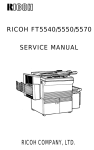
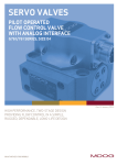
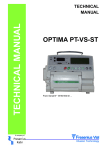
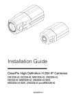
IP48 Win
Service Manual
(Control No. SM48W-001)
Table of Contents
1. Introduction ............................................................................ 1
Warning Items Concerning Maintenance and Repair ..........................................................1
Needed Tools ......................................................................................................................1
2. Description of Each Part ......................................................... 2
2-1
2-2
2-3
External Part Names ..................................................................................................2
Front Control Panel ....................................................................................................3
Internal Part Names ...................................................................................................4
Overall Configuration Diagram ...................................................................................5
3. Basic Specifications................................................................ 6
3-1
3-2
Table of Basic Specifications .....................................................................................6
Accessories list ...........................................................................................................7
4. Disassembly an Reassembly .................................................. 8
4-1
4-2
4-3
4-4
4-5
4-6
4-7
4-8
4-9
4-10
4-11
4-12
4-13
4-14
Cover Disassembly .....................................................................................................8
4-1-1 Detaching Cover: Right ..................................................................................8
4-1-2 Detaching the Control Panel Unit ...................................................................9
4-1-3 Detaching Cover Left: Lower ........................................................................ 10
4-1-4 Detaching Cover Front: Lower .....................................................................11
4-1-5 Detaching the Top Cover .............................................................................12
4-1-6 Detaching Cover Front: Upper .....................................................................13
Replacing the Thermal Head.................................................................................... 14
Replacing the Platen Roller ......................................................................................17
Replacing Printed Circuit Board: Main Control ........................................................18
Replacing the Power Transformer............................................................................20
Replacing Printed Circuit Board: Power Supply Unit (PSU) ....................................22
Replacing the Interlock Switch .................................................................................24
Replacing the Cover Open Switch ...........................................................................25
Replacing the Paper Sensor Unit .............................................................................26
Replacing the Ribbon End Sensor ...........................................................................27
Replacing the Printed Circuit Board: Panel .............................................................. 29
Replacing the Friction Gear Unit ..............................................................................30
Replacing the Idler Gear Unit ................................................................................... 31
Replacing the LF Motor ............................................................................................ 32
5. Test Print .............................................................................. 34
6. Changing Thermal Head Pressure ....................................... 35
i
7. Maintenance ......................................................................... 36
Cleaning the Inside ............................................................................................................36
7-1 Cleaning the Paper Guide ........................................................................................37
7-2 Cleaning the Platen Roller .......................................................................................37
7-3 Cleaning the Paper Sensor ......................................................................................37
7-4 Cleaning the Ribbon Peeling.................................................................................... 38
7-5 Cleaning the Ribbon Take Up Bar ...........................................................................38
7-6 Cleaning the Thermal Head .....................................................................................39
8. Troubleshooting.................................................................... 40
Cannot Print Well ...............................................................................................................40
9. Parts List .............................................................................. 41
10. Exploded Diagram ......................................................... 45 - 47
ii
1. Introduction
This manual gives detailed explanations of procedures for disassembling the parts of the IP48Win
Label Printer. Read this manual carefully before beginning service work.
Since the Service Manual includes important instructions for service work, keep it in a safe place.
This printer has been designed to be used with the supplies designated by Tohoku Ricoh. (refer to the
basic specifications). Since use of supplies other than those designated may cause problems such as bad
printed characters, bad label feeding, or damage to the head, be careful.
When ordering replacement parts, refer to the parts list at the back of this manual and the disassembly
diagrams, and make sure to write the part name and part number from that parts list on the order form,
together with the name of the printer model and its serial number.
This manual assumes a level of knowledge appropriate to a service person.
For explanations of unpacking procedures and installation locations for this product, refer to the
operator's manual included with it.
Warning Items Concerning Maintenance and Repair
Electric Shock Warning
Before disassembling this equipment, make sure to move the power switch to
OFF and to unplug the power cord.
With only the power switch in the OFF position, some areas remain electrified and
a danger of electric shock still exists.
Needed Tools
Philips screwdriver (magnetic tip)
Flat blade screwdriver (magnetic tip)
Philips screwdriver (magnetic tip)
Flat blade screwdriver (magnetic tip)
Hex wrench
Needle nose pliers
Tweezers
Cutters
2 × 9.84"
2 × 5.91"
1 × 2.95"
1 × 2.95"
0.06"
-1-
(250 mm)
(150 mm)
(75 mm)
(75 mm)
(1.5 mm)
2. Description of Each Part
2-1 External Part Names
Front Cover
Locking brackets for Transporting the Printer
(Will be taken off after opening the box)
Top Cover Handle
Front Control Panel
Power Switch
Paper Outlet Slot
(Output Slot Paper Guide)
Fig. 2-1 Front View / Side View
Back Panel DIP Switches (DIP SW)
SCSI interface
connectors
Fuse Holder
Power Connector
Fig. 2-2 Rear View
-2-
2-2 Front Control Panel
The control panel provides functions for producing labels (the label issuing mode functions) and for
changing various printer settings to suit different applications (the function setting mode).
For details refer to the operator's manual.
Error
Flashes when an error occurs.
Power
Indicates whether the printer's
power is on or off.
The lamp is lit when the power
is on.
Feed
Pause
Switches the printer between
the ready state and the pause
state. Each time this switch is
pressed, the Ready lamp turns
on or off.
Pressing this switch ejects
and cuts one page of labels.
Fig. 2-3 Front Control Panel
-3-
2-3 Internal Part Names
Interlock Switch
Platen Roller
Cover Switch
Paper Sensor
Paper Guide
Fig. 2-4 Lower Frame Inside
Thermal Head
Friction Gear
Ribbon End Sensor
Idler Gear Unit
Fig. 2-5 Upper Frame Inside
-4-
Overall Configuration Diagram
The printer is made up of five major parts: the upper assembly, the base assembly, electrical assembly,
front assembly, and cutter assembly. The mechanism and parts of each assembly is as follows.
Printer
1
2
Upper Assembly
Base Assembly
➀ Thermal Head
➁ Ribbon Feed Mechanism
➂ Ribbon Detection Mechanism
Ribbon End Sensor
➀ Power Supply Section
Power Supply
Fuse
➁ Paper Feed Mechanism
L/F Motor
Platen
Feed Roller
Paper Guide
➂ Paper Feed Detection Mechanism
Reflective Sensor
Interruptive-type center sensor
Interruptive-type form edge sensor
3 Electric Parts
Assembly
➀ Main Board
4 Front Assembly
➀ Front Control Panel
5 Cutter Assembly
(Cutter Machine)
➀ Cutter Mechanism
Cutter Carriage Motor
Rotary Knife
Fixed Knife
6 Others
➀ Cover Open Detection Sensor
Cover Open SW
Interlock SW
Control Circuit
➁ Service Meter
Upper ASSY
Thermal head
Ribbon feed mechanism
Ribbon detection mechanism
Front ASSY
Electrical Parts ASSY
Main board
Option Space
Front Control Panel
Base ASSY
Power supply section
Paper feed mechanism
Paper feed detect mechanism
Others
Cover open detect mechanism
-5-
3. Basic Specifications
3-1 Table of Basic Specifications
1.
2.
3.
4.
5.
6.
7.
8.
9.
Printing method:
Dot density:
Printing speed:
Maximum printing width:
Maximum printing length:
Page width:
Page length:
Page thickness:
Internal paper roll:
Thermal transfer method
400dpi (15.75 dots/mm)
0.5"/sec. to 4.0"/sec.(13mm/sec to 100mm/sec)
3.84" (97.54mm)
12.00" (304.8mm)
0.98" to 4.33" (25mm to 110mm)
0.19" to 12.00" (5mm to 304.8mm)
0.005" to 0.01" (0.12mm to 0.25mm)
(1) Winding direction
: Printing surface outside/inside
(2) Paper roll outer diameter
: ø7.08"(ø180mm) or less
(3) Paper tube inner diameter
: ø3.0"(ø76.2mm) (when using the ø3.93"and ø3.93"
diameter attachment
(ø100mm)
provided)
10. Fanfold forms:
page pitch
: 2.76"(70mm) or
Fanfold forms are placed
more
outside the printer. Print
quality is not guaranteed in
a 0.08"(2mm) region before
and after perforations.
11. Form sensor types:
(1) Interruptive-type form edge sensor (movable)
Detects notches in the forms
(2) Reflective sensor (movable)
Detects "eye" marks
(3) Interruptive-type center sensors (fixed)
Detects backing paper and
center hole. A blue backing
paper is recommended for
(1) and (3).
12. Ribbon width:
1.97" to 4.72" (50 to 120mm)
At least 0.39" (10mm)
wider than the forms.
13. Supply ribbon roll
(1) Winding direction:
Ink on the outside
(2) Paper tube inner diameter:
ø1.0" (ø25.4)
(3) Length of ending silver tape: 5.91" (150mm) or more
(4) Winding dimensions:
ø2.76" (ø70mm) diameter or less
(5) Ribbon length:
985ft (300m) : Reference value
14. Host interface:
SCSI conforming
15. Weight:
41.8 lbs (19kg)
16. Input power:
110, 120, 220, 230V AC,
50/60 Hz
available; specify when
ordering
17. Operating temperature
41 to 95°F (5 to 35°C),
and humidity requirements: 10 to 85% RH
18. Options
-1. External roll holder: Field option
Model number: RH-63
Roll diameter: No more than ø9.84" (ø250mm)
-2. Cutter:
Factory option
-6-
3-2 Accessories list
•
•
•
•
•
•
•
•
•
•
•
•
•
•
•
•
Ribbon roller gear unit (2)
Ribbon core (1)
Roll holder plate (2)
3.94" (100mm)-inner diameter paper tube attachment set (1)
Roll holder shaft (1)
Power Cable (1)
Spare fuse (1)
Screwdriver (1)
Unpacking Instructions
Screw Lock (2)
SCSI Terminator (1)
Printer driver floppy disk (1)
Output paper guide (1)
SCSI interface cable (1)
Operation Manual (1)
Setup Guide (1)
-7-
4. Disassembly an Reassembly
4-1 Cover Disassembly
4-1-1 Detaching Cover Right
Electric Shock Warning
Before disassembling this equipment, make sure to move the power switch to
OFF and to unplug the power cord.
With only the power switch in the OFF position, some areas remain electrified and
a danger of electric shock still exists.
1. Switch the power switch to the OFF position, then unplug the power cable from the electrical outlet.
2. Remove the two exterior screws holding cover: right in place.
Fig. 4-1
Screws
3. Open the top cover.
Open and close the top cover whenever necessary for the job at hand.
4. Remove the two fixing screws on the inside of cover: right and the fixing screw for handle: cover.
5. Remove handle: cover, and remove the cover: right by sliding it upward.
Screws
Fig. 4-2
-8-
4-1-2 Detaching the Control Panel Unit
1. Remove the three fixing screws for the control panel unit.
Screws
Screw
Fig. 4-3
2. Disconnect the connectors at the two places on the side of the control panel.
-9-
4-1-3 Detaching Cover Left: Lower
1. Remove the four fixing screws for cover left: lower and the two fixing screws for hinge: assembly.
Detach cover left: lower.
Hinge
Screws
Screws
Fig. 4-4
Electric Shock Warning
Before disassembling this equipment, make sure to move the power switch to
OFF and to unplug the power cord.
With only the power switch in the OFF position, some areas remain electrified and
a danger of electric shock still exists.
- 10 -
4-1-4 Detaching Cover Front: Lower
1. Remove the two right side fixing screws for cover front: lower.
2. Remove the two left side fixing screws for cover front: lower .
Screws
Fig. 4-5
Screws
Fig. 4-6
- 11 -
4-1-5 Detaching the Top Cover
1. Remove the six fixing screws for the upper cover (four on the top, and two on the side).
Screws
Screws
Screws
Fig. 4-7
Fig. 4-8
- 12 -
4-1-6 Detaching Cover Front: Upper
1. Remove the four fixing screws for the front of the cover. Remove the fixing screw for the chain.
Screws
Screws
Chain Fixing Screw
Fig. 4-9
- 13 -
4-2 Replacing the Thermal Head
The thermal head of this printer was designed for durability, but when it is used for a long time, broken
lines (white spaces with missing dots) will occur.
In order to maintain print quality, it is necessary to change the head sometimes. The procedures for
changing it are shown below. (The thermal head is a consumable part).
1. Switch the power switch to OFF. Open the top cover and remove the ribbon at the roll-in receiving
side. Then, open the thermal head cover by rotating it towards the back of the printer.
Caution
Note that the thermal head may be hot, even if the power is off.
Thermal Head Cover
Fig. 4-10
2 Push the right and left release levers and remove the head by pushing it up from below.
Release Levers
Fig. 4-11
- 14 -
3 Disconnect the two connectors on the thermal head unit.
Caution
Grasp the connector part to remove the head. Pulling and holding the head by the harness
may cause a bad connection.
Thermal Head
Connectors
Fig. 4-12
4. Being very careful not to scratch the new thermal head, connect the cables and lock them into place.
Set the new thermal head unit into the guide holes in the thermal head brackets. Fix the thermal head
into place by pressing the left and right release levers.
At this time, be careful not to bend the ribbon peeling (by not pushing it).
New Thermal Head
Fig. 4-13
- 15 -
Caution
When connecting or disconnecting connectors, do it only after verifying the orientation and
position. Take care to avoid bending the pins of the connectors.
5. Close the thermal head cover.
Reinstall the ribbon and labels, then close the printer cover.
Caution
When replacing the thermal head unit, be very careful to avoid scratching or staining the new
thermal head unit. After replacing, quickly wipe off the new unit.
- 16 -
4-3 Replacing the Platen Roller
The platen roller will wear out after the printer has been used for an extended period of time, resulting
in fading of print or other print quality problems. When this occurs, the platen roller must be replaced as
follows.
1. Move the cutter carriage to the left.
2. Flop open the release levers at the ends of the platen roller and remove the platen roller from the
printer.
Release Levers
Platen Roller
Fig. 4-14
- 17 -
4-4 Replacing Printed Circuit Board: Main Control
1. Do "Cover Disassembly" procedures 4-1-1 ~ 4-1-2.
2. Remove the five fixing screws.
Screws
Screws
Fig. 4-15
3. Disconnect all the connectors attached to the main circuit board.
CN11
CN10
CN9
CN7
CN8
CN5
CN6
CN3
CN4
CN2
CN1
Fig. 4-16
- 18 -
4. Install the new board by reversing the removal procedures.
5. Before attaching the covers, do the procedures below.
① Set the DIP switches on the rear face to the same settings as those for the old main control board.
② If you are using the serial interface, try connecting the cable connection. If the screws cannot be
tightened well, there is a possibility that the screw lock type isn't suitable. Change it for the screw
lock on the old main control board or a screw lock that was packaged with the printer.
Note
After connecting the connector, check to see if it is really connected or not.
- 19 -
4.5 Replacing the Power Transformer
1. Do "Cover Disassembly" procedures 4-1-1 ~ 4-1-4.
2. Remove the fixing screw for the earth line.
Screw
Fig. 4-17
3. Disconnect the two connectors coming out of the power transformer.
Connectors
fig. 4-18
- 20 -
4. Remove the four power transformer fixing screws at the bottom of the printer.
Screws
Fig. 4-19
5. Take the power transformer out of the printer.
Power Transformer
Fig. 4-20
6. Install the new transformer by reversing the removal procedures.
- 21 -
4-6 Replacing Printed Circuit Board: Power Supply Unit (PSU)
1. Do "Cover Disassembly" procedures 4-1-1 ~ 4-1-4
2. Open the top cover and remove the two fixing screws for the cover: drive section: lower.
Screws
Fig. 4-21
3. Remove the five fixing screws for the printed circuit board: main control, and disconnect connectors
CN8 and CN 11.
CN11
CN8
Fig. 4-22
4. Disconnect the cable connector from the power transformer.
- 22 -
5. Disconnect the interlock switch connector.
Interlock Switch Connector
Fig. 4-23
6. Remove the three fixing screws for printed circuit board: PSU and take the board out of the printer.
Screws
Fig. 4-24
7. Install the new board by reversing the installation procedures (Use new cable bands to replace those
that were cut.)
- 23 -
4-7 Replacing the Interlock Switch
1. Do "Cover Disassembly" procedures 4-1-1 ~ 4-1-2.
2. Disconnect the interlock switch connector.
Connectors
Fig. 4-25
3. Remove the two fixing screws for the interlock switch.
Screws
Fig. 4-26
4. Install the new interlock switch by reversing the removal procedures.
- 24 -
4-8 Replacing the Cover Open Switch
1. Do "Cover Disassembly" procedures 4-1-1 ~ 4-1-2.
2. Remove the five fixing screws for the printed circuit board: main control and disconnect CN2.
CN2
Fig. 4-27
3. Remove the two fixing screws for the cover open switch.
Caution
The screw on the left is tightened with reinforcing hex nut in the rear. Be careful not to drop or
lose it.
4. Cut the binders and remove the cover open switch.
Screws
Cover Open Switch
Fig. 4-28
5. Install the new interlock switch by reversing the installation procedures (Use new cable bands to
replace those that were cut.)
- 25 -
4-9 Replacing the Paper Sensor Unit
1. Remove the two fixing screws for the base: paper sensor unit.
Screws
Fig. 4-29
2. Disconnect connector CN1.
CN1
Fig. 4-30
3. Install the sensor by reversing the removal procedures
- 26 -
4-10 Replacing the Ribbon End Sensor
1. Open the top cover of the printer
2. Remove the ribbon at the roll-in receiving side, and place it in the V groove.
3. Remove the fixing screws for the bracket: end ribbon sensor.
Screw
Fig. 4-31
4. Remove the connector for the ribbon end sensor.
Sensor
Fig. 4-32
- 27 -
5. While pressing the claw on the end ribbon sensor towards the interior, pull it upward, extracting it
from the bracket.
Fig. 4-33
6. Install the new sensor by reversing the removal procedure.
- 28 -
4-11 Replacing the Printed Circuit Board: Panel
1. Do "Cover Disassembly" procedures 4-1-1 ~ 4-1-2.
2. Remove the four fixing screws for printed circuit board: panel and remove the board.
Screws
Printed Circuit Board: Panel
Fig. 4-34
3. Install the new board by reversing the removal procedures.
Caution
Since the screws are self-tapping, be careful not to overtighten them.
- 29 -
4-12 Replacing the Friction Gear Unit
1. Open the top cover of the printer
2. Take off the E-ring that holds the friction gear unit in place, then remove the friction gear.
E-ring
Fig. 4-35
3. Install the new gear by reversing the removal procedures.
- 30 -
4-13 Replacing the Idler Gear Unit
1. Open the top cover of the printer.
2. Loosen the two hex type set screws for knob: roll-in receiver, then remove the knob.
Hex Type Set Screws
Idler Gear Unit
Fig. 4-36
3. Detach the crescent shape snap ring holding the idler gear unit in place, then take out the idler gear
unit.
Crescent shape snap ring
Fig. 4-37
4. Install the new gear by reversing the removal procedures
- 31 -
4-14 Replacing the LF Motor
1. Do "Cover Disassembly" procedures 4-1-1 ~ 4-1-2.
2. Remove the printed circuit board: main control.
3. Remove the two fixing screws for the base: paper sensor and disconnect connector CN1, then remove the paper sensor unit.
Screws
Screws
Fig. 4-38
4. Remove the E-ring holding the idler gear: LF in place.
E-Ring
Fig. 4-39
- 32 -
5. Remove the three fixing screws for the LF motor.
Cutting the cable bands, take out the LF motor.
Screws
LF Motor
Fig. 4-40
6. Install the new LF motor by reversing the removal procedures.
- 33 -
5. Test Print
The following method can be used to make a test print. Be sure to make one test print during the
installation procedure before connecting the printer to a computer or terminal.
● Make sure that the paper type function is set to continuous forms mode. (DIP SW6 on the back panel
should be set to ON.)
● Load 3.94" (100mm) continuous paper (either regular paper or coated paper) and 4.72" (120mm)wide ribbon (wax/resin type) into the printer.
● To start the test print, turn the power switch to ON while pushing the Feed button on the front control
panel.
● Continue pushing the Feed button on the panel until the Error LED lights.
● To stop the test, turn the power switch to OFF after pushing the Pause switch.
Test Print Examples
● At first the test print checks whether there is any abnormality in the thermal head. On the first page,
there are 10 and 5mil patterns, and after that, a demo print pattern is printed on the second page.
10mil Pattern
Test Print Example
- 34 -
6. Changing Thermal Head Pressure
① When the label width is less than 2" (50mm), while pressing the sides of the thermal head's heat
element, move the pressure change plate until it is caught under the two disks.
Thermal Head Pressure Change Plate
Fig. 6-1
② When the label width is 2" (50mm) or more, while pressing the sides of the thermal head's heat
element, remove the pressure change plate under the two disks.
- 35 -
7. Maintenance
Follow this maintenance schedule in order to achieve the maximum possible life from the printer.
Failure to follow this maintenance schedule may void the warranty.
Warning
● All maintenance should be performed with the printer disconnected from the
power source, with the power switch in the OFF position.
● Isopropyl alcohol, and methanol are flammable. Exercise extreme caution
when dealing with them.
● Don't clean the thermal head when it is hot.
Caution
① The suggested solvents for cleaning the thermal head, platen, feed roller and label
sensor are isopropyl alcohol or methanol. The use of solvents other than isopropyl
alcohol or methanol for cleaning is likely to result in damage to the parts.
② When cleaning the printer, use a clean and untreated cloth.
Be sure not to use a chemical dustcloth.
③ Whenever working inside the printer, remove all jewelry and gloves. Also be careful not
④
⑤
to scratch the thermal head with metal buttons, rings, bracelets, or any other metal
objects.
Never lubricate any part of the printer. All parts are factory lubricated, and it is not
necessary to lubricate again when using the printer.
At no time should any solvent, cleaning solution, or anything else be sprayed onto, into,
or around the printer. If spray gets in the printer, damage may result.
Cleaning the Inside
Turn off the power switch, unplug the power cable and open the printer's top cover. Remove the label
and ribbon and clean the parts indicated in figures 7-1 to 7-6 using a clean, untreated cloth dampened
with isopropyl alcohol or methanol.
- 36 -
7-1 Cleaning the Paper Guide
Clean the entire area while spreading and bringing together the paper guides.
Fig. 7.1
7-2 Cleaning the Platen Roller
Wipe the platen roller while turning the gear by hand.
Fig. 7-2
7-3 Cleaning the Paper Sensor
Moisten a cloth with alcohol and feed it through the sensor in the same manner as with labels, then
move the cloth back and forth a few times to clean the sensor.
Fig. 7-3
- 37 -
7-4 Cleaning the Ribbon Peeling
Caution
Do not push strongly against the ribbon peeler part.
Fig. 7-4
7-5 Cleaning the Ribbon Take Up Bar
Fig. 7-5
- 38 -
7-6 Cleaning the Thermal Head
Caution
Note that the thermal head may be hot, even if the power is off.
Fig. 7-6
- 39 -
8. Troubleshooting
This section describes check points and procedures to follow if you experience trouble with the printer.
Cannot Print Well
Printer Condition
Possible Causes
Remedy
Cannot test print.
· Not pressing paper Feed switch.
· Turn power on while pressing
Feed switch.
Doesn't print.
· Ribbon installed with back side
out or there is no ribbon.
· Printer has no power.
· Install the ribbon with the ink side
(face) outward.
· Check power cable, turn on power
switch.
· Replace communication cable.
· Communication cable bad, or the
line has become severed.
· The type of supplies or density selected is not suitable.
· Now in print pause state.
· Supply materials have changed.
Print quality is bad or · Supplies other than those designated are being used.
ribbon has problems.
· Platen roller is worn.
· Thermal head is too old head.
· Ribbon is wrinkled.
· The ribbon is installed at an angle.
· The type of supplies or density selected is not suitable.
· The paper guide has been set incorrectly.
- 40 -
· Select suitable values for supplies
and density.
· Press the Pause until the Error
LED is extinguished.
· Raise the print density.
· Change to designated Supplies.
· Replace platen roller.
· Replace the thermal.
· Install the ribbon so that no
wrinkles appear.
· Install the ribbon correctly.
· Select suitable values for supplies
and density.
· Set the paper guide correctly for
the paper, with no gap between
paper guide and paper.
9. Parts List
Ref. No.
1
2
3
4
5
6
7
8
9
10
11
12
14
15
16
17
18
19
20
21
22
23
24
25
26
27
28
29
30
31
32
33
34
35
37
38
39
40
41
44
45
46
Part No.
7C36-0524
7C35-1341
7C36-0485
7C38-0342
7C36-2757
7C37-0270
1204-2188
7C35-0171
7C36-0483
1403-0736
7C36-1025
7C42-0380
7C37-0555
7C35-0106
7C38-0250
7C36-0280
7C38-1356
7C38-1374
7C38-1380
7C35-1335
7C37-1372
7C37-1371
7C37-1334
7C35-1352
7C31-1316
7C37-1333
7C36-0562
7C37-1073
7C35-5261
7C35-1332
7C35-1105
7C40-1411
7C35-1325
7C35-1340
7C35-1000
7C35-1070
7C31-1060
7C31-1054
C203-3027
7C35-1104
7C36-1113
7C35-3301
No. of items
1
1
1
1
1
1
1
1
1
1
3
1
1
1
1
1
1
1
1
1
1
1
1
1
1
1
2
1
2
4
1
2
2
1
1
1
2
2
2
1
5
1
Name
Thermal head: assembly
Cover: Top
Platen: assembly
Printed circuit board: main control: assembly
Electric transformer
Printed circuit board: PSU: assembly
Interlock SW: DDIL-AILA
Cover open switch: assembly
Shaft: roll holder: assembly
Reflective type photo sensor: GP2S30
Bearing shaft: guide shaft: ribbon: roll-in
Printed circuit board: panel: assembly
Gear: friction: roll-in: assembly
Sleeve: gear: idler: assembly
L/F motor: assembly
Printed circuit board: noise filter: assembly
Cover: right
Cover: front: right: assembly
Decal: control panel
Cover: left: lower
Cover: front: lower
Cover: front: upper
Cover: rear: bottom: left
Handle: cover: right
Handle: side cover: left: upper
Cover: rear: upper
Ribbon roller: assembly
Cover: drive section: upper
De-electrifier brush
Bracket: Cover: front: lower
Pressure plate: interlock SW
Fixing board
Bracket: cover: front: right
Hinge: assembly
Base:
Side plate: latch
Set: shaft ASSY
Eccentric: Set lever
Stepped screw: stopper
Bracket: interlock SW
Stud: control board
FG mesh
- 41 -
Ref. No.
47
48
47
50
51
52
53
54
55
56
57
58
59
60
61
62
63
64
65
66
67
68
69
70
71
72
73
74
75
76
77
78
79
80
81
82
83
84
85
86
87
88
Part No.
7C31-1059
7C31-1058
7C31-1055
7C31-1067
7C31-1057
7C35-5602
7C31-1033
7C35-1022
7C35-0121
7C35-0120
7C36-1026
7C31-1081
7C35-5506
7C31-5647
7C31-5648
0807-4076
7C31-5646
7C31-5645
7C31-5649
7C31-4722
7C31-5540
7C31-5541
0807-5037
7C31-5546
7C31-5549
7C31-5547
7C36-5509
7C31-5551
0725-0160E
7C40-4701
7C36-5508
7C36-5507
7C40-1410
7C31-5590
7C31-5591
7C31-5592
7C35-1314
7C35-1313
7C36-5263
7C31-5585
7C35-5262
5447-2769
No. of items
1
1
2
1
1
6
2
3
1
1
1
2
1
1
1
1
2
1
1
2
1
3
1
1
2
2
1
1
1
2
1
1
2
2
1
1
2
1
1
3
1
2
Name
Knob: set lever
Set lever: frame
Bracket: set lever
Spring: set lever: back
Shaft: set lever
Catcher: ribbon
Positioning pin: upper
Stay: upper
Side plate: upper: right: Calking
Side plate: upper: left: Calking
Guide shaft: ribbon: take up
Reinforcement plate: upper frame
Blade spring: ribbon return preventer
Knob: ribbon roll-in
Crescent snap ring
Washer: 8.2 × 6.1 × 0.3
Compression spring: idler
Friction pad: idler
Tape: fixing: friction pad
Gear: idler: roll-in: II
Shaft: gear: friction
Corrugatedwasher: 8
Washer: 8.1: t1
Gear: friction, movable
Friction pad: roll-in
Spacer: friction
Compression spring: gear
Adjuster: friction: roll-in
C shape 16 snap ring for shaft
Gear: platen
Collar: guidance: torsion
Torsion coil spring: ribbon: roll-in
Magnet catch: assembly
Expansion spring: lever
Lever: thermal head: left
Lever: thermal head: right
Hinge: cover: front: upper
Chain
Cover thermal head: harness
Expansion spring: cover
Step screw: M3
Step screw: Φ4 × M3
- 42 -
Ref. No.
89
90
91
92
93
94
95
96
97
98
99
100
101
102
103
104
105
106
107
108
109
110
111
112
113
114
115
116
117
118
119
l20
121
123
124
125
126
127
128
129
130
131
Part No.
7C35-1110
5505-2752
0807-3055
1106-0266
1106-2979
7C36-1019
7C35-1013
7C35-0110
7C36-0118
7C36-1214
7C35-4720
7C35-4721
7C31-4721
7C35-1071
7C31-5127
7C35-1112
1204-2158
7C35-1106
7C35-1040
7C35-1041
7C35-1042
7C35-1044
7C35-1045
1105-0322
7C35-1046
7C35-1043
7C31-1048
7C31-1085
7C31-1047
7C31-1049
7C31-1086
7C35-1018
7C38-0108
7C38-0481
7C35-1353
7C31-1327
7C31-1051
1150-0352
7C38-0315
7C37-1335
7C37-5836
7C31-1324
No. of items
1
4
6
1
1
2
1
1
1
1
1
1
1
1
2
1
1
2
2
2
1
2
4
2
2
1
4
2
4
1
1
1
1
2
2
1
2
1
1
1
1
1
Name
Bracket: ribbon end sensor
Stay: printed circuit board
Washer: 7 × 4 × 1
Snap bushing: Φ23.8
Bushing: short
Bracket: base: paper guide
Bottom plate: roll paper
Side plate: lower: left: Calking
Side plate: lower: right: Calking
Stay: lower
Lever: platen: left
Lever: platen: right
Idler gear: LF
Strut: side plate: latch
Nut: T type: M4
Bracket: power SW
Rocker SW
Shield: electric cable
Hinge: lower
Hinge: upper
Shaft: hinge: front
Torsion spring: hinge
Guide collar: torsion spring
Edge saddle: EDS2
Shaft: spring: cap
Shaft: hinge: back
Friction pad: hinge
Pressure plate: friction: hinge
Disc spring: hinge
Hex nut: M10 × 1
Pin: pressure: fixing
Fixing plate: reflection sensor
Paper sensor ASSY
Cap plate: roll paper: assembly
Bracket: cover: right
Pre-coat screw
Nut: T-type: M3
AC cable
Harness: thermal head
Cover: back: lower: right
Cover: transformer
Blank plate: side cover: right
- 43 -
Ref. No.
S1
S2
S3
S4
S5
S6
S7
S8
S9
S10
S11
S12
S13
S14
S15
S16
S17
Part No.
7C35-1360
7C31-8551
0951-3004B
0951-3006B
0951-3008B
0951-4006B
0353-0060B
0352-5060B
0354-0060B
0323-0060B
0413-0082B
0413-0062B
0313-0140B
0951-4010B
0710-0040B
0710-0020B
0553-0040E
No. of items
14
4
42
51
8
50
13
8
14
2
12
6
2
7
1
1
5
E1
E2
E3
0720-0040E
0720-0060E
0720-0100E
9
13
5
Name
Finished screw: M3 × 6
Finished screw: jacketed
Flat smooth screw: M3 × 4
Flat smooth screw: M3 × 6
Flat smooth screw: M3 × 8
Flat smooth screw: M4 × 6
Small binding screw: M3 × 6
Small binding screw: M2.5 × 6
Small binding screw: M4 × 6
Flat countersunk head screw: M3 × 6
Self-tapping screw: M3 × 8
Self-tapping screw: M3 × 6
Small pan head screw: M3 × 140
Flat smooth screw: M4 × 10
Hex nut: M4
Hex nut: M2
Hex hole set screws: M3 × 4
E-ring: 4
E-ring: 6
E-ring: 10
- 44 -
10. Exploded Diagram
10-1 Main Unit
- 45 -
10-2 Lower Frame
- 46 -
10-3 Upper Frame
- 47 -