1
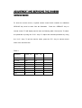
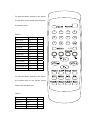
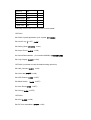
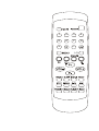
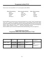
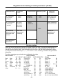
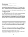
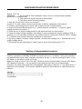
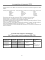
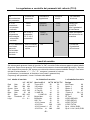
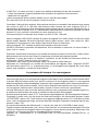
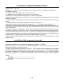
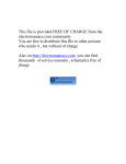
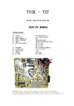
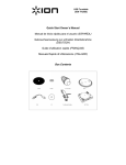
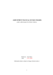
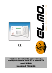
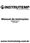
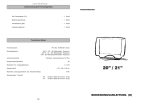
TV2K - TXT
COLOUR TELEVISION RECEIVER
SERVICE MANUAL
SECIFICATION
z
SYSTEM
z
POWER INPUT
z
POWER CONSUMPTION
z
AERIAL IMPEDANCE
z
TUNER
z
RECEIVING CHANNELS
PAL/SECAM,B/G,DK, I.
AC 170-245V(50/60Hz)
60W
75OHM UNVALANCED
VOLTAGE SYNTHESIZER TUNING
VHF-L E2-S6
VHF-H S7-S41
UHF E21-E69
z
PROGRAMME
z
PICTURE TUBE
z
SOUND OUTPUT
z
SPEAKER
z
AV JACKS
MAX.99 PROGRAM MEMORIES
14”,20”,21”;90°
2.0W
3W 8 OHM
FULL SCART ×1
CAUTION: Before servicing the chassis, read the “Safely Precaution”.
“X -Ray radiation Precaution” and “Product Safety Notice” in this manual.
X-RAY RADIATION PRECAUTION
1. Excessive high voltage can produce potentially hazardous X-RAY RADIATION. To
Avoid such hazards the high voltage must be specified limit. The normal value of the
high voltage of this receiver is 24.5KV +/-2KV under 230V AC power source. The
high voltage must not exceed 27KV.
2. Each time a receiver requires servicing the high voltage should be checked following
the HIGH VOLTAGE CHECK procedure in this manual. It is recommended the
reading of the high voltage be recorded as a part of the service record. It is
important to use an accurate and reliable high voltage meter.
3. The primary source of X -RAY RADIATION in this TV receiver is the picture tube.
For continued X-RAY RADIATION protection, the replacement tube must be exactly
the same type tube as used in this TV receiver.
4. Some parts in this receiver have special safety-related characteristics for X-RAY
RADIATION protection. For continued safety, parts replacement should be
undertaken only after referring the PRODUCT SAFETY NOTICE below.
SAFETY PRECAUTION
WARNING: Service should not be attempted by anyone unfamiliar with the necessary
Precautions on this receiver.
The following are the necessary precautions to be observed before servicing this
chassis.
1.
Since the power supply circuit of this receiver is directly connected to the AC
power line. An isolation transformer should be used during any dynamic service to
avoid possible shock hazard.
2.
Always discharge the picture tube anode to the CRT conductive coating before
handling the picture tube. The picture tube is highly evacuated and if broken, glass
fragments will be violently expelled. Use shatterproof goggles and keep picture tube
away from the unprotected body while handling.
3.
When replacing a chassis in the cabinet, always be certain that all the protective
devices are put back in place, such as: nonmetallic control; knobs, insulating covers,
shields, isolation resistor-capacitor, network, etc.
4.
When replacing parts or circuit boards, disconnect the power cord.
5.
When replacing a high voltage resistor (metal oxide resistor) on circuit hoard,
keep the resistor APP. 10mm(1/2 in.) away from circuit board.
6.
Connection wires must be kept away from components with high voltage or high
temperature.
7.
If any fuse in this TV receiver is blown, replace it with the FUSE specified in the
chassis parts list.
8.
The receiver is designed to operate with 230V(50Hz) AC mains.
PRODUCT SAFERY NOTICE
Many electrical and mechanical parts in this chassis have special safety-related
characteristics are often passed unnoticed by a visual inspection and the X-RAY
RADIATON protection afforded by them cannot necessarily be obtained by using
replacement components rated for higher voltage. The use of substitute replacement
parts that do not have the same safety characteristics as specified in the parts list may
create shock, fire, X-RAY RADIATION or other hazards.
GENERAL ADJUSTMENT
AUTOMATIC DEGAUSSING
An automatic degaussing coil is attached around the picture tube, degaussing the tube
properly in about one second after the set is switched on. If the receiver is moved or
faced on a different direction, the power must be switched off at least 15 minutes in
order that the automatic degaussing circuit operated properly. External degaussing is
necessary if the automatic degassing proves ineffective after the set is moved.
B+ ADJUSTMENT
CAUTION: To avoid X-ray hazards and result in a nominal display width, B+ voltage
must be set in the scale of 108.0V+/-0.5V.
1.
Make sure the AC power supply is 230V, 50Hz.
2.
Switch on the TV receiver, tune in an active channel.
3.
Measure the voltage between C641 on Main P.C. Board by DC voltmeter.
4.
Set contrast, brightness, color to maximum.
5.
Adjust VR631 on Main P. C. Board for B+108.0V+/-0.5V voltage reading.
HIGH VOLTAGE CHECK
CAUTION: There is no high voltage adjustment in this chassis, B+108V voltage
directly relates to the high voltage. The high voltage does not exceed 27KV under any
conditions.
1.
Connect an accurate high voltage meter to the second anode cap of the picture
tube.
2.
Turn on the receiver, set brightness and contrast to minimum (Zero beam
current).
3.
Make sure the high voltage does not exceed 27KV.
4.
NO matter whether the luminance, contrast and chrominance controls are set to
maximum or minimum, the high voltage must be kept under 27KV.
FOCUSING
Receive a TV test pattern signal; adjust controls for optimum picture. Adjust Focus
Control for a well-defined, sharpest display in the center area of the screen.
ADJUSTMENT AND SERVICING THE CHASSIS
SERVICE MODE
To enter the service mode, a special remote control which contains an additional
SERVICE key must be used. See the illustration.
Press the ‘SERVICE’ key on
remote control, TV will display service menu as following table 1 line by line. To select
the parameter by using the ‘P+/P-’ keys. To adjust the selected parameter by using
the ‘V+/V-’ keys. To quit the service mode, press the ‘P.P.’ key on remote control
when in the service mode.
Table 1
Parameter
Value 14 “
Red Gain
DC Red
Green Gain
DC Green
Blue Gain
DC Blue
Apr Threshold
Logo
32
063
32
063
32
063
12
6------------
Value 20”,
21 “
40
063
40
063
40
063
12
6------------
To enter the table 2, press the ‘OK’ key for
the first time on the remote control when in
the service mode.
1
2
3
4
5
6
7
8
Table 2
Parameter
Tuner AGC
H position
VPOS 50
VPOS 60
VAMP 50
VAMP 60
Bright max
Bright min
Sub Tint
VCO Coarse
VCO Fine
VCO Coarse L1
VCO Fine L1
Value
22
32
10
10
47
53
63
00
32
05
063
05
080
To enter the table 3, press the ‘OK’ key for
the second time on the remote control
when in the service mode.
Table 3
Parameter
AGC gain
Option 1
Option 2
Option 3
Value
00
48
00
06
9
-/-Ⅰ /Ⅱ
Option 4
Option 5
ST Ttext
H POS OSD
V POS OSD
H POS TXT
V POS TXT
09
00
00
001
01
066
04
Following are the items of the OPTIONS in more details.
OPTION1:
B5=P/N/S Crystals application (0=2 crystals, 1=1 crystal)
B4=Cutoff Loop (0= OFF, 1=ON)
B3=Safety_Reset (0=Active, 1=non)
B2=Super Tuner (0=OFF, 1=ON)
B1=Sound Demodulation
(0= Intercarrier/MONO, 1=QSS/NICAM)
B0=Logo Display (0=OFF, 1=ON)
OPTION2: (It’s better to keep the default setting option2=0)
B5=Half_Contrast (0=OFF, 1=ON)
B4=Color 6db (0=OFF, 1=ON)
B3=APR Feature (0=ON, 1=OFF)
B2=Black Stretch
(0=ON, 1=OFF)
B1=Auto Flesh (0=ON, 1=OFF)
B0=Coring (0=ON, 1=OFF)
OPTION3:
B5=AVL (0=OFF, 1=ON)
B4=PIF Over modulation (0=OFF, 1=ON)
B3=Market_France-SECAM L/L’
(0=OFF, 1=ON)
B2=Manual/Auto Cutoff (0=Manual, 1=Auto Cutoff)
B1=Mute pin Low/High To control the speaker (0=Low, 1=High)
B0=TDA7449/TDA7439 (0=TDA7449, 1=TDA7439)
OPTION4:
B4=SCART2 (0=OFF, 1=ON)
B3=RGB (0=OFF, 1=ON)
B2=SVHS (0=OFF, 1=ON)
B1=AV2 (0=OFF, 1=ON)
B0=AV1 (0=OFF, 1=ON)
OPTION5 and ST Ttext is for teletext setting only. It normally could not be changed. If
it’s necessary to adjust the OPTION 5, please read the following information before
adjustment.
A. For CPUs with English, French, German, Polish or English, French, German, Turkish,
Please refer to the setting as below.
1. If OPTION 5 = 00, then the TEXT languages like "ENGLISH, FRENCH, SWEDISH,
TURKISH, GERMAN, PORTUGUESE, ITALIAN, RUMANIAN " can be decoded.
2. If OPTION 5 = 02, then the TEXT languages like "POLISH, FRENCH, ESTONIAN,
CZECH, GERMAN, SERBIAN, LETTISH, RUMANIAN " can be decoded.
3. If OPTION 5 = 04, then the TEXT languages like "ENGLISH, FRENCH, SWEDISH,
CZECH, GERMAN, PORTUGUESE, LETTISH, RUMANIAN " can be decoded.
4. If OPTION 5 = 06, then the TEXT languages ENGLISH, FRENCH, SWEDISH, TURKISH,
GERMAN, PORTUGUESE, LETTISH, RUMANIAN can be decoded.
B. For coming new OTP/CPU with English, Russian, Czech, Polish, the setting of the OPTION
5 will be changed as below.
1. If OPTION 5 = 00, then the TEXT languages like "ENGLISH, FRENCH, SWEDISH,
CZECH, GERMAN, PORTUGUESE, ITALIAN, RUMANIAN " can be decoded.
2. If OPTION 5 = 02, then the TEXT languages like "ENGLISH, RUSSIAN, SWEDISH,
TURKISH, GERMAN, PORTUGUESE, ITALIAN, RUMANIAN " can be decoded.
3. If OPTION 5 = 04, then the TEXT languages like "POLISH, RUSSIAN, SWEDISH,
CZECH, GERMAN, SERBIAN, ITALIAN, RUMANIAN " can be decoded.
4. If OPTION 5 = 06, then the TEXT languages like "POLISH, RUSSIAN, SWEDISH,
CZECH, GERMAN, PORTUGUESE, ITALIAN, RUMANIAN can be decoded.
Normally, it is supposed not to set OPTION 5 = 01. If you set the OPTION 5 = 01, then the font
can be switched by press key MENU on remote control in TEXT mode for TV3K. If you set
OPTION 5 = 00, 02, 04, 06, then there is no any activity while press MENU in TEXT mode.
Please check.
A.F.C. ADJUSTMENT
Removing any R.F. signal source and prevent any stray signal source from entering
the tuner by shorting the tuner input inner contact to the out screen.
Inject the 38.9 MHZ carrier into the tuner IF output pin (pin 11).Select the parameter
‘VCO Coarse’ in the service mode (see Table 2).The ‘VCO Status…’will appear on
the screen. Then press the ‘AV’ key on remote control, the CPU will adjust
automatically until the ‘VCO Status OK’ appears on the screen. If this can not be
achieved, i.e. there is no any pattern on the screen, please adjust the T201 first until a
stable pattern appears on the screen. And then press the ‘AV’ key on remote control.
The CPU will adjust automatically once again until the ‘VCO Status OK’ appears on
the screen.
GEOMETRY
To adjust the picture position and vertical size, select the appropriate parameter in the service
mode and adjust as necessary. Please see table 2.
Remote control
29
DIRECTIVTY
6m(MIN)
8m(NOR
OK
)
30
DIRECTIVTY
30°FROM LIGHT AXIS
5m(MIN)
7m(NOR
OK
)
1
2
3
4
5
6
7
8
9
-/-Ⅰ /Ⅱ
USER MANUAL
Programmes’ setting TV-2K
Press remote control key MENU. On TV screen appears tables MENU:
After first pressing
Picture
Brightness
Contrast
Colour
Sharpness
After second pressing
Install
Auto Tune
Manual Tune
Fine Tune
Store
After third pressing
Setup
Timer
Organize
Function
Language
Press the MENU key on remote control 2 times and choose function “Install”. Press P- key and choose
“Auto Tune” or “Manual Tune” functions. Press the OK key to enter programs’ search mode. When
programme appears, press the MENU key and return to the installation table. Pres the P- key and choose
function “Store”. Press the OK key. When installation table appears, choose required programme
number in table “Programe” by using “+”, “-” keys, then choose Store and OK.
Press the MENU key to return to the installation table and start setting of the next programme.
Control of supply voltages
Programme UEBL (PAL) must by turned on TV set
Parameter name
Parameter
value
Control element
Measuring place
Supply voltage
(106-114)V
VR5O1
D6O7"+”
6,O-6,6V
VR5O1
Stand connector
Measuring
conditions
UEBL
Filament voltage
-3-
BRIGHT.SATURAT -31
CONTRAST -45
Regulation and checking of raster parameters’ (TV-2K)
Parameter name
4.1 Centering
-horizontal
-vertical
4.2 Picture size
-horizontal
-vertical
Parameter
value
Control element
+6 mm
+4 mm
Hposition
VPOS 5O
22.5-24.5
windows’
16.5-18.0
windows
Measuring place
O-63
O-15
Measuring
conditions
UEBL PAL GRID
at 9 gradations
of brightness
UEBL brightness
from min. to max.
VR5O1
VAMP 5O
O-63
4.3 Nonlinear
distortions along
horizontal and
vertical
See user
parameters’
checking
4.4 Geometrical
distortions
GRIG at 9
gradations of
brightness
AS
Service modes
Press the service key and the OK key on remote control one time. First service table appears on
the screen. You will have second service table Service V3.0 - after pressing the OK key the
second time and Design table - after pressing one more time. Set the raster parameters visually
by using the remote control keys “+”, “-”, “P+” and “P-”: size, centering, nonlinear and geometrical
distortions.
The other parameters you should
Service table 1
14" 20", 21"
Red
Gain
32
40
DC
Red
064 064
Green Gain
32
40
DC
Green
063 063
Blue
Gain
32 40
DC
Blue
063 063
Apr.
Threshold 15
15
Logo
6— 6—
set as indicated in the table.
Service table 2
Service V3.0
14"TV 20",21"TV
Tuner AGC
22
22
*H Position
31
31
*V Pos 50
10
07
-V Pos 60
11
11
*V AMP 50
44
55
-V AMP 60
62
62
Bright Max.
63
63
Bright Min.
00
00
Sub. Tint
32
32
-VCO Coarse
05
05
-VCO Fine
039
- 069
-VCO Coarse L1 05
05
-VCO Fine L1 080
080
-4-
Service table 3
Design
AGC Gane
00
Option 1
48
Option 2
00
Option 3
07
* Option 4
09 (11)
Option 5
00
ST Text
00
H POS OSD 001
V POS OSD 01
H POS TXT 057
V POS TXT 04
Op.4 *09-AV,RGB;
Op.4*11-AV1,AV2,RGB
Specific value of V AMP 50 depends on type picture tube.
* The parameters values are specified during adjusting operations.
- Uncontrolled parameters
The values of parameters should be set as shown in table.
To exit from service mode you should press the service key.
Check value of high voltage. The voltage should be not less than 20.5 kV at maximal brightness
and contrast. The high voltage should not exceed 26.5 kV at 100 µA of current. When current
through picture tube changes from 900 µA to 100 µA, the change of high voltage should not
exceed 10 % and the size change of picture should not exceed 12 mm along the vertical and 16
mm along the horizontal. The current through the tube should be over the range 700 - 950 µA.
Switch on 0.5SJ+0.5JB signal. Evaluate visually the quality of SJ signal. The bars shoul be located
in this way: white, yellow, bluish, green, purple, red, blue, black. During change of brightness the
line of flyback should not appear.
Switch on TEXT signal. Evaluate visually the quality of the signal.
NOTE. During control youl sold pay attention if three main colours - red, blue and green - present
in teletext. Take technological remote control ir switch TV board to AV1 mode. (Red key).
Depending on trasmited signal, a programme should presen on monitor screen.
Check if sound passes to TV board through SCART connector in mode AV by regulating soun
from min to max.
Press the red key on remote control and switch the board to the television mode. Range of video
signal on SCART connector should be equal 1+0.1 V (complete range)when measuring by
osciloscope on adapter pins. The oscilloscope picture of sound shoud present on both adapter
pins.
Field clarity. Beam convergence
Corection of field clarity and beam convergence are made after loosening of MSS fixig ring and by
rotation the rings of clear field and static convergence. The correction of dynamic convergence in
corners is made by inserting additional shunt under the beam deflection system. After finding of
correct position, the shunt should be glued to the cone of picture tube. Dynamic convergence
should be made at the repairee workplace.
Half of coloured, half of white and black bars - evaluation of sound and picture quality of english
stadard (I)
Press the TXT key on remote control. The teletext page with number 100 should appear on the
screen. Check it visually if there are no any picture defects on it. Pres the AUTOSTORE or AV key
on remote control. The page with number 101 should appear on the screen. Check it visually if
there are no any errors and picture defects on it.Switch off the teletext by presiing TXT key.
Checking of remote control keys and AV1-AV2-RGB modes (red key).
Pull out aeriak and check if the sound is blocked and the screen is blue. The pictute and sound
should be restored after connectin of the aerial. Assure that TV set does not radiate noises in
any mode.
Leave: BRIGHTNESS-31, CONTRAST-50, SATURATION-31, SOUND-0.
-5-
CHECKING OF ELECRIC RESISTANCE
Device “YPY”-10
WARNING!
1. All procedures with breakdown device must be executed witth dielectric
gloves and on dielectric mat.
2. The aerial with signals should be disconected.
3. The device shoul be surely earthed.
1. Stop the TV set front a mirror on conveyor.
A plug of TV power cable connect to the socket of electric resistance control device.
2. Connect a grounding plug of “aerial” type of device to the TV aerial socket.
3. Output wire should be connected to “=” marked terminal, the switch “=” of device output
voltage should be in position “=”.
4. Press the key of output voltage switch by left hand and keep it in this position.
5. Press the output voltage regulator and rotating it evenly increase the output voltage to 4240 V
gradually (in 3-10 seconds) controlling it by means of device instruments. Hold the 4240 V voltage
3 - 5 seconds and visually check the indications of instruments.
6. By evenly rotation of output voltage regulator, decrease the voltage to 0 V. Release the key of
output voltage switch.
7. Disconnect the grounding plug of “aerial” type of device from aerial input on TV.
Setting of intermediate frequency
Connect a generetor of 60 dB/µ 38.9 MHz to the pins 10 and 11 of selector. During this operation
pay attention that signal output must be connected to the pin 11, and the housing of cable - to pin
10. Switch on the service mode of TV set.
Bright line lower to record “VCO Fine 063”. Rotate a circuit L208 and wach if record “AFC Status
OK” appears. Press the “-” key on remote control and find the lower limit of intermediate
frequency (IF) range (the record OK ust disappear). After this by using the “+” key adjust ID by 5
digits from end og range. “VCO Coarse” should be equal 05. Disconect the IF cable from pins of
selector.
220 OM
38.9 MHz >———————————————> 11
50-150 mV ———————————————> 10
unmodulated
-6-
La composizione dei programmi TV-2K
Avendo premuto il tasto “MENU” sul telecomando sullo schermo del televisore appaiono le tabelle
“MENU”:
Avendo premuto la prima volta Avendo premuto la seconda volta Avendo premuto la terza volta
Picture
Install
Setup
Brightness
Auto Tune
Timer
Contrast
Manual Tune
Organize
Colour
Fine Tune
Function
Sharpness
Store
Language
Premere due volte il tasto del telecomando “MENU” e scegliere la funzione “Install”.
Premere il tasto “P-” e scegliere la funzione “Auto Tune” oppure “Manual Tune”.
Premere il tasto “OK” per inserire il modo di ricerca dei programmi.
Quando appare il programma, premere il tasto “MENU” e tornare alle tabelle delle installazioni. Premere
il tasto “P-” e scegliere la funzione “Store”.
Premere il tasto “OK”. Quando appare la tabella delle installazioni “Programe” sulla riga, scegliere il
numero del programma desiderato con l’aiuto dei tasti “+”, “-”, scegliere “Store” e “OK”.
Premere il tasto “MENU” per tornare alla tabella delle installazioni e rincominciare la composizione del
prossimo programma.
Il controllo delle tensioni di alimentazione
Nel TV deve essere inserito il programma UEBL (PAL)
La denominazione
del parametro
Il valore del
parametro
L’elemento di
regolazione
Il luogo di misura
La tensione di
alimentazione
(106-114)V
VR5O1
D6O7"+”
La tensione di
riscaldamento
6,O-6,6V
VR5O1
Il colleganmento
del banco
-7-
Le condizioni di
misura
UEBL
La luminanza -31
Il contrasto -45
La regolazione e controllo dei parametri del reticolo (TV-2)
La
denominazione
del parametro
L’elemento di
regolazione
Il valore del
parametro
4.1. La
centratura
-orizzontale
-verticale
+6 mm
+4 mm
4.2. La
dimensione
dell’immagine
-orizzontale
-verticale
22, 5-24, 5
quadrettini
16, 5-18, 0
quadrettini
Il luogo di
misura
Hposition
VPOS 5O
O-63
O-15
Le condizioni
di misura
UEBL PAL
LA RETE
alle 9 gradazioni
di luminanza
UEBL luminanza
dal minimo fino al
massimo
VR5O1
VAMP 5O
O-63
4.3. Le distorsioni
non lineari
secondo
l’orizzontale
secondo la
verticale
Vedi il controllo
dei parametri di
utente
La rete alle
9 gradazioni
di luminanza
AS
I modi di servizio
Sul telecomando premere il tasto di “servizio” e “OK” una volta. Sullo schermo appare la prima tabella
di servizio. Dopo di aver premuto “OK” la seconda volta avremo la seconda tabella di servizio - Service
V3.0, dopo di aver premuto “OK” ancora una volta sullo schermo avremo la tabella “Design”. Con l’aiuto
dei tasti di telecomando “+”, “-”, “P+”, “P-” comporre i parametri di reticolo:
(le dimensioni, la centratura, le distorsioni non lineari e geometriche)
Cmporre gli altri parametri, come e’ indicato nella tabella.
La 1 tabella di servizio:
Red
DC
Green
DC
Blue
DC
Apr.
Logo
Gain
Red
Gain
Green
Gain
Blue
Threshold
14"
32
064
32
063
32
063
15
6—
20", 21"
40
064
40
063
40
063
15
6—
La 2 tabella di servizio:
Service V3.0
14"TV 20",21"TV
Tuner AGC
22
22
*H Position
31
31
*V Pos 50
10
07
-V Pos 60
11
11
*V AMP 50
44
55
-V AMP 60
62
62
Bright Max.
63
63
Bright Min.
00
00
Sub. Tint
32
32
-VCO Coarse
05
05
-VCO Fine
039
- 069
-VCO Coarse L1 05
05
-VCO Fine L1 080
080
-8-
La 3 tabella di servizio
Design
AGC Gane
00
Option 1
48
Option 2
00
Option 3
07
* Option 4
09 (11)
Option 5
00
ST Text
00
H POS OSD 001
V POS OSD 01
H POS TXT 057
V POS TXT 04
Op.4 *09-AV,RGB;
Op.4*11-AV1,AV2,RGB
V AMP 50 e’ un valore concreto, il quale viene stabilito sulla base del tipo del cinescopio.
* I valori dei parametri vengono precisati nelle operazioni di regolazione del televisore.
- I parametri non regolabili.
I valori dei parametri devono essere stabiliti come e’ indicato nelle tabelle.
Per uscire dal modo di servizio premere il tasto di servizio.
Controllare il valore di alta tensione. Alla massima luminanza e contrasto l’alta tensione deve essere
non minore di 20,5 kV. A 100 mkA l’alta tensione della corrente non deve superare 26,5 kV. Il
cambiamento dell’alta tensione al cambiamento della corrente tramite il cinescopio dai 900 mka fino a
100 mka non deve superare 10%, e il cambiamento della dimensione secondo la verticale non deve
superare 12 mm, secondo l’orizzontale non deve superare 16 mm.
La corrente tramite il cinescopio deve essere nei limiti da 700 - 950 mkA.
Inserire il segnale 0,5SJ+0,5JB. Valutare la qualita’ del segnale SJ in modo visuale. Le barre e le righe
devono essere disposte nell’ordine seguente: bianca, gialla, azzurra, verde, viola, rossa, blu, nera.
Cambiando la luminanza non deve esserci della linea di ritorno di estinzione.
Inserire il segnale TXT. Valutare la qualita’ dell’immagine nel modo visuale.
LA NOTA. Facendo le operazioni fare attenzione, che nel teletesto ci siano tutti i tre colori di base: il
rosso, il blu e il verde.
Prendere il telecomando tecnologico e la scheda del televisore inserire al modo AV1 (il tasto rosso).
Nello schermo del monitor deve essere il programma sulla base del segnale mandato.
Regolando il suono dal minimo al massimo, controllare, se alla scheda del televisore tramite la
connessione SCART passa il suono nel modo AV.
Premendo il tasto rosso sul telecomando inserire la scheda al modo televisivo.
Misurando con l’oscillografo sui contatti del fonorivelatore del segnale video, l’ampiezza SCART
nell’uscita deve essere 1+0, 1V (l’ampiezza piena), e l’oscillogramma del segnale del suono deve
essere sugli ambedue i contatti del fonorivelatore.
La purezza del campo. La convergenza
La purezza del campo e la convergenza vengono corretti dopo di aver rallentato l’anello fissante MSS
e girando MSS del campo pulito e gli anelli di correzione di convergenza statica. La convergenza
dinamica negli angoli viene corretta dopo, inserendo i shunt supplementari sotto il sistema di deviazione.
Avendo trovato una posizione adatta, il shunt viene attaccato alla superficie del cono di cinescopio.
La convergenza dinamica deve essere fatta sul posto di lavoro del tecnico specializzato.
La meta’ delle barre a colori e la meta’ delle barre bianco nere corrispondono allo standard inglese (I).
la valutazione della qualita’ del suono, la valutazione della qualita’ dell’immagine.
Sul telecomando premere il tasto “TXT”. Sullo schermo deve apparire la 100-sima pagina del teletesto.
Controllare in modo visivo, che sia senza dei difetti dell’immagine. Sul telecomando premere il tasto
“AUTOSTORE” oppure “AV”. Sullo schermo deve apparire la pagina numero 101. Controllare in modo
visivo , che ci sia senza degli sbagli, senza dei difetti dell’immagine. Disinserire il teletesto dopo di aver
premuto il tasto “TXT” .
Il controllo della tastiera del telecomando, il controllo dei modi AV1-AV2-RGB (il tasto rosso).
Togliere l’antenna ed assicurarsi, che il suono viene bloccato, e lo schermo senza segnale s’illumina
di color blu. Dopo di aver collegato l’antenna l’immagine e il suono devono ripristinarsi. Assicurarsi, che
il televisore in nessuno dei modi non emmette dei rumori estranei.
Lasciare: LA LUMINANZA-31, IL CONTRASTO-50, LA SATURAZIONE CROMATICA-31, IL
SUONO-0.
-9-
IL CONTROLLO DI RESISTENZA ELETTRICA
L’apparecchio “YPY”-10.
Attenzione!
1. Tutti i lavori con l’apparecchio di rottura eseguire con dei guanti dielettriche e
sul tappeto dielettrico.
2. Le antenne con dei segnali devono essere disinseriti.
3. L’apparecchio deve essere messo a terra con la sicurezza.
1.Fermare il televisore davanti allo specchio sul nastro trasportatore.
La spina del cavo di alimentazione del televisore attaccare alla presa dell’apparecchio di controllo della
resistenza elettrica.
2. All’entrata dell’antenna del televisore attaccare la spina del tipo “antenna” dell’apparecchio di messa
a terra.
3. Il cavo dell’uscita deve essere attaccato al morsetto con il segno “ = “ ;
l’interruttore della tensione sull’uscita dell’apparecchio “= “ deve essere nella posizione “ = “;
l’interruttore del gamma della tensione sull’uscita dell’apparecchio deve essere nella posizione “10”.
4. Con la mano sinistra premere il pulsante dell’interruttore della tensione sull’uscita e tenerlo nella
posizione premuta.
5. Premere e girando gradualmente in continuazione il regolatore della tensione sull’uscita (in 3-10s)
aumentare la tensione in uscita fino a 4240 V, controllandola secondo gli strumenti dell’apparecchio.
La tensione 4240 V mantenere 3-5 secondi, in modo visivo controllando i dati indicati dagli strumenti.
6. Girando gradualmente in continuazione il regolatore della tensione sull’uscita (in 2-5s) diminuire la
tensione fino a 0. Liberare il tasto dell’interruttore della tensione sull’uscita.
7. Staccare dall’entrata dell’antenna del televisore la spina del tipo di “antenna” dell’apparecchio della
messa a terra.
Lo stabilire della frequenza intermedia
Alle uscite del selettore 10,11 attaccare il generatore 60 dB/µV 38,9 MHz.
Attaccando seguire, che all’uscita 11 sia l’uscita di segnale del cavo, e al 10 sia il corpo del cavo.
Nel televisore inserire il modo di servizio.
La riga luminosa abassare sulla scritta “VCO Fine 063”. Girando il circuito L208 seguire, che appari
la scritta “AFC Status OK”. Dopo di aver premuto il tasto del telecomando “-”, trovare il margine inferiore
del gamma di regolazione TD (sparisce la scritta OK) e con l’aiuto del tasto “+” in 5 cifre TD regolare
dal margine del gamma. “VCO Coarse” deve essere 05. Staccare il cavo TD dalle uscite del selettore
22O om
38,9MHz >—————————————— > 11
5O-15OmV ——————————————> 1O
Non modulato
- 10 -