1
3X Steering Repair Manual
06/21/05
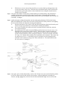
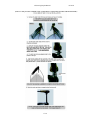
With the cover screws removed the control box cover can be lifted up and tipped to the side
to access the battery meter wires. Disconnect the red and black battery meter leads from the
speed selector (on 5-speed models) or the red and black wires exiting the control board on
variable-speed 3X motors.
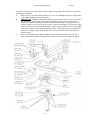
Step 3. Lift up the inner handle assembly along with the handle pivot, handle bearing, and potentiometer
(variable-speed motors) or speed selector switch (5-speed motors). Disengage the inner handle
assembly from the “D” shaft on the potentiometer/switch, remove the inner handle, and set it aside for
reassembly. (see Fig. 3)
A.
Step 4. At this point prior to further disassembly, note the routing and positioning of all electrical wiring.
When reassembling the 3X motor the wires must be placed back in the same position to avoid getting
the wires in the circular rack and pinion steering gear mechanism.
A.
Disconnect the motor wires, battery leads, and directional indicator light leads from the speed
selector switch (5-speed motors) or control board (variable-speed motors).
A-1.
On 5-speed 3X models, the switch can easily be separated from the control box when the
wires are disconnected.
A-2.
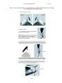
On variable-speed 3X models, loosen the Phillips pan head screw (P/N 2073414, #6-32 x 3/8”)
holding the P/N 2071905 sensor bracket in place. (Sensor bracket is located in control box
along side the potentiometer support.) Loosening the screw allows removal of the magnetic
on/off reed switch attached to wires exiting the control box. (On/off reed switch is the small
5/8” long, 3/16” diameter black cylinder with 2 small black wires attached.) Then remove the
two P/N 2073416, #8-32 x ½” socket head cap screws (located in recessed openings on the
underside of the control box) using a 9/64” allen wrench/driver. The control board is then
free to be removed. (see Fig. 3)
Fig. 3
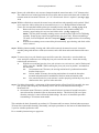
Step 5. Once again, prior to further disassembly, note how the 3X motor wires are routed and held in position
by the wire clamp located on the coupler socket retainer / indicator light bracket assembly P/N
2992900. (see Fig. 4, page 17-3) Also note how the directional indicator light wires are twisted and
17- 2