1
3X Steering Repair Manual
06/21/05
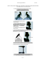
wire tied to the motor wire to prevent the indicator light wires getting in the circular rack and pinion
steering gear mechanism.
A.
Remove the P/N 2372100 phillips head screw (#8-18 x 5/8”) holding the retainer / light bracket
/ wire clamp assembly P/N 2992900 in place.
B.
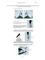
IMPORTANT – With the control box parallel to the motor lower unit, note how two sides of
the hexagon ID of the coupler socket (P/N 2070800 black coupler socket for bow mount
motors, P/N 2070801 white couple socket for transom mount motors) are parallel to / in-line
with the control box pivot screws (P/N 2073408). When reassembling a 3X motor, the coupler
socket (which drives the directional indicator) must be repositioned in this exact same manner
for proper orientation of the directional indicator arrow. (Directional arrow is parallel to the
motor lower unit pointing towards the direction of boat travel when in the water with the
motor running.)
C.
After removing the retainer / light assembly, remove the coupler socket, idler gear, idler
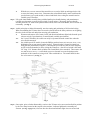
plate, and preload ring (P/Ns 2070800/2070801, 2072215, 2071900, and 2073000). (see Fig. 4)
Fig. 4
17- 3