1
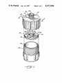
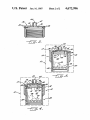
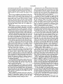
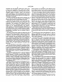
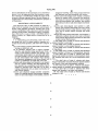
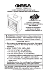
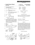
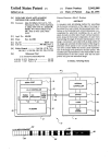
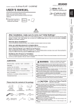
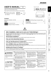
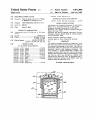
United States Patent [191
Floyd et al.
[54] SELF-REGULATING VALVE
[75] Inventors: Terry S. Floyd, Clover, S.C.; Wyatt
4,493,444
[63]
J un. 16, 1987
l/ 1985 .Del Bon et al. .
2603712
[73] Assignee: CEM Corporation, Matthews, NO
[21] APP1- N°-= 868,171
8/1977 Fed. Rep. of Germany .... .. 137/859
OTHER PUBLICATIONS
Abu-Samra et al., Analytical Chemistry, 47, 1475 (1975).
Barrett et al., Analytical Chemistry, 7, 1021 (1978).
Nadkarm, Analytical Chemistry, 56, 2233 (1984).
M,ly 22, 1986
.
4,672,996
FOREIGN PATENT DOCUMENTS
P- Barge", Jr" Matthews’ NC
[22] Filed:
Patent Number:
Date of Patent:
[11]
[45]
.
Matthews et al., Bureau of Mines Technical Progress
' Related US. Application Data
Contmuation of S61‘. NO.
Apr. 11,
Report 120 (Apr‘ 1983).
Operation and Service Manual’ Microwave Drying
aban-
doned'
/Digestion System, Model MDS-Sl, CEM Corpora
[51]
[52]
Int. 01.4 ............................................ .. F16K 15/14
U.S. Cl. .................................. .. 137/522; 137/468;
[53]
Field of Search ................. .. 220/209; ZZZ/402.21,
lion (revised M?r- 1985)
Primmy Examiner_RObeI-t G. Nilson
137/859; 220/209
Attorney, Agent, or Firm-Timothy R. Kroboth
222/494; 137/496, 468, 859, 522
[57]
ABSTRACT
References Cited
The present invention provides an improved valve.
115- PATENT DOCUMENTS
the physical environment of the valve. This valve is
[56]
Th1s valve opens and closes in response to a change in
1,925,926
9/1933 Kunkel .............................. .. 222/494
2,854,996 10/1958 Hughes
2,942,614
6/1960 Lardner
3,160,329 12/1964
Radio . . . . . . .
Particularly Suited as a relief valve in a microwave Sys
,, 137/859 x
tem-based, closed vessel digestion procedure. This
..... .. 137/859 X
valve includes a pressure-deformable, resilient wall
. . . . . .. 137/859 X
member having a ?uid vent port, and an obstructing
137/359 X
“71/859 X
member that cooperates with the wall member to open
and close the valve. Also provided is a lidded vessel
41061I254 12/1977 Nikon-‘III: .................... .. 222/494
cludes a micmweve. system and this lidded vessel’ and
4,400,401
methods using this improved valve.
3,265,034 8/1966 Wagner
318041113 4/1974 Garcea ------ "
gtfeizipard ‘ ' ' ' '
'''
employing this improved valve, an apparatus that in
8/1983 Beauvais at al_ '
4,474,211 10/1984 Lucas.
4,474,314 10/ 1984 Roggenburg ..................... .. 222/494
10 Claims, 4 Drawing Figures
ZZ
1”
.92’ 74-’?
/z
i
I
I
»
’7\\I
I
I
4!
I
754/ WI
/
/
1'”
I
/4
4;
I
I /\ 4!
4’ I
/
'
a?
,
-
.
/\/
/ __/-_--_é_—=\(=-:_?\
/
Z4
:“I: __...__
|
/
/ //
I
Z”
U. S. Patent Jun. 16,1987
Sheetl of2
I1/",
4.1
a;:5
iM
w
‘4,672,996
U. S. Patent Jun. 16,1987
Sheet2 of2
Z?
id
4,672,996
1
4,672,996
2
web with openings offset from the apertures. The Beau
SELF-REGULATING VALVE
vais et a1 patent relates to a method using microwave
energy for sterilizing and canning food products within
This application is a continuation of application Ser.
No. 722,266, ?led Apr. 11, 1985, now abandoned.
a nonmetallic enclosure cover having an aperture con
trolled by a check valve regulated by a weight. Within
the enclosure cover, a non~metallic jar with a nonmetal
lic lid having a vent hole closed by a vent closure,
TECHNICAL FIELD
contains the food product.
The present invention relates to an improved valve.
More particularly, this invention relates to a valve that
opens and closes in response to a change in the physical
environment of the valve, and that is especially useful as
a relief valve. Furthermore, this invention pertains to a
Also known in the prior art is a manually operated,
dispensing valve formed by an opening in a metallic can
lid top, a resilient rubber insert located inside the lid top
and having an outlet port portion that extends through
the lid top, and a plastic pin element. The plastic pin
lidded vessel including this improved valve, and to uses
of this valve.
BACKGROUND ART
element has a disc-like part with a raised portion that
15 seats against the rubber insert to close the valve, and has
a pin-like part that extends through the outlet port por
As exempli?ed by A. Abu-Samra et al., Analytical
Chemistry, 47, 1475 (1975), and P. Barrett et al., Analyti
cal Chemistry, 7, 1021 (1978), a microwave oven-based,
digestion technique using an acid digesting agent in an
tion of the rubber insert for engagement with a nozzle:
The valve is opened by ?nger pressure exerted against
the nozzle.
Prior work known to us is a beryllium-copper spring,
needle check valve of Lois B. Jassie and H. M. Kings
open vessel, is known. Barrett et al. report that this
procedure decreases digestion time, compared to a hot
plate heat source.
ton. This valve attaches to an outlet port of a closed
digestion vessel, as a pressure relief valve for explosion
prevention. Because the beryllium-copper spring does
Also known, as illustrated by Nadkarni, Analytical
Chemistry, 56, 2233 (1984), and S. A. Matthews et a1, 25 not absorb microwave radiation, this valve is usable in a
microwave- system-based digestion procedure. How
Bureau of Mines Technical Progress Report 120 (April
ever, a drawback is that beryllium is oxidizable, espe
1983) is a microwave oven-based, digestion technique
using an acid digesting agent in a closed system. In
cially in an acid fume environment, to beryllium oxide,
which results in the valve no longer being acceptable
Nadkarni’s procedure, a covered Te?on ® or polycar
bonate beaker was placed in a partially evacuated, 30 for use in a microwave system. Moreover, beryllium
oxide is carcinogenic.
closed, glass desiccator so that acid fumes leaking from
the covered beaker were trapped within the glass desic
cator. A polycarbonate bottle with a polypropylene
screw cap was used as a closed digestion vessel by Mat
thews et al., who cautioned against explosion caused by
Therefore, there is a need for an improved valve that
could be used as a pressure relief valve for explosion
35
prevention in a microwave system-based, closed vessel
digestion procedure. Such an improved valve would be
of even greater usefulness if it were self-closing after
excess pressure had been relieved, and thereby could
pressure build up within a closed vessel and observed
leaking of some acid fumes around the bottle caps dur
function as more than a one time pop-off valve. Such an
ing pressure dissolution. Matthews et al. report that,
improved valve would provide an even greater contri
compared to open vessel digestion, closed vessel diges
tion prevents the introduction of contaminating ele 40 bution to the art if it relieved pressure not only in re
ments and the loss of volatile elements and compounds.
sponse to a predetermined internal fluid pressure but
also in response to temperature change. Such a valve
Accordingly, although closed system digestion has
would provide an improved apparatus for microwave
been found to have advantages over open vessel diges
tion, the containing vessel in a closed system could
explode under pressure build up, with spewing of acid.
The explosion hazard is enhanced, for example, if, as in
tissue digestion, gas is generated by the digestion pro
cess. As a result, open vessel digestion is commonly
system-based, closed vessel digestion.
45
Moreover, an improved valve of this type would be
especially advantageous if it could also be manually
opened. This improved valve would be especially re
markable if the components thereof could be of the
utilized, particularly if the digestion process generates
same non-metallic material. Furthermore, such an im
gas.
A lidded digestion vessel suitable for use in a micro
proved valve would be of enhanced utility if it had a
broad range of applications.
wave system-based digestion that employs a corrosive
digesting agent, is available from Savillex Corporation
either with or without an outlet port in the lid. This
lidded vessel is formed of a deformable, resilient, highly
DISCLOSURE OF THE INVENTION
It is accordingly an object of the present invention to
55 provide an improved valve that could be used as a pres
chemically inert, thermoplastic material. This material
sure relief valve for explosion prevention in a micro
is a ?uorocarbon copolymer in which the carbon-?uo
rine backbone in the main chain is connected with per
wave system-based, closed vessel digestion procedure.
?uorocarbon copolymer is marketed by Dupont Corp.
It is a further object of the present invention to pro
vide an improved relief valve that is self-closing after
excess pressure has been relieved, and thereby functions
under the trademark Te?on ® PFA.
as more than a one time pop-off valve.
fluoroalkoxy side chains through oxygen links. This
It is an even further object to provide an improved
Prior art valves are exempli?ed by U.S. Pat. Nos.
valve that relieves pressure not only in response to a
4,474,211 to Lucas, 4,493,444 to Del Bon et al, and
predetermined internal fluid pressure but also in re
4,400,401 to Beauvais et al. The Del Bon et al patent is
directed to a self-closing valve-and-lid assembly. The 65 sponse to temperature change.
It is a still further object to provide an improved
Lucas patent pertains to a valve that includes a disc-like
apparatus for microwave system-based, closed vessel
member through which apertures extend, and an aper
digestion utilizing this valve.
ture closing device having a pressure responsive flex
3
4,672,996
4
It is an even additional object to provide an improved
valve the components of which may be non-metallic
embodiments, and its several details are capable of mod
i?cation in various respects, all without departing from
the invention. Accordingly, the drawing and the de
tailed description are to be regarded as illustrative in
and of the same material.
nature, and not as restrictive.
It is an additional object to provide an improved
valve of this type that can be manually opened.
It is another object to provide an improved valve
having a broad range of applications.
Additional objects, advantages and novel features of
the present invention are set forth in the description that
follows, and in part will become apparent to those
skilled in the art upon examination of the following
description or may be learned by practice of the inven
tion. The objects and advantages of the invention may
be realized and attained by means of instrumentalities
BRIEF DESCRIPTION OF THE DRAWING
Reference is now made to the accompanying draw
ing, which forms a part of the speci?cation of the pres
ent invention, and which depicts preferred embodi
and combinations particularly pointed out in the ap
ments of an improved valve in accordance with the
present invention and uses of the improved valve.
FIG. 1 is an isometric view of the components of a
lidded vessel employing a very highly preferred em
bodiment of a valve in accordance with the present
pended claims.
invention;
To achieve the foregoing objects and in accordance
FIG. 2 is a cross-sectional view of the lid of the lid
ded vessel of FIG. 1 along the line 2—2;
with the purpose of the present invention, as embodied
FIG. 3 is a sectional view of the assembled lidded
and broadly described herein, there is provided a valve
responsive to a predetermined internal ?uid pressure. 20 vessel and member 12 of FIG. 1 taken in a plane
through the central assembly axis, showing the valve in
This valve includes a pressure-deformable, resilient wall
closed position and depicting contents in phantom
member having a ?uid outlet port. The valve further
includes an obstructing member engaged in a tight seal
within the lidded vessel; and
ing relationship with an inside surface of the wall mem
FIG. 4 is a sectional view identical to that of FIG. 3,
ber or with an inner surface of the outlet port. As a 25 except that the valve is shown in open position in re
sponse to a certain ?uid pressure within the lidded ves
result, out?ow through the outlet port is blocked when
sel.
internal ?uid pressure impinging on the wall member is
insufficient to cause deformation thereof that over
BEST MODE FOR CARRYING OUT THE
INVENTION
comes the tight sealing relationship.
The wall member is sufficiently pressure-deformable
that the force of the predetermined internal ?uid pres
As explained earlier, the present invention is directed
to an improved valve. More particularly, this invention
relates to a self-regulating valve that opens and closes in
response to a change in the physical environment of the
valve, in particular to a change in internal ?uid pres
sure. In a preferred embodiment, this improved valve is
also temperature sensitive, and therefore able to re
spond not only to internal ?uid pressure but also to
sure acting thereon, causes deformation thereof that
overcomes the tight sealing relationship, thereby open
ing the valve to permit pressure relief through the outlet
port. The resiliency of the ?uid pressure-deformed, wall
member is suf?cient to cause the wall member to reen
gage in the tight sealing relationship when internal ?uid
pressure impinging on the wall member becomes less
than the predetermined internal ?uid pressure, thereby
temperature change. In this embodiment, the compo
closing the valve. Accordingly, this valve opens and 40 nents of the valve can amazingly be made of the same
closes in response to a predetermined internal ?uid
material. Also in this embodiment, the valve is micro
pressure. In a preferred embodiment, this valve is sensi
tive not only to internal ?uid pressure but also to tem
wave radiation transparent and is therefore useful as a
perature.
digestion technique, even when the digestion generates
gas. In a very preferred embodiment, the improved
valve is highly chemically inert and accordingly corro
Also provided by the present invention is a lidded
vessel that employs the improved valve of the present
invention.
In addition, there is provided an apparatus that in
cludes a microwave system and a lidded vessel employ
ing the improved valve of the present invention. In a
preferred embodiment, the microwave system includes
a corrosion resistant chamber, a corrosion resistant
exhaust system capable of providing high volume air
?ow through the chamber, an element for absorbing
excess re?ected radiation, and a computer-controlled
variable power source. The lidded vessel is microwave
transparent.
Also provided by the present invention are methods
using the improved valve of the present invention.
relief valve in a microwave system-based, closed vessel
45
sion resistant. Also in a preferred embodiment, the im
proved valve of this invention can be manually opened.
Also as explained earlier, our invention is directed to
a lidded vessel employing this improved valve, to an
apparatus including a microwave system and this lidded
vessel, and to methods using the improved valve.
The term “?uid” as used in our description of the
present invention and in the claims, means a liquid, gas
or vapor, and the terms “upper”, “lower”, “above”,
“below”, “upward” and “downward” are intended to
designate relative orientation of the valve as shown in
the Figures.
FIGS. 1, 3 and 4 depict a lidded vessel 10 utilizing a
These methods include use in canning a food product, 60 very highly preferred embodiment of a valve 12 in
sterilizing an object, and dispensing a ?uid at a desired
accordance with the present invention. Valve 12 is
temperature.
formed by a disc-shaped member 14, and a deformable,
In the drawing and in the detailed description of the
resilient top wall 16 of a lid 18 of a hollow receptacle or
invention that follows, there are shown and essentially
container 20. Centrally located in the lid is a ?uid outlet
described only preferred embodiments of this invention, 65 port 22. Lid 18 includes an upright sleeve 23 that ex
simply by way of illustration of the best mode contem
tends the outlet port above wall member 16.
plated by us of carrying out this invention. As will be
Preferably, disc-shaped member 14 and the entirety
realized, this invention is capable of other and different
of lidded vessel 10 are formed of a deformable, resilient,
5
4,672,996
thermoplastic material, that is very preferably the same
for each of member 14, the lid and the container. Even
more preferably, this material is the ?uorocarbon co
polymer described earlier. Preferably, the cross-sec
tional thickness of disc 14 imparts semi-rigidity to the
disc.
Disc 14 has a peripheral wall surface 24 that con
forms to an upper inside wall surface 26 of the lid, and
enables the disc to be locked in place between the lid
and an upper rim 28 of container 20. Encircling, and
spaced apart from, a center 30 of the disc is a raised
abutment ring 32 having a peak 34, which provides
point contact between the disc and an inner surface 36
of lid top 16. As can best be seen in FIG. 1, located
between ring 32 and peripheral wall surface 24 are aper
tures 38, each having a ?ow area “A”, de?ned by a
diameter “a”.
With reference to FIG. 3, which shows valve 12 in
closed position, the abutment ring peak of semi-rigid
6
Should the force of the internal ?uid pressure imping
ing on the lid top again exceed the pressure of the abut
ment ring against the lip top, valve 12 will reopen, until
the ?uid pressure within the lidded vessel drops suf?
ciently for the valve to reclose. Thus, opening and clos
ing of the valve in response to the internal ?uid pressure
within the lidded vessel, recurs as required.
The internal ?uid pressure required to open valve 12
is controlled by factors including the height and the
diameter of abutment ring peak 34, and the flexibility of
the lid top. For example, the greater the height of peak
34, the relatively greater the pressure needed; the
greater the diameter of the ring peak, the relatively
greater the pressure required; and the more ?exible the
lid top, the relatively less pressure needed. Accord
ingly, by selection for example of an appropriate peak
height or ring peak diameter, the valve can be made to
open at a predetermined internal pfessure.
Attention is invited to our later description, which
disc 14 pushes against ?exibly deformable, lid top 16 so 20 illustrates the relationship between diameter of the ring
as to cause the lid top to bulge outwardly. Outward
bulging of the lid top is seen by comparison to the undis
torted lid shown in FIG. 2. The point contact provided
by the abutment ring peak produces a tight sealing rela
tionship between ring 32 and inner lid top surface 36.
Peak 34 is appropriately spaced apart from center 30
of the disc such that it surrounds outlet port 22 of the
lid, thereby obstructing ?ow through the outlet port.
The outlet port and abutment ring could be offset from
the central assembly axis, provided that they are so
peak and the internal pressure needed to open valve 12.
As described later, valve 12 is responsive not only to
internal ?uid pressure but also to temperature change.
If disc 14 were ?exible, rather than semi-rigid, the
25 disc would be seen bowed downwardly in FIG. 3 and
lid top 16 would show less outward bulging. For a
constant height of peak 34 and diameter of ring 32, a
relatively higher internal pressure would be needed to
open valve 12, if the disc were ?exible, rather than
semi-rigid. If, on the other hand, the disc were rigid
located relative to one another in the assembled valve,
rather than semi-rigid, internal pressure pushing against
that the abutment ring peak surrounds the outlet port.
central area 43 of the lower disc surface would not
As shown in FIGS. 3 and 4, disc 14 divides lidded
vessel 10 into compartments 40 and 42. Apertures 38
permit internal fluid pressure to be equally exerted
against lid top 16 and other walls of the lidded vessel.
The number of apertures, whether one or many, is not
strengthen the tight sealing relationship between peak
34 and inner top surface 36. When the disc is ?exible,
the internal pressure required for valve opening is less
predictable than when the disc is rigid or semi-rigid.
When used with a lidded vessel, valve 12 is operable
regardless whether a small volume of liquid is used, or
the lidded vessel is ?lled to capacity.
critical; rather, the sum of areas “A” of the apertures
should not restrict ?ow to the cap.
So long as the force of the internal fluid pressure 40 Advantageously, valve 12 can be manually opened by
exerting ?nger pressure against an outer wall 47 of
acting on lid top 16 is less than or only equal to the
sleeve 23 in a direction generally perpendicular to the
pressure of abutment ring 32 against the lid top, valve
12 remains closed. Internal ?uid pressure pushing
central assembly axis of the valve. This type of ?nger
pressure will move inner lid top surface 36 out of the
assists the mechanical pressure exerted by the abutment 45 tight sealing relationship with the abutment ring peak.
Valve 12 can be maintained open by pressure exerted
ring to strengthen the tight sealing relationship between
through the outlet port on an upper disc surface 48.
peak 34 and inner top surface 36. Hence, the force of
FIGS. 3 and 4 depict lidded vessel 10 containing in
internal ?uid pressure is utilized to enhance closure of
phantom, solids 49 and a liquid 50, to which microwave
the valve. Central area 43 is de?ned by a diameter “f” of
50 energy is applied by means of a microwave 51, also
the abutment ring peak.
shown in phantom. Solids 49 may be, for example, a
A donut-shaped area 45, which consists of the area of
sample to be digested such as a gas-generating tissue
inner lid top surface 36 outside the abutment ring peak,
sample. In this case, liquid 50 would be a digesting agent
is conveniently greater than central area 43. Since the
such as an acid digesting agent. Solids 49 may also be a
lid top is more ?exible than the disc, central area 43
55 food product to be canned using microwave energy, in
could be greater than area 45.
which case liquid 50 would contain water; or solids 49
If, as illustrated in FIG. 4, the force of the internal
may be objects to be sterilized using microwave energy,
?uid pressure impinging on lid top 16 should exceed the
in which case liquid 50 would include water.
pressure of abutment ring 32 against the lip top, the lid
To take advantage of the manual release feature of
top is lifted away from sealing contact with abutment
valve 12, lidded vessel 10 could contain a ?uid to which
ring peak 34, and valve 12 is opened. A gap 46 is created
microwave energy is applied to heat the ?uid and build
between peak 34 and inner lid top surface 36, through
up internal pressure for manual release of the warm or
which pressure is released from the lidded vessel, via
hot ?uid. Exemplary ?uids include, but are not limited
?uid outlet port 22.
to, a gas, a foam, a semi-?uid mixture such as a slurry, or
When a suf?cient reduction in the force of the inter
nal ?uid pressure acting on the lid top has occurred, the 65 a liquid such as a semi-solid or an emulsion. Illustrative
semi-solids include gels and pastes.
resiliency of deformable, resilient top wall 16 causes
For example, container 20 could be filled with a suit
disc 14 and inner lid top surface 36 to reseat in a tight
able shaving cream composition, and the lidded vessel
sealing relationship, thereby closing the valve.
against a central area 43 of a lower disc surface 44,
7
4,672,996
8
assembled with disc-shaped member 14 in place. The
internal pressure. In comparison, if the diameter across
contents of the assembled vessel could then be heated
the ring peak is 2 inch, the valve opens at approximately
80 psi internal pressure, and if the ring peak diameter is
5,1 inch, the valve opens at about 95 psi internal pressure.
by microwave radiation for a desired period of time.
The lidded vessel could then be inverted, and valve 12
A valve in accordance with the present invention in
manually opened to release a warm or hot shaving
cream composition. It will be appreciated that the lid
which the pressure-deformable, resilient wall member is
ded vessel is re?llable, as the lid could be removed and
additional material could be added to the container for
made of a thermoplastic material, is not only pressure
sensitive but also temperature sensitive: as the tempera
dispensing or discharge.
ture of the pressure-deformable wall member increases,
elasticity of the material thereof increases, and the valve
It will be noted that the ?uid pressure opening valve
12 is in the same upward direction as the mechanical
opens at a relatively lower pressure. For example, as
pressure being exerted on deformable lid top 16.
just described, when the disc of valve 12 has a ring peak
diameter of % inch, the valve opens at about 60 psi for
water. In this instance, vapors within the lidded vessel,
Preferably, the same material is used to form all com
ponents of our improved valve. As a result, one valve
component will not become hotter than another valve
component. The containers of the lidded vessels of
result in top wall 16 of the lid being at a temperature of
approximately 150° C. In contrast, if a liquid were used
FIGS. 1 and 3-6 are preferably formed of the same
having a boiling point appropriate for producing a lid
material as the pressure-deformable wall member,
which results in a vessel-protecting effect. However, in
some applications, a valve in accordance with the pres 20
ent invention is used with a container formed of a differ
ent material. For example, the valve could be formed of
top temperature of about 60° C., the valve would open
at approximately 110 psi internal pressure.
When using valve 12 for closed vessel digestions, the
manual opening feature of the valve makes it possible to
check for high pressure within the closed vessel, prior
thermoplastic components, but the container could be
formed of glass.
ple.
to opening the closed vessel to remove a digested sam
For use in a microwave system, the improved valve 25
of the present invention should be microwave radiation
transparent. This characteristic is achieved if the valve
is made of a microwave transparent, thermoplastic ma
digesting agent fumes may escape. However, when the
digestion generates a gas, opening and reclosing of the
valve will be bene?cial.
terial. Preferably, the same material is used to form all
valve components. Exemplary microwave transparent,
In carrying out a closed vessel digestion, it will gen
erally be undesirable for the relief valve to open, as
30
As can be seen, a valve in accordance with the pres
thermoplastic materials include, but are not limited to,
ent invention, is capable of containing a high pressure,
polypropylene, polyethylene, polypropylene/polyethy
that is, a pressure of more than about 50 psi. Accord
ingly, the improved valve makes possible a closed ves
lene copolymers, and the ?uorocarbon copolymer de
scribed earlier. The ?uorocarbon copolymer advanta
geously provides a high temperature, corrosion resis
35 lidded vessel walls being an important limitation on the
tant valve.
As later described in more detail, a valve in accor
out of a bottom wall of a Savillex lidded digestion vessel
sel digestion at high pressure, with the strength of the
internal pressure. For example, we experienced a blow
dance with the present invention is temperature sensi
at about 150 psi. In contrast, the prior art, closed vessel
tive when the pressure-deformable wall member thereof
digestion procedures described earlier, experienced
is made of a thermoplastic material. Illustrative thermo 40 leakage at considerably lower pressures. High pressure
plastic materials for providing a temperature sensitive
digestions should further reduce digestion time.
valve include those just described. Advantageously, a
A thermoplastic lidded vessel such as vessel 10 may
be heat treated to reduce deformability of the walls
useful thermoplastic material is moldable and precision
machinable.
thereof. Heat treating or annealing is carried out at an
An eminently useful microwave system for digestion 45 appropriate temperature for a suitable period of time to
obtain walls having the desired reduced deformability.
procedures is characterized by a corrosion resistant
interior chamber, a corrosion resistant exhaust system
capable of providing high volume air ?ow through the
chamber, means for absorbing excess re?ected radia
tion, and a computer-controlled variable power source.
A microwave system of this type is commercially avail
able under the trademark MDS-8l from CEM Corpora
tion, Matthews, N.C.
Further details of the present invention are now pro
vided based on trials carried out in an MDS-8l micro
wave system, using a valve in accordance with the
present invention as a relief valve for a lidded digestion
For example, lidded vessel 10 could be heated at about
200° C. for about 72 hours.
The self-regulating valve of the present invention can
be also used with a microwave system for enabling
chemical starting materials to be reacted at a desired
pressure and temperature, and dispensing or discharg
ing the reaction product at a desired temperature; or for
simply dispensing or discharging a ?uid at a desired
temperature. Exemplary ?uids include, but are not lim
ited to, a gas, a foam, a semi-?uid mixture such as a
slurry, or a liquid such as a semi-solid or an emulsion.
vessel obtained from Savillex Corporation. Water is
Illustrative semi-solids include gels and pastes. Use of
the valve for dispensing or discharging a ?uid at a de
added to the vessel, the lid of which is provided with a
vent port, and the lidded vessel is assembled with semi 60 sired temperature avoids the need for temperature-sens
rigid, disc-shaped member 14 in place, to form valve 12.
ing devices and related temperature-actuated devices.
Member 14, which is made of the thermoplastic ?uoro
The manual release feature of, for example, valve 12
carbon copolymer described earlier, has an abutment
may also be used for discharging, for purposes of illus
ring peak that is 0.062 inch high, and four apertures
tration, a pressured ?uid, such as grease, from a hose or
equally spaced around the abutment ring each with a 65 conduit, on one end of which disc-shaped member 14
diameter of 5 inch. The lower disc surface has a diame
and a closure element are in place.
ter of 1.53 inches. When the diameter of the abutment
In the preceding description of the present invention,
there are shown and essentially described only pre
ring peak is % inch, this valve opens at about 60 psi
9
4,672,996
10
pingement-enabling means being located between
said abutment and said peripheral wall surface;
ferred embodiments of this invention, but as mentioned
above, it is to be understood that the invention is capa
ble of changes or modi?cations within the scope of the
wherein said dome-shaped wall member comprises
inventive concept expressed herein. Several changes or
modi?cations have been brie?y mentioned for purposes
of illustration.
means for manual relief of internal ?uid pressure,
said means for manual relief being a sleeve integral
with said dome-shaped wall member, that extends
said outlet port above said dome-shaped wall mem
INDUSTRIAL APPLICABILITY
ber;
The improved valve of this invention is useful as a
wherein said dome-shaped wall member is suf?
ciently ?uid pressure-deformable that said certain
internal ?uid pressure acting thereon, breaks said
valve seal to permit out?ow through said outlet
port; and
wherein the ?uid pressure-deformed, wall member is
sufficiently resilient that said valve seal is reformed
when internal ?uid pressure becomes less than said
relief valve, for example, in a microwave system-based,
closed vessel digestion procedure. Further uses of the
valve in combination with a microwave system, include
canning a food product, sterilizing an object, or dispens
ing a ?uid such as a gas, a foam, a semi-?uid mixture
such as a slurry, or a liquid such as a semi-solid or an
emulsion.
We claim:
1. A self-opening and self-closing relief valve for
certain internal ?uid pressure.
2. The relief valve of claim 1, wherein said abutment
providing ?ow out of a closed system in response to a
support member is semi-rigid.
certain internal ?uid pressure, said relief valve compris
3. The relief valve of claim 1, wherein said abutment
support member is a disc-shaped element.
4. The relief valve of claim 1, wherein said abutment
mg
(a) a dome-shaped, pressure-deformable wall member
having an outlet port, and
(b) an abutment integral with a support member
is ring-shaped.
5. The relief valve of claim 1, wherein said abutment
support member is formed of a thermoplastic material.
6. The relief valve of claim 1, wherein said dome
shaped wall member is formed of a thermoplastic mate
rial, whereby said relief valve is also temperature sensi
tive.
7. The relief valve of claim 1, wherein said dome
shaped wall member and said abutment support member
are formed of the same thermoplastic material.
8. The relief valve of claim 7, wherein said thermo
therefor, said abutment being spaced apart from a
center of said support member and having a cir
cumferential peak adapted to surround said outlet
port and forming a valve seal with an inside surface
of said dome-shaped wall member when internal
?uid pressure impinging on said dome-shaped wall
member is insufficient to break said valve seal;
wherein said dome-shaped wall member is an integral
part of a closure element, and said abutment sup
port member has a peripheral wall surface that is
adapted to interlock with, and that is in an inter 35 plastic material is moldable and precision machinable.
9. The relief valve of claim 1, wherein said dome
locking relationship with, an inside wall surface of
shaped wall member is an outer wall member.
said closure element;
10. The relief valve of claim 1, wherein said closure
wherein said abutment support member comprises
element is a lid.
means for enabling internal ?uid pressure impinge
*
*
l‘
*
ii
ment on said dome-shaped wall member, said im
45
55
60
65
UNITED STATES PATENT AND TRADEMARK OFFICE
CERTIFICATE OF CORRECTION
PATENTNO.
:
4,672,996
DATED
:
June 16, 1987
INVENTOFHS) :
TERRY s .
FLOYD
It is certified that error appears in the above-identified patent and that said Letters Patent is hereby
corrected as shown below:
On the Title Page, Item [191
"Floyd at 81- Should read
—- Floyd -.-.
Item [75] Inventors, should read [75] Inventor:
-- Terry S.
Floyd ——.
Signed and Sealed.v this
Twelfth Day of January, 1988
Attest:
DONALD J. QUIGG
_ Arresting O?‘icer
-
Cammissioner of Patents and Trademarks