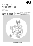
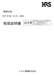
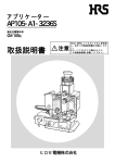
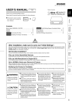
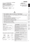
1
アプリケーター/APPLICATOR
AP105‑TM11P‑66P
適合圧着機本体/Main unit of applicable crimping machine
CM‑105
取扱説明書 / INSTRUCTION MANUAL
注意
安全に使用していただくために使用前に、必ずこの取扱説明書をお読み下さい。
また、いつでもすぐに読めるように、この取扱説明書を保管して下さい。
CAUTION :
Be sur e to r ead this Instr uction Manual carefully befor e using it to secur e safety in oper ation.
In addition, save this Instr uction Manual so that it is available whenever necessar y for r eview.
ヒロセ電機株式会社
HIROSE ELECTRIC CO., LTD.
安全にご使用していただくために
本機は、圧着作業上やむをえず機械の可動部品の近くで作業するため、可動部品に抵触してしまう可
能性が常に存在していますので、実際に実際にご使用されるオペレータの方および、保守、修理等を
される保全の方は、以下の 安全についての注意事項 を熟読されて、怪我などされないようにご使用
下さい。
なお、本取扱説明書および、警告表示の内容を十分に理解し、指示を守って下さい。
( I )警告表示の説明
危険
警告
注意
取り扱いを誤った場合に、使用者が死亡または重傷を負う危険が切迫
して生じることが想定される場合。
取り扱いを誤った場合に、使用者が死亡または重傷を負う可能性が想
定される場合。
取り扱いを誤った場合に、使用者が傷害を負う危険が想定される場合
および物的損害のみの発生が想定される場合。
※ 損害の程度の分類は、以下を参考とする。
重
傷 :
傷
害 :
物的損害 :
失明、けが、やけど(高温・低温)、感電、骨折、中毒などで、後遺症が残るもの
および治療に入院・長期の通院を要するものを言う。
治療に入院や長期の通院を要さない、けが、やけど、感電などを指す。
家屋・家財および家畜・ペットにかかわる拡大損害を指す。
i
安全についての注意事項
注意
基本的注意事項
1. ご使用される前に本取扱説明書および、付属に入っている全ての説明書類を必ずお読み下さい。また、
いつでもすぐに読めるように、この取扱説明書を大切に保存して下さい。
安全装置
1. 安全装置の欠落による事故を防ぐため、この機械を操作する際は、安全装置が所定の位置に正しく取り
付けられている事を確認してから操作して下さい。安全装置についてはⅲ頁を参照して下さい。
2. 安全装置を取り外した場合は、必ず元の位置に取り付け、正常に機能することを確認して下さい。
用 途
1. この機械は、本来の用途および本取扱説明書に規定された使用方法以外には使用しないで下さい。用途
以外の使用に対しては、当社は責任を負いません。
2. 機械には、改造等を加えないで下さい。改造によって起きた事故に対しては、当社は責任を負いません。
教育訓練
1. 不慣れによる事故を防ぐため、この機械の操作についての教育、並びに、安全に作業を行うため雇用者
による教育を受け、適性な知識と操作技能を有するオペレータのみが、この機械をご使用下さい。その
ため雇用者は、事前にオペレータの教育訓練の計画を立案し、実施することが必要です。
作業時の服装
1. 衣類の巻き込みによる人身への事故を防ぐため、作業服を着用し袖口等のボタン、前開きのファスナー
等は必ずとめて下さい。
2. 頭髪は帽子の着用等をして巻き込みの危険がないようにして下さい。
3. 履物はかかとが固定できるシューズ等を着用して下さい。
各使用段階に於ける注意事項
運 搬
1. 移動の際は転倒、落下事故を起こさないよう十分安全策をとって下さい。
2. 予期せぬ事故や、落下事故を防ぐため、再梱包をする場合は、着荷時と同じ状態もしくは、同等以上
の状態に再梱包して下さい。特に機械に付着した油は、十分に拭き取ってから再梱包して下さい。
開 梱
1. ダンボールでの梱包です。開梱の際は、落下に注意し慎重に取り出して下さい。
給
1.
2.
3.
油
機械には、当社指定オイルまたは同等品を使用して下さい。
炎症、カブレを防ぐため、目や身体に油が付着した時は直ちに洗浄して下さい。
下痢、嘔吐を防ぐため、誤って飲み込んだ場合、直ちに医師の診断を受けて下さい
保 守
1. 不慣れによる事故を防ぐため、修理、調整は機械を熟知した保全技術者が本取扱説明書の指示範囲で
行って下さい。また、部品交換の際は、当社純正部品を使って下さい。不適切な修理・調整および非
純正部品による事故に対しては、当社は責任を負いません。
2. 人身事故を防ぐため、修理調整・部品交換等の作業後は、ねじ・ナット等が緩んでいないことを確認
して下さい。
3. 機械の使用期間中は、定期的に清掃を行って下さい。この際、不意の起動による事故を防ぐため、電
源は必ず切ってから行って下さい。
4. 人身事故を防ぐため、修理・調整した結果、正常に動かない場合は直ちに操作を中止し、当社に連絡
し、修理依頼して下さい。
ii
アプリケーターAP105‑TM11‑
66Pを
より安全にご使用していただくための注意事項
1. 巻き込みによる人身への事故を防ぐため、可動部分および可動部近くには、指、頭髪、衣
類等を近づけたり、不要な物は置かないで下さい。
注意
安全装置について
ここに記載されている機械および安全装置はあくまで、日本国内仕様として製造された機種およびそれに装着・
同梱された安全装置であり、仕向地、仕様により異なる場合もあります。
アプリケーター側
本体側
フライホールカバー
フライホール等による
警告ラベル
安全カバー
指とプレス部の接触を防
カバー内には回転物があ
止するカバーです。
り、巻き込み、挟み込み
手・頭髪の巻き込みを防止
するカバーです。
の危険あり。
警告ラベル
触ると火傷をすることが
ある。
警告ラベル
内部に電装部があり、感
電の危険あり。
ご使用上の注意
圧着機操作時の、最低限
の注意が記載されていま
す。
警告ラベル
フートスイッチカバー
指を切断する危険あり、
足への危険を防止するカ
安全カバー内には絶対指
バーです。
を入れない事。
iii
FOR SAFE OPERATION
Because of the machine’s design, there is always a possibility of contact with moving par ts. The oper ator s of the
machine and the maintenance per sonnel who are in char ge of maintenance and r epair wor k are r equired to r ead the
following SAFETY INSTRUCTIONS so as to avoid injur y.
To fully under stand the descr iptions given in this Instr uction Manual and the war ning labels attached on the
machine, the war ning messages ar e used in accor dance with the below-stated classification. Please be sure to
thor oughly under stand the messages and follow the instructions.
(I) Description of warning messages
DANGER
Misuse of the tool will expose the oper ator to immediate danger of major injur y or
death.
Misuse of the tool may expose the operator to danger of major injur y or death.
WARNING
CAUTION
Misuse of the tool may expose the oper ator to danger of injur y and may cause
damage to pr oper ty.
* Deter mine the degree of impair ment referr ing to the below-stated classification.
Major injur y
: Loss of eyesight, wounds, bur ns (hyperther mal and hypother mal bur ns), electric shocks, fr actur e of a bone,
poisoning, etc. r equiring emer gency tr eatment or extended medical care.
Injur y (Minor injur y) : Wounds, bur ns, electr ic shocks, etc. requir ing medical tr eatment.
Damage to pr operty
: Damage to the machiner y and or the surr ounding ar ea.
iv
SAFETY INSTRUCTIONS
CAUTION
Basic safety instr uctions
1. Be sur e to r ead this Instruction Manual and all the instr uctions and other mater ials supplied with the unit as
accessor ies. Save this Instr uction Manual and make it available for r eview whenever necessar y.
Safety device and war ning labels
1. To avoid possible accidents due to lack of the safety device, be sur e to oper ate the machine after ascertaining that the
safety device is pr oper ly installed at the pr edeter mined position. Refer to page vi for detailed descr iption of the safety
device.
2. Once the safety device is detached fr om the machine, r eplace it to its original position and check to be sure that it
pr oper ly functions.
Application
1. This machine shall only be used for its or iginally intended pur pose while following the instr uctions specified in this
Instr uction Manual.
2. Modifications to this machine is pr ohibited. We assume no r esponsibility for accidents r esulting fr om modifications.
Tr aining
1. To pr event possible accidents caused by unfamiliar ity with the oper ation of the machine, the machine shall only be
allowed to be used by the oper ator s who have been tr ained for pr oper oper ation and pr ovided with sufficient knowledge
of safe operation by the employee. For this pur pose, the employer shall establish a tr aining plan and implement it for
the oper ator s befor ehand.
Wor king wear
1. To pr otect against possible accidents resulting in per sonal injur y by your cloths being caught in the machine, be sur e
wear a wor k unifor m and secur ely fasten buttons on the sleeve cuffs and close the zipper on the top center plait of the
unifor m, if any. Avoid wearing loosely fitted clothing.
2. The oper ator should fasten hair secur ely to avoid his/her hair from being caught in the machine.
3. The oper ator should wear close toe, rubber sole shoes.
Safety instr uctions in each categor y of wor k following
the deliver y of the machine
Tr anspor tation
1. The machine shall be moved in such a way that secures safety avoid falling and dr opping.
2. To protect against unexpected accidents or drop accidents, the machine shall be repackaged, if necessary, to achieve the
originally delivered state or better. Prior to repackaging, wipe off oil gathering on the machine.
Unpacking
1. The machine is shipped in a cor r ugated car dboar d box. Be sure to take the machine out from the box while cautiously
avoiding dropping the machine.
Lubr ication
1. Use oil of the kind designated by us or an equivalent for the machine.
2. In the event that oil should get in your eye or contact your skin, immediately wash to remove it to protect against
ir ritations and r ashes.
3. In the event that you should swallow oil by mistake, immediately consult a doctor to prevent diarr hea and emesis.
Maintenance
1. To prevent possible accidents caused by unfamiliar ity with the oper ation of the machine, repair and adjustment of the
machine shall be conducted only by maintenance per sonnel who have a full knowledge of the machine. Any repair and
adjustment beyond the r ange covered by the instr uctions given in this Instr uction Manual is prohibited. We assume no
responsibility for accidents caused by improper repair or adjustment or the use of non-genuine part(s).
2. To protect against per sonal injur y, check to be sure that screws and nuts are not loosened after the completion of
repair /adjusting wor ks and replacement of parts.
3. Per iodically clean the machine as long as it is commissioned. To prevent possible accidents caused by abr upt star t of
the machine dur ing cleaning, be sure disconnect the machine prior to cleaning.
4. In the event that your machine fails to per for m nor mally after repair or adjusting immediately stop operation and
contact us for ser vice so as to protect against per sonal injur y.
v
SAFETY INSTRUCTIONS TO BE FOLLOWED WHEN USING
THE APPLICATOR MODEL AP105
CAUTION
1. To avoid possible accidents resulting in per sonal injur y caused by being caught in the
moving par ts of the machine, extreme caution has to be taken to keep your hands, head
and finger s away from the moving par ts and the area sur rounding them. Also, do not
place any matter that is not necessar y in the use of the machine near-by.
Safety device
For the machine and the safety device of which configurations are given below, the machine is made to specifications
intended for Japanese home market and the safety device is mounted on and supplied with the machine. The configurations
may differ with destinations and specifications.
Applicator
Main unit
Flywheel cover
War ning label
Safety cover
A rotating component is
installed inside the cover.
Danger of contact injury is
present.
The cover prevents contact
between fingers and the press.
The cover prevents contact of
hands, head, etc. by the
flywheel, etc.
War ning label
If touching, you could get
burns.
War ning label
Electrical components are
installed inside. Danger of
electric shocks is present.
Safety instr uction in use
The minimum safety
instructions to be followed
when operating the crimping
machine are indicated.
War ning label
Danger of cuts on fingers is
present. Never place fingers
inside the safety cover.
vi
Foot switch cover
The cover protects feet
against hazards.
目
次
1. 型式 ..........................................................................................................................1
2. 仕様 ..........................................................................................................................1
3. 各部の名称...............................................................................................................1
4. アプリケーターの取り付け、取り外し方法 ........................................................2
4‑1. 圧着機本体への取り付け..........................................................................................................................2
4‑2. 圧着機本体からの取り外し.....................................................................................................................3
5. 圧接作業...................................................................................................................4
5‑1. 電線の準備.....................................................................................................................................................4
(1)端末加工................................................................................................................................ 4
(2)ケーブル加締め ..................................................................................................................... 7
5‑2. 圧接作業準備 ................................................................................................................................................8
(1)圧接作業方法......................................................................................................................... 8
(2)圧接ハイトの調整方法........................................................................................................... 9
6. 圧接品質...............................................................................................................10
6‑1.圧接品質基準.............................................................................................................................................. 10
7. メンテナンス.......................................................................................................11
7‑1. 給油 ........................................................................................................................................................... 11
7‑2. 日常のお手入れについて ................................................................................................................... 11
7‑3. 消耗部品の交換...................................................................................................................................... 12
7‑4. 消耗部品一覧表...................................................................................................................................... 12
8.トラブル処置.........................................................................................................13
8‑1. 圧接品質上トラブル.............................................................................................................................. 13
9. 付録 ......................................................................................................................14
9‑1 .主要部品名称 ............................................................................................................................................ 14
CONTENTS
1. MODEL.......................................................................................................................1
2. SPECIFICATIONS ....................................................................................................1
3. CONFIGURATION ...................................................................................................1
4. MOUNTING/REMOVING THE APPLICATOR ....................................................2
4-1. Mounting the applicator to the crimping machine................................................................................2
4-2. Removing the applicator fr om the crimping machine..........................................................................3
5. CRIMPING PROCEDURES .....................................................................................4
5-1. Cable Preparation ............................................................................................................................................4
(1) Termination .................................................................................................................................. 4
(2) Crimping the cables ....................................................................................................................... 7
5-2. Preparation for Crimping .............................................................................................................................8
(1) Crimping Procedure....................................................................................................................... 8
(2) Adjusting the crimping height ......................................................................................................... 9
6. CRIMPING QUALITY..........................................................................................10
6-1. Crimping Quality Standard..................................................................................................................... 10
7. MAINTENANCE ...................................................................................................11
7-1. Lubrication.................................................................................................................................................... 11
7-2. Daily maintenance....................................................................................................................................... 11
7-3. Replacing the consumables ...................................................................................................................... 12
7-4. List of consumables .................................................................................................................................... 12
8. TROUBLESHOOTING .........................................................................................13
8-1. Poor crimping quality................................................................................................................................ 13
9. APPENDIX .............................................................................................................14
9-1 .Part list ........................................................................................................................................................... 14
1. 型式/MODEL
製品番号/Product No.
HRS.No.
AP105-TM11P-66P
CL901-0938-4
2. 仕様/SPECIFICATIONS
項目/Item
圧接ハイト調整/
Crimping height adjustment
外形寸法(ラム下死点時)/
External dimensions
(with ram at the bottom dead center)
重量/Weight
適合プラグ/Applicable plug
仕様/Specification
ダイヤル回転式 8 段階調整/
Dial, 8-step adjustment
縦(高さ)170 mm X 横 170 mm X 奥行き 80 mm/
170 mm (H) x 170 mm (W) x 80 mm (D)
5kg
TM11P-66P (50) (CL222-2149-9(50))
3. 各部の名称/CONFIGURATION
シャンク/Shank
ワイヤ−デスク/Wire desk
スペーサーデスク/Spacer desk
ラム/Ram
安全カバー/Safety cover
ストッパー/Stopper
ホルダー/Holder
ベースプレート/Base plate
-1-
4. アプリケーターの取り付け、取り外し方法/
MOUNTING/REMOVING THE APPLICATOR
注意
Caution
不意の起動による事故を防ぐため、圧着機本体の電源を切ってから作業を行って下さい。
To pr event injur y due to accidental machine operation, be sur e to tur n off the crimping
machine befor e star ting any wor k.
4‑1. 圧着機本体への取り付け/Mounting the applicator to the crimping machine
1)圧着機本体の電源を OFF にして下さい。
2)圧着機本体への取り付けの際は、圧着機本
体 CM-105 型取扱説明書記載の運転前動作確
認を必ず行い、ラムが上死点①にあること
を、確認して下さい。
3)アプリケーターベース下面②とボルスター
プレート上面(接触面)③のゴミ・ホコリ等
を完全に取り除いて下さい。
①
1) Turn off the crimping machine.
2) Before mounting the applicator, perform the
preparatory check described in the instruction
manual for crimping machine CM-105, and
make sure that the ram is at the top dead center
①.
3) Remove dust and foreign matter from the
bottom surface of the applicator base ② and
the top (contacting) surface of the bolster plate
③.
②
③
4)シャンク④を持ち上げ(完全に抜かないこ
と)、本体の溝部⑤に合わせて下さい。
④
4) Pull up the shank ④ (do not pull out) and align
it to the groove ⑤ on the machine body.
⑤
-2-
5)アプリケーターをボルスタープレート③上
面に乗せ、ストッパーブロック⑥に突き当た
るまで滑りこませて下さい。
6)クランプレバー⑦を矢印A方向に回して締
め付けて下さい。
この時、
シャンク④がラム①に取り付いてい
る事を確認して下さい。
(注意)これでアプリケーターの取り付けは完
了です。この状態での空打ちは絶対に行わ
ないで下さい。
①
④
⑥
5) Place the applicator on the top surface of the
bolster plate ③, and slide the applicator down
in the groove until it hits the stopper block ⑥.
6) Tighten the clamp by turning the clamp lever
⑦ clockwise (direction of arrow A). Make sure
that the shank ④ is mounted on the ram ①.
(Note) Now the applicator is mounted on the
cr imping machine. Whenever you per for m
any cr imping oper ation, set a workpiece in
position.
B
A
⑦
4‑2. 圧着機本体からの取り外し/Removing the applicator from the crimping machine
1)クランプレバー⑦を矢印B方向に回して緩め、アプリケーターを引くようにして取り外して下さい。
1) Loosen the clamp by turning the clamp lever ⑦ counterclockwise (direction of arrow B). Pull out the applicator.
-3-
5. 圧接作業/CRIMPING PROCEDURES
注意
Caution
不意の起動による事故を防ぐため、圧着機本体の電源を切ってから作業を行って下さい。
To pr event injur y due to accidental machine operation, be sur e to tur n off the crimping
machine befor e star ting any wor k.
5‑1. 電線の準備/Cable Preparation
(1)端末加工/Ter mination
ケーブル/
Cable
カバー/
Cover
1)カバーの向きに注意をしてあらかじめケーブルを通
しておいて下さい。
コネクタを結線した後ではカバーを通せません。
1) Before crimping the connector, thread a cable through a
cover while paying attention to the direction of the cover.
This step cannot be done once the connector has been
crimped.
矢印方向へ挿入/Insert
外被/
Sheath
シールド/
Shield
約30mm/
Approx. 30 mm
2)ケーブル外被を約30mmほど剥離して下さい。
ストリップの際は、下記の点に注意しながら作業を
行なって下さい。
・ 内部絶縁体に傷が付いたり、一部が切断していな
い事。
・ 内部絶縁体の長さ及び外被切断面にバラつきが無
い事。
・ 芯線が内部絶縁体からはみ出したり引っ込んだり
していない事。
2) Strip off the cable sheath about 30 mm from the end. The
stripped cable must meet the following conditions.
• Any part of the inner insulator does not have a flaw
or breakage.
• There is no difference in the insulator length or the
conditions of sheath cross-sections.
• None of the core wires has a protrusion or recess on
the insulator edge.
-4-
3)シールドを折り返し、紙テープや中心綿介在をシー
ス根元でカットします。
紙テープ/
Paper tape
3) Fold back the shield. Cut off the paper tape and core
isolator at the end of the sheath.
中心綿介在/
Core isolator
銅テープ/
Copper tape
4)折り返したシールド部に銅テープ(3M社製No.
2245または同等品)を巻き、はみ出したシール
ドを銅テープ根元でカットします。
4) Wrap a copper tape (3M's No. 2245 or equivalent) around
the folded shield. Cut off the excessive shield at the
edge of the tape.
-5-
5)コネクタに添付されているガイドプレートに
配線パターンに合わせて芯線を通します。
ガイドプレート/Guide plate
5) According to the wiring pattern, thread the core
wires through the guide plate that comes with the
connector.
6)外被の端面から約19mmのところで芯線を
カットします。
芯線切断面のバラツキや導体の絶縁体端面か
らのはみ出し、引っ込みが無いようにして下
さい。
6) Cut the core wires at about 19 mm from the sheath
edge.
The core wires should be cut parallel to the guide
plate edge. There should be no wire protrusion
or recess on the insulator edge.
約19mm/
Approx. 19 mm
芯線/
Protrusion
出っ張り/
Protrusion
引っ込み/
Recess
-6-
(2)ケーブル加締め/Cr imping the cables
1) プラグにケーブルをセットして下さい。
(注意)ケーブルの内部絶縁体先端面がプラグ内部
に突き当たっている事を確認して下さい。
この位置がずれていると、圧接品質不良の原因
となります。
プラグ/Plug
1) Insert the cable into the plug.
(Note) Make sur e that the fr ont edge of the inner
insulator contacts the bottom of the hole in the
plug. Impr oper cable insertion can r esult in
poor crimping quality.
プラグ内部に突き当たり/
Insert to the end
6.2±0.1mm
2)TM11P−66P/CCT(CL902 −
2020-5)を使用して、ケーブルの加締め
およびグランド板の折り曲げを先に行って下
さい。
(注意)本工程の詳細に付いては、各々の治具の取
扱説明書を参照して下さい。
2) Using either TM11P-66P/CCT (CL902-2020-5),
crimp the cable and bend the grounding plate prior
to terminal crimping.
(Note) For details of this step, r efer to the
instr uction manual for the jigs you ar e using.
45°以上 /
45° mm or more
-7-
5‑2. 圧接作業準備/Preparation for Crimping
注意
Caution
不意の起動による事故を防ぐため、圧着機本体の電源を切ってから作業を行って下さい。
To pr event injur y due to accidental machine operation, be sur e to tur n off the crimping
machine befor e star ting any wor k.
(1)圧接作業方法/Cr imping Procedure
1)ワイヤーデスク⑧スペーサーデスク⑨、インシュ
レーションクリンプハイト調整ダイヤル⑩の位
置を左図と同じ位置(A-W-1)にセットして下さ
い。
⑧
⑨
設定する位置/
Setting position
⑩
1) Turn the wire desk ・, spacer desk ・, and insulation
crimping height adjustment dial ・ to the positions
(A, W, and 1) as shown in the figure left.
2)圧着機本体の電源プラグを電源コンセントに接続
し、主電源スイッチを ON にして下さい。
3)配線してあるプラグを、ストッパ−で止まる位置
まで挿入します。
(注意)プラグがストッパーから離れている状態で圧
接すると、圧接品質不良の原因となります。
4)フートスイッチを踏んで下さい。
すると、圧着機ラム部が1回上下動作することに
より、アプリケーターラムが上下動作し、圧接作
業が行われます。
ストッパー接触面/
Stopper end
ストッパー/
Stopper
プラグ/Plug
2) Plug in the crimping machine, and turn on the main
switch.
3) Insert the wired plug until it hits the stopper.
(Note) When a gap is left between the plug and
stopper , poor crimping quality can r esult.
4) Step on the foot switch.
Crimping operation is performed as the result of the
applicator ram's vertical movement that takes place
when the crimping machine ram makes one cycle of
vertical movement.
-8-
(2)圧接ハイトの調整方法/Adjusting the crimping height
⑧
⑨
⑩
設定する位置/
Setting position
(注意)圧接作業を行う際は、圧着機本体 CM-105
型取扱説明書記載の運転作業を参照して下さ
い。また、圧着端子位置が正常に取り付いてい
るか、必ず確認を行って下さい。
1)圧接するプラグの圧接ハイト条件を確認して下
さい。
2)このプラグは芯線の圧接箇所以外に、芯線部を
加締めています。次の手順でセットして下さい。
①
・
・
・
圧接ハイトの調整
ワイヤーデスク⑧、スペーサーデスク⑨を A-W に合わせて下さい。(正面の位置がセット位置です)
圧接を行い圧接ハイトをデジタル・インジケ−ターで測定し、圧接ハイト条件値との差を確認して下さい。
ワイヤーデスク⑧、スペーサーデスク⑨の位置を下記の数値を参考にして、圧接ハイト条件値内に合わせて下
さい。
・ ワイヤーデスク⑧は、A→B→C→D の順に 1 段階で約 0.4mm クリンプハイトが低くなります。
・ スペーサーデスク⑨は、W→X→Y→Z の順に 1 段階で約 0.1mm 圧接ハイトが低くなります。
・ この時、芯線の加締めが行なわれている事を確認して下さい。
(注意)全てのデスク、ダイヤル位置調整が完了しましたら、再度圧接を行い規定を満足している事を確認して
下さい。
(Note) When cr imping a ter minal, refer to the oper ation procedur es descr ibed in the instr uction manual for
cr imping machine CM-105. Make sur e that the ter minal is set in the cor rect position.
1) Confirm the tolerable crimping height for the plug to be crimped.
2) In preparatory steps for this plug, besides the crimping area on the core wires, the core wires themselves are crimped.
Set the plug by taking the following steps.
① Adjusting the crimping height
• Turn the wire desk ⑧ and spacer desk ⑨ until the A and W marks on the respective desks come to the setting
position on the front of the applicator.
• After crimping, measure the crimping height with a digital indicator to determine the difference from the tolerable
crimping height.
• Using the following information, turn the wire desk ⑧ and spacer desk ⑨ so that the resultant crimping height falls
within the tolerable crimping height range.
• Each time the wire desk ⑧ is turned from the A position to the B, C, and D positions, the crimping height is reduced
stepwise by about 0.4 mm.
• Each time the spacer desk ⑨ is turned from the W position to the X, Y, and Z positions, the crimping height is reduced
stepwise by about 0.1 mm.
• Make sure that the core wires are crimped.
(Note) After completing all the adjustment steps, per for m another cr imping oper ation to absolutely make sur e that
the cr imping height meets the requir ement.
-9-
6. 圧接品質/CRIMPING QUALITY
6‑1. 圧接品質基準/Crimping Quality Standard
圧接した端子が下記の圧接品質基準を満足しているか確認して下さい。
Check that the crimped terminal satisfies all the requirements of the crimping quality standard shown in the figure below.
コア部分の加締め/
Core crimping conditions
0.5mm以下/
0.5mm or less
-10-
6.02±0.1mm
破断の無いこと/
No breakage allowed
7. メンテナンス/MAINTENANCE
注意
1. 不慣れによる事故を防ぐため、修理、調整は機械を熟知した保全技術者が本取扱説明書
の指示範囲で行って下さい。また、部品交換の際は、当社純正部品を使って下さい。不
適切な修理・調整および非純正部品による事故に対しては、当社は責任を負いません。
2. 作業を行う際は必ず圧着機からアプリケーターを取り外し作業を行って下さい。
Caution
1. To pr event accidents due to inexper ience, repair and adjustment wor k should be done, to
the extent that this manual specifies, by a maintenance engineer who has full knowledge of
the machine. When a par t needs replacement, use our genuine par ts only. We bear no
r esponsibility for pr oper ty damage or per sonal injury caused by impr oper r epair or
maintenance, or by the use of any par ts not specified by the manufactur er .
2. Befor e star ting the maintenance wor k, be sur e to remove the applicator fr om the cr imping
machine.
7‑1. 給油/Lubrication
[ラム摺動部]
1)週に 1 度ラムの側面⑪、裏面⑫、にグリースを
薄く塗布して下さい。
指定グリース=集中給油用グリース NLGI 2 号
(注意)過剰給油は避けて下さい。
⑫
⑪
⑪
[Ram slides]
1) Once a week, apply a small amount of grease to the
side ⑪ and back ⑫ of the ram.
Specified grease : Grease for central lubrication,
NLGI No. 2
(Note) Do not use an excessive amount of gr ease.
7‑2. 日常のお手入れについて/Daily maintenance
1)各スライド部にキャリアチップ、ゴミなどない事を確認して下さい。
2)使用しないときは、できるだけホコリを避け湿気のない場所に保管して下さい。
3)使用するときは、必ず消耗部品が正規なものかを確認の上ご使用下さい。
1) Remove carrier chips, dust and other foreign objects from the slides.
2) When the machine is not in use, store it in a dust-free, dry place.
3) Before starting operation, be sure to check that the consumables attached on the machine are our specified parts.
-11-
7‑3. 消耗部品の交換/Replacing the consumables
[コアパンチ,ブレードパンチの交換]
1)取り外し方は、取付ボルト③(2本)を外し、
各部品を取り外して下さい。
2)取り付け方は、パンチのセット順序をまちがわ
ないようにセットし、取付ボルト③(2 本)で
固定して下さい。なお、固定の際はパンチがラ
ムの下面④に密着している事を確認して下さ
②
い。
(注意)各パンチは、表示側が作業者側に向くよう
にセットして下さい。
③
①
[Replacing the cor e punch and the blade punch]
1) Remove the two fixing bolts ③ to remove the core
punch and the blade punch.
2) When attaching, set the punches in the correct order
and fix them with the two fixing bolts ③. When
tightening the bolts, ensure that the punches firmly
contact the bottom surface of the ram ④.
(Note) Attach the punches with the marked side
facing the oper ator .
④
7‑4. 消耗部品一覧表/List of consumables
①〜④の部品には、刻印が表示されております。ご注文の際は HRS コードをご指定下さい。
各部品は、表示 No.が作業者側に向くように取り付けて下さい。
On one side of parts ① through ④, a particular number is marked for part identification and correct assembly. To order,
specify the part by its HRS code number.
Attach the punches with the marked side facing the operator.
No.
部品名/Part name
HRS No.
表示No. /No. marked
①
コアパンチ/Core punch
901‑
0824‑
5
275447
②
ブレードパンチ/Blade punch
901‑
0823‑
2
275448
(注意)HRS No.のない部品をご注文の際は、「9.付録 9-1.主要部品名称」(P.14 )を参照の上、部品名
をご指定下さい。
(Note) To or der a par t without an HRS No., see " 9. Appendix 9-1. Par t list" on page 14 and specify the par t by its
name.
-12-
8.トラブル処置/TROUBLESHOOTING
あらかじめ次のことを確認して下さい。
1)パンチ類は、正常な物が取り付けられていますか。
2)使用しているプラグは適合プラグですか。
3)使用している電線は適合範囲内の電線ですか。
First, check the following.
1) Are the punches used on the machine our specified parts in good condition?
2) Are the plugs you are using applicable to the machine?
3) Are the cables you are using applicable to the machine?
8‑1. 圧接品質上トラブル/Poor crimping quality
注意
作業を行う際は必ず圧着機からアプリケーターを取り外し作業を行って下さい。
Caution
Befor e star ting tr oubleshooting, r emove the applicator from the crimping machine.
トラブル
1.圧接(加締め)不良
原 因
1.アプリケーター調整が不十分
2.パンチの取付けが悪くラムに密
着して取り付けられていない。
3.パンチの磨耗(破損)により圧
接(加締め)不足が発生。
2.プラグのキズ、変形
1.パンチが極端に磨耗(破損,キ
ズ)している。
処 置
1.「5-2.(2)圧接ハイトの調整方法」
(P.9)を参照の上再度調整を行な
って下さい。
2.再度、取付け直して下さい。
3.パンチを交換して下さい。
1.パンチ類を新しい物と交換して
下さい。
上記内容以外のトラブルに関するご相談もしくはご不明な点は、当社生産技術部までご連絡下さい。
Trouble
1. Defective crimping
Cause
1. The applicator is adjusted
improperly.
2. The punch is not mounted properly
to have a firm contact with the ram.
3. The punch is worn or damaged.
2.
Flawed or deformed plugs
1. The punch is extremely worn,
damaged, or flawed.
Countermeasures
1. Adjust the applicator properly
according to "5-2. (2) Adjusting the
crimping height" on page 9.
2. Mount the punch properly.
3. Replace the punch.
1. Replace the punches.
For more information on troubleshooting, including countermeasures against other kinds of trouble, contact our Production
Engineering Department.
-13-
9. 付録/APPENDIX
9‑1 .主要部品名称/Part list
項目
品名
個数
No.
Part name
Q'ty
1
ハウジング
1
1
Housing
1
2
ベースプレート
1
2
Base plate
1
3
マウンティングプレート
2
3
Mounting plate
2
4
ホルダー
1
4
Holder
1
5
ストッパー
1
5
Stopper
1
6
受け台
1
6
Receiving block
1
7
コアパンチ
1
7
Core punch
1
8
ブレードパンチ
1
8
Blade punch
1
9
カバープレート
1
9
Cover plate
1
10
安全カバー
1
10
Safety cover
1
11
安全カバーボルト
2
11
Safety cover bolt
2
12
ラム
1
12
Ram
1
13
スプリングピン
1
13
Spring pin
1
14
ポストラム
1
14
Post ram
1
15
ワイヤーディスク
1
15
Wire desk
1
16
スペーサーディスク
1
16
Spacer desk
1
17
ワイヤーディスクボール
2
17
Wire desk ball
2
18
スプリングワイヤーディスク
2
18
Spring wire desk
2
19
アジャストダイヤル
1
19
Adjusting dial
1
20
ショルダースクリュー
1
20
Shoulder screw
1
21
スプリングショルダー
1
21
Spring shoulder
1
-14-
アプリケーター
AP105型/Applicator Model AP105
-15-
取扱説明書番号
ATAD‑
P0093
発行年月
08 年 11 月
改定年月
版 数
年
月
初 版
Instruction Manual Number
ETAD-P0093
Date of issue
Nov. 2008
Date of revision
Edition number
First edition
注意
(1) 本書の内容の一部または全部を無断転載することは固く御断りします。
(2) 本書の内容については、将来予告無しに変更する事があります。
(3) 本書の内容については、万全を期して作成いたしましたが、万一ご不審な点や誤り、記
載漏れなどお気付きの点がありましたらご連絡下さい。
(4) 当社では、本製品の運用を理由とする損失、逸失利益等の請求につきましては(3)項
に関わらず責任を負いかねますのでご了承下さい。
(5) 本製品がお客様により不適当に使用されたり、本書の内容に従わずに取り扱われたり、
または、ヒロセ電機株式会社以外の第三者により修理・変更されたこと等に起因して生
じた損害等につきましては、責任を負いかねますのでご了承下さい。
(6)海外においては、本製品の保守・修理対応をしておりませんのでご承知下さい。
CAUTION
(1) No part of this manual may be reproduced without the permission of Hirose Electric Co., Ltd.
(2) Description in this manual is subject to change without notice.
(3) This Instruction Manual has been prepared for clarify. Should you find any unclear portion, error, or omission,
please, for the safety of other, contact our Marketing Department.
(4) It should be understood that, notwithstanding the aforementioned item (3), we assume no liability to any claim for
loss or failure to earn profit resulting from the use of the machine.
(5) We assume no responsibility for any damage resulting from your improper use of the machine including your failure
to follow the instructions given in this Instruction Manual. This includes repair or modification conducted by any
third party other than Hirose Electric Co., Ltd.
(6) Please note that servicing of the machine is not available in any country other than Japan.
ヒロセ電機株式会社 2008
HIROSE ELECTRIC CO., LTD. 2008
ヒロセ電機株式会社
〒141‑
8587 東京都品川区大崎 5‑
5‑
23
本製品に関するお問い合わせは下記までご連絡下さい。
角型技術部 〒222‑
0033 横浜市港北区新横浜 3‑
8‑
11
KDX 新横浜 381 ビル 9F
TEL:045(306)6872
FAX:045(473)1355
生産技術部 〒222‑
0011 横浜市港北区菊名 7‑
3‑
13
TEL:045(414)1406
FAX:045(402)7861
HIROSE ELECTRIC CO., LTD.
5-23, OSAKI 5-CHOME, SHINAGAWA-KU, TOKYO 141-8587, JAPAN
TELEX: J2468237 HRSELE TELE FAX: 03-3493-2933
CABLE: BESELECONHIROSE TOKYO, PHONE: 03-3491-9741
Phone:
(805) 5227958
Tele-Fax:
(805) 5223217
Phone:
0711-4560021
Tele-Fax:
0711-4560729
Crownhill Business Centre, 22, Vincent Avenue,
Phone:
(0908) 260616
Crownhill Milton Keynes, MK80AB
Tele-Fax:
Hirose Electric (U.S.A), Inc.
2688 Westhills Court, Simi Valley, Calif. 93065-6235
Hirose Electric GmbH
Zeppelinstraze 42
Hirose Electric UK Ltd.
HIROSE KOREA Co., Ltd.
Hirose Electric Co., Ltd.,
Hong Kong Branch
73760 Ostfildern-Kemnat
472-5, Mok Nae-Dong, Ansen-City Seoul
Phone:
Tele-Fax:
2102 Emperor Group Center, 288 Hennessy Road, Wanchai
(0908) 563309
(02) 864-5075
(0345) 491-9886
Phone:
2803-5338
Tele-Fax:
2591-6560
08.11 Printed in Japan