1
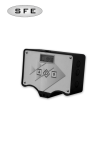
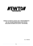
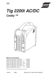
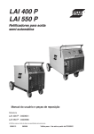
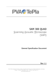
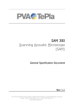
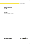
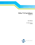
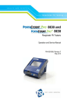
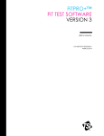
PORTACOUNT® Plus Model 8020 Technical Addendum
revised 7-27-2001
www.tsi.com
PORTACOUNT® Plus Model 8020
Technical Addendum
(includes the N95-Companion™ Model 8095)
TSI Incorporated, St. Paul, Minnesota, USA
Copyright © 2001 all rights reserved
1
PORTACOUNT® Plus Model 8020 Technical Addendum
revised 7-27-2001
INTRODUCTION
This document is a addendum to the PortaCount Plus® Model 8020 Operation
and Service Manual (TSI p/n 1980092). It contains detailed technical information
that is not normally needed by persons using the PortaCount Plus for respirator
fit testing. Persons who will find this document of interest include respirator
manufacturers, respiratory protection researchers, and persons conducting
general ultrafine particle studies not related to respirator fit testing.
The most recent version of this document as well as the PortaCount Plus Model 8020
Operation and Service Manual can be obtained from the TSI Web site www.tsi.com.
CONTENTS
Dip Switch Settings .............................................................. 3
Serial Interface Output ......................................................... 7
Data and Accessory Port Pin Assignments........................ 10
Computer Interface Cables ................................................ 10
Remote Control via Computer............................................ 12
N95-Companion ................................................................. 23
TSI Incorporated, St. Paul, Minnesota, USA
Copyright © 2001 all rights reserved
2
PORTACOUNT® Plus Model 8020 Technical Addendum
revised 7-27-2001
DIP SWITCH SETTINGS
LASER CAUTION
This instrument is a Class I laser device. Adjustments or performance of procedures
other than those specified herein may result in hazardous radiation exposure.
There is a bank of 8 DIP switches located inside the PORTACOUNT Plus. To gain access to
the switches you must separate the top and bottom halves of the enclosure. Follow the
instructions below:
1.
Turn the PORTACOUNT Plus off.
2.
Turn the PORTACOUNT Plus over so that it is face down and locate the four screws
on the bottom that hold the two halves of the enclosure together. Remove all four
screws.
3.
Turn the PORTACOUNT Plus right side up while holding the two halves of the
enclosure together so they do not separate.
4.
Gently lift the top half of the case and set it down just to the left of the unit.
Notice that there is a ribbon cable connecting the top and bottom half together.
Try not to pull on the ribbon cable. You do not need to disconnect the ribbon
cable from the circuit board.
TSI Incorporated, St. Paul, Minnesota, USA
Copyright © 2001 all rights reserved
3
PORTACOUNT® Plus Model 8020 Technical Addendum
revised 7-27-2001
5.
The DIP switches are located
towards the bottom of the circuit board
just to the left of center. Make sure the
PORTACOUNT Plus is always off when
changing DIP switch settings.
There are 8 DIP switches. The top
switch is number 1 and the bottom
switch is number 8. A switch is
considered to be "ON" when the right
side is pushed down and "OFF" when
the left side is down.
As shipped from the factory, the DIP
switches are set as follows:
Switch Number
1
2
3
4
5
6
7
8
Factory Setting
ON
OFF
ON
ON
ON
ON
ON
ON
The function of each of the DIP Switches is as follows. Factory settings are shown in
BOLD type:
DIP Switches 1, 2 and 3: Baud Rate
Switches 1, 2 and 3 control the Baud rate used by the RS-232C Data Port. The factory
setting is for 1200 Baud. If you change the Baud rate of the PORTACOUNT Plus, you must
also change the Baud rate of devices that communicate with the instrument such as a
printer or computer. You should leave the Baud rate set at 1200 unless you have a good
reason to change it. The switch settings for various Baud rates are:
Baud Rate
300
600
1200
2400
9600
Switch 1
ON
OFF
ON
OFF
OFF
Switch 2
ON
ON
OFF
OFF
ON
Switch 3
ON
ON
ON
ON
OFF
All Baud rates use 8 data bits, no parity, 1 stop bit. Switch combinations not shown are
undefined.
TSI Incorporated, St. Paul, Minnesota, USA
Copyright © 2001 all rights reserved
4
PORTACOUNT® Plus Model 8020 Technical Addendum
revised 7-27-2001
DIP Switch 4: Memory Lock
Switch 4 allows you to lock the PORTACOUNT Plus memory so that the internal settings for
the sampling times, fit factor pass level and number of exercises cannot be changed from
the PORTACOUNT Plus Keypad or by using the MODIFY program software supplied with
the instrument. The reason you might want to lock memory is to prevent unauthorized
persons from altering the fit test protocol. The factory setting for switch 4 is ON which
means that memory lock feature is OFF and the internal settings can be changed using the
Keypad or software. The FitPlus software is not affected by DIP switch 4.
Memory
Unlocked
Locked
Switch 4
ON
OFF
DIP Switch 5: Factory Checkout
Switch 5 is used by TSI when performing factory checkout of the PORTACOUNT Plus and
should always be in the ON position for normal use.
Mode
Checkout
Normal
Switch 5
OFF
ON
DIP Switch 6: Reset Factory Settings on Power Up
Switch 6 should always be left ON unless you want to reset all the internal settings back
to the way they were when the PORTACOUNT Plus was new.
When switch 6 is OFF, the PORTACOUNT Plus will reset back to the factory settings when
the power is turned on. Once the power is turned back on, you will be able to change the
internal settings (unless switch 4 is OFF), but they will be reset to the factory values the
next time the power is turned off and then on again.
If you want to reset the internal settings back to the factory values, move switch 6 to the
OFF position and then start the PORTACOUNT Plus. Now turn the PORTACOUNT Plus off and
change switch 6 back to the ON position. The instrument will be reset and you will be
able to permanently change the internal settings. The factory settings are:
Fit Factor Pass Level:
Number of exercises:
Ambient Purge Time
Ambient Sample Time
Mask Purge Time
Mask Sample Time, All exercises:
100
8
4 sec
5 sec
11 sec
40 sec
DIP Switch 7: Reserved
Switch 7 must always be left ON.
DIP Switch 8: Use CTS
When switch 8 is on (the factory setting), the PORTACOUNT Plus will not require a Clear
To Send (CTS) signal in order to send data through the RS-232C Data Port to a
TSI Incorporated, St. Paul, Minnesota, USA
Copyright © 2001 all rights reserved
5
PORTACOUNT® Plus Model 8020 Technical Addendum
revised 7-27-2001
peripheral device. When switch 8 is OFF, the CTS signal will be required. The CTS
signal is always required when the PORTACOUNT Plus is in External Control Mode
regardless of the position of switch 8.
CTS Signal
Not required
Required
Switch 8
ON
OFF
TSI Incorporated, St. Paul, Minnesota, USA
Copyright © 2001 all rights reserved
6
PORTACOUNT® Plus Model 8020 Technical Addendum
revised 7-27-2001
SERIAL INTERFACE OUTPUT
Output in Fit Test Mode
An example of the printout from a eight exercise fit test is shown below. All characters
are ASCII. Each line is terminated with both carriage return (0D hex) and line feed (0A
hex) characters. The comments to the right side do not print.
COMMENTS
NEW TEST PASS = 100Start of new test
Ambient
4750 #/cc
Ambient concentration
Mask
11.30 #/cc
Mask concentration
Ambient
4800 #/cc
Ambient concentration
FF
1
422 PASS
Fit factor exercise 1
Mask
5.20 #/cc
Ambient
4700 #/cc
FF
2
894 PASS
Fit factor exercise 2
Mask
9.80 #/cc
Ambient
5000 #/cc
FF
3
505 PASS
Fit factor exercise 3
Mask
4.10 #/cc
Ambient
5100 #/cc
FF
4
1231 PASS
Fit factor exercise 4
Mask
7.90 #/cc
Ambient
4900 #/cc
FF
5
610 PASS
Fit factor exercise 5
Mask
13.50 #/cc
Ambient
4800 #/cc
FF
6
359 PASS
Fit factor exercise 6
Mask
9.80 #/cc
Ambient
5000 #/cc
FF
7
505 PASS
Fit factor exercise 7
Mask
11.30 #/cc
Ambient
4800 #/cc
FF
8
422 PASS
Fit factor exercise 8
Overall FF 612 PASS
Overall fit factor
Output in Count Mode
The PORTACOUNT Plus sends ASCII characters through the Data Port in the following
format while in 1-Second Count Mode. Each line is terminated with both carriage return
(0D hex) and line feed (0A hex) characters. A line of data is transmitted every 2-seconds
instead of every second to accommodate slow printers. When in 1-Second Count Mode
the Display show 1-second averages updated every second. The Data Port transmits 2second averages updated every 2-seconds.
Conc.
xxxxxx #/cc
TSI Incorporated, St. Paul, Minnesota, USA
Copyright © 2001 all rights reserved
7
PORTACOUNT® Plus Model 8020 Technical Addendum
revised 7-27-2001
In 15-Second Count Mode, the ASCII output is in the following format. Each line is
terminated with both carriage return (0D hex) and line feed (0A hex) characters. A line
of data is transmitted every 15-seconds.
Ave. Conc.
xxxxxx #/cc
The "xxxxxx" is the numeric particle concentration in particles per cubic centimeter.
Concentrations from 100 up to 999999 are formatted as integers, values below 100 have
two decimal places. For example, a concentration of 87 would be transmitted as:
Conc.
87.00 #/cc
Output During the 60-Second Warm-up
During the initial 60-second warm-up period, the PORTACOUNT Plus automatically
transmits status information that shows the internal memory settings. The settings reflect
how the PORTACOUNT Plus memory is set at the moment and can be changed. For
example, when all settings are at the factory settings, the data will transmit as follows:
NOTE:
If the optional Model 8095 N95-Companion is attached and active, the
printout will show the timing used with the N95-Companion. These
settings are different than those used by the PORTACOUNT alone.
PORTACOUNT PLUS PROM Vx.x
COPYRIGHT(c)1991 TSI INC
ALL RIGHTS RESERVED
Serial Number
xxxxx
FF pass level
= 100
No. of exercises = 6
Ambient purge
= 4 sec.
Ambient sample
= 5 sec.
Mask purge
= 11 sec.
Mask sample
1 = 40 sec.
Mask sample
2 = 40 sec.
Mask sample
3 = 40 sec.
Mask sample
4 = 40 sec.
Mask sample
5 = 40 sec.
Mask sample
6 = 40 sec.
Mask sample
7 = 40 sec.
Mask sample
8 = 40 sec.
DIP switch
= 10111111
•
Each line is terminated with both carriage return (0D hex) and line feed (0A hex)
characters.
•
The mask sample times are transmitted only for the number of exercises set.
TSI Incorporated, St. Paul, Minnesota, USA
Copyright © 2001 all rights reserved
8
PORTACOUNT® Plus Model 8020 Technical Addendum
•
revised 7-27-2001
DIP Switches are considered ON if set to 1 and OFF if set to 0. DIP Switches are
numbered 1 - 8 from left to right on the printout and 1 - 8 from top to bottom on the
circuit board.
Output When a Battery Runs Low
The PORTACOUNT Plus will turn itself off when a battery runs out of power. Just before it
turns off the following message is transmitted:
Low Battery
TSI Incorporated, St. Paul, Minnesota, USA
Copyright © 2001 all rights reserved
9
PORTACOUNT® Plus Model 8020 Technical Addendum
revised 7-27-2001
DATA and ACCESSORY PORT PIN ASSIGNMENTS
The PORTACOUNT Plus features bidirectional RS-232C communications
through the Data Port. The Accessory
Port is used to interface with the N95Companion accessory.
ACCY Port
Data Port
The PORTACOUNT Plus Data Port uses a
modular RJ-45 connector with 8
contacts. The contacts are numbered 1
through 8 from left to right when viewed
as shown.
The PORTACOUNT Plus Accessory Port
"ACCY" is a 6-pin MMJ modified
modular connector. Contact 1 is on the left when viewed as shown.
Data Port Pin Assignments
Contact
Number
Function
1
Not used
2
Ready (DTR)
3
Receive data (Rx)
4
Not Used
5
Transmit data (Tx)
6
Not Used
7
Signal Ground (G)
8
Clear to send (CTS)
Direction
From PORTACOUNT Plus
To PORTACOUNT Plus
From PORTACOUNT Plus
To PORTACOUNT Plus
PortaCount Accessory Port Pin Assignments (use TSI cable 1303522)
Contact
Number
Function
Comment
1
Ground (-)
2
+ 5 VDC
Supply voltage for all circuits
except solenoid valve
3
N95 Attach Sense
Pull to ground to signal that
N95-Companion is attached
4
+ 5 VDC Solenoid valve High current supply for
voltage feed
solenoid valve only
5
Solenoid valve control
0.0 VDC = sample from
sample tube
5.0 VDC = sample from
ambient tube
6
Not used
TSI Incorporated, St. Paul, Minnesota, USA
Copyright © 2001 all rights reserved
10
PORTACOUNT® Plus Model 8020 Technical Addendum
revised 7-27-2001
COMPUTER INTERFACE CABLES
The diagrams below show how to connect an IBM-PC compatible RS-232C serial
interface to the PORTACOUNT Plus Data Port. The computer end of these cables are always
female. Serial interface connectors on the back of the computer are always male. Pin 1
on the PORTACOUNT plus Data Port is on the left as you look at the Data Port connector.
The PORTACOUNT Plus Data Port uses a standard RJ-45 Modular Connector.
For 25 pin RS-232 connectors
PORTACOUNT Plus Data Port Pin
1
2
3
4
5
6
7
8
Computer 25 Pin Connector
8
5
2
6
3
22
7
20
For 9 pin RS-232 connectors
PORTACOUNT Plus Data Port Pin
1
2
3
4
5
6
7
8
Computer 9 Pin Connector
1
8
3
6
2
9
5
4
TSI Incorporated, St. Paul, Minnesota, USA
Copyright © 2001 all rights reserved
11
REMOTE CONTROL via COMPUTER
This section describes in detail, how to operate the PORTACOUNT Plus in External Control
Mode through the Data Port. This information will be useful to those who want to write
their own control program.
The following nomenclature is used in this section:
x Single character ASCII numeral (0 - 9)
v Single character ASCII numeral (0 - 9)
<cr>
ASCII carriage return character (OD hex or 13 decimal)
<lf>
ASCII line feed character (OA hex or 10 decimal)
Notes on External Control Mode
•
All characters sent to the PORTACOUNT Plus and all characters returned by the
PORTACOUNT Plus are ASCII.
•
Commands are case sensitive. Be sure to use only uppercase as specified.
•
All commands sent to the PORTACOUNT Plus must be terminated with an ASCII
carriage return <cr> character.
•
All responses returned by the PORTACOUNT Plus will be terminated with both an ASCII
carriage return <cr> and a line feed <lf> character.
•
When the PORTACOUNT Plus receives a command that is not understood or has values
that are outside the allowable range, an ASCII E (for Error) is returned followed by
and echo of the misunderstood command.
For example, if a command is sent to the PORTACOUNT Plus that attempts to change the
ambient purge time to an out of range value such as 3 seconds with the command:
PTPA003<cr>
The PORTACOUNT Plus will respond as follows, without changing the ambient
purge time:
EPTPA003<cr><lf>
•
When the PORTACOUNT Plus receives a command that attempts to alter a setting that is
locked because DIP switch 4 is OFF, it will return an ASCII W (for Write protected)
followed by an echo of the illegal command. See the Appendix on DIP switch
settings for details on locking memory with DIP switch 4.
For example, if DIP switch 4 is OFF and an attempt is made to change the mask
sample time for exercise 3 to 30 seconds with the command:
PORTACOUNT® Plus Model 8020 Technical Addendum
revised 7-27-2001
PTM0330<cr>
The PORTACOUNT Plus will respond as follows, without changing the mask sample
time:
WPTM0330<cr><lf>
•
If a low battery condition occurs while the PORTACOUNT Plus is in External Control
Mode, the following characters are transmitted just before the unit turns itself off:
Low Battery<cr><lf>
The following table describes each of the available external commands and responses in
detail.
COMMAND
J<cr>
DESCRIPTION
Invoke External Control
This command puts the PORTACOUNT Plus into External Control Mode. All
characters sent are ignored until the first J<cr> is received.
Response from PORTACOUNT Plus:
OK<cr><lf>
When External Control Mode is invoked, certain parameters are automatically set as
follows:
•
•
•
•
•
G<cr>
The internal valve is set to OFF. This position forces air to be drawn through the
Sample Tube.
The PORTACOUNT Plus Display is cleared.
The External Control indicator on the Keypad is turned ON.
Count Mode and Fit Test Mode indicators are turned OFF.
Continuous transmission of concentration data is enabled as if the ZE<cr>
command had been received.
Release from External Control
This command puts the PORTACOUNT Plus back into Local Mode so it can be
operated from the keypad.
Response from PORTACOUNT Plus:
G<cr><lf>
Q<cr>
Test to see if N95-Companion is attached
QN<cr><lf> (Response if N95-Companion IS NOT attached)
QY<cr><lf> Response if N95-Companion IS attached:
TSI Incorporated, St. Paul, Minnesota, USA
Copyright © 2001 all rights reserved
13
PORTACOUNT® Plus Model 8020 Technical Addendum
COMMAND
VN<cr>
revised 7-27-2001
DESCRIPTION
Switch Valve ON (sample through Ambient Tube)
This command switches the internal valve to the ON position which forces the
sampled air to be drawn through the Ambient Tube. The valve is automatically set to
OFF when the External Control Mode is first invoked.
Response from PORTACOUNT Plus:
VN<cr><lf>
VF<cr>
Switch Valve OFF (sample through Sample Tube)
This command switches the internal valve to the OFF position which forces the
sampled air to be drawn through the Sample Tube. The valve is automatically set to
OFF when External Control Mode is first invoked.
Response from PORTACOUNT Plus:
VO<cr><lf>
ZD<cr>
Disable Continuous Data Transmission
This command tells the PORTACOUNT Plus to stop sending continuous particle
concentration data.
Response from PORTACOUNT Plus:
ZD<cr><lf>
ZE<cr>
Enable Continuous Data Transmission
This command tells the PORTACOUNT Plus to continuously transmit particle
concentration data in 1-second intervals.
Response from PORTACOUNT Plus is to echo:
ZE<cr><lf>
and then begin sending concentration data in units of particles per cubic centimeter.
The data values are in the format:
xxxxxx.xx<cr><lf>
All values are right justified with leading zeros as needed to send 9 characters
including the decimal point.
Example:
Concentration
Particles/cm3
0.60
100
4756.5
23941
496720
Transmitted
Characters
000000.60<cr><lf>
000100.00<cr><lf>
004756.50<cr><lf>
023941.00<cr><lf>
496720.00<cr><lf>
TSI Incorporated, St. Paul, Minnesota, USA
Copyright © 2001 all rights reserved
14
PORTACOUNT® Plus Model 8020 Technical Addendum
COMMAND
R<cr>
revised 7-27-2001
DESCRIPTION
Request Runtime Status of Battery and Signal Pulse
This command forces the PORTACOUNT Plus to report the battery condition and the
sensor pulse condition. Three characters are returned by the PORTACOUNT Plus.
The first character is always an R. The second character is the battery condition and
the third is the sensor pulse condition. When the AC Adapter is in use, the first
character indicates the condition of the power supply voltage rather than a battery.
Possible responses from PORTACOUNT Plus
S<cr>
RGG<cr><lf>
Battery Good, Pulse Good
RGB<cr><lf>
Battery Good, Pulse Bad
RBG<cr><lf>
Battery Bad, Pulse Good
RBB<cr><lf>
Battery Bad, Pulse Bad
Request Settings
This command forces the PORTACOUNT Plus to transmit all current settings for
sample times, fit factor pass level, serial number, Hours of operation and date last
serviced. Each item is described below in the order it is transmitted.
Ambient Purge Time
STPA 000vv<cr><lf>
vv is the ambient purge time in seconds. The value will be in the range from 04 to
25. All exercises use the same ambient purge time.
Ambient Sample Time
STA
000vv<cr><lf>
vv is the ambient sample time in seconds. The value will be in the range from 05 to
99. All exercises use the same ambient sample time. There are 2 spaced after the
STA.
Mask Sample Purge Time
STPM 000vv<cr><lf>
vv is the mask sample purge time in seconds. The value will be in the range from 11
to 99. All exercises use the same mask sample purge time. There is one space after
the STPM.
Mask Sample Times
STMxx000vv<cr><lf>
(continued on next page)
TSI Incorporated, St. Paul, Minnesota, USA
Copyright © 2001 all rights reserved
15
PORTACOUNT® Plus Model 8020 Technical Addendum
COMMAND
S<cr>
(continued)
revised 7-27-2001
DESCRIPTION
(continued from previous page)
13 lines will be transmitted, one for each exercise. xx is the exercise number (01 to
13) and vv is the mask sample time in seconds. Mask sample times will be in the
range from 10 to 99 seconds. The 13th line is the mask sample time (60 seconds)
used when the number of exercises is set to zero (8010 Mode). The 13th mask sample
time cannot be changed.
Fit Factor Pass Levels
SP xxvvvvv<cr><lf>
12 lines will be transmitted, one for each of the fit factor pass levels stored in
memory. The PORTACOUNT Plus stores 12 fit factor pass levels in memory and
allows an operator to scroll through the list using the Keypad. Xx is the memory
location between 01 and 12. Vvvvv is the fit factor pass level contained in that
memory location. The maximum value allowed for the fit factor pass level is 64000.
There is one space after the SP.
Serial Number
The PORTACOUNT Plus serial number is transmitted in the format:
SS
vvvvv<cr><lf>
vvvvv is the serial number. There are three spaces after the SS.
Run Time Since Last Serviced at the Factory
The run time since the last time factory service was provided is transmitted in the
format:
SR
vvvvv<cr><lf>
vvvvv is the run time in 10 minute increments. There are three spaces after the SR.
For example:
SR
05370<cr><lf>
indicates that the unit has run for 53700 minutes or 895 hours since last serviced.
The timer is reset at the factory when service is performed.
Date Last Serviced
The date when the PORTACOUNT Plus was last serviced at the factory is
transmitted in the format:
SD
0MMYY<cr><lf>
Where MM is the month number (01 to 12) and YY is the last 2 digits of the year (91
= 1991, 93 = 1993, 00 = 2000 etc.). The character before the month number (MM)
is always a zero. There are three spaces after the SD.
TSI Incorporated, St. Paul, Minnesota, USA
Copyright © 2001 all rights reserved
16
PORTACOUNT® Plus Model 8020 Technical Addendum
COMMAND
Y<cr>
revised 7-27-2001
DESCRIPTION
Turn Power OFF
This command turns the PORTACOUNT Plus OFF. It must be turned ON using the
Keypad. There is no way to turn the PORTACOUNT Plus ON using an external
computer. When first turned ON the PORTACOUNT Plus is always operable using
the Keypad.
Response from PORTACOUNT Plus just before it turns off:
Y<cr><lf>
PTMxxvv<cr>
Set Mask Sample Time
Each exercise has its own independent mask sample time. xx is the exercise number
between 01 and 12. vv is the mask sample time in seconds between 10 and 99.
For example, to set the mask sample time for exercise 4 to 40 seconds, send the
command:
PTM0440<cr>
The PORTACOUNT Plus will respond with an echo of the same command:
PTM0440<cr><lf>
PTA00vv<cr>
Set Ambient Sample Time
This command sets the ambient sample time for exercises 1 through 12. vv is the
ambient sample time in seconds and must be in the range from 05 to 99.
For example, to set the ambient sample time to 10 seconds, send the command:
PTA0010<cr>
The PORTACOUNT Plus will respond with an echo of the same command:
PTA0010<cr><lf>
PTPM0vv<cr>
Set Mask Sample Purge Time
This command sets the mask sample purge time for exercises 1 through 12. vv is the
mask sample purge time in seconds and must be in the range from 11 to 25.
For example, to set the mask sample purge time to 15 seconds, send the command:
PTPM015<cr>
The PORTACOUNT Plus will respond with an echo of the same command:
PTPM015<cr><lf>
TSI Incorporated, St. Paul, Minnesota, USA
Copyright © 2001 all rights reserved
17
PORTACOUNT® Plus Model 8020 Technical Addendum
COMMAND
PTPA0vv<cr>
revised 7-27-2001
DESCRIPTION
Set Ambient Sample Purge Time
This command sets the ambient sample purge time for exercises 1 through 12. vv is
the ambient sample purge time in seconds and must be in the range from 04 to 25.
For example, to set the ambient sample purge time to 8 seconds, send the command:
PTPA008<cr>
The PORTACOUNT Plus will respond with an echo of the same command:
PTPA008<cr><lf>
PPxxvvvvv<c
r>
Set Fit Factor Pass Level
The PORTACOUNT Plus stores a set of 12 fit factor pass levels in memory. The
operator is allowed to scroll through and select one of
these values as the current fit factor pass level using the PORTACOUNT Plus
Keypad.
This command allows any of the 12 fit factor pass levels stored in the
PORTACOUNT Plus to be permanently changed. xx is the memory location from
01 to 12. vvvvv is the new fit factor pass level between 00000 and 64000. All fit
factor pass levels must have 5 characters. Use leading zeros when necessary, such as
000350 for 350 and 02000 for 2000.
For example, to change the 3rd of 12 fit factor pass levels to 350, send the command:
PP0300350<cr>
The PORTACOUNT Plus will respond with an echo of the same command:
PP0300350<cr><lf>
TSI Incorporated, St. Paul, Minnesota, USA
Copyright © 2001 all rights reserved
18
PORTACOUNT® Plus Model 8020 Technical Addendum
COMMAND
Dxxxxxx.xx<cr>
revised 7-27-2001
DESCRIPTION
Display Concentration on PORTACOUNT Plus
This command clears the entire Display and then displays a concentration value.
The PARTICLE/cm3 message is turned ON. xxxxxx.xx is the concentration
to display and can be any number from 000000.00 to 999999.99. The
concentration value must be 9 characters long including the decimal point so add
zeros as needed on the left. Characters to the right of the decimal point are not
displayed if the value to the left of the decimal point is above 100, however, they
must be included in this command even if they are both zeros.
For example, to display a concentration of 5375 send the command:
D005375.00<cr>
The PORTACOUNT Plus responds by echoing:
D005375.00<cr><lf>
Lxxxxxx<cr>
Display Fit Factor Pass Level on PORTACOUNT Plus
This command clears the Display and then displays a fit factor pass level. The
FIT FACTOR PASS LEVEL message is turned ON. xxxxxx is the fit factor
pass level to display and can be in the range from 000000 to 999999. The
value to display must have 6 characters so add zeros on the left as needed.
For example, to display a fit factor pass level of 1000, send the command:
L001000<cr>
The PORTACOUNT Plus responds by echoing:
L001000<cr><lf>
Fxxxxxx.x<cr>
Display Fit Factor on PORTACOUNT Plus
This command clears the entire Display and then displays a fit factor value. The
FIT FACTOR message is turned ON. xxxxxx.x is the fit factor to display and
can be any number from 000000.0 to 999999.9. The fit factor value must
be 8 characters long including the decimal point so add zeros as needed on the
left. The character to the right of the decimal point is not displayed if the value
to the left of the decimal point is above 10, however, it must be included in this
command even if it is zero.
For example, to display a fit factor of 6240 send the command:
F006240.0<cr>
The PORTACOUNT Plus responds by echoing:
F006240.0<cr><lf>
TSI Incorporated, St. Paul, Minnesota, USA
Copyright © 2001 all rights reserved
19
PORTACOUNT® Plus Model 8020 Technical Addendum
COMMAND
Axxxxxx.x<cr>
revised 7-27-2001
DESCRIPTION
Display Overall Fit Factor on PORTACOUNT Plus
This command clears the entire Display and then displays an overall fit factor
value. The OVERALL FIT FACTOR message is turned ON. xxxxxx.x is the
overall fit factor to display and can be any number from 000000.0 to
999999.9. The overall fit factor value must be 8 characters long including the
decimal point so add zeros as needed on the left. The character to the right of the
decimal point is not displayed if the value to the left of the decimal point is above
10, however, it must be included in this command even if it is zero.
For example, to display an overall fit factor of 740 send the command:
A000740.0<cr>
The PORTACOUNT Plus responds by echoing:
A000740.0<cr><lf>
Nxx<cr>
Display Exercise Number on PORTACOUNT Plus
This command displays an exercise number on the PORTACOUNT Plus
Display. xx is the number to display and must be in the range from 00 to 19.
For example, to display the exercise number 5 on the PORTACOUNT Plus send
the command:
N05<cr>
The PORTACOUNT Plus will respond with an echo of the same command:
N05<cr><lf>
Ixxxxxxxx<cr>
Display Indicator Message on PORTACOUNT Plus
This command causes selected indicator messages to turn ON or OFF on the
PORTACOUNT Plus Display. xxxxxxxx represents an eight-place binary value.
Each bit corresponds to a particular indicator message. 1 means ON and 0 means
OFF. The left most bit is bit 1 and the bit furthest to the right is bit 8. Each of
the 8 bits controls a certain indicator message as described below.
Bit 1: Not Used
Bit one is not used and is ignored by the PORTACOUNT Plus. For simplicity, a
zero (0) will always be used for bit 1.
Bit 2: IN PROGRESS Message
1 = Turn IN PROGRESS message ON (it will flash)
0 = Turn IN PROGRESS message OFF
(continued on next page)
TSI Incorporated, St. Paul, Minnesota, USA
Copyright © 2001 all rights reserved
20
PORTACOUNT® Plus Model 8020 Technical Addendum
COMMAND
Ixxxxxxxx<cr>
(continued)
revised 7-27-2001
DESCRIPTION
(continued from previous page)
Bit 3: FIT FACTOR Message
1 = Turn FIT FACTOR message ON
0 = Turn FIT FACTOR message OFF
Bit 4: SERVICE Message
1 = Turn SERVICE message ON
0 = Turn SERVICE message OFF
Bit 5: LOW PARTICLE Message
1 = Turn LOW PARTICLE message ON
0 = Turn LOW PARTICLE message OFF
Bit 6: LOW BATTERY Message
1 = Turn LOW BATTERY message ON
0 = Turn LOW BATTERY message OFF
The LOW BATTERY message will flash when it is ON.
Bit 7: FAIL Message
1 = Turn FAIL message ON
0 = Turn FAIL message OFF
Bit 8: PASS Message
1 = Turn PASS message ON
0 = Turn PASS message OFF
For example, to turn all messages OFF, all bits would be zero so send the
command:
I00000000<cr>
The PORTACOUNT Plus will respond:
I00000000<cr><lf>
(continued on next page)
TSI Incorporated, St. Paul, Minnesota, USA
Copyright © 2001 all rights reserved
21
PORTACOUNT® Plus Model 8020 Technical Addendum
COMMAND
Ixxxxxxxx<cr>
(continued)
revised 7-27-2001
DESCRIPTION
(continued from previous page)
To turn the FAIL message on only, bit 7 must be a 1, send the command:
I00000010<cr>
The PORTACOUNT Plus will respond:
(continued on next page)
(continued from previous page)
I00000010<cr><lf>
To turn the FAIL message OFF and the PASS message ON with one command,
bit 7 must be a zero and bit 8 must be a 1, send:
I00000001<cr>
The PORTACOUNT Plus responds:
I00000001<cr><lf>
To turn the FIT FACTOR message and the PASS message ON at the same time
bit 3 must be a 1 and bit 8 must be a 1, send:
I00100001<cr>
The PORTACOUNT Plus responds:
I00100001<cr><lf>
K<cr>
Clear Display on PORTACOUNT Plus
This command clears the entire PORTACOUNT Plus Display. Send the
command:
Response from PORTACOUNT Plus:
K<cr><lf>
Bxx<cr>
Sound Beeper inside the PORTACOUNT Plus
This command causes the internal beeper to sound. Xx is the duration of the
beep in 1/10 seconds in the range from 01 to 99 (0.1 to 9.9 seconds).
For example, to sound a 5/10 ( = 1/2 ) second beep, send the command:
B05<cr>
The PORTACOUNT Plus beeps for the specified time interval and responds:
B05<cr><lf>
TSI Incorporated, St. Paul, Minnesota, USA
Copyright © 2001 all rights reserved
22
PORTACOUNT® Plus Model 8020 Technical Addendum
revised 7-27-2001
N95-Companion Model 8095
The N95-Companion is an accessory for the
PortaCount Plus that permits the PortaCount to
perform quantitative fit testing on low efficiency
disposable respirators such as class-95 (USA) and
class-P1/P2 (other countries). The N95Companion is essentially an electrostatic particle
classifier (a.k.a. Differential Mobility Analyzer or
DMA) that strips off all particle sizes above and
below the target particle size of approximately
0.04 micrometers. The target particle size is
fixed and cannot be adjusted. Refer to the N95Companion Operation and Service Manual (TSI
part no. 1980308) for operation and maintenance
instruction. Visit www.tsi.com to obtain a copy.
To operate with the N95-Companion the
PortaCount Plus must have the revision A
modifications. The tag on the bottom of the
PortaCount Plus will show MODEL 8020A if it
is "N95-Companion ready." Revision A
modifications can be added to older PortaCounts
via factory service.
Sampling Pendant
N95-Companion Theory of Operation
The fundamental assumption made when fit testing with the PortaCount is that any
particles sampled from inside the respirator must have entered through a leak since they
cannot pass through the filter. This assumption is always true for high efficiency filters,
but fails for low efficiency filters. There are enough particle passing through low
efficiency media to bias the fit test and cause very low fit factors even when the face seal
is perfect. The PortaCount does not know the difference between a particle that entered
via a face seal leak and one that passed through the filter media.
Ambient
Sample
VALVE
N95-COMPANION
PORTACOUNT
Mask
Sample
Exhaust
TSI Incorporated, St. Paul, Minnesota, USA
Copyright © 2001 all rights reserved
23
PORTACOUNT® Plus Model 8020 Technical Addendum
revised 7-27-2001
The N95-Companion is used as a particle conditioner in between the respirator and the
PortaCount. The 0.04 micrometer particles that are allowed to pass through to the
PortaCount are in the size range that is effectively stopped by low efficiency filter media
as well as high efficiency media. By only allowing the PortaCount to "see" particles that
can only enter the respirator via a face seal leak, the N95-Companion makes low
efficiency media look like high efficiency media to the PortaCount. Since both the
ambient and respirator sample pass through the N95-Companion, the ratio of outside
concentration vs. inside concentration (fit factor) is valid.
For more information visit the www.tsi.com and review the following documents:
Mechanisms of Filtration for High Efficiency Fibrous Filters (Application Note ITI-041)
PortaCount Theory of Operation (Application Note ITI-048)
N95-Companion Model 8095 Theory of Operation (Application Note ITI-053)
Penetration of Ambient Aerosols Through Respirator Faceseal Leaks (Application Note ITI-055)
Fit Testing Using Size-Selected Aerosol (Application Note ITI-062)
PortaCount Internal Program Configuration
When the PortaCount Plus senses the presence of the N95-Companion it automatically
resets itself and runs with special configuration parameters designed to function with the
N95-Companion. The changes include:
•
Sample timing changes to accommodate the longer N95-Companion sampling
requirements.
Ambient purge = 6 seconds
Ambient sample = 15 sec
Mask purge = 15 sec
Mask sample 50 sec,
•
The maximum fit factor that can be displayed is 200. Any fit factor measured to be
above 200 is displayed as 200 with the words "Fit Factor" flashing. The 200 limit
was necessary because the particle concentrations output by the N95-Companion are
too low to allow accurate fit factor measurements at higher levels.
•
The pump inside the N95-Companion runs in addition to the pump inside the
PortaCount.
TSI Incorporated, St. Paul, Minnesota, USA
Copyright © 2001 all rights reserved
24
PORTACOUNT® Plus Model 8020 Technical Addendum
revised 7-27-2001
•
The valve inside the PortaCount is no longer used and is left un-energized (sample
tube open). The valve control is automatically re-routed to the N-95-Companion
valve located inside the Sampling Pendant.
•
The minimum ambient particle concentration necessary to allow a fit test drops from
1000 to 70 particles/cm3.
TSI Incorporated, St. Paul, Minnesota, USA
Copyright © 2001 all rights reserved
25
PORTACOUNT® Plus Model 8020 Technical Addendum
•
revised 7-27-2001
The internal pass/fail settings are reduced by a factor of 10.
Pass/Fail setting
for PortaCount
alone
0
1 to 10*
50*
100
200
500
1000
2000 or higher
Pass/Fail setting
with N95-Companion
0
1
5
10
20
50
100
200
Comment
Pass/Fail indicator OFF
Minimum pass/fail = 1
Maximum pass/fail =
200
* Not a factory setting
N95-Companion Front Panel
Sample inlet
3
(approx. 700 cm /min)
Sample outlet
(to PortaCount)
Pendant valve control
connector
TSI Incorporated, St. Paul, Minnesota, USA
Copyright © 2001 all rights reserved
26
PORTACOUNT® Plus Model 8020 Technical Addendum
revised 7-27-2001
N95-Companion Sampling Pendant
+ 5 VDC
(to hold valve
open on ambient
sample tube)
Ground (-)
Pendant valve control
connector
(from N95-Companion)
Sample outlet
(to N95-Companion)
N95-Companion Back Panel
Particle Classifier
Check Button
(turns DMA off)
Factory use only
N95-Companion Control Connector
Contact
Number Function
1
Ground (-)
2
+ 5 VDC (from PortaCount)
3
4
5
6
Control Connector
(6-pin MMJ to PortaCount)
Use TSI cable 1303522
Comment
Supply voltage for all circuits
except solenoid valve in
pendant
N95 Attach Signal
Jumpered to ground to signal
(to PortaCount)
PortaCount that N95Companion is attached
+ 5 VDC Solenoid valve
High current voltage supply
voltage feed (from PortaCount) for solenoid valve in pendant
Solenoid valve control
0.0 VDC = sample from
(from PortaCount)
sample tube (normal position)
5.0 VDC = sample from
ambient tube (maintain voltage
while sampling)
Not used
TSI Incorporated, St. Paul, Minnesota, USA
Copyright © 2001 all rights reserved
27
PORTACOUNT® Plus Model 8020 Technical Addendum
TSI Incorporated, St. Paul, Minnesota, USA
Copyright © 2001 all rights reserved
revised 7-27-2001
28