1
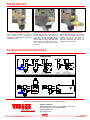
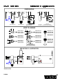
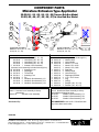
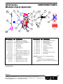
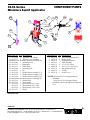
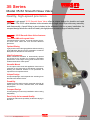
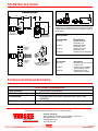
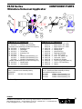
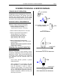
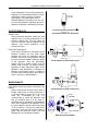
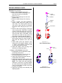
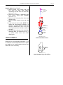
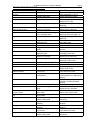
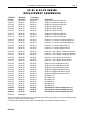
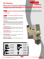
35 Series
Gluing Systems
Model 35-51 Miniature Applicators
A Valco Cincinnati Company
Change-up, quick and easy.
’s 35-51 Series Miniature Applicators offer quick and easy solutions to simplify a number of
industry requirements. This compact and advanced design is proven to optimize production without
a lot of downtime.
’s 35-51 Miniature Applicators features:
Speed
A diaphragm suspended actuating lever arm and construction
is used to eliminate friction for fast, repeatable action. It can be
used in low to very high speed applications.
Durability
A hardened valve needle and seat are used for extended valve
life. A solid brass body with stainless-steel, nylon, UHMWPE,
and Teflon® parts stand up better against rugged use. It is
capable of 100 million cycles before replacement of internal
parts.
Low Maintenance
A sealed tip reduces the possibility of adhesive drying in the
valve. All component parts are easily accessible by removing
two plugs and four screws.
Compact Design
A small package is used for easy installation and simple
mounting in small spaces.
Unique Design
A unique diaphragm seal suspends the actuating lever,
reducing friction created during actuation.
Applicator Variety
Three types of Applicator Valves are available. See the back
page for more information.
How to order:
.500”
.500”
.250”
.620” .250”
.620” .310”
35-51-10 L/V
35-51-11 S/V
35-51-12 H/V
.310”
35-51-35 L/V
35-51-36 S/V
35-51-37 H/V
35-51-20 L/V
35-51-21 S/V
35-51-22 H/V
35-52-00 L/V
35-52-01 S/V
35-52-02 H/V
35-51-25 L/V
35-51-26 S/V
35-51-27 H/V
35-51-55 L/V
35-51-56 S/V
35-51-57 H/V
MINI-SQUIRT
35-51-30 L/V
35-51-31 S/V
35-51-32 H/V
© Valco Cincinnati, Inc. All Rights Reserved.
35-51-60 L/V
35-51-61 S/V
35-51-62 H/V
MINI-SPRAY
KCG VCL011 EN 001 MMM
Please Recycle
35-51 Series
Squirt Applicator Valves
Extrusion Applicator Valves
Spray Applicator Valves
Used to squirt adhesive on a product
under pressure. The adhesive is
deposited in a single stream. No product
contact is required.
Used to apply fine lines of adhesive on a
product. Available for in-line sheet fed
and in-line web fed mounting. Single
outlet valves are also available for right
angle actuator mounting. The dual outlet
valves come with a choice of a 0.250” or
0.312” orifice spring. No product contact
is required.
Used to spray the adhesive on a product.
This is particularly useful when a thin
adhesive film or fast tack time are
required. Atomizing air control is
provided to adjust the spray pattern. No
product contact is required.
Technical Characteristics
DIMENSIONS
.750”
1.250”
.910”
.750”
.375”
.910”
.500”
.500”
.375”
.910”
*
.375”
.460” 1.270”
.820”
.460”
1.870”
1.390”
SPRAY APPLICATOR
SQUIRT APPLICATOR
END VIEW
SPRAY APPLICATOR
SQUIRT APPLICATOR
END VIEW
EXTRUSION APPLICATOR
EXTRUSION
APPLICATOR *SEE BELOW FOR WIDTH DIMENSION
MOUNTING ILLUSTRATION
For more information visit www.vansco.com or contact us direct.
Gluing Systems
A Valco Cincinnati Company
© Valco Cincinnati, Inc. All Rights Reserved.
VanSco Products
2652 Lashbrook Avenue, South El Monte, CA 91733
Tel: 626.448.7611 / Fax: 626.448.0221
[email protected]
www.vansco.com
Please Recycle
DIMENSIONS
.7 50”
1 .250”
.9 10”
.3 75”
.7 50”
.9 10”
.5 00”
.5 00”
.3 75”
.9 10”
*
.3 75”
.4 60” 1 .270”
.8 20”
.4 60”
1 .870”
1 .390”
S PRAY A P PL ICATO R
S QU IR T A PP LIC ATO R
E ND VIE W
S PRAY A P PL ICATO R
S QU IR T A PP LIC ATO R
E ND VIE W
E XTR U SIO N AP PL IC ATO R
E XTR U SIO N
A PPL IC ATOR *SE E B EL O W FO R WIDTH D IM E NS ION
HO W TO OR DER
.5 0 0 ”
.5 0 0 ”
35-51-10 L/V
35-51-11 S/V
35-51-12 H/V
.2 5 0 ”
35-51-20 L/V
35-51-21 S/V
35-51-22 H/V
.6 2 0 ” .2 5 0 ”
35-51-25 L/V
35-51-26 S/V
35-51-27 H/V
.6 2 0 ” .3 1 0 ”
35-51-30 L/V
35-51-31 S/V
35-51-32 H/V
.3 1 0 ”
35-51-35 L/V
35-51-36 S/V
35-51-37 H/V
35-52-00 L/V
35-52-01 S/V
35-52-02 H/V
35-52 SERIES
(SEE B ROCHU R E DAN
FOR FURTH ER D ETAILS)
M O U N TIN G ILLU STR ATIO N
Distributed By:
DAK699
35-51-55 L/V
35-51-56 S/V
35-51-57 H/V
MINI-SQUIRT
35-51-60 L/V
35-51-61 S/V
35-51-62 H/V
MINI-SPRAY
COMPONENT PARTS
Miniature Extrusion Type Applicator
35-51(-20, -21, -22, -30, -31, -32) Travers Rub Bar Model
35-51(-25, -26, -27, -35, -36, -37) In Line Rub Bar Model
3a
3b
6
1
3
2
2d
2b
2a
5
3c
4
7 2e 2c
11
TRAVERSE RUB BAR
MODELS: 35-51(-20, -21, -22),
35-51(-30, -31, -32)
10
ITEM PART NO. QTY DESCRIPTION
1
90-35-43 1 Valve Body (-20, -21, -22)
90-35-44 1 Valve Body (-25, -26, -27)
90-35-45 1 Valve Body (-30, -31, -32)
90-35-46 1 Valve Body (-35, -36, -37)
2 90-35-35 1 Actuator Lever Assembly
(Actuator Lever Assembly includes 2a through 2e)
2a 90-35-08 1 Actuating Lever
2b 90-35-32 1 Diaphragm
2c 90-35-15 1 Thrust Plate
2d 90-35-11 1 Actuating Fork
2e 90-35-23 2 Pin
3 90-35-38 2 Needle & Seat Assembly, L/V
90-35-26 2 Needle & Seat Assembly, S/V
90-35-39 2 Needle & Seat Assembly, H/V
ACTUATOR LEVER ASSEMBLY SERVICE KIT
Item 2: Actuator Lever Assembly is factory
assembled.
90-35-35
Actuator Lever Assembly
Distributed By:
9
8
12
IN LINE RUB BAR
MODELS: 35-51(-25, -26, -27),
35-51(-35, -36, -37)
ITEM PART NO. QTY DESCRIPTION
(Needle & Seat Assembly includes 3a through 3c)
3a 90-35-19 1 Needle Head
3b 90-35-20 1 Valve Needle
3c 90-35-36 1 Nozzle, L/V, 0.010
90-35-12 1 Nozzle, S/V, 0.020
90-35-37 1 Nozzle, H/V, 0.030
4 90-35-17 8 Seat Seal
5 90-35-14 3 Needle Guide
6 90-35-13 2 Valve End Plug
7 90-35-30 1 Diaphragm Retainer
8 90-07-12 4 1-72 x 3/16" Screw
9 90-35-31 1 Plug
10 90-07-01 1 O-Ring
11 90-35-21 1 Rub Bar (-00, -01, -02)
12 90-35-22 3 Rub Bar (-05, -06, -07)
NEEDLE & SEAT ASSEMBLY SERVICE KITS
Item 3: Needle and Seat Assembly is factory
assembled and lapped as a set.
90-35-38
Needle & Seat Assembly, L/V
90-35-26
Needle & Seat Assembly, S/V
90-35-39
Needle & Seat Assembly, H/V
RECOMMENDED: Use 90-35-17 Seat Seal with
any of the above service kits.
DAS1299
VanSco Products-The Gluing Equipment Innovators
2652 Lashbrook Avenue • South El Monte, CA 91733 • 626-448-7611 • Fax 626-448-0221
E-mail: [email protected] • URL: www.vansco.com
35-51 Series
Miniature Spray Applicator
3a
14
COMPONENT PARTS
7
1
2b
2d
2a
5
3
6 2e
3b
8
2c
11
10
13
3c
2
4
9
12
ITEM PART NO. QTY DESCRIPTION
1 90-35-49 1 Applicator Valve Body
*2 90-35-33 1 Actuator Lever Assembly
(Actuator Lever Assembly includes 2a through 2e)
2a 90-35-08 1 Actuating Lever
2b 90-35-32 1 Diaphragm
2c 90-35-15 1 Thrust Plate
2d 90-35-09 1 Actuating Fork
2e 90-35-23 1 Pin
*3 90-35-61 1 Needle & Seat Assembly, L/V
90-35-62 1 Needle & Seat Assembly, S/V
90-35-63 1 Needle & Seat Assembly, H/V
(Needle & Seat Assembly includes 3a through 3c)
3a 90-35-19 1 Needle Head
3b 90-35-52 1 Valve Needle
3c 90-35-53 1 Spray Nozzle, L/V, 0.010
90-35-54 1 Spray Nozzle, S/V, 0.020
90-35-55 1 Spray Nozzle, H/V, 0.030
ITEM PART NO. QTY DESCRIPTION
4
5
6
7
8
9
10
11
12
13
14
90-35-59
90-35-14
90-35-30
90-35-13
90-07-12
90-02-33
90-35-31
90-07-01
90-35-60
90-35-67
90-06-98
1
2
1
1
4
1
1
1
1
1
1
Air Nozzle Retaining Nut
Needle Guide
Diaphragm Retainer
Valve End Plug
1-72 x 3/16" Screw
O-Ring
Plug (Shipped Loose)
O-Ring
Air Nozzle
Atomizing Air Adj. Valve
Hose Barb
*NOTE: Item 2 (90-35-33) is shipped factory
assembled.
Item 3 (90-35-26) is shipped factory
assembled with Needle and Nozzle lapped as
a set.
Distributed By:
DAO1199
VanSco Products-The Gluing Equipment Innovators
2652 Lashbrook Avenue • South El Monte, CA 91733 • 626-448-7611 • Fax 626-448-0221
E-mail: [email protected] • URL: www.vansco.com
35-51 Series
Miniature Squirt Applicator
COMPONENT PARTS
1
3a
2
2b
2d
2a
5
3
6 2e
3b
3d
8
2c
11
10
9
4
3c
12
ITEM PART NO. QTY DESCRIPTION
1 90-35-49 1 Applicator Valve Body
*2 90-35-33 1 Actuator Lever Assembly
(Actuator Lever Assembly includes 2a through 2e)
2a 90-35-08 1 Actuating Lever
2b 90-35-32 1 Diaphragm
2c 90-35-15 1 Thrust Plate
2d 90-35-09 1 Actuating Fork
2e 90-35-23 1 Pin
*3 90-35-64 1 Needle & Seat Assembly, L/V
*3 90-35-65 1 Needle & Seat Assembly, S/V
*3 90-35-66 1 Needle & Seat Assembly, H/V
(Needle & Seat Assembly includes 3a through 3d)
3a 90-35-19 1 Needle Head
3b 90-35-52 1 Valve Needle
3c 90-35-56 1 Squirt Nozzle, L/V, 0.010
90-35-57 1 Squirt Nozzle, S/V, 0.020
90-35-58 1 Squirt Nozzle, H/V, 0.030
3d 90-35-71 1 Gasket
ITEM PART NO. QTY DESCRIPTION
4
5
6
7
8
9
10
11
12
90-35-59
90-35-14
90-35-30
90-35-13
90-07-12
90-02-49
90-35-31
90-07-01
90-35-70
1
2
1
1
4
1
1
1
1
Air Nozzle Retaining Nut
Needle Guide
Diaphragm Retainer
Valve End Plug
1-72 x 3/16" Screw
10-32 x 3/16" Set Screw
Plug (Shipped Loose)
O-Ring
Nozzle Cover
*NOTE: Item 2 (90-35-33) is shipped factory
assembled.
Item 3 (90-35-26) is shipped factory
assembled with Needle and Nozzle lapped as
a set.
Distributed By:
DAO1199
VanSco Products-The Gluing Equipment Innovators
2652 Lashbrook Avenue • South El Monte, CA 91733 • 626-448-7611 • Fax 626-448-0221
E-mail: [email protected] • URL: www.vansco.com
35 Series
Model 35-52 Smooth Nose Valve
Gluing Systems
A Valco Cincinnati Company
Quality, high-speed precision.
’s high-speed 35-52 Smooth Nose Valve offers a unique design for durable and rapid
placement. The 32-52 valve attaches to the actuator with a single screw to provide easy assembly
and disassembly. A push fitting is also included at the adhesive inlet for an easy installation. Its
compact design allows the valve to fit easily into tight places to meet a range of industry needs.
’s 35-52 Smooth Nose Valve features:
Fastest and Most Accurate Valve
Combined with the VanSco® 40-40-02 Actuator, the 3552 series valve offers fast and accurate adhesive
placement.
Optimal Gluing
Light product contact during application allows smearing
of the adhesive directly onto the substrate to maximize
absorption into the fiber for a secure bond.
High Performance
Direct mechanical actuation is automatically opened
and closed by the actuator for consistent, repeatable
performance. Low weight moving parts minimize valve
inertia and maximize valve speed.
Versatile Mount
The one-piece valve seat and application head can be
mounted on the valve body at 90-degree increments,
allowing the attached actuator to be positioned as
required for in-line product travel.
Unique Design
A unique diaphragm seal suspends the actuating lever
that reduces actuation friction.
Durability
A hardened valve seat is used for extended valve life. All
wetted parts are brass, stainless-steel, and UHMW
polyethylene.
Compact Design
A small package means easy installation and mounting
adaptability.
Zero Cavity for Increased Quality
A sealed tip reduces the possibility of adhesive drying in
the valve.
© Valco Cincinnati, Inc. All Rights Reserved.
KCG VCM012 EN 001 MMM
Please Recycle
35-52 Series Valve
DIMENSIONS
1-3/4“
7/8“
MOUNTING ILLUSTRATION
1/2“
3/4“
1-3/4“
13/16“
FRONT
ADHESIVE INLET
3/4“
ALTERNATE
ADHESIVE INLET
(EITHER SIDE)
Applicators are shipped with a mounting screw (part
number 90-07-05) that is used to mount the valve to
the actuator.
Service Kits:
Part Number
Description
90-35-80
Needle and seat
assembly, L/V
Needle and seat
assembly, R/H
Needle and seat
assembly, H/V
Actuating lever assembly
90-35-81
ALTERNATE
ADHESIVE
INLET
90-35-82
90-35-33
PRODUCT
FLOW
How to order:
ALTERNATE
ADHESIVE
INLET
TO CHANGE NOZZLE DIRECTION
REMOVE THE TWO SCREWS
AND ROTATE NOZZLE.
Part Number
35-52-00
35-52-01
35-52-02
Description
Smooth nose, low volume,
0.010” orifice
Smooth nose, standard
volume,0.020” orifice
Smooth nose, high
volume,0.030” orifice
Technical Characteristics
35-52 Series Specifications
Fluid pressure:
Fluid viscosity range:
Construction:
Fluid inlet:
Up to 65 psi fluid pressure
200-2,000 centipoise
All wetted parts are brass, stainless-steel, nylon, and
UHMWPE
1/4” OD Tube x 10-32 push fitting
For more information visit www.vansco.com or contact us direct.
Gluing Systems
A Valco Cincinnati Company
© Valco Cincinnati, Inc. All Rights Reserved.
VanSco Products
2652 Lashbrook Avenue, South El Monte, CA 91733
Tel: 626.448.7611 / Fax: 626.448.0221
[email protected]
www.vansco.com
Please Recycle
35-52 Series
Miniature Universal Applicator
COMPONENT PARTS
6
3a
8
5
1
2
2b
2d
2a
14
3b
3c
2e
12
7
2c
13
9
3
4
ITEM PART NO. QTY DESCRIPTION
1 90-35-75 1 Applicator Valve Body
2 90-35-33 1 Actuator Lever Assembly
(Actuator Lever Assembly includes 2a through 2e)
2a 90-35-08 1 Actuating Lever
2b 90-35-32 1 Diaphragm
2c 90-35-15 1 Thrust Plate
2d 90-35-09 1 Actuating Fork
2e 90-35-23 1 Pin
3 90-35-80 1 Needle & Seat Assembly, L/V
90-35-81 1 Needle & Seat Assembly, S/V
90-35-82 1 Needle & Seat Assembly, H/V
(Needle & Seat Assembly includes 3a through 3c)
3a 90-35-19 1 Needle Head
3b 90-35-20 1 Valve Needle
ACTUATOR LEVER ASSEMBLY SERVICE KIT
Item 2: Actuator Lever Assembly factory
assembled.
90-35-33
Actuator Lever Assembly
11
ITEM PART NO. QTY DESCRIPTION
3c
4
5
6
7
8
9
10
11
12
13
14
90-35-76
90-35-77
90-35-78
90-07-64
90-35-14
90-35-83
90-35-30
90-07-12
90-07-65
90-07-05
90-07-66
90-46-29
90-07-37
90-46-28
1
1
1
1
2
1
1
4
2
1
2
2
1
2
Squirt Nozzle, L/V, 0.010
Squirt Nozzle, S/V, 0.020
Squirt Nozzle, H/V, 0.030
O-Ring, Buna N
Needle Guide
Valve End Plug
Diaphragm Retainer
1-72 x 3/16" Screw
2-56 x 1/4", SHCS, S.S.
10-32 x3/8", SHCS
#2 Split Lock Washer
10-32 Plug (Includes Item 14)
10-32 x 1/4" Push Fitting
Gasket
NEEDLE & SEAT ASSEMBLY SERVICE KITS
Item 3: Needle and Seat Assembly is factory
assembled and lapped as a set.
90-35-80
Needle & Seat Assembly, L/V
90-35-81
Needle & Seat Assembly, S/V
90-35-82
Needle & Seat Assembly, H/V
Distributed By:
DAQ999
VanSco Products-The Gluing Equipment Innovators
2652 Lashbrook Avenue • South El Monte, CA 91733 • 626-448-7611 • Fax 626-448-0221
E-mail: [email protected] • URL: www.vansco.com
35 SERIES TECHNICAL & SERVICE MANUAL
Page 1
35 SERIES TECHNICAL & SERVICE MANUAL
PRINCIPLES OF OPERATION:
35-52 SERIES
All applicator valves are designed to mount on the
40-40 series actuators. The actuator moves the
actuating lever downward which lifts the needle
from the seat and allows adhesive to flow. Upward
movement of the actuating lever closes the valve.
ADHESIVE SUPPLY REQUIREMENTS:
Adhesive Supply Pressure Requirements:
Constant, unvarying adhesive pressure
Pressure Range: 0 to 65 psig
Typical System Pressure: 10-30 psig
Adhesive Filtration Requirements: 100 mesh
Adhesive Viscosity Recommendations:
Viscosity Range: 0 to 1,500 cps
Extrusion Viscosity: 500-1,500 cps
Squirt Viscosity: 200-1,000 cps
Spray Viscosity: 200-1,000 cps
35-51 SPRAY, SQUIRT, AND
EXTRUDE SERIES
Illustration 1-1
35-51 & 35-52 SERIES
Adhesive Composition Requirements:
Recommended Adhesive Type: water based
resin emulsion
Stainless Steel model required for natural
rubber latex emulsion
SUBSTRATE & BACKUP MOUNTING
REQUIREMENTS:
Extrusion: Designed for light substrate contact,
compression applications where accurate pattern
placement is critical. There are two different types
of extrusion valves designed for the continuous
web application and the individual sheet fed
application:
SUBSTRATE
Illustration 1-2
35-52 SERIES CONTACT WITH SUBSTRATE
35-52 series actuator provides a positive
substrate position.
Spray: Designed for non-contact, fast tack
time applications. A fixed substrate position
must be maintained in order to create a
consistent spray pattern. The typical spray
valve to substrate distance is one inch, but it
will vary with adhesive application pressure,
adhesive composition, adhesive viscosity, and
atomizing air pressure.
SUBSTRATE
Illustration 1-3
35-51 SERIES SPRAY WITH SUBSTRATE
35 SERIES TECHNICAL & SERVICE MANUAL
Page 2
Squirt: Designed for non-contact compression
application. A fixed substrate position must be
maintained in order to create a consistent
squirt pattern. The typical squirt valve to
substrate distance is one half of one inch, but
it will vary with adhesive application pressure,
adhesive composition, and adhesive viscosity
OUTPUT RESULTS:
Reaction Time:
Direct mechanical actuation means the valve
response time is directly proportional to the
actuator response time. The only delays are
due to the dynamic viscous properties of the
adhesive, and inertial properties of the
actuator and valve.
Fluid Output Adjustment:
Fluid output adjustment is controlled by the
adhesive pressure and the 40-40 series
actuator onto which the applicator valve is
installed. See 40-40 series technical manual
for more information. Note: Limiting the stroke
of the applicator valve can dramatically
change both the pattern volume and the
pattern cutoff accuracy. The dynamic viscous
properties of some adhesives require a fine
applicator valve adjustment to eliminate the
adhesive cutoff filament trailing, or flooding of
the valve at the trailing edge of the pattern in
order to achieve the desired pattern.
Illustration 1-4
35-51 SERIES SQUIRT WITH SUBSTRATE
Illustration 1-5
35-52 SERIES WITH 40-40-02 ACTUATOR
MAINTENANCE:
Initial Startup, Running Production, Shutdown, and
Restart:
Startup: All fluid and air lines must be clear of
foreign material prior to running production. It
is recommended to purge the air line with
clean, dry, un-lubricated air; and it is
recommended to purge the adhesive lines
with the adhesive that is to be used for
production prior to installation of the applicator
valve. After installation of the applicator valve,
the entire adhesive section should be purged
of all air pockets. This can be achieved by
repeatedly cycling the valve while holding it
higher than the adhesive supply lines and
applying 20 to 30 psi adhesive pressure.
Illustration 1-6
35-52 SERIES WITH 40-40-12 ACTUATOR
LEVER
ASSEMBLY
DIAPHRAGM
PLATE
FOUR SCREWS
Illustration 1-7
REMOVING LEVER ASSEMBLY
35 SERIES TECHNICAL & SERVICE MANUAL
Page 3
REPAIR & REBUILD GUIDE:
Extrusion Valve, Rebuild:
Installation of 35-51 Series Service Kits:
1. Remove four screws in diaphragm plate
then remove entire lever assembly
(Illustration 1-8).
2. Remove valve end plug from valve end
opposite outlet.
3. Remove needle through valve end plug
hole.
4. Using a narrow, flat head screwdriver,
remove needle guide from inside of the
valve body. The needle guide holds the
valve seat in place and can be accessed
through the valve end plug hole (Illustration
1-8).
5. Remove valve seat by forcing it up through
valve end plug hole. CAUTION: A variable
number of seat seal shims may or may not
come out of the valve with the valve seat.
They are 0.003” thick, so be aware. These
seat seals are critical for both valve seal
and outlet-to-substrate standoff distance.
6. Install new valve seat and needle guide
while making certain the same number of
seat seals are between valve seat and
body.
7. Install needle guide and measure valve
outlet-to-rub bar standoff distance (0.010
+/- 0.002”). If this distance is incorrect, add
or remove seat seals as needed.
8. Install new needle, valve end plug, lever
assembly, and diaphragm plate.
VALVE
END PLUG
NEEDLE
NEEDLE
GUIDE
VALVE SEAT
Illustration 1-8
35-51 EXTRUSION VALVE
VALVE
END PLUG
NEEDLE
Installation of 35-52 Series Service Kits:
1. Disassemble valve as described in steps
one through three above.
2. Remove valve seat by removing the two
hex head screws (Illustration 1-9).
3. Inspect the O-Ring and replace with part
number 90-07-64 if needed.
4. Install new valve seat in place with the two
screws then install the new needle in place.
NOTE: The needle and seat assembly,
ordered as a service kit, is factory lapped
as a pair and should be installed as a pair.
If not, you must lap the needle to the seat
to insure a no-leak fit.
5. Install valve end plug, lever assembly, and
diaphragm plate.
O-RING
SEAT
SCREW
Illustration 1-9
35-52 CONTACT VALVE
35 SERIES TECHNICAL & SERVICE MANUAL
Spray & Squirt Valves, Rebuild:
1. Remove nozzle cover, nozzle, and seat
from valve; the spray valve requires
unscrewing the seat from the valve body
(Illustration 1-10).
2. Remove four screws in diaphragm plate
then remove entire lever assembly
(Illustration 1-7).
3. Remove valve end plug from valve end
opposite outlet.
4. Remove needle through valve end plug
hole.
5. Install new seat and needle. NOTE: The
needle and seat assembly, ordered as a
service kit, is factory lapped as a pair and
should be installed as a pair. If not, you
must lap the needle to the seat to insure a
no-leak fit.
6. Re-install valve end plug, lever assembly,
diaphragm plate, four screws (Illustration 17), nozzle, nozzle cover, and nozzle
retaining nut.
Page 4
VALVE
END PLUG
NEEDLE
GASKET
(SQUIRT ONLY)
O-RING
(SPRAY ONLY)
SEAT
NOZZLE
NOZZLE
COVER
Illustration 1-10
LEVER ASSEMBLY
35-51 SQUIRT/SPRAY VALVE
Whenever the lever assembly (Illustration 1-7) is
re-installed it must be adjusted so that at no power
the needle is in a closed position with the lever
shaft at 90° to the valve body.
90O
Illustration 1-11
LEVER ASSEMBLY 90° TO VALVE BODY
35 SERIES TECHNICAL & SERVICE MANUAL
Page 5
TROUBLESHOOTING GUIDE
PROBLEM
No adhesive flow or valve is slow
to open
CAUSE
Valve installed incorrectly
Actuator malfunction
Adhesive flow restricted
Plugged valve seat
Broken fork pin or actuating lever
Adhesive does not shut off or
valve is slow to close
Not enough adhesive
Adhesive build up or foreign
material in valve seat
Actuator malfunction
Needle and valve seat damage
due to excessive wear
Broken fork pin or actuating lever
Coagulated adhesive forming in
applicator valve
Adhesive flow restricted
Adhesive pressure too low
Plugged strainer/filter in adhesive
supply
Coagulated adhesive forming in
applicator valve
Adhesive build up or foreign
material in valve seat
Incorrect choice of outlet volume
Too much adhesive
Valve wide open
Adhesive pressure too high
Incorrect choice or outlet volume
Unbalance, distorted, or erratic
adhesive pattern
Adhesive build up on valve seat
or air nozzle
Extrusion valve not in contact
with substrate
Inconsistent substrate
Single shot or drop of adhesive
as valve closes
Rapid adhesive nozzle flow build
up
Spray pattern to narrow
Spray pattern too wide
Valve trailing at shutoff
Too much atomizing air for spray
Incorrect mounting position for
spray
Needle pumping adhesive as
valve closes
Not enough atomizing air for
spray pattern
Contamination or improper
adhesive being used
Spray valve mounted too close to
substrate
Spray valve mounted too far to
substrate
Adhesive build up on valve seat
or air nozzle
Contaminated or improper
adhesive being used
SOLUTION
Install actuating lever in saddle.
(See Illustrations 1-5 & 1-6)
Check actuator movement.
Open fluid control
Remove foreign debris or dried
adhesive from valve
Replace actuating lever
assembly
Remove foreign debris or dried
adhesive from valve seat
Check actuator movement
Replace needle and seat
assembly (See chart page 1-6)
Replace actuating lever
assembly
Remove valve from actuator and
thoroughly clean
Open fluid control
Increase fluid pressure
Clean or replace strainer/filter
element
Remove valve from actuator and
thoroughly clean valve
Remove foreign debris or dried
adhesive from valve seat
Consult factory for valve with
other size outlet volume
Adjust fluid control
Decrease fluid pressure
Consult factory for valve with
higher outlet volume
Remove dried adhesive from
valve seat or air nozzle
Increase valve to substrate
contact pressure or install spring
backup
Install machine guides to
maintain consistent substrate
position
Decrease atomizing air flow
Make certain valve is
perpendicular to substrate
Increase fluid pressure and
reduce valve stroke length
Increase atomizing air
Consult adhesive supplier for
assistance
Increase valve to substrate
distance
Decrease valve to substrate
distance
Remove dried adhesive from
valve seat or air nozzle
Consult adhesive supplier for
assistance
35 SERIES TECHNICAL & SERVICE MANUAL
Page 6
35-51 & 35-52 SERIES
REPLACEMENT ASSEMBLIES
35-XX-XX
Part No.
35-51-00
35-51-01
35-51-02
*Needle &
Seat Ass'y
90-35-38
90-35-26
90-35-39
**Actuating
Lever Ass'y
90-35-33
90-35-33
90-35-33
Description
Single Vein Continuous Web L/V
Single Vein Continuous Web S/V
Single Vein Continuous Web H/V
35-51-05
35-51-06
35-51-07
90-35-38
90-35-26
90-35-39
90-35-33
90-35-33
90-35-33
Single Vein Sheet Fed L/V
Single Vein Sheet Fed S/V
Single Vein Sheet Fed H/V
35-51-10
35-51-11
35-51-12
90-35-38
90-35-26
90-35-39
90-35-33
90-35-33
90-35-33
Single Vein Continuous Web L/V
Single Vein Continuous Web S/V
Single Vein Continuous Web H/V
35-51-20
35-51-21
35-51-22
90-35-38
90-35-26
90-35-39
90-35-34
90-35-34
90-35-34
Dual Vein, ¼" Centers, Continuous Web L/V
Dual Vein, ¼" Centers, Continuous Web S/V
Dual Vein, ¼" Centers, Continuous Web H/V
35-51-25
35-51-26
35-51-27
90-35-38
90-35-26
90-35-39
90-35-34
90-35-34
90-35-34
Dual Vein, ¼" Centers, Sheet Fed L/V
Dual Vein, ¼" Centers, Sheet Fed S/V
Dual Vein, ¼" Centers, Sheet Fed H/V
35-51-30
35-51-31
35-51-32
90-35-38
90-35-26
90-35-39
90-35-35
90-35-35
90-35-35
Dual Vein, .310" Centers, Continuous Web L/V
Dual Vein, .310" Centers, Continuous Web S/V
Dual Vein, .310" Centers, Continuous Web H/V
35-51-35
35-51-36
35-51-37
90-35-38
90-35-26
90-35-39
90-35-35
90-35-35
90-35-35
Dual Vein, .310" Centers, Sheet Fed L/V
Dual Vein, .310" Centers, Sheet Fed S/V
Dual Vein, .310" Centers, Sheet Fed H/V
35-51-40
35-51-41
35-51-42
90-35-38
90-35-26
90-35-39
90-35-33
90-35-33
90-35-33
Single Vein Left Hand Sheet Fed L/V
Single Vein Left Hand Sheet Fed S/V
Single Vein Left Hand Sheet Fed H/V
35-51-45
35-51-46
35-51-47
90-35-38
90-35-26
90-35-39
90-35-33
90-35-33
90-35-33
Single Vein Right Hand Sheet Fed L/V
Single Vein Right Hand Sheet Fed S/V
Single Vein Right Hand Sheet Fed H/V
35-51-60
35-51-61
35-51-62
90-35-61
90-35-62
90-35-63
90-35-33
90-35-33
90-35-33
Mini-Spray L/V
Mini-Spray S/V
Mini-Spray H/V
35-51-55
35-51-56
35-51-57
90-35-64
90-35-65
90-35-66
90-35-33
90-35-33
90-35-33
Mini-Squirt L/V
Mini-Squirt S/V
Mini-Squirt H/V
35-52-00
35-52-01
35-52-02
90-35-80
90-35-81
90-35-82
90-35-33
90-35-33
90-35-33
Smooth Nose, Universal Applicator, L/V
Smooth Nose, Universal Applicator, S/V
Smooth Nose, Universal Applicator, H/V
90-35-32
Diaphragm
*90-35-17 Seat Seal recommended for each Needle & Seat Assembly replacement and must be ordered seperately.
(Not used on Spray, Squirt and 35-52 valves).
**Actuating Lever Assembly includes: Valve Lever, Diaphragm, Thrust Plate, Actuating Fork and Pin.
DAT1000