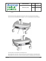
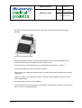
1
VascuLuminator
Reference guide
Document 3186-GEN05
Version 7.0
By R. Stemerdink
Date April 06
th
2011
VascuLuminator
Vein Imaging system
Reference guide
Revision history
Date
27-10-2010
19-11-2010
Version
Status
1.0
Concept
2.0
Releasse
08-12-2010
3.0
Release
15/12/10
4.0
Release
05/01/2011
5.0
Release
28/03/2011
6.0
Release
06/04/2011
7.0
for approval:
R. Stemerdink (name)
.......................... ....
DKMP bv,
Arnhem (NL).
Release
0344
Distribution
Description
DKMS bv
H. Jansen van Galen,
R. Stemerdink
First issue for comments
BF symbol added par.4.1
Updated for CE symbol, DoC and
location BF symbol
EMC paragraph added + small text
changes
Patient range and use scenarios
described; symbols added
Technical File
Technical File
Technical file
Technical file
IR applicator assembly instructions
Declaration of conformity
(signature)
..................................
Technical file
H. Jansen van Galen (name)
.................................
(signature)
......................................
1 / 50
VascuLuminator
Reference guide
Document 3186-GEN05
Version 7.0
By R. Stemerdink
Date April 06
th
2011
Index
TECHNICAL SPECIFICATION
5 1 Technical specification
6 1.1 General specifications
6 1.2 Isolation from supply means
8 1.3 Operation mode
8 1.4 Applied parts
8 1.5 Type and position of labels, warning signs and instructions
8 1.6 Software
9 1.7 Human machine interface
9 1.8 Installation instructions
9 1.9 Estimated service life
9 1.10 Operator level
9 1.11 Service personnel level
9 1.12 Safety and compatibility standards
10 1.13 Electro Magnetic Compatibility
12 USER MANUAL
17 2 General description
18 2.1 System description
18 2.2 Field of use
18 2.3 Use scenarios
18 2.4 Contraindications
20 2.5 Operator level
20 2.6 Environment
20 2.7 Disclaimer
20 2.8 Application specification summary
20 3 Contents of the packaging
21 4 Explanation of packaging en product symbols
22 4.1 Explanation of packaging en product symbols
22 4.2 Type and position of labels, warning signs and instructions
23 DKMP bv,
Arnhem (NL).
2 / 50
VascuLuminator
Reference guide
Document 3186-GEN05
Version 7.0
By R. Stemerdink
Date April 06
th
2011
5 Safety and compatibility standards
23 6 Caution & Warnings
25 7 System overview
26 8 Installation instructions
27 9 Operating instructions
30 9.1 Warnings
30 9.2 Controls
32 9.3 Use of the VascuLuminator
33 9.3.1 Charging the batteries
33 9.3.2 Using the VascuLuminator
33 The operator responsible for imaging
33 How to apply the VascuLuminator for imaging
34 IR applicator
34 Imaging
35 10 Cleaning instructions
37 11 Maintenance
37 12 TROUBLESHOOTING
37 13 Disposal
39 14 Storage & maintenance
39 SERVICE MANUAL
41 15 SERVICE ACTIONS
42 15.1 Technical specification
42 15.2 Installation instructions
42 15.3 Functions and operation
42 15.4 Troubleshooting
42 15.5 Maintenance and inspection
42 15.6 Power supply cord replacement
43 15.7 Fuse replacement
44 15.8 Battery replacement
46 15.9 IR applicator replacement
48 DKMP bv,
Arnhem (NL).
3 / 50
VascuLuminator
Reference guide
Document 3186-GEN05
Version 7.0
By R. Stemerdink
Date April 06
15.10 Remaining items
th
2011
48 16 Modifications
49 17 Disposal
49 18 Terms of warranty
50 18.1 General
50 18.2 Disinfection before shipment
50 18.3 Packaging
50 19 Contact information
DKMP bv,
Arnhem (NL).
50 4 / 50
VascuLuminator
Reference guide
Document 3186-GEN05
Version 7.0
By R. Stemerdink
Date April 06
th
2011
TECHNICAL SPECIFICATION
DKMP bv,
Arnhem (NL).
5 / 50
VascuLuminator
Document 3186-GEN05
Reference guide
Version 7.0
By R. Stemerdink
Date April 06
1
th
2011
Technical specification
1.1
General specifications
Packaging dimensions:
69 x 53 x 102 cm
Device dimensions:
54 x 48 x 165 cm (when in transport state)
Device weight (excl. packaging):
23 kg
Field of use:
indoor use only
Storage temperature range
-15 - +40oC
Storage relative humidity
25 – 85%
Operating temperature
+18° to + 30oC
Max. Altitude
+ 2000m above sealevel
Length of swivel arm:
1.05 m
Vertical camera adjustment:
0.5 -01.65 m (distance from floor level to camera)
Focus distance:
0.1-0.8 m
LED power:
80 mW max.
Batteries *:
NP7-12 (Lead acid 12V 7.2 Ah size 95x151x 65 mm
terminal size 4.8 mm, maintenance free) 2 pcs.
Charger:
DKMS bv charger type 330-00
Charger input voltage:
100-240Vac 50-60Hz
Charger output voltage:
Fast charge 14.7 V
Trickle charge 13.8 V
Fuses:
2 x 6A 250Vac/ 125Vdc fast blow on each battery connection (Littelfuse:
0314006.MXP)
1 x 1.5 A 250Vac/ 125Vdc fast blow on DC power line (Littelfuse:
032601.5MXP)
Protection class:
IP 20
IR applicator *
De Koningh Medical Systems type 410-00
DKMP bv,
Arnhem (NL).
6 / 50
VascuLuminator
Reference guide
Document 3186-GEN05
Version 7.0
By R. Stemerdink
Date April 06
th
2011
* : These parts can be ordered as a spare part at DKMP bv.
DKMP bv,
Arnhem (NL).
7 / 50
VascuLuminator
Reference guide
Document 3186-GEN05
Version 7.0
By R. Stemerdink
Date April 06
1.2
th
2011
Isolation from supply means
The VascuLuminator battery charger is coupled to the mains using a flexible power cord with connector.
The power cord must be disconnected from the mains before service actions are carried out.
1.3
Operation mode
The VascuLuminator is built for continuous operation. The VascuLuminator can be used for at least 10 hrs based on
fully charged batteries at the beginning of use.. The batteries need to be recharged for at least 8 hours after this time,
by connecting the charger to the mains supply.
1.4
Applied parts
The applied part in the VascuLuminator ( the only part that contacts the patient) is the infrared applicator. This part is
a type BF applied part, according to IEC 60601-1. This part is made of inert plastic materials which are safe for the
patient to touch.
1.5
Type and position of labels, warning signs and instructions
Type of media
Position
Providing
Information label
On packaging
General information, storage and handling prescriptions
Information label
On charger
Charger type and specification
Information label
On side of foot cover
VascuLuminator specifications
Warning label
On top of foot cover
Warning only to use charger model VascuLuminator 330-00
Warning label
On top of foot cover
Warning not to stand on foot cover
Warning label
Warning for unintended spring arm extension
Information label (2 pcs)
On swivel arm binder
(when in package)
Above 6A fuses
Information label
Above 1.5 A fuse
Fuse rating
Information engraving
BF class indication for applied part (IR-APPLICATOR)
Instruction
Fiber connector on arm
(backside of monitor)
Camera upper side
Instruction
Camera lower side
Knob turning direction of focus adjustment
Indicator light
On charger
Charging status (blue = fast charging; green = trickle
charging)
DKMP bv,
Arnhem (NL).
Fuse rating
Knob turning direction of IR intensity adjustment
8 / 50
VascuLuminator
Reference guide
Document 3186-GEN05
Version 7.0
By R. Stemerdink
Date April 06
Indicator light
1.6
In on / off button
th
2011
Battery status (green = charged; yellow = battery low)
Software
The VascuLuminator does not contain any dedicated software, neither is it in any way programmable.
1.7
Human machine interface
The VascuLuminator contains the following interfaces with the user:
-
The on / off button, mounted on the display. The button carries an indicator that lights green during normal
operation, and turns orange when the battery is low. The button is monostable.
-
The infrared intensity knob, mounted on top of the camera. The infrared light intensity can be adjusted by
turning this knob manually.
-
The focus knob, mounted on the bottom side of the camera. The focus distance can be adjusted by turning
this knob manually.
-
The screen, giving a visual representation of the camera image, in greytones.
-
The infrared applicator which is placed against a body part of the patient.
1.8
Installation instructions
For installation instructions, see chapter 8.
1.9
Estimated service life
The estimated service life of the VascuLuminator is 5 years.
1.10 Operator level
Operator profile for operating the VascuLuminator is: nursing personal at beginner and intermediate level who are
used to handling medical equipment, and who have the required skills and certifications to do injections and place
drip needles.
1.11 Service personnel level
Service personal profile for servicing the VascuLuminator is: technicians at beginner and intermediate level who are
used to handling and repairing medical electrical equipment.
DKMP bv,
Arnhem (NL).
9 / 50
VascuLuminator
Reference guide
Document 3186-GEN05
Version 7.0
By R. Stemerdink
Date April 06
th
2011
1.12 Safety and compatibility standards
For safety and compatibility standards, see the user manual chapter 5.
DKMP bv,
Arnhem (NL).
10 / 50
VascuLuminator
Reference guide
Document 3186-GEN05
Version 7.0
By R. Stemerdink
Date April 06
th
2011
DECLARATION OF CONFORMITY
Manufacturer
DKMP bv
Simon Stevinweg 48
6802 EA Arnhem
The Netherlands
Product
Model nr.
Serial nr.
Start production
VascuLuminator
001.00
34811-001
22 September 2010
Classification
Class IIa, Rule 10 according to Annex IX of the MDD
We hereby declare that the above mentioned product meet the provisions of the
Council Directive 93/42EEC for Medical Devices. All supporting is retained under
the premises of the manufacturer.
Conformity assessment route according to Annex V/VII
Standards applied
MEDDEV 2.7.1 REV.3:2009
NEN-EN 1041:2008
NEN-EN 980:2008
NEN-EN-IEC 60825:2008
NEN-EN-ISO 15223-1:2009
NEN-EN 60601-1:2006
NEN-EN 60601-1-2:2007
NEN-EN 60601-1-6:2010
NEN-EN-IEC 62366:2008
NEN-EN-ISO 14155-1:2009
NEN-EN-ISO 14155-2:2009
NEN-EN-ISO 14971:2009
Issue of CE marking
March 25 2011
Notified body
DEKRA Certification bv 0344
Utrechtseweg 310
6800 ET Arnhem
Place and date of issue
Arnhem, March 29 2011
H.P. Jansen v. Galen
QA manager
Signature
DKMP bv,
Arnhem (NL).
……………………………………………….
11 / 50
VascuLuminator
Reference guide
Document 3186-GEN05
Version 7.0
By R. Stemerdink
Date April 06
1.13
th
2011
Electro Magnetic Compatibility
Guidance and manufacture’s declaration – electromagnetic emissions
The VascuLuminator is intended to use in de electromagnetic environment specified below. The customer or the user
of the VascuLuminator should assure that it is used in such an environment.
Emissions Test
Compliance
Electromagnetic environment – guidance
RF emissions
Group 1
The VascuLuminator uses RF energy only for its
internal function. Therefore, its RF emissions are very
low and are not likely to cause any interference in
nearby electronic equipment
Class A
The VascuLuminator is suitable for use in all
establishments other than domestic, and may be used
in domestic establishments and those directly
connected to the public low-voltage power supply
network that supplies buildings used for domestic
purposes, provided the following warning is needed:
Warning: This equipment/system is intended for use
by healthcare professionals only.
This equipment / system may cause radio interference
or may disrupt the operation of nearby equipment.
It may be necessary to take mitigation measures, such
as re-orienting or relocating the VascuLuminator or
shielding the location.
CISPR 11
RF emissions
CISPR 11
Harmonic emissions
Class A
IEC 61000-3-2
Voltage fluctuations/ flicker
emissions
IEC 61000-3-3
DKMP bv,
Arnhem (NL).
Complies
12 / 50
VascuLuminator
Reference guide
Document 3186-GEN05
Version 7.0
By R. Stemerdink
Date April 06
th
2011
Guidance and manufacture’s declaration - electromagnetic immunity
The VascuLuminator is intended to use in de electromagnetic environment specified below. The customer or the user
of the VascuLuminator should assure that it is used in such an environment.
Immunity test
IEC60601 test
level
Compliance level
Electromagnetic environment guidance
Electromagnetic
discharge (ESD)
±6 kV contact
±6 kV contact
±8 kV air
±8 kV air
Floors should be wood, concrete or ceramic tile. If
floors are covered with synthetic material, the
relative humidity should be at least 30%
Electrical fast
transient / burst
±2 kV for power
supply lines
±2 kV for power
supply lines
Mains power quality should be that of a typical
commercial or hospital environment.
IEC 61000-4-4
±1kV for
input/output lines
±1kV for
input/output lines
Surge
±1 kV differential
mode
±1 kV differential
mode
±2 kV common
mode
±2 kV common
mode
<5 % UT
(>95 % dip in UT )
for 0.5 cycle
<5 % UT
(>95 % dip in UT )
for 0.5 cycle
40 % UT
(60 % dip in UT )
for 5 cycles
40 % UT
(60 % dip in UT )
for 5 cycles
70 % UT
(30 % dip in UT )
for 25 cycles
70 % UT
(30 % dip in UT )
for 25 cycles
<5 % UT
(>95 % dip in UT )
for 5 sec
<5 % UT
(>95 % dip in UT )
for 5 sec
3 A/m
3 A/m
IEC 61000-4-2
Mains power quality should be that of a typical
commercial or hospital environment.
IEC 61000-4-5
Voltage dips, short
interruptions and
voltage variations
on power supply
input lines
IEC 61000-4-11
Power frequency
(50/60 Hz) magnetic
field
Mains power quality should be that of a typical
commercial or hospital environment.
Power frequency magnetic fields should be at levels
characteristic of a typical location in a typical
commercial or hospital environment.
IEC 61000-4-8
NOTE: UT is the a.c. mains voltage prior to application of the test level.
Portable and mobile RF communications equipment
should not be used no closer to any part of the
VascuLuminator, including cables, than the
DKMP bv,
Arnhem (NL).
13 / 50
VascuLuminator
Document 3186-GEN05
Reference guide
Version 7.0
By R. Stemerdink
Date April 06
th
2011
Guidance and manufacture’s declaration - electromagnetic immunity
The VascuLuminator is intended to use in de electromagnetic environment specified below. The customer or the user
of the VascuLuminator should assure that it is used in such an environment.
Immunity test
IEC60601 test
level
Compliance level
Electromagnetic environment guidance
recommended separation distance calculated from
the equation applicable to the frequency of the
transmitter.
Recommended separation distance
d = 1.2 √ P
d = 1.2 √ P 80 MHz to 800 MHz
d = 2.3 √ P 800 MHz to 2.5 GHz
where P is the maximum output power rating of the
transmitter in watts (W) according to the transmitter
manufacturer and d is the recommended separation
distance in meters (m).
Conducted RF
IEC61000-4-6
Radiated RF
IEC61000-4-3
3 Vrms
150 kHz to 80
MHz
3 Vrms
3 V/m
80 MHz to 2.5
GHz
3 V/m
Field strengths from fixed RF transmitters, as
determined by an electromagnetic site surveya,
should be less than the compliance level in each
frequency rangeb.
Interference may occur in the vicinity of equipment
marked with the following symbol:
NOTE 1 At 80 MHz and 800 MHz, the higher frequency range applies.
NOTE 2 These guidelines may not apply in all situations. Electromagnetic propagation is affected by absorption and
reflection from structures, objects and people.
a
Field strengths from fixed transmitters, such as base stations for radio (cellular/cordless) telephones and land
mobile radios, amateur radio, AM and FM radio broadcast and TV broadcast cannot be predicted theoretically with
accuracy. To assess the electromagnetic environment due to fixed RF transmitters, an electromagnetic site survey
should be considered. If the measured filed strength in the location in which the VascuLuminator is used exceeds the
applicable RF compliance level above, the VascuLuminator should be observed to verify normal operations. If
abnormal performance is observed, additional measures may be necessary, such as reorienting or relocating the
VascuLuminator.
b
Over the frequency range 150 kHz to 80 MHz, field strengths should be less than 3 V/m
DKMP bv,
Arnhem (NL).
14 / 50
VascuLuminator
Reference guide
Document 3186-GEN05
Version 7.0
By R. Stemerdink
th
Date April 06
2011
Recommended separation distances between
portable and mobile RF communications equipment and the VascuLuminator
The VascuLuminator is intended for use in an electromagnetic environment in which radiated RF disturbances are
controlled. The customer or the user of the VascuLuminator can help prevent electromagnetic interference by
maintaining a minimum distance between portable and mobile RF communications equipment (transmitters) and the
VascuLuminator as recommended below, according to the maximum output power of the communications equipment.
Rated maximum output
Separation distance according to frequency of transmitter
power of transmitter
m
W
0,01
0,12
0,12
0,24
0,1
0,37
0,37
0,74
1
1,17
1,17
2,34
10
3,69
3,69
7,38
100
11,67
11,67
23,34
For transmitters rated at a maximum output power not listed above, the recommended separation distance d i n
meters (m) can be estimated using the equation applicable to the frequency of the transmitter, where P is the
maximum output power rating of the transmitter in watts (W) according to the transmitter manufacturer.
NOTE 1 At 80 MHz and 800 MHz, the separation distance for the higher frequency range applies.
NOTE 2 These guidelines may not apply in all situations. Electromagnetic propagation is affected by absorption and
reflection from structures, objects and people.
DKMP bv,
Arnhem (NL).
15 / 50
VascuLuminator
Reference guide
Document 3186-GEN05
Version 7.0
By R. Stemerdink
Date April 06
DKMP bv,
Arnhem (NL).
th
2011
16 / 50
VascuLuminator
Reference guide
Document 3186-GEN05
Version 7.0
By R. Stemerdink
Date April 06
th
2011
USER MANUAL
DKMP bv,
Arnhem (NL).
17 / 50
VascuLuminator
Reference guide
Document 3186-GEN05
Version 7.0
By R. Stemerdink
Date April 06
2
2.1
th
2011
General description
System description
If a bodypart is held under the camera, the display will show an image of that bodypart in grey tones. If the infrared
light source is held under the bodypart in such a way that the emitted light goes through the bodypart and into the
camera, the image will show the veins in the body part in dark tones, as veins filled with blood obstruct the path of the
infrared light.
The VascuLuminator consists of a stand that supports a swivel arm. The swivel arm carries the display and camera.
An applicator is attached to the system, emitting infrared light.
2.2
Field of use
Indications for use are patients that need a venipuncture in a thin body extension, especially the hand, in which the
vessels are hardly, or not at all, visible or palpable, or when the performer of the procedure needs a better vision in
order to determine the location, direction or size of the blood vessels, in order to make a better judgment which vein
or artery is suitable for puncture.
The VascuLuminator can be used for patients of any age, weight, health and condition.
2.3
Use scenarios
The VascuLuminator is a mobile device that can be moved to the patient area.
The swivel arm on the stand allows the user to bring the camera and display to the desired position, without having to
move the whole device.
The display arm can be rotated over almost 360° so that the optimal position of the display can be realized without
having to move the device, the swivel arm, the patient or the user.
The camera and display can be tilted over ±15 degrees in vertical direction for optimal visability.
The device can be switched on at any moment, before or after positioning the device and the camera.
Switching off the device is allowed at any moment after use.
When using the device for a longer time, the device is allowed to remain switched on.
See following schematic representations.
DKMP bv,
Arnhem (NL).
18 / 50
VascuLuminator
Reference guide
Document 3186-GEN05
Version 7.0
By R. Stemerdink
Date April 06
th
2011
The reach of the swivel arm enables the use of the VascuLuminator in several positions. Examples:
1.
Both patient and user sitting on chairs, the VascuLuminator being positioned somewhere aside of patient
and user (top view)
patient
user
VascuLuminator
2.
The patient laying or sitting in a hospital bed, the user positioned next to the bed (top view)
patient
user
VascuLuminator
3.
Young child laying in an incubator, the user positioned next to the incubator (top view)
user
incubator
with child
VascuLuminator
DKMP bv,
Arnhem (NL).
19 / 50
VascuLuminator
Reference guide
Document 3186-GEN05
Version 7.0
By R. Stemerdink
Date April 06
2.4
th
2011
Contraindications
There is no contra-indication for the use of the VascuLuminator.
2.5
Operator level
Operator profile for operating the VascuLuminator is: nursing personal at beginner and intermediate level who are
used to handling medical equipment, and who have the required skills and certifications to do injections and place
drip needles.
2.6
Environment
The VascuLuminator is ment for indoor use only. The device is equipped with antistatic wheels and can be moved.
2.7
Disclaimer
The VascuLuminator is not intended for distinguishing veins from arteries.
The VascuLuminator may not visualize small vessels or vessels that lay deeper in the body.
Infrared light from the environment, such as direct sun light and halogen light sources may have a negative influence
on the resulting image. The image on the monitor will show up over exposed. Visible light sources typically used in
hospitals will not diminish proper performance of the VascuLuminator.
2.8
Application specification summary
System description
Field of use
Patient population
Contraindications
Operator level
Environment
Use limitations
DKMP bv,
Arnhem (NL).
An infrared light source held under body part allows camera with infrared filter to
detect the position of veins in the body part, as blood is less translucent for
infrared light than tissue. A representation of the vein position is shown in
greytones on a display.
Making the position of veins visible in thin body extensions, esp. hand, when
required for venipunctures
Patients of any age, weight, health and condition
None
Medical personnel, skilled and certified for doing injections and placing drip
needles
Indoor use only
limited visibility of smaller veins, and veins that lay deeper in the body
no diffirence in representation of veins and arteries
direct sunlight and bright light sources may influence the quality of the
representation on the screen.
20 / 50
VascuLuminator
Reference guide
Document 3186-GEN05
Version 7.0
By R. Stemerdink
Date April 06
3
th
2011
Contents of the packaging
VascuLuminator stand
VascuLuminator arm with
monitor and camera
Battery charger model
VascuLuminator 330-00
Power cable (EU- 220V/50Hz)
IR-Applicator (No410-00)
Swivel arm support clamp
M6 - Bolt
Allen wrench 2 pcs.
(4 mm and 1.5 mm)
DKMP bv,
Arnhem (NL).
21 / 50
VascuLuminator
Reference guide
Document 3186-GEN05
Version 7.0
By R. Stemerdink
th
Date April 06
2011
DKMS bv Reference guide
4
4.1
Explanation of packaging en product symbols
Explanation of packaging en product symbols
Conformité Europénne (European Conformity). This symbol means that the device fully complies
with MDD directive 93/42/EEC (Notified Body 0344 = KEMA)
0344
Do not dispose of this product in the unsorted waste stream. Dispose of this product according to
local regulations
Consult instructions for use
Manufacturer
Keep package straight up during transportation. This side up.
Keep dry
Date of manufacturing (month – Year)
Package contains fragile contents
Do not step
DKMP bv,
Arnhem (NL).
22 / 50
VascuLuminator
Document 3186-GEN05
Reference guide
Version 7.0
By R. Stemerdink
th
Date April 06
2011
Applied part is class BF
Maximum and minimum storage temperature
40°C
Maximum and minimum storage humidity
-15°C
For indoor use only
4.2
Type and position of labels, warning signs and instructions
See chapter 1.5.
5
Safety and compatibility standards
The VascuLuminator is a Class IIa medical device.
The VascuLuminator complies with the following standards:
IEC 60601-1,
Medical electrical equipment safety
IEC 60601-1-2,
Electromagnetic compatibility
EN 980:2008
Symbols for use in the labelling of medical devices
EN 1041:2008
Information supplied by the manufacturer of medical devices
EN ISO 13485:2003
Medical devices - Quality Management Systems - Requirements for regulatory purposes
EN ISO 14971:2009
Medical devices - Application of risk management to medical devices
DKMP bv,
Arnhem (NL).
23 / 50
VascuLuminator
Reference guide
Document 3186-GEN05
Version 7.0
By R. Stemerdink
Date April 06
th
2011
EN 60601-1-6:2007
Medical electrical equipment - Part 1-6: General requirements for safety - Collateral
standard: Usability
EN 62366:2008
Medical devices - Application of usability engineering to medical devices
EN ISO 14155-1:2003
Clinical investigation of medical devices for human subjects - Part 1: General requirements
MEDDEV2,7/1 rev.3 :2009 Clinical evaluation: Guide for manufacturers and notified bodies
NEN-EN ISO 60825
DKMP bv,
Arnhem (NL).
Safety of laser products
24 / 50
VascuLuminator
Reference guide
Document 3186-GEN05
Version 7.0
By R. Stemerdink
th
Date April 06
6
2011
Caution & Warnings
The VascuLuminator is designed for indoor use only.
Do not remove the binder that keeps the arm bend together until the arm is mounted and fixed on the
VascuLuminator support clamp! Removing the binder while the arm is not installed properly may cause
unintended stretching of the arm!
Do not stand on the support of the VascuLuminator
Do not attach any items onto the VascuLuminator. The arm is not designed to carry any additional weight. In
stretched situation additional weight might overturn the VascuLuminator!
The VascuLuminator is only allowed to operate in combination with the dedicated VascuLuminator charger
model 330-00.
To avoid risk of electric shock, this equipment must only be connected to a supply mains with protective
earth.
The camera shall be in locked position using the camera clamp with the
monitor facing towards the stand during travel of the VascuLuminator.
The VascuLuminator is designed to be moved around locally. Traveling the
system over greater distances, and unsmooth floorsurfaces will increase
wear on the wheels or might damage them.
When the VascuLuminator is in operation, infrared light is emitted from the
IR-APPLICATOR. However the infrared light is of a low intensity, it is not
recommended to look directly into the infrared light beam from close distance
If any of the identification markings are removed before or during use, please contact your service supplier.
The electronics inside the Vasculuminator will generate heat that will be dissipated through the IR
adjustment knob on the camera, the rear surface of the display and the infrared fiber connector on the rear
side of the arm.
However these temperatures will be well below the limits that the safety regulations prescribe, the surfaces
will reach considerable temperatures.
See the Technical Description for the limits of use, such as minimum and maximum temperature etc.
DKMP bv,
Arnhem (NL).
25 / 50
VascuLuminator
Reference guide
Document 3186-GEN05
Version 7.0
By R. Stemerdink
th
Date April 06
7
2011
System overview
Ws
hs
D
ts
E
bs E .
rs
1 ks E .
(s
4s
xs
a
Wl s 1
WWs
1
Whs f
E .
E ebSw
t t l fl l E E
1
1 1
1
1
6
7
1 D
5
bWl fl l
4
3
8
8
9
12
2
10
1
11
DKMP bv,
Arnhem (NL).
26 / 50
VascuLuminator
Reference guide
Document 3186-GEN05
Version 7.0
By R. Stemerdink
th
Date April 06
8
2011
Installation instructions
Caution before installation
Do not remove the binder that keeps the arm bend together until the arm is mounted and fixed on the
VascuLuminator support clamp! Removing the binder while the arm is not installed properly may cause
unintended stretching of the arm!
Installation of the VascuLuminator:
1.
Slide the Swivel arm support clamp (4) over the Lower VascuLuminator support (3)
2.
Connect the plug that protrudes from the upper part of the VascuLuminator
into the socket like shown
3.
Shift the Swivel arm assembly (5) into the Distribution support (be careful to not damage
wires and connections!). Rotate the Distribution support and align the holes of the
Distribution support with those of the Lower VascuLuminator support.
4.
Rotate the Swivel arm support clamp (4) to align all the holes
5.
Mount the screw fixating the arm onto the stand.
6.
Connect the power cable to the battery charger and place the charger in the bracket.
The power cord has to be at the bottom side of the cradle. See
following pictures.
DKMP bv,
Arnhem (NL).
27 / 50
VascuLuminator
Reference guide
Document 3186-GEN05
Version 7.0
By R. Stemerdink
Date April 06
Correct installation:
Power cord at bottom of cradle
th
2011
Incorrect installation: power cord upward and charger
and charger cable downward
Connect the charger plug into the stand. Due to its shape, the charger plug can only be mounted to the
connector in one position.
After placing the connector, turn the locking nut so that the plug is fixed in the connector.
plug with locking nut
7.
Remove the binder holding the arm together.
8.
Mount the IR applicator into the applicator holder.
Push the metal bush on the end of the IR applicator cable into the fiber connection bush. See
following pictures.
metal bush
DKMP bv,
Arnhem (NL).
28 / 50
VascuLuminator
Reference guide
Document 3186-GEN05
Version 7.0
By R. Stemerdink
Date April 06
th
2011
While pushing the fiber end in the bush, turn the two set screws in the fiber connection bush
clockwise to fix the fiber into the connection bush.
fiber connection bush on rear side of display arm
set screws
IR applicator fiber cable end
WARNING: be careful when tightening the set screws. Turning with too much torque might
damage the fiber end. The set screws should be turned gently against the fiber end, to
prevent it from slipping out.
The VascuLuminator is now ready for use.
DKMP bv,
Arnhem (NL).
29 / 50
VascuLuminator
Reference guide
Document 3186-GEN05
Version 7.0
By R. Stemerdink
th
Date April 06
9
9.1
2011
Operating instructions
Warnings
The VascuLuminator is designed for indoor use only.
Only move the VascuLuminator by holding the blue segment of the
VascuLuminator support as shown on the picture right.
The VascuLuminator is designed to be moved around locally. Moving the
system over greater distances, and unsmooth floorsurfaces will increase
wear on the wheels or damage them.
Do not suspend anything from the swivel arm as this may damage the
VascuLuminator, or make it instable
The VascuLuminator is designed only to be used with a battery charger model VascuLuminator nr 330-00.
To avoid risk of electric shock, this equipment must only be connected to a supply mains with protective
earth.
The user is only allowed to perform the operations that are described in the user manual.
Maintenance and repair is to be carried out only by qualified service personnel.
The IR applicator shall be treated with care, as its cable contains glass fibers which are vulnerable. Do not
bend the cable too tighly.
The electronics inside the Vasculuminator will generate heat that will be dissipated through the IR
adjustment knob on the camera, the rear surface of the display and the infrared fiber connector on the rear
side of the arm.
However these temperatures will be well below the limits that the safety regulations prescribe, the surfaces
will reach considerable temperatures.
DKMP bv,
Arnhem (NL).
30 / 50
VascuLuminator
Reference guide
Document 3186-GEN05
Version 7.0
By R. Stemerdink
Date April 06
DKMP bv,
Arnhem (NL).
th
2011
31 / 50
VascuLuminator
Reference guide
Document 3186-GEN05
Version 7.0
By R. Stemerdink
Date April 06
9.2
th
2011
Controls
9 = on / off button with indicator; green = on and batteries are charged, yellow = on and batteries are low
10 = InfraRed light intensity adjustment knob
11 = camera focus ring
9
10
11
DKMP bv,
Arnhem (NL).
32 / 50
VascuLuminator
Reference guide
Document 3186-GEN05
Version 7.0
By R. Stemerdink
Date April 06
9.3
9.3.1
th
2011
Use of the VascuLuminator
Charging the batteries
1. Connect the power cord to the mains.
2. The indicator on the charger should now become blue or green.
If the light is blue, the charger is fast charging, which means that the batteries needed recharging.
If the indicator is green, the charger is trickle charging which means that the batteries are nearly
filled, or are completely filled and the charger is maintaining the battery charge.
The VascuLuminator is built for continuous operation. When the batteries are fully charged, the VascuLuminator can
operate for at least 10 hours.
The batteries need to be recharged for at least 8 hours after this time, by connecting the charger to the mains supply.
9.3.2
Using the VascuLuminator
1.
Turn the VascuLuminator on by pressing the on/off button (9). The button will light up green when switched
on. An image will appear on the display after a few seconds.
2.
If the button lights up yellow, the batteries need recharging, however the VascuLuminator can still be used for
some time. Recharging of the batteries in this case is recommended!
3.
After use, switch off the VascuLuminator by pushing the on / off button.
4.
If the power cord was detached during use, it is recommended to reconnect it to the mains after use to keep
the batteries fully charged.
The operator responsible for imaging
The operator of the VascuLuminator in an imaging situation is an operator experienced in dealing with patients in a
clinical environment and used to performing venipunctures.
The operator will perform all imaging operations and guide the patients hand to optimally image the desired area for
venipuncture. Operations performed will be adjusting the intensity and focus and guiding the patients hand while
observing the image on the display.
DKMP bv,
Arnhem (NL).
33 / 50
VascuLuminator
Document 3186-GEN05
Version 7.0
By R. Stemerdink
Reference guide
Date April 06
th
2011
How to apply the VascuLuminator for imaging
IR applicator
1
Align the IR applicator with the transparent side up.
When the VascuLuminator is turned on a red spot will be visible.
IR applicator – Transparant side up
Emission from the infrared source will
radiate upwards
2
Place the hand for imaging above the IR applicator.
The radiant side of the IR applicator will
now be facing the imaging hand
3 Press the IR applicator with the transparent side up to the imaging hand
The radiant side of the IR applicator will
now be lighting the imaging hand
DKMP bv,
Arnhem (NL).
34 / 50
VascuLuminator
Reference guide
Document 3186-GEN05
Version 7.0
By R. Stemerdink
Date April 06
th
2011
Imaging
4
Align both hands to the imaging camera
Imaging camera
Align and move both hands towards the
imaging camera
5
Move both your hands upwards, approximately 10 – 15 cm towards the imaging camera
When the VascuLuminator is turned on,
a greytone image should now appear on
the screen
Keep a distance of approximately
10 to 15 cm from the camera
DKMP bv,
Arnhem (NL).
35 / 50
VascuLuminator
Reference guide
Document 3186-GEN05
Version 7.0
By R. Stemerdink
Date April 06
6
th
2011
Optimise the image by adjusting distance, intensity and focus
Due to the approximate distance to the camera, both dials need to be used to help optimise intensity
and focus of the image.
To display a clear image of the desired point of venipuncture move the hand while turning the dials of
the intensity and focus. The VascuLuminator operator in this case will be adjusting the dials
respectively with one hand wile moving the patients hand with the other.
To optimize the image both focus and
intensity can be adjusted
Imaging screen, with a clear image of the
veins in the hand. The veins on the
screen show up in greytones
Dial to optimize image intensity
Dial to optimize image focus
7
Turn the focus and intensity dials respectively to display a clear image of the veins in the hand.
The intensity dial displays the following symbol:
The focus dial displays the following symbol:
Turning the focus dial counter clockwise (seen from above) the focus distance is increased.
DKMP bv,
Arnhem (NL).
36 / 50
VascuLuminator
Reference guide
Document 3186-GEN05
Version 7.0
By R. Stemerdink
th
Date April 06
2011
Turning the focus dial clockwise (seen from above) the focus distance is decreased.
The focus can be adjusted to any distance between ~ 0.1 and 0.8 m.
Turning the intensity dial counter clockwise (seen from above) the intensity is decreased.
Turning the intensity dial clockwise (seen from above) the intensity is increased.
10 Cleaning instructions
Before cleaning, turn off the VascuLuminator and disconnect the power cord from the mains.
Clean the outer surface of the VascuLuminator including the IR- applicator light source with a soft cloth of tissue
dampened with a pH neutral disinfecting solution, mild detergent or an ethanol 70% max.
Do not soak the activation button and do not spray detergents or other liquids directly on to the VascuLuminator.
Do not sterilize the VascuLuminator or the IR-applicator by any means!
11 Maintenance
In case any irregularities are detected in operating the VascuLuminator, such as loose parts or malfunctioning, the
VascuLuminator should be inspected by qualified service personal.
Service actions are only allowed for qualified service personnel. The only corrective actions that are allowed for the
user are mentioned in chapter 12 Troubleshooting, item 1a and 1b.
The VascuLuminator is designed for a service life of 5 years. The performance of the batteries however may decline
during the lifetime, depending on the number and time of the charging cycles. The batteries are replacement parts
and if necessary they can be replaced by qualified service personnel.
12 TROUBLESHOOTING
1a
1b
Failure
Possible failure cause
Actions allowed for the user
VascuLuminator does not
start up and start button
does not light up green or
yellow after pushing the
start button
Charger is not connected
and batteries are empty
Molex connector at stand
connection was not
connected after assembly
of the VascuLuminator
Connect charger and push start button
again. Charge the batteries over > 8 hours
Place the binder on the swivel arm.
Disassemble the arm. Reconnect the
Molex connector between the stand wires
and the swivel arm wires and assemble the
arm
The actions below are only
allowed for service personal
DKMP bv,
Arnhem (NL).
37 / 50
VascuLuminator
Reference guide
Document 3186-GEN05
Version 7.0
By R. Stemerdink
Date April 06
1c
Molex connector on
footplate wires not
reconnected after
replacing batteries
Fuse 1.5 A blown
1d
2a
2b
3a
3b
4a
4b
VascuLuminator batteries
run empty fast (<8 hours)
after being charged
completely (> 8 hours)
Batteries are not fully
charged after more than 8
hours of charging
Batteries are worn out
2011
Reconnect the Molex connector between
the stand wires and the swivel arm wires
Replace 1.5 A fuse and check functioning
of the VascuLuminator. If the fuse blows
again, the VascuLuminator should be
investigated by the manufacturer
Replace both batteries
One battery fuse is blown Check the 6 A battery fuses and replace if
necessary. Check the functioning of the
VascuLuminator. If a fuse blows again,
replace the corresponding battery.
Batteries are worn out
Replace both batteries
Charger malfunction
No or only little infrared light Fiber cable is completely
is emitted from the IR
of partially broken
applicator
Infrared led does not
work
4c
th
Fiber cable is not
completely pushed into
the fiber connection bush
on the suspension arm
Check charger connector on foot plate.
Replace the complete IR applicator
Remove the fiber from the connector.
Observe if the IR led is emitting (red light is
visible inside the connector). If the IR led is
broken, contact the manufacturer for repair
Turn the set screws anticlockwise and
puhs the fiber into the fiber bush as far as
possible. Tighten the set screws again.
If the scheme above is followed but does not lead to improvement, the VascuLuminator should be investigated by the
manufacturer.
DKMP bv,
Arnhem (NL).
38 / 50
VascuLuminator
Reference guide
Document 3186-GEN05
Version 7.0
By R. Stemerdink
Date April 06
th
2011
13 Disposal
Do not dispose of this product in the unsorted waste stream.
Dispose of this product according to local regulations.
The product contains lead acid batteries that should be handled with care.
Batteries shall not be short-circuited . Neither should their enclosing be damaged because sulphuric acid may be
spilled.
14 Storage & maintenance
The batteries require an auxiliary charge (refresh charge) every 6 months when stored at temperature between 20
o
and 40 C .
The batteries are best to be charged at least within 6 months after manufacturing date.
DKMP bv,
Arnhem (NL).
39 / 50
VascuLuminator
Reference guide
Document 3186-GEN05
Version 7.0
By R. Stemerdink
Date April 06
DKMP bv,
Arnhem (NL).
th
2011
40 / 50
VascuLuminator
Reference guide
Document 3186-GEN05
Version 7.0
By R. Stemerdink
Date April 06
th
2011
SERVICE MANUAL
DKMP bv,
Arnhem (NL).
41 / 50
VascuLuminator
Reference guide
Document 3186-GEN05
Version 7.0
By R. Stemerdink
th
Date April 06
2011
15 SERVICE ACTIONS
Before a service action is carried out, the 230V AC mains must be disconnected.
Maintenance and repair is to be carried out only by qualified service personnel.
15.1 Technical specification
See the document part “Technical specification” chapter 1.1 to 1.12 for all technical data.
15.2 Installation instructions
See the document part “User manual” chapter 8 for installation instructions.
15.3 Functions and operation
See the document part “User manual” chapter 2 to 14 for intended use and operation of the
VascuLuminator.
15.4 Troubleshooting
See the document part “User manual” chapter 12 for troubleshooting.
15.5 Maintenance and inspection
In case any irregularities are detected in operating the VascuLuminator, such as loose parts or
malfunctioning, the VascuLuminator should be investigated by qualified service personal.
Service actions are only allowed for qualified service personal. The only corrective actions that are allowed
for the user are mentioned in chapter 12 Troubleshooting, item 1a and 1b.
The VascuLuminator is designed for a service life of 5 years. The performance of the batteries however may
decline during the lifetime, depending on the number and time of the charging cycles. The batteries are
replacement parts and if necessary they can be replaced by qualified service personal.
DKMP bv,
Arnhem (NL).
42 / 50
VascuLuminator
Reference guide
Document 3186-GEN05
Version 7.0
By R. Stemerdink
Date April 06
th
2011
15.6 Power supply cord replacement
If the power cord is damaged, it should be replaced by a proper power cord that complies to the
applicable standards.
DKMP bv,
Arnhem (NL).
43 / 50
VascuLuminator
Reference guide
Document 3186-GEN05
Version 7.0
By R. Stemerdink
th
Date April 06
2011
15.7 Fuse replacement
The VascuLuminator is provided with 3 fuses. Each battery has a 6 A fuse in the positive voltage
line. The power line that leads through the stand is provided with a 1.5 A fuse.
The 6 A fuses are placed on the same side of the stand tube bracket. The 1.5 A fuse is placed on
the opposite side.
The type of the fuses is 6 x 32 mm 250Vac/125Vdc fastblow.
In order to replace a fuse, the foot cover screws, located on the bottom of the stand need to be
removed. The foot cover can then be lifted up in such way that the stand bracket with the fuse
holders is accessible.
Make sure the swivel arm is in a locked position when tumbling the VascuLuminator in
order to reach the screws located on the bottom of the system. The camera should be
locked in the clamp on the tube stand, or a binder should be placed around the swivel arm
segments to prevent it from stretching unintentionally.
To improve accessibility of the foot cover screws, the VascuLuminator can be laid on its side.
Click the camera in the camera holder before doing so, and lay the VascuLuminator on its side
gently. Mind that the swivel arm tends to move outward when it lays on its side, as the weight of
the camera and display no longer holds the arm down.
Remove the six screws of the foot cover.
screws
DKMP bv,
Arnhem (NL).
44 / 50
VascuLuminator
Reference guide
Document 3186-GEN05
Version 7.0
By R. Stemerdink
Date April 06
th
2011
screws
Put the VascuLuminator upright again. Remove the 230V AC connector from the charger.
The foot cover can now be lifted up over approx. 10 cm. The fuse holders are now accessible.
6A fuse
6A fuse
1.5 A
The fuse holder can be opened by unscrewing the cap.
After replacement of the fuses, check the function of the VascuLuminator. If the replaced fuse
blows again after a short time, the VascuLuminator should be investigated by the manufacturer.
DKMP bv,
Arnhem (NL).
45 / 50
VascuLuminator
Reference guide
Document 3186-GEN05
Version 7.0
By R. Stemerdink
Date April 06
th
2011
15.8 Battery replacement
The batteries are maintenance-free.
When the performance of the batteries decreases when they reach the end of their lifetime, they
shall be replaced with the same type batteries. Model: NP7-12
It is recommended to replace the batteries every 3 years.
In case of battery replacement, the foot cover should be moved upward as far as possible, to
ensure accessibility of the battery compartment.
Remove the swivel arm as described before.
The six fastening screws of the foot cover should be removed (see 2.1). Put the VascuLuminator
upright again.
Remove the charger from its cradle, and remove the charger cradle from the stand by unscrewing
the two countersunk screws.
The foot cover can now be shifted along the stand tube. When doing so be aware of the wires
that lead to the charger connector!. Disconnect the connector (see picture) and remove the
footcover.
connector under foot plate
DKMP bv,
Arnhem (NL).
46 / 50
VascuLuminator
Reference guide
Document 3186-GEN05
Version 7.0
By R. Stemerdink
Date April 06
th
2011
Disconnect the red and black wires from the terminals. Unscrew the brackets that hold the
batteries.
hexagon socket M4x6 screws
Replace the batteries. See the Technical Specifications for the recommended battery type.
Place the brackets again and attach them with the M4 screws.
Connect the wires to the terminals with the corresponding colors (Red = +, Black = -) .
Lower the foot plate and connect the Molex connector.
Place the foot cover back in its original position and place the foot plate screws and the charger
cradle again.
Place the charger in the cradle with the 230 V connector facing downwards, and connect the
power cable in again.
Reassemble the swivel arm to the stand tube.
The first time that the VascuLuminator is used with the new batteries, connect the charger to the
mains in order to charge the batteries.
DKMP bv,
Arnhem (NL).
47 / 50
VascuLuminator
Reference guide
Document 3186-GEN05
Version 7.0
By R. Stemerdink
Date April 06
th
2011
15.9 IR applicator replacement
If the IR applicator needs replacement, turn the two set screws in the fiber connection bush that
is mounted on the suspension arm 2 turns anticlockwise and pull the fiber end out of the fiber
connection bush.
set screws in fiber
connection bush
Push a the loose fiber end of a new IR applicator into the fiber connection bush as far as
possible. Turn the set screws clockwise to fix the fiber end in the bush.
15.10 Remaining items
For information regarding electrical schemes, component data etc. please contact the
manufacturer.
See chapter 19 for contact information.
DKMP bv,
Arnhem (NL).
48 / 50
VascuLuminator
Reference guide
Document 3186-GEN05
Version 7.0
By R. Stemerdink
Date April 06
th
2011
16 Modifications
The VascuLuminator shall not be modified in any way.
17 Disposal
Do not dispose of this product in the unsorted waste stream.
Dispose of this product according to local regulations.
The product contains lead acid batteries that should be handled with care.
Waste batteries should not be short-circuited . Neither should their enclosing be damaged, because they may spill
sulphuric acid.
DKMP bv,
Arnhem (NL).
49 / 50
VascuLuminator
Reference guide
Document 3186-GEN05
Version 7.0
By R. Stemerdink
Date April 06
th
2011
18 Terms of warranty
18.1 General
DKMS bv warrants that the VascuLuminator, Vein imaging system will be free from defects in material and
workmanship and will conform to DKMP bv applicable specifications. If products sold hereunder are not as warranted,
DKMS bv shall, at its discretion either refund the purchase price, or repair or replace the product, provided proof of
purchase and written notice of non conformance are received by DKMP bv within the applicable warranty period. The
warranty set forth above does not extend to and shall not apply to products which have been repaired or altered by
persons other than DKMP bv personnel. They also do not apply to products that fail or are damaged due to shipment,
handling or storage or operation, use or maintenance in a manner or environment that does not conform to DKMP bv
published instructions and specifications. Batteries/accumulators, moving parts and failures due to such components
are also excluded. The warranty set forth above are in lieu of all other warranties expressed or implied, statutory or
otherwise, including warranties of merchantability and fitness for a particular purpose which DKMP bv disclaims.
18.2 Disinfection before shipment
In case the VascuLuminator is returned to DKMP bv, the device should be disinfected first, using a cloth with 70%
ethanol solution. See chapter 10 for cleaning instructions. The VascuLuminator should be accompanied by a signed
document confirming that the device is disinfected before shipping.
In case this document is not send with the device, the time required by DKMP bv for inspection and return of the
device will be influenced.
18.3 Packaging
In case the VascuLuminator is returned to DKMP bv, the original packaging should be used. The IR applicator is
vulnerable to bending and should be packed in the original protection box with foam inlay.
19 Contact information
De Koningh Medical Products bv
Simon Stevinweg 48
6827 BT, Arnhem
The Netherlands
Tel: +31 26 3849021
Fax: +31 26 3849066
Email: [email protected]
Website: www.dkmp.nl
0344
DKMP bv,
Arnhem (NL).
50 / 50