1
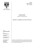
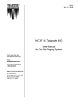
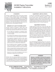
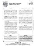
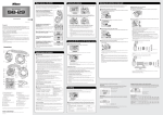
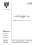
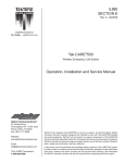
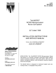
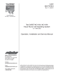
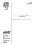
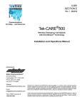
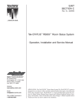
SI005 LED Messaging Sign
Operation, Installation and Service Manual
R
TekTone
Sound & Signal Mfg., Inc.
Website:
Email:
Address:
Phone:
Fax:
www.tektone.com
[email protected]
277 Industrial Park Rd.
Franklin, NC 28734
United States
828 524-9967
800 327-8466 (Toll Free)
Tech Support – Option 2
Sales – Option 3
828 524-9968
IL891 — March 2010 — Rev. 1
Abstract
The SI005 LED Messaging Sign can be used to provide ancillary annunciation of calls placed on the TekCARE400 Nurse Call and Tek-CARE500 Emergency Call systems. Annunciation is visual and can be accompanied by an optional tone. The SI005 acts like a pager: it receives a wireless transmission and then
subsequently clears the call after a programmed time.
If the nurse call system has been set up for manual text messaging, the SI005 can provide this functionality as well.
The SI005 sign is provided with default settings; changes are made by sending a manual text message to
the sign. The SI005 CAP Code is pre-programmed at the factory. For reprogramming CAP Codes, software
(LS005) is available separately, and runs on a laptop computer. The software package may be used for
multiple signs.
IL891 — SI005 LED Messaging Sign
Rev. 1
Operation, Installation and Service Manual
R
c 2003-2010 TekTone
Copyright Sound & Signal Mfg., Inc., All rights reserved.
R
No part of this publication may be copied without the express written permission of TekTone
Sound &
Signal Mfg., Inc. The content of this manual is furnished for informational use only, is subject to change
R
without notice, and should not be construed as a commitment by TekTone
Sound & Signal Mfg., Inc.
R
TekTone Sound & Signal Mfg., Inc. assumes no responsibility or liability for any errors or inaccuracies that
may appear in this documentation.
TekTone, the TekTone logo, Tek-Bridge, Tek-Call, Tek-Care, Tek-Check-In, Tek-Com, Tek-Digicare, TekDoor, Tek-Entry III, Tek-Guard, Tek-Micro, Tek-Micro II, Tek-MMARS II, TekNIOS, TekNIOS II, Tek-Paging,
Tek-Phone, Tek-Safe, Tek-Select II, Tek-Sentry, Tek-Sound, Tek-Status, Tek-Trio and Tek-View are either regR
istered trademarks or trademarks of TekTone
Sound & Signal Mfg., Inc. in the United States and/or other
countries. All other trademarks are the property of their respective owners.
R
Sound & Signal Mfg., Inc., 277 Industrial Park Road, Franklin, North Carolina 28734, USA.
TekTone
ii
IL891 — SI005 LED Messaging Sign
Rev. 1
About This Manual
This manual is designed to assist with installation of this TekTone product. Each component of the system is
described with step-by-step instructions to facilitate hardware installation and software configuration.
1. Important: Please take all precautions against high voltage shock. This is a mains powered unit.
1. Important: Please use proper mounting techniques to accommodate a fixture that exceeds 8 pounds.
iii
IL891 — SI005 LED Messaging Sign
Rev. 1
Contents
1 Theory of Operation
1
2 General
2.1 What is in the box . . . . . . . . . . . . . . . . . . . . . . . . . . . . . . . . . . . . . . . . . .
2.2 Features . . . . . . . . . . . . . . . . . . . . . . . . . . . . . . . . . . . . . . . . . . . . . . . .
2
2
2
3 Installation
3.1 Mounting . . . . . . . . . . . . . . . . . .
3.2 Programming . . . . . . . . . . . . . . . .
3.2.1 List of System Installation Manuals
3.2.2 Programming . . . . . . . . . . . .
3.3 Optional LS005 Programming Software .
3.3.1 LS005 Software Direct Connect . .
3.4 Programming Notes . . . . . . . . . . . .
3.5 System Testing . . . . . . . . . . . . . . .
.
.
.
.
.
.
.
.
3
3
3
4
4
4
4
6
6
4 User Manual
4.1 Factory Pre-Programming . . . . . . . . . . . . . . . . . . . . . . . . . . . . . . . . . . . . . .
4.2 Manual Text Messaging . . . . . . . . . . . . . . . . . . . . . . . . . . . . . . . . . . . . . . .
8
8
8
.
.
.
.
.
.
.
.
.
.
.
.
.
.
.
.
.
.
.
.
.
.
.
.
.
.
.
.
.
.
.
.
.
.
.
.
.
.
.
.
.
.
.
.
.
.
.
.
.
.
.
.
.
.
.
.
.
.
.
.
.
.
.
.
.
.
.
.
.
.
.
.
.
.
.
.
.
.
.
.
.
.
.
.
.
.
.
.
.
.
.
.
.
.
.
.
.
.
.
.
.
.
.
.
.
.
.
.
.
.
.
.
.
.
.
.
.
.
.
.
.
.
.
.
.
.
.
.
.
.
.
.
.
.
.
.
.
.
.
.
.
.
.
.
.
.
.
.
.
.
.
.
.
.
.
.
.
.
.
.
.
.
.
.
.
.
.
.
.
.
.
.
.
.
.
.
.
.
.
.
.
.
.
.
.
.
.
.
.
.
.
.
.
.
.
.
.
.
.
.
.
.
.
.
.
.
.
.
.
.
.
.
.
.
.
.
.
.
.
.
.
.
.
.
A Appendix
9
A.1 Other Figures . . . . . . . . . . . . . . . . . . . . . . . . . . . . . . . . . . . . . . . . . . . . .
9
A.2 Other Tables . . . . . . . . . . . . . . . . . . . . . . . . . . . . . . . . . . . . . . . . . . . . . . 11
B A Word about ESD (Electrostatic Discharge)
13
iv
IL891 — SI005 LED Messaging Sign
Rev. 1
Chapter 1
Theory of Operation
Similar to TekTone’s Radio Pocket Paging equipment, the SI005 LED Sign uses CAP Codes to distinguish
between signs. This allows calls to be “vectored” depending on assignments (i.e. groups or zones).
Please note that the SI005 Sign’s capabilities are limited by the system’s capabilities.
An NC369 or NC365A/T Paging Transmitter is used to send a signal from the nurse call system to the
sign. Therefore, if the system does not already include radio pocket paging, purchase an NC369 Paging
Transmitter along with the sign.
Your TekTone SI005 LED Sign has been pre-programmed at the factory and usually will not require
reprogramming.
Figure 1.1: SI005 LED Messaging Sign
1
IL891 — SI005 LED Messaging Sign
Rev. 1
Chapter 2
General
Figure 2.1: SI005 LED Messaging Sign
2.1
What is in the box
The following are included in your SI005 package:
• LED Sign
• Mounting hardware
• LS005 Software (CD) and Serial Cable if purchased
2.2
Features
• Alpha LED Display
• Display memory: 163,200 bytes
• Message size: 37 characters
• Wireless data input
• Size: 28”(L) X 6-3/4”(H)
• Weight: 8.4 lbs.
• Character Height: Capital Letters: 3.75”, Lowercase: 2.25”
2
IL891 — SI005 LED Messaging Sign
Rev. 1
Chapter 3
Installation
3.1
Mounting
As shown in figure 3.1, hardware is supplied to mount your LED sign. Be sure to use proper anchors to
attach the brackets to the mounting surface, as the sign weighs over 8 pounds.
Figure 3.1: Mounting the SI005 LED Messaging Sign
3.2
Programming
Your TekTone SI005 LED Sign has been pre-programmed at the factory and normally will not require reprogramming. The sign number, or CAP Code, is programmed in and labeled for you. It will be important to be
3
IL891 — SI005 LED Messaging Sign
Rev. 1
sure the sign number does not conflict with existing pocket pager numbers if pocket paging is installed on
the system.
Please see your System Installation Manual on adding a Radio Pocket Pager. Follow that procedure to
add your SI005 LED Message Sign to a TekTone Tek-CARE400 nurse call system or a Tek-CARE500 Wireless
Emergency Call System. The manual numbers are listed below and available at www.tektone.com.
3.2.1
List of System Installation Manuals
• NC369 Transmitter: IL888
• NC365A/T Transmitter: IL671
• Tek-CARE400 Nurse Call System: IL843
• Tek-CARE500 Wireless Emergency Call System: IL815 / IL880 / IL881
3.2.2
Programming
Programming Commands Sent Via Manual Text Messaging
Programming commands can be sent by manual text message (see Send a Manual Text Message section of
your system Installation Manual). For example, sending the desired command with the selected value (i.e.
GALEDBZ=OFF) as a text message to the sign would turn the audible buzzer tone off at the message sign so
that any subsequent incoming message would no longer activate an audible annunciation.
The Programming Commands: Factory Default table, Table: 3.1 shows a list of programming commands
that are preset at the factory for the SI005. In the table, each command includes a default and general
description of what it actually does. There is a full listing found in the Appendix. Table: A.1
3.3
Optional LS005 Programming Software
As described previously, the sign comes with a pre-programmed CAP Code. It may be necessary to change it
in the future due to some conflict with a Radio Pocket Pager system or you may desire more than one CAP
Code per sign. Use LS005 to make these changes.
The SI005 LED Sign can be assigned any Pager ID up to 9999999, and each sign can be assigned up to six
Pager IDs. For Signs used with the Tek-CARE400 nurse call system or the Tek-CARE500 wireless emergency
call system, choose a CAP Code between 000 and 999.
Use this formula to convert the desired CAP Code to its corresponding Pager ID:
Pager ID = ((Sign’s CAP code * 8) + 10000). See CAP Code to Sign (Pager) ID Conversion Table for CAP
codes most commonly used with TekTone pagers. Figure A.3
3.3.1
LS005 Software Direct Connect
1. Connect DB9 serial cable from the serial port on the PC to the serial port on the SI005.
2. Boot up the PC and power on the SI005.
3. Insert LS005 CD and double click “Ledsignprm”.
4. The programming window will load. Figure 3.2
5. Click on the “Read” button and confirm that the settings are read from the SI005.
6. In order to commit any changes to the SI005, click on the “Write” button and confirm that the settings
are written to the SI005.
4
IL891 — SI005 LED Messaging Sign
Rev. 1
Table 3.1: Programming Commands: Factory Default
Option
GALEDBZ=
GALEDBZTY=
GALEDSPEED=
GALEDMESG=
GALEDMGCT=
Default
ON
2
3
TT default
AU
GALEDRESCM=
GALEDTM=
GALEDDT=
GALEDBZTM=
GALEDCLRDY=
ON
OFF
OFF
001
270
GALEDTMSM=
GALEDMGTM=
0
003
GALEDDTMD=
GALEDLANG=
GALEDTMD=
1
ENG
2
GALEDSHTM=
002
Description
Turns audible annunciation buzzer on
Sets buzzer to three beeps
Sets scroll speed to setting 3 (medium)
TekTone - Communications for today...and tomorrow
Messages are stored in order of newest first, holds 24 messages
before overwriting oldest message
Allows user to send reset text message command
Turns time display off
Turns date display off
Sets buzzer time to 1 second length
Sets the timeout for each message at 270 seconds, this is the time
that will elapse before the message will clear
Turns off the time stamp for a message
Sets the holding time for a non scrolling message to 3 seconds.
This is the time that will elapse before going to the next message.
This is only applicable to messages that are short enough to not
scroll.
Sets date format to MMMM DD YY
Sets language for date display to English
Sets amount of time to 2 seconds to display the date and time after
all the messages have been scrolled
Sets the hold time for the time display after the messages to 2
seconds
5
IL891 — SI005 LED Messaging Sign
Rev. 1
Figure 3.2: SI005 LED Messaging Sign — Program Screen
7. Unplug the serial cable from the PC and the SI005.
8. Cycle power to the SI005. All changes should now be committed.
3.4
Programming Notes
By default, the frequency of the SI005 will be “457550000 Hz” and the baud rate will be “512”. However,
with the programming software (LS005) these values can be changed.
Up to six Pager IDs can also be added for the SI005. The pager type can also be changed, however, it is
recommended that this setting remain on “Alpha”.
3.5
System Testing
To test the SI005 LED Messaging sign:
1. Place a call on the system.
2. Verify that the call is received by the SI005 and clears after the preset time period.
6
IL891 — SI005 LED Messaging Sign
Rev. 1
3. If using manual text messaging, use the Tek-CARE400 or Tek-CARE500’s message editor and send a
specific message.
4. Verify the test message is received by the SI005 and clears after the preset time period.
7
IL891 — SI005 LED Messaging Sign
Rev. 1
Chapter 4
User Manual
4.1
Factory Pre-Programming
Your TekTone SI005 LED Messaging Sign has been pre-programmed at the factory and normally will not
require reprogramming.
Unless otherwise programmed, the SI005 will automatically receive text messages from the paging transmitter connected to the nurse call system. Your system integrator will have programmed your system according to your instructions. Because the nurse call system provides manual text messaging to a radio pocket
pager system, this ability also applies to the messaging sign.
4.2
Manual Text Messaging
The SI005 Sign should have been assigned a CAP Code just like a radio pager. To send a manual text message
to the LED sign, follow these steps:
1. Move through your menus to the nurse call system text message screen.
2. Select the CAP Code of the SI005 sign from the group of Staff / Areas / Devices.
3. Enter a default message or type a new message.
4. Click on SEND or press the ENTER key.
5. The call will begin scrolling on the SI005 LED Messaging Sign for the preset time period.
8
IL891 — SI005 LED Messaging Sign
Rev. 1
Appendix A
Appendix
A.1
Other Figures
Figure A.1: 9-pin Straight Serial Cable
Figure A.2: SI005 LED Messaging Sign Software CD
9
IL891 — SI005 LED Messaging Sign
Rev. 1
Figure A.3: Cap Code to Sign (Pager) ID Conversion Table
10
IL891 — SI005 LED Messaging Sign
A.2
Rev. 1
Other Tables
Features
Delete All Messages
Buzzer On/Off
Buzzer
music
type
Scroll
Speed
control
Command
GALEDDELALL
Parameters
GALEDBZ=
GALEDBZTY=
ON or OFF
X
GALEDSPEED=
X
Default message
GALEDMESG=
xxxxx
Message
Counter
GALEDMGCT=
XX
Clear by “Reset”
command
GALEDRESCM=
ON or OFF
Description
This command will clear all messages displayed, then it
will show the default message on the LED sign
Allows you to turn the buzzer on or off
Allows you to change the tone of the beep and change
Music types from 0 to 9
Allows you to change the speed of message scroll from X
= 1 ( slowest ) to 5 ( fastest ), note that scroll feature only
works if the number of the characters are more than the
numbers the LED holds on a single screen, otherwise the
message would stay still
Automatically sends the pre-stored 50 character default
message to the sign “Apollo LED signs moving display”
This function gives you 3 options: 01= Allows you to only
use one message slot for any capcode and function bit,
this means that you have 6 capcodes and 4 function bits
per each capcode which gives you the total of 24 message
slots, in this option, each message should be sent to that
specific message slot to be able to replace that particular
message, the other slots would remain unchanged. 24 =
Allows you to send each capcode and function will locate
its message slot, messages would come in order as sent for
each slot. AU= Auto; you also have 24 message slots but
does not keep each message for its location, this means
that messages come in as they are sent by order of the
time the message is sent, example the 25th message would
replace the first message sent, 26th message would display
the second message sent, and so on.
To reset and clear a specific message. ON = Allows you to
clear a specific message by using typing header or trailer
with “reset” word then the same message will be cleared.
a) the header format is “reset” “your message” b) the
trailer format is “your message” “reset”. The “reset” will
recognize the message in the lower or upper caps.
Part 1 . . . continued on next page
11
IL891 — SI005 LED Messaging Sign
Rev. 1
Part 2 . . . continued from previous page
Features
Time
display
On/Off
Time
Date
On/Off
Setting the Date
Command
GALEDTM=
Parameters
ON or OFF
Description
ON = Time display enable, OFF = Time display disable
GALEDDT=
ON or OFF
To turn Date display ON or OFF
GALEDDATE=
YYMMDD
Format to display the Date
GALEDDTMD=
X
Time Setting
GALEDTIME=
HHmmSS
Language to display Date
Display
Mode
for the Time
Hold time to display each message
Length time for
Buzzer
Auto Clear delay
time for all messages
GALEDLANG=
XXX
YY= year from 0 to 99 , MM= month from 1 to 12, DD=
day from 1 to 31
0 to 9 means different formats to display the date: 0
= DD-MMM-YY, 1 = MMMM DD,YY, 2 = MM/DD/YY,
3 = DD/MM/YY, 4= MM-DD-YY, 5 = DD-MM-YY, 6 =
MM.DD.YY, 7 = DD.MM.YY, 8 = MM DD YY, 9 = DD MM
YY
HH= hour from 00 to 23, mm = minute from 00 to 59 ,
SS = second from 00 to 59
ENG = English , FRA= France
GALEDTMD=
X
GALEDSHTM=
XXX
1 = display time after every message, 2=display time after
all messages displayed
Allows you to choose from 001 to 999 seconds
GALEDBZTM=
XXX
Allows you to choose from 001 to 999 seconds
GALEDCLRDY=
XXX
Time Stamp Format
GALEDTMSM=
X
Non Scroll Hold
time
GALEDMGTM=
XXX
Following options allow you to have your messages cleared
automatically after the time chosen: 000= auto clear disable , delay time = 001 to 999 seconds, each message will
auto clear after delay time is timed out.
To display the time stamp format in the front or after each
message: 0 = Off, 1 = time stamp in the head of message,
2 = time stamp in the end of message, time stamp format
is HH:MM (24 hours time format)
Only for short messages less than the characters the display holds: from 001 to 999 seconds, this feature only active when the message length less then LED sign character
length, the default time is 3 seconds.
Table A.1: Programming Commands: Complete List
12
IL891 — SI005 LED Messaging Sign
Rev. 1
Appendix B
A Word about ESD (Electrostatic
Discharge)
What Is It?
Static electricity is a result of triboelectric charging of two dissimilar non-conductive materials that are
rubbed together, such as rubbing your feet on a carpet on a cold winter day or in a dry climate. The resulting
charge is detected when you reach out to touch a doorknob or some other metallic object. The resulting
discharge may only be startling or, in severe cases, it may even be painful. The actual electrical charge is
dependant on the materials being rubbed together, humidity, the rate of separation, and other factors.
What Can It Do?
While this effect may be disturbing to humans, the effect on electronic equipment is often more serious,
ranging from operational disruption to actual component damage. These effects result from the high voltages
that may be developed. The simple act of walking across a carpet may develop as much as 30,000 volts, and
changing a bed sheet may create a charge of 100,000 volts or more. Such voltages readily cause arcing (the
spark that can be observed when you grab a doorknob after walking across a carpet, etc.). The arcing is
evidence of the discharge path. Due to the high voltage involved, the discharge current can jump to any
nearby metallic or non-metallic object. If the discharge is to or through an electronic device, such as the
nurse call system, the operation of the device may be affected. If the discharge current passes through
internal components, these components may be damaged or their operation degraded.
What Can We Do About It?
The manufacturer of the nurse call equipment has already taken steps to protect the equipment from elecR
trostatic discharge (ESD) effects. Our peripheral equipment has been tested and listed by UL
to withstand
discharges of up to 30K volts. However, since the cause is not in the equipment, but in the environment,
further measures are required of the installer and the user to achieve complete protection.
What The Installer Can Do:
In humid climates or in places where the relative humidity is kept at 65% or greater, there will likely be few
problems with ESD. Where problems may occur the following measures can be taken.
• Ground all exposed metal surfaces. Grounding should be to a #16 gauge or larger conductor.
• Install nurse call system wiring in metal conduit. This conduit may be used to ground panels.
13
IL891 — SI005 LED Messaging Sign
Rev. 1
• Use shielded cable for nurse call system station-to-station wiring. The use of open conductors invites
inductive coupling of discharge currents, which can cause the same problems as direct discharge currents.
• Ground your body before handling system components. This can be done by using a wrist strap,
or simply by contacting a grounded metal surface. Use caution to avoid hazardous voltages while
grounded.
What The User Can Do:
The most common generation of ESD in hospitals is due to changing linen on hospital beds while the patient
call cord or pillow speaker is still connected to the nurse call system. The following precautions will help.
Remove the call cord or pillow speaker from the bed before changing the linen. It will be necessary for
the nursing staff to discharge themselves by contacting a grounded metal object before placing the call cord
or pillow speaker back on the bed; otherwise a spark will jump to the nurse call equipment, causing the very
damage they are trying to avoid. To avoid a shock while discharging static electricity on the body, hold a
metal object, such as a key, and use that object to contact the grounded surface.
This information is provided to make you aware of ESD problems so that precautions may be taken to
avoid damage and disruption of system operation.
14