1
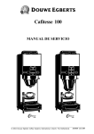
Cafitesse 100
SERVICE MANUAL
coffee
coffee
coffee
coffee
stop
espresso
© 2004 Douwe Egberts Coffee Systems International, Utrecht, The Netherlands
stop
35260400 July 2004
Copyright © All Rights Reserved. This manual may not be translated or copied or reproduced in any form
or by any means in whole or in part without the prior written consent of Douwe Egberts Coffee Systems,
Utrecht, the Netherlands.
This manual is intended for internal use only.
Douwe Egberts Coffee Systems issues no explanation or guarantees with regard to the contents of this
publication and expressly disclaims all responsibility for any implied guarantees. Douwe Egberts Coffee
Systems reserves the right to revise and change the contents of this manual without notice.
Published by Douwe Egberts Coffee Systems, Utrecht, the Netherlands
July 2004
© 2004 Douwe Egberts Coffee Systems International, Utrecht, the Netherlands
Service Manual Cafitesse 100
•
This Service Manual includes all Service Information sheets
until SI CFT 100/139.
07.2004
Preface / Safety Instructions
1
Installation / Putting into Operation
2
Faults
3
Programming
4
Functions
5
Water System
A
Brewing System
B
Dosing System
C
Product Delivery
D
Cooling System
F
Housing
G
Power Supply and Control System
K
External Options
L
Payment Systems
P
Preventive Maintenance
6
Service Procedures
7
Service Information
8
Modification Instructions
9
Spare Parts List
10
© 2004 Douwe Egberts Coffee Systems International, Utrecht, The Netherlands
Service Manual Cafitesse 100
Preface and Safety Instructions
Table of Contents
Preface and Safety Instructions
1
Preface/ How to use the manual
General
Structure of the Manual
Definition of Options and Accessories
1.1
1.1.1
1.1.2
1.1.3
Safety Instructions
1.2
07.2004
1-1
Service Manual Cafitesse 100
1
Preface and Safety Instructions
Preface and Safety Instructions
1.1 Preface/ How to use the Manual
1.1.1 General
•
This service manual is intended for trained
service technicians within the D.E.C.S.
organisation who have attended the product
training courses for this dispenser.
1-2
•
This service manual is not a study book
containing technical details about this
dispenser, but it can be considered and
used as a reference book.
07.2004
Service Manual Cafitesse 100
Preface and Safety Instructions
1.1.2 Structure of the Manual
•
Chapter
The service manual is divided into 10 sections
numbered from 1 to 10.
•
Subsections
Sections can be divided into subsections.
Section 5 is therefore divided into 9
subsections, each describing a special
function of the dispenser.
The description of the subsections (A, B,
etc.) matches the subsections used in the
Service Informations System (SIS) within
the D.E.C.S group .
•
Paragraph
Each subsection has the same paragraph
build up.
The water system serves as an example
and it can be found under:
Section
Subsection
Paragraph
5 Functions
A Water system
1 Adjustments
- This paragraph describes all possible adjustments for this
subsection, regarding timing, calibration etc.
2 (Dis)assemblies
- This paragraph describes in detail, how to assemble,
disassemble or exchange a particular component.
3 Functional descriptions
- This paragraph describes in detail how a particular
component of the dispenser works and how the different
parts in this system interact.
4 Electrical diagrams
- This paragraph describes the electrical input and ouput of
the water system.
5 Technical specifications
- This paragraph explains technical specifications of the water
system.
6 Options
- Available options, especially for the water system.
7 Accessories
- Accessories for the water system.
07.2004
1-3
Service Manual Cafitesse 100
•
•
Preface and Safety Instructions
When the dispenser was subject to
changes, consecutively numbered Service
Information sheets will inform you on these
changes. These are then to be filed as
chapter 8 in the Service Manual.
General information:
•
This manual is only valid for dispensers
with the Facelift Design or which have been
adapted accordingly.
Changes that must be carried out for each
dispenser available on the market will be
announced by Modification Instructions.
These are then to be filed as chapter 9 in
the Service Manual. After the modifications
have been carried out, the corresponding
number must be marked with a cross on
the Modification Record Sticker.
•
The concept of this manual has been
structured in order to be applicable for
several dispenser types. If a dispenser is
not equipped with a certain component, the
corresponding section is listed, but will be
blank. The complete numbering has not
been changed. Some paragraphs e.g. the
one on 'External Options' can be completed
by the service technician according to
requirements and country specifications.
1.1.3 Definition of Options and Accessories
•
Accessories and options are also described
in this Service Manual:
Definition
Description
Options
Various options for the dispenser result in different
versions, types or models of dispensers.
Example of options:
- Mixing unit
Functions within the
dispenser functions
(Chapter A.6)
Accessories
Additional components for the dispenser to allow other
functions or another appearance.
- Photographs frontside
- Photographs backside
- Drainage kit
- Side module
Functions within the
dispenser functions
(Chapter A.6)
External
Options
Arrangements that are not integrated into the dispenser.
They have a separate function regarding the dispenser.
Examples:
- Cooling device
- Water filter
- Water decalcifier
Information can be
found in subsection L.
1-4
07.2004
Service Manual Cafitesse 100
Preface and Safety Instructions
1.2 Safety Instructions
•
•
•
•
This subsection is intended as an overview
of the warnings and instructions used in
this manual, that must always be observed.
Hazard intensity levels
•
The following general safety precautions
apply to the operation and maintenance of
the dispenser, and must always be
observed. Non-observance of these
instructions or any other safety precautions
mentioned in this manual could impair the
dispenser's safety standards.
There are three different levels of hazard
intensity, identified by signal words – DANGER, WARNING and CAUTION. The level
of hazard is determined by the following
definitions:
DANGER
-
Sudden hazards, that WILL lead to either serious personal injury or death
WARNING
-
Hazards due to dangerous behavior that CAN lead to either serious injury or
death.
CAUTION
-
Hazards due to dangerous behavior that can lead to either minor injury to
persons or damage to product.
The dispenser must be placed on a table or
a counter. The dispenser can be used to
deliver hot beverages, such as coffee,
espresso, decaffeinated coffee or tea
(depending on the dispenser model). The
dispenser can be converted to deliver cold
beverages, such as café cool. The present
dispenser can only be used for liquid
beverage concentrate in one-way flexipacks. The manufacturer can not be held
responsible for dispensers, that were used
for purposes other than those specified in
this manual.
•
Service technicians must have read the
Service Manual and operating instructions
thoroughly, and understood both, before
they can install the dispenser and put it into
operation. The service technician must hand
over and explain the operating instructions
to the customer.
•
Installation/programming and repair of the
dispenser must be performed by trained
service technicians only.
The instructions in this manual must always
be followed. Non-observance can lead to
dangerous situations, and the manufacturer
cannot be held responsible for possible
damages.
07.2004
1-5
Service Manual Cafitesse 100
DANGER:
Never insert the power supply
plug of the dispenser into a
wet or damp socket. The plug
itself must not be wet or damp
either. Also never insert or
remove the plug from the
socket with wet hands.
DANGER:
The beverages delivered by the
dispenser are hot! To prevent
scalding, hands (and/or other
parts of the body) must be
kept away from the outlet area
while beverages are being
prepared and dispensed.
Preface and Safety Instructions
WARNING:
Check the drinking water
quality.
WARNING:
Keep children away from the
dispenser.
DANGER:
Safety devices must not be
bridged or put out of action.
DANGER:
The dispenser and the service
device are equipped with a
lithium battery.
1-6
The dispenser must be
connected to an electric circuit
which is secured by an extra
fuse.
We recommend the connection
to a supply with an integrated
fault current safety switch or
to install a fault current safety
switch. The connection must
be made using a safety plug
socket earthed according to
regulations.
Observe the local regulations!
WARNING:
There is a danger of an
explosion due to mishandling.
The battery may not be
recharged, disassembled,
short-circuited, burnt or
subject to temperatures above
100 °C or water. Replace it
only by a battery of the same
type. Spent batteries must be
disposed of properly.
The dispenser must be
connected to the drinking
water supply and to the
electric power supply in
accordance with the local
regulations.
If the dispenser is not used for
a longer period of time (e.g. at
night or during the weekend),
close the water tap. Set the
ON/OFF button to OFF.
The power supply may not be
interrupted completely,
because otherwise the cooling
system will not function any
more.
07.2004
Service Manual Cafitesse 100
Preface and Safety Instructions
WARNING:
If the dispenser is equipped
with a heating plate, do not
touch the heating plate. Danger of being burnt.
CAUTION:
The dispenser must not be
used when the water supply is
interrupted because the boiler
will not be refilled.
WARNING:
The dispenser must be cleaned
regularly for hygiene reasons
and to guarantee perfect
operation. Take care of sharp
edges when cleaning the
dispenser. Danger of scratches
or cuts!
CAUTION:
Do not switch off the
dispenser between beverage
deliveries in order to keep the
optimum water temperature in
the boiler.
CAUTION:
Only put heat-resistant glass
pots on the heating plate.
CAUTION:
Clean the inside and outside
of the dispenser by using a
damp cloth and do not splash
it. To clean the dispenser, only
use cleaning agents approved
by the food industry.
Never use high-pressure
sprays for cleaning.
CAUTION:
The use of the special
Cafitesse cleaning agent is
recommended. Do not pour
any water or cleaning agent
into the cooling compartment.
WARNING:
WARNING:
WARNING:
07.2004
For repair of the dispenser use
only original spare parts;
otherwise the manufacturer will
accept no liability in the event
of damage.
Only connect the dispenser to
the drinking water supply and
electric power supply in
accordance with all official
regulations and local
conditions.
Check if the current supply
matches the instructions of the
rating plate.
The dispenser is suitable for
indoor use only.
1-7
Service Manual Cafitesse 100
1-8
Preface and Safety Instructions
07.2004
Service Manual Cafitesse 100
Installation / Putting into Operation
Table of Contents
Installation / Putting into Operation
2
Transport/Handling
2.1
Installation Requirements
Tools
Water Supply
Electric Power Supply
Space Requirements
External Options
2.2
2.2.1
2.2.2
2.2.3
2.2.4
2.2.5
Unpacking
Unpacking the Dispenser
List of all Items that are supplied with the Dispenser
Disposal of Packaging and Dispenser
at the End of their Service Life
2.3
2.3.1
2.3.2
Installation / Putting into Operation
2.4
Checklist: Instructions for the Customer
2.5
Transfer of the Dispenser to the Customer
(incl. HACCP = Hazard and Critical Control Points)
2.6
Technical Data (Total Overview)
2.7
07.2004
2.3.3
2-1
Service Manual Cafitesse 100
2
Installation / Putting into Operation
Installation / Putting into Operation
2.1 Transport / Handling
•
Dimensions of the dispenser incl. packaging:
Height
Depth
Width
Weight
:
:
:
:
690 mm
535 mm
275 mm
21 kg
(27.17 in)
(21.06 in)
(10.83 in)
(46.3 lbs) (empty)
Transport in general
CAUTION: •
2-2
Transport the dispenser carefully.
•
Do not throw the dispenser or handle it incorrectly.
•
Do not transport several unfastened dispensers on top of each other.
•
Only transport the dispenser in upright position.
•
When storing the dispenser, ensure that it is only stored indoors and
take precautions against parasites.
•
Protect the dispenser from the influence of unusual odours.
07.2004
Service Manual Cafitesse 100
Installation / Putting into Operation
Transport due to location change
When transporting single dispensers,
use the handles supplied in the
package.
c o f f ee
c o f f ee
c o f f ee
stop
c o f f ee
stop
When transporting a used dispenser to a new
location:
c o f f ee
c o f f ee
•
•
•
•
•
•
Switch the main switch off and disconnect
the power supply plug.
Disconnect the dispenser from the water
supply.
Remove the flexi-pack.
Unhinge the floater wire over the float
switch.
Turn the thermostat to 0 position.
Drain the boiler.
WARNING:
•
•
c o f f ee
stop
c o f f ee
stop
Fig.1
Danger of being scalded by
hot water!
Pack the dispenser in such a manner that a
safe transport is guaranteed. Use the
original packaging if possible. (Fig.1, 2)
c o f f ee
c o f f ee
stop
c o f f ee
c o f f ee
When used dispensers are stored
intermediately for a long time, ensure that
the hose between the inlet valve and the
boiler is empty to avoid spoiling the taste.
stop
c o f f ee
c o f f ee
stop
c o f f ee
c o f f ee
stop
Original packaging by the manufacturer
•
European pallets (0.80 m x 1.20 m)
12 Cafitesse100 (max. 2 piles of 6
dispensers)
•
U.S. pallets (1.00 m x 1.20 m)
Special pallets made of wood treated
against parasites.
12 Cafitesse100 (max. 2 piles of 6
dispensers)
Fig. 2
Storage requirements
•
Ambient temperature: 5 °C - max. 32 °C
(41 °F - max. 90 °F)
07.2004
2-3
Service Manual Cafitesse 100
Installation / Putting into Operation
2.2 Installation Requirements
2.2.1 Tools
•
The following tools are required for installation.
Tool:
1. Service device
required for:
Programming
s
Part number
see spare parts list
e
rv
ic
e
d
e
v
ic
e
R
L
C
ck
lo
C
.
ep e
R od
C
t
u
p
In
2. Pressure gauge
Measuring the
water pressure
Part number
see spare parts list
3. Several
screw drivers
e.g.
adjustment of
voltage selector
Part number
see spare parts list
2-4
07.2004
Service Manual Cafitesse 100
Installation / Putting into Operation
2.2.2 Water Supply
Customer
Dispenser
Recommendation:
Water supply line with stop valve and nonreturn valve.
Connection to hot water line only with
suitable supply lines.
Connections for hoses:
R3/4''-3/8UNF USA/CAN
R3/4-R3/4 (Europe)
R3/4-R3/8 (The Netherlands)
Supply system
Temperature:
max. 75 °C (167 °F)
Dynamic pressure: min. 0.8 bar at 6 l/min.
(11.6 PSI at 1.32 UK gal/min/
1.59 US gal/min)
Static pressure:
max 10 bar (145 psi)
USA: The dispenser must be installed with
an adequate return flow protection that
complies with local regulations.
CAUTION:
Check the drinking water quality before the installation especially when
installing a tank for manual filling.
A drinking water filter is recommended.
CAUTION:
When using new water pipes, flush them sufficiently before the installation.
Read local regulations carefully when choosing supply lines. Only use neutral
material with respect to taste.
07.2004
2-5
Service Manual Cafitesse 100
Installation / Putting into Operation
2.2.3 Electrical Supply
Customer
Dispenser
Recommended: Fault current safety switch
and an all poles controlling contact breaking
device.
Requirements:
An earthed connection is required.
The mains connection must match the
dispenser output (socket).
Each dispenser must be protected.
National plug on power supply cable.
Length of the power supply cable approx.
1.80 m (71 in)
Water connection
Fuses
Power supply cable
Fig. 1 Dispenser Connections
2-6
Water outlet
(e.g. drainage kit)
07.2004
Service Manual Cafitesse 100
Installation / Putting into Operation
Dispenser Types (Mains Voltage)
Voltage
Heating
capacity Type *
Country
Approval
100 Volt,
1.4 kW
A-12-F
Japan
–
120 Volt,
1.4 kW
A-08-F(B)
USA
UL, CSA, NSF
200 Volt,
3.0 kW
A-13-F
Japan
Radio protect
200 Volt,
3.0 kW
A-14-F
Japan
Radio protect
220 Volt,
3.0 kW
B-60-F(B)
Korea
VDE, CE
without counter/
230 Volt,
2.0 kW
B-05-F(B)
Scand.
VDE, CE
key switch
230 Volt,
3.0 kW
B-58-F(B)
Israel
VDE, CE
230 Volt,
3.0 kW
B-39-F(B/U) Europe
VDE, CE
208-240 Volt, 3.0 kW
A-07-F(B)
USA
UL, CSA, NSF
208-240 Volt, 3.0 kW
A-17-F(B)
Mexico
UL, CSA
240 Volt,
2.7 kW
B-03-F(B)
UK/Austr. VDE, CE
230 Volt,
2.0 kW
B-10-F(B/U) Scand.
230 Volt
2.0 kW
B-55-F(B)
Germany VDE, CE
with counter/
230 Volt,
3.0 kW
B-15-F(B)
Netherl.
key switch
230 Volt,
3.0 kW
B-31-F(B)
Germany VDE, CE
240 Volt,
2.7 kW
B-41-F(B)
GB
VDE, CE
100 Volt,
1.4 kW
A-21-F
Japan
VDE, CE
200 Volt,
3.0 kW
A-19-F
Japan
–
220 Volt,
3.0 kW
B-59-F(B)
Korea
VDE, CE
without counter/
230 Volt,
2.0 kW
B-50-F(B)
Scand.
VDE, CE
key switch
230 Volt,
3.0 kW
B-38-F(B/U) Europe
VDE, CE
Cafitesse 110
VDE, CE
VDE, CE
208-240 Volt, 3.0 kW
A-20-F(B)
Caribbean VDE, CE
208-240 Volt, 3.0 kW
A-18-F(B)
Mexico
240 Volt,
2.7 kW
B-46-F(B)
UK/Austr. VDE, CE
230 Volt,
2.0 kW
B-47-F(B)
Switzerl.
with counter/
230 Volt,
2.0 kW
B-56-F(B)
Germany VDE, CE
key switch
230 Volt,
3.0 kW
B-40-F(B)
Europe
230 Volt,
3.0 kW
B-53-F(B)
Germany VDE, CE
UL, CSA
Cafitesse 120
*
VDE, CE
VDE, CE
The additional letter B (e. g.: SATA07FB) indicates dispensers with 'Douwe Egberts' branding
stickers. (see chap. 10)
The additional letter U (e. g.: SATB39FU) indicates dispensers with 'Universal' branding stickers.
(see chap. 10)
07.2004
2-7
Service Manual Cafitesse 100
Installation / Putting into Operation
2.2.4 Space Requirements
645mm (25.39 in)
Space requirements
when the cooling compartment lid is closed:
50mm
(1.97 in)
Flexipack
1075mm (42.32 in)
120mm
(4.72 in)
400mm(15.74 in)
Space requirements
when the cooling compartment lid is open:
455mm (17,91 in)
455mm(17.91 in)
210mm
(8.27 in)
Plan view:
Minimum requirements for floor, walls and ceilings in the area of the dispenser:
Floor
Walls
Ceiling
2-8
: Even, nonskid floor
: There are no particular requirements for walls since the dispenser is not designed
for wall mounting.
: Dustfree, clean
07.2004
Service Manual Cafitesse 100
Installation / Putting into Operation
2.2.5 External Options
(to be used by Opcos and distributers for national information (e.g. via external
filters))
07.2004
2-9
Service Manual Cafitesse 100
Installation / Putting into Operation
2.3 Unpacking
2.3.1 Unpacking the Dispenser
•
Remove the fastener from the cardboard
box carefully. Do not use sharp utensiles to
avoid scratching the dispenser.
•
Remove the cardboard box clamps.
•
Open the cardboard box and cut it carefully
if necessary.
•
Pull the dispenser with the styrofoam
packaging out of the cardboard box and
place it upright.
•
Remove the styrofoam packaging.
•
Check if all mounting kits are included (see
below).
2.3.2 List of all Items that are supplied with the Dispenser
Description
Included in:
Operating instructions
Cooling compartment sticker
Cleaning card
Cleaning brush
Buttons
Connecting pieces for water inlet
Electric diagram
Keys3 (2 pieces)
Sticker, control card
Cup carrier
Country kit1
Country kit1
Country kit1
Country kit1
Partly in country kit1 (depending on the country)
Cooling compartment2
Inner side of the back wall
Dispenser
Cooling compartment
Cooling compartment
1
2
3
2 - 10
stand alone packaging unit
country specific, partly included in the country kit
key switch available with this version
07.2004
Service Manual Cafitesse 100
Installation / Putting into Operation
2.3.3 Disposal of Packaging and Dispenser at the End of their Service Life
Used packaging:
Packaging
Material*
Outer cardboard box
Cardboard **
Inner packaging
EPS***
*
Disposal of material must always be done in accordance with
- national,
- legal,
- safety requirements and
- environmental requirements!
**
Composition:
Liner
Fluting paper
Inner paper
2
: Kraft liner, GSM substance 150g/m , marbled colour
2
: Wave substance, GSM substance 105g/m , brown colour
2
: Duplex, GSM substance 170g/m , brown colour
*** Styrofoam-polystyrene with pentane (CFC-free)
07.2004
2 - 11
Service Manual Cafitesse 100
Installation / Putting into Operation
2.4 Installation / Putting into Operation
•
Before starting the installation:
- Observe the specifications on the rating
plate (on the left side of the housing)
- Check the monophase plug and ensure
that national voltages and tolerances are
provided.
- Ensure that the fuse of the group to
which the dispenser is connected is in
accordance with the national regulations.
- Contact the local power supply company
to ask for the voltage values and
tolerances if required.
- Measure the water pressure.
- Measure and check the power voltage.
1
3
4
5
6
TYP
WITTENBORG
MADE IN DENMARK
2
SAT A08F
NR.
120
V~
TOTAL
1,6
kW
KÜHLUNG, REFRIGERATION
REFROIDISSEMENT
W
HEIZUNG, HEATING
CHAUFFAGE
1,4
kW
COMPRESSOR, COMPRESSEUR
A
1,4
A
KESSELINHALT, BOILER CAP,
CAPACITÉ DE LA BUILLOIRE
l.
BETRIEBSDRUCK, OPERATING PRESSURE
PRESSION DE SERVICE
ATM
HÖCHSTZUL. DRUCK, MAXIM. PRESSURE
PRESSION MAXIMUM
HZ / CPS
bar
bar
N&W Global Technology
8
Fig. 1
•
109711113882185
VOLT
7
Legend of the rating plate
(Example fig. 1):
1
Machine type
2
Machine number
3 - 6 Electric connection values
7
Water pressure indications
8
Approval
Measuring the water pressure
(not concerning the water tank version)
•
Static and dynamic pressure can be
checked by using the water pressure
measuring device which is available as a
service part. (Fig. 2).
•
Pressure should be checked under the
most unfavourable conditions, e.g. when all
remaining power consuming locations are
opened (dynamic) and when all are closed
(static).
•
Connect the pressure gauge to the water
pipe with a pressure hose and one of the 4
connections A, B, C or D which are
supplied with the testing device. It is also
possible to use the hose which serves for
connecting the dispenser later.
•
Close the water tap located on the pressure
testing device and open the stop valve in
the water pipe completely.
•
Position the outlet above a container and
open the tap. Read the dynamic pressure
on the pressure gauge. The pressure
should always be over 0.8 bar (11.6 psi).
2 - 12
If the outlet needs to be extended, use
a hose with an interior diameter of at
least 15 mm (0.59 in).
•
Close the tap and read the static line
pressure on the pressure gauge. The value
should be less than 10 bar (145 psi).
•
Close the stop valve of the water pipe. Remove
the water pressure measuring device and
connect the dispenser to the water supply.
•
Ensure that the water stop valve connected to
the supply line seals properly.
A
B
C
D
Fig. 2
07.2004
Service Manual Cafitesse 100
•
Installation / Putting into Operation
The dispenser may be installed on a flat,
even counter, table, base stand or on a
wall-mounted table.
4
1
3
•
If there are no even installation surfaces,
the dispenser must be aligned.
•
A minimum clearance of 5 cm (1.97 in)
must be maintained at the back panel of
the dispenser to ensure enough cooling.
•
2 packagings are supplied:
5
1. Standard dispenser
2. Country kit with national accessories.
•
Measure the water pressure (see chap. 2.4).
•
Measure the supply voltage.
•
Unpack the dispenser (see chap. 2.3).
xx
•
Place the dispenser on a table.
•
Remove the operating panel cover (1), the
front cover (2), the housing cover (3) with
cooling compartment lid (4) and air duct (5)
(Fig. 3).
CAUTION:
When the front cover is made
of glass, there is the danger of
being injured due to incorrect
handling or breaking of the
glass.
•
Adhere the cooling compartment sticker of
the country kit on the inside of the cooling
compartment lid (4) (Fig. 3).
•
Lift the floater wire (7) from transport
position and place it above the operating
lever (6) of the float microswitch (Fig. 4).
xx
x
xx
xx
xx
xx
xx
ST
OP
2
Fig. 3
6
7
Fig. 4
07.2004
2 - 13
Service Manual Cafitesse 100
•
Installation / Putting into Operation
Ensure that the thermostat (1) is turned
counterclockwise to zero (until stop) (Fig. 5).
CAUTION:
If the thermostat is not turned
to zero, the dispenser will heat
and the capillary tube limiter
will be released.
1
Fig. 5
•
Dispensers designed to be operated with
208-240 V 60 Hz (USA/Canada) are
equipped with a voltage selector located on
the back panel of the dispenser (Fig. 6).
•
Adjust the voltage selector (2) before
connecting the dispenser to adapt the
dispenser to the mains voltage (Fig. 6).
•
For the adjustment loosen the fuse holder
and turn the adjusting bush (3) by means
of a screwdriver until the marking arrow
points to the correct voltage mark (Fig. 6).
2 - 14
3
2
Fig. 6
07.2004
Service Manual Cafitesse 100
•
Insert both lower buttons (1) (Fig. 7).
•
Leave the upper button (2) free for
programming (Fig. 7).
Installation / Putting into Operation
2
Set the key to ON with dispensers
equipped with a key switch.
•
Mount the cup carrier (3) (Fig. 8).
•
Connect the water supply and open the
water stop valve in the water pipe.
•
Insert the power supply plug.
•
Switch on the main switch. Water should
now flow into the boiler.
Observe if the floater switches off.
•
The fan must now be operating to cool the
cooling compartment. The yellow LED (4)
extinguishes as soon as the cooling
compartment has reached the correct
temperature. (Fig. 8)
xx
xx
x
1
ST
OP
Fig. 7
4
xxxxx
•
Place a container below the hot water
delivery tap (5) at the front of the dispenser
and open the tap. (Fig. 8)
Observe if the boiler is being refilled with
water at the same time.
WARNING:
There is the danger of being
scalded by hot water. Keep
hands and other parts of the
body away from the delivery
area.
•
Observe the floater wire (6) during the
filling process. In the beginning the floater
wire (6) should fall down and then rise.
This indicates that water is running into the
boiler faster than it is taken from it. (Fig. 9)
•
Stop actuating the hot water delivery tap to
allow the boiler to be filled completely.
Observe again if the floater wire switches
off.
OFF
ON
STOP
xxxxx
5
3
Fig. 8
6
Fig. 9
07.2004
2 - 15
Service Manual Cafitesse 100
•
Turn the thermostat regulator (7) clockwise
up to the stop, to the maximum
temperature of 95 °C (171 °F). (Fig. 10)
•
Ensure that the dispenser heats up and is
switched off. (Low temperature indicator (8)
extinguishes.). (Fig. 11)
•
In this case switch off the main switch (9)
of the dispenser, and disconnect the power
supply plug (Fig. 11).
•
Mount the back panel, the air duct and the
housing cover with the cooling compartment
lid.
•
Remove the foil from the front cover and
the splash panel.
•
Insert the advertising panel and the front
cover (10/11). (Fig. 11)
CAUTION:
•
When the front cover is made
of glass, there is the danger of
being injured due to incorrect
handling or breaking of the
glass.
Degrease the housing wall thoroughly at
which the card holder (12) is to be
installed. (Fig. 11)
Installation / Putting into Operation
7
Fig. 10
10/
11
12
8
xxxxx
•
For degreasing, it is recommended to use a
mixture of 50% isopropanol and 50% water.
•
Mount the card holder (12) to the
dispenser. (Fig. 11)
•
Insert the documents into the card holder.
CAUTION:
The last page of the Quick
Reference card (Cleaning Report)
has to be copied, has to be filled
in by the trained Cleaning Personal and has to be filed up.
•
Connect the power supply plug again.
•
Switch the dispenser on at the main switch
(9). (Fig. 11)
•
Programme the dispenser in accordance
with the customer's demands (see chap. 4).
Factory settings: see chap. 4.
OFF
ON
STOP
xxxxx
9
OFF
ON
POWER
Fig. 11
2 - 16
07.2004
Service Manual Cafitesse 100
The bush (1) for the service device is
located behind the upper button. Insert the
upper button (Fig. 12).
•
Place a container below the hot water
delivery tap.
•
Let at least 6 l (1.32 UK gal/1.58 US gal)
of water run through the boiler by actuating
the hot water delivery tap in order to rinse
the boiler (Fig. 8).
WARNING:
•
There is the danger of being
scalded by hot water. Keep
hands and other parts of the
body away from the delivery
area.
Remove the protective foil from the splash
panel before putting the dispenser into
operation.
•
Insert the flexi-pack.
•
Carry out a functional check of the
dispenser.
•
Hand over the operating instructions to the
customer.
•
Installation / Putting into Operation
1
xx
xx
x
ST
OP
Fig. 12
2
5
7
6
3
4
Instruct the customer how to operate the
dispenser.
Fig. 13
Remark regarding the cup carrier:
•
The turn lift support (2) can be attached to
the right side of the dispenser if necessary.
In this position the cup carrier (7) is turned
to the right side during the filling of pots.
(Fig. 13)
•
To remove the support, pull the torsion
spring (3) downwards and withdraw the
support pin (4) from the bottom side of the
drip tray support. (Fig. 13)
•
Remove the dummy plugs (5, 6) and install
the turn lift support (2) on the right
(Fig. 13).
The tension of the torsion spring can be
changed. Adjust the tension of the torsion
spring in such a manner that the turn lift
support does not rebound when it is locked.
(Fig. 14)
•
Mount the dummy plugs (5, 6) to the left
side. The cup carrier locks when it is
turned towards the right side (Fig. 13).
•
Adjust the height of the cup carrier (for the
delivery of cups). (Fig. 15)
A
B
Fig. 14
Fig. 15
07.2004
2 - 17
Service Manual Cafitesse 100
Installation / Putting into Operation
Putting the dispenser into operation on ferries
•
Dismount the overflow hose (1) provided by
the manufacturer. (Fig. 1)
•
Cut 365 mm (14.37 in) off from the hose
(piece goods).
•
Directly connect the boiler overflow
chamber (4) and the outlet of the overflow
tray (3) to the new hose (2). (Fig. 1)
•
Connect the outlet hose.
A table fixing is not provided by the
manufacturer. However, it is urgently
recommended depending on the local
conditions.
WARNING:
4
1
2
The dispenser only operates
up to the following maximum
tilts:
Tilt to the left and front:
each 12°, i.e. 130 mm (5.12 in)
Tilt to the right and to the rear
each 10°, i.e. 110 mm (4.33 in)
WARNING:
There is the danger of being
scalded by hot water. Keep
hands and other parts of the
body away from the delivery
area.
•
If the tilts exceed these values
- the water supply must be closed
- the dispenser must be switched off with
the main switch
- the boiler must be drained via the hot
water delivery tap
(place a sufficiently large container
underneath the hot water delivery tap)
•
If the tilt decreased again below the above
mentioned values:
- open the water supply
- switch the dispenser on.
2 - 18
3
Fig. 1
07.2004
Service Manual Cafitesse 100
Installation / Putting into Operation
2.5 Checklist: Instructions for the Customer
07.2004
2 - 19
Service Manual Cafitesse 100
Installation / Putting into Operation
2.6 Transfer of the Dispenser to the Customer
(incl. HACCP= Hazard and Critical Control Points)
2 - 20
07.2004
Service Manual Cafitesse 100
Installation / Putting into Operation
2.7 Technical Data (Total Overview)
Dimensions:
Height: 645 mm (25.39 in) (C110/C120)
Width: 210 mm (8.27 in)
Depth: 455 mm (17.91 in)
Weight:
21 kg (46.3 lbs) (empty)
Water connection*:
3/4'' connection to inlet valve
Drinking water line with stop valve.
Connection to warm water line only with matching feedings
Supply system requirements:
Water inlet temperature:
max. 75°C (167°F)
Dynamic pressure:
min. 0.8 bar at 6 l/min(11.6 psi
at 1.32 UK gal/min/1.59 US gal/min)
Static pressure:
max. 10 bar (145 psi)
Tank top version:
Capacity:
Tank on the dispenser for manual filling.
4 l (0.88 UK gal/1.06 US gal)
Cold water connection
for café cool (option):
Dynamic pressure:
Static pressure:
min. 0.8–4 bar at 1.2 l/min(11.6-58.02 psi
at 0.26 UK gal/min/0.32 US gal/min)
max. 7 bar (101.53 psi)
Water filling amount:
6.5 l (atmospheric boiler) (1.43 UK gal/1.72 US gal)
Concentrate capacity:
Coffee and tea flexy-pack with 2 litres contents each
(0.44 UK gal/0.53 US gal)
Electrical
Connection values:
Tolerance
Voltage
100
120
200
230
230
230
240
240
+/-10 %
+/-6 %
+/-10 %
+6 %/-10 %
+6 %/-10 %
+6 %/-10 %
+/-6 %
+/-6 %
V
V
V
V
V
V
V
V
Heat capacity
(over- and
undervoltage)
1.4 kW
1.4 kW
3.0 kW
2.0 kW
2.7 kW
3.0 kW
3.0 kW
2.7 kW
Total output
1.6
1.6
3.2
2.2
3.0
3.2
3.2
2.9
kW
kW
kW
kW
kW
kW
kW
kW
Electric connection:
A fuse must be provided in the mains supply line
Length of power
supply cable:
approx. 1.80 m (70.87 in = 5.9 ft)
The dispenser is delivered with national power supply cable.
07.2004
2 - 21
Service Manual Cafitesse 100
Installation / Putting into Operation
Boiler:
Open system, filling capacity 6.5 l (1.43 UK gal/1.72 US gal)
electromechanical water temperature regulator,
dry running protection (supervision by means of heating element
temperature limiter, electronic low temperature indicator/boil over sensor,
boil over protection by means of safety thermostat)
Boil over sensor:
Triggering temperature:
Triggering temperature > 2000 m (6561.68 ft):
Beverage
delivery capacity:
approx. 300 cups/hour at 230 V/3 kW
or approx. 200 cups/hour at 230 V/2 kW
Cooling:
Thermoelectric cooling: Peltier element, axial blower
electronic control, pulse-mode operation
power consumption approx. 40 W (without fan).
Dosing systems:
Pulse dosing system, dosing coil electronically controlled, pulse operated
pump integrated with non returnable concentrate pack, electronic
concentrate empty indicator.
Delivery modes:
Adjustable delivery mode, size of a portion and beverage strength
delivery modes: portioned, portion repetition or continuously (see
programming) outlets, delivery tap for permanent hot water delivery
Further requirements
for installation:
Height:
Ambient temperature:
Distance to wall:
90 °C - 8 K (164 °F)
85 °C - 8 K (155 °F)
up to 2000 m (6561.68 ft)
5°–max. 32 °C (41°–max. 89.5 °F)
50 mm (2 in) (rear of the dispenser)
The dispenser is drip-proof and is suitable for indoor use only.
Approvals see there.
2 - 22
07.2004
Service Manual Cafitesse 100
Faults
Table of Contents
Faults
3
Support for Fault Diagnosis
3.1
Fault Diagnosis
General Malfunctions
Water System Malfunctions
Cooling System Malfunctions
Dosing System Malfunctions
Heating Plate Malfunctions (Option)
Key Switch/Counter Malfunctions (Option)
Indicated Malfunctions
3.2
3.2.1
3.2.2
3.2.3
3.2.4
3.2.5
3.2.6
3.2.7
Faults occurred in the Market and their Solutions
3.3
07.2004
3-1
Service Manual Cafitesse 100
3
Faults
Faults
3.1 Support for Fault Diagnosis
Step
if yes
if no
1
Ask customer for detailed information
about malfunction and backgrounds
2
Are the malfunctions displayed on the
dispenser? Which displays?
see 3.2
see 3.2 or
perform step 3
3
Is the problem described in 3.3?
proceed as
described in 3.3
perform step 4
4
Is the current supply okay?
perform step 5
see 3.2
5
Is the DC supply okay?
perform step 6
see 3.2
6
Is the water supply okay?
perform step 7
see 3.2
7
Are the flexy-packs inserted correctly
and full?
see 3.2
see 3.2
3-2
07.2004
Service Manual Cafitesse 100
Faults
3.2 Fault Diagnosis
General:
•
DANGER:
Never insert the power supply
plug of the dispenser into a
wet or damp socket. The plug
itself must not be wet or damp
either. Also never insert or
remove the plug from the
socket with wet hands.
DANGER:
The dispenser and the service
device are equipped with a
lithium battery.
The list of possible faults and the appropriate
trouble shooting is divided into two main groups:
- Faults, which are not indicated, but which
can be localised due to particular
malfunctions of the dispenser,
- faults, which are indicated via LEDs and/
or displayed on service device 2.
- yellow LED OFF: correct water
temperature in the
boiler and in the cooling
compartment
yellow LED
constantly ON:
water temperature in
the boiler too low.
Correct cooling
compartment
temperature
- yellow LED
flashes (short
flash frequency): correct water
temperature in the
boiler. Incorrect cooling
compartment
temperature
- yellow LED
flashes (long
flash frequency): water temperature in
the boiler too low.
Incorrect cooling
compartment
temperature
•
•
Some faults are indicated by LEDs which
are flashing either individually or in
combination with other LEDs.
The fault diagnosis takes precedence over
the normal display function.
Fault localisation
•
Connect the service device and switch it on.
•
Switch off the main switch of the dispenser.
Resetting the fault display after repair work
•
There is the danger of an
explosion due to mishandling.
The battery may not be
recharged, disassembled,
short-circuited, burnt or
exposed to temperatures
above 100 °C or water.
Replace it only with a battery
of the same type. Spent
batteries must be disposed of
properly.
DANGER:
Safety devices must not be
bridged or put out of
operation.
WARNING:
Use only original spare parts
when repairing the dispenser;
otherwise the manufacturer
cannot be held liable.
WARNING:
If the dispenser is equipped
with a heating plate, do not
touch the heating plate. There
is the danger of being burnt.
CAUTION:
It is provided that the control
system has been programmed in
accordance with the dispenser's
requirements. The following list
of possible faults does not
consider any programming
errors.
Therefore it is recommended
to check the programming of
the control system first by
means of service device 2
before carrying out any trouble
shooting according to the
following chapter.
Disconnect the power supply plug.
DANGER:
07.2004
The beverages delivered by the
dispenser are hot! To prevent
scalding, keep hands (and/or
other parts of the body) away
from the beverage outlet area
when beverages are prepared
and during the functional test.
3-3
Service Manual Cafitesse 100
Faults
3.2.1 General Malfunctions
Fault
Possible cause
Remedy
The dispenser does
not operate
1. Connections to the power
supply or power supply
plug are unplugged
1. Check connections.
If not ok: Connect supply lines
correctly.
2. Mains fuse blown
2. Insert correct fuse.
Check voltage of power supply socket
with voltmeter.
If the fuse blows again, the fault may
concern either heating (ground short
circuit), power supply (transformers),
or damage caused by water. When
mounting the dispenser: Check if the
dispenser heating capacity exceeds
that of the local supply network –>
replace the dispenser.
1. Main switch OFF
1. Switch the dispenser on.
2. Main switch defective
2. Check the connections of the switch.
If the connections are okay, replace
the switch.
1. Fuse F05 of power supply
defective
1. Check connection of the fuse F05
with multi-meter (adjust to Ohm).
If no connection: Replace the fuse.
2. Defective transformer T02
2. Check the output for 25 V alternating
voltage (see chap. 5K - Electric
Diagramm).
If not 25 V: Replace the transformer.
3. With dispensers equipped
with voltage selector:
Voltage selector adjusted
incorrectly or defective
3. Adjust the voltage selector to mains
voltage or replace it.
4. Defective control unit
4. Replace the control unit (see chap.
5K.2).
5. Key switch "off"
5. Position the key switch to "on".
1. Control unit defective
1. Replace the control unit
(see chap. 5K.2).
2. Stop button defective
2. Replace the stop button.
3. Cable harness defective
3. Check the cable harness for
transmission.
If no transmission: Replace the cable
harness.
No dispenser
function except for
cooling system
No function except
for cooling system
and heating
No STOP function
3-4
07.2004
Service Manual Cafitesse 100
Faults
3.2.2 Water System Malfunctions
Fault
Possible cause
Remedy
Water runs from
overflow when
dispenser is
switched on
1. Float guide is blocked due
to calcification
1. Decalcify the boiler.
2. Float switch defective
2. Check the water inlet valve for 25 V
alternating voltage when the float
switch arm is completely lifted.
If 25 V: Replace the float switch.
3. Inlet valve does not close
3. Replace the inlet valve.
Also on installation: Rapidly open and
close the water tap several times, in
order to achieve easy operation of the
valve after possible long storage
(dynamic pressure).
Water runs from
overflow when
dispenser is
switched off
1. Inlet valve defective
1. Replace the inlet valve
(see chap. 5A.2).
Water leaks from
trough
1. Trough is calcified: outlet
valve tappet does not seal
1. Dismount and clean the tappet.
Decalcify the boiler (see chap. 5A.2).
2. Tappet lip seal damaged
2. Replace the lip seal.
3. Ventilating hose in outlet
elbow blocked or bent
3. Clean or replace the hose.
1. O-ring of outlet elbow
damaged or elbow
deformed
1. Replace O-ring/elbow
(see chap. 5A.2).
2. Supporting ring overturned
2. Replace the boiler if the locking
mechanisms at the outlet are
destroyed.
1. Outlet valve tappet
blocked
1. Dismount and clean the tappet.
Decalcify the boiler (see chap. 5A.2).
Water leaks from
drain valve
Dispenser delivers
concentrate but no
water.
Boiler filled
07.2004
3-5
Service Manual Cafitesse 100
Faults
Fault
Possible cause
Remedy
The dispenser
delivers concentrate
but no water.
Boiler empty
1. Main valve in the water
pipe is closed
1. Open the main valve.
2. Pipe is blocked or supply
insufficient
2. Check the pipe pressure with water
pressure measuring device. Open the
water tap completely. If the water
pressure is less than 0.8 bar
(11.6 psi), the dispenser does not
operate.
3. Floater washer is blocked
due to calcification
3. Decalcify the boiler.
4. Inlet valve filter is blocked
4. Dismount and clean the filter.
5. Float switch is defective
5. Check the inlet valve for 25 V
alternating voltage when the float
switch arm is completely depressed.
If 25 V: Replace the switch.
6. Inlet valve coil is defective
6. Check the coil for 25 V alternating
voltage.
If 25 V: Replace the valve
(see chap. 5A.2).
1. Water level in the boiler
varies, supply is
insufficient
1. Check the flow rate. Check whether the
pipe is blocked. Open the water tap
completely. If the water pressure is less
than 0.8 bar (11.6 psi), the dispenser does
not operate.
2. Control defective
2. Replace the control (see chap. 5K.2).
3. Outlet valve is calcified
3. Clean the outlet valve.
Water is dripping
from the hot water
tap
1. Tap calcified or seal
defective
1. Clean the tap or replace the seal.
Dispenser does not
heat up the water
1. Power switch off
1. Switch on the dispenser.
2. Thermostat off (–> dry
running protection)
2. Adjust the thermostat.
Reset the dry running protection.
Irregular water
supply
If the boiler is not filled
completely:
3-6
3a Main valve in the water
pipe is closed (–> dry
running protection)
3a Open the main valve.
Reset the dry running protection.
3b Pipe is blocked or supply
insufficient (–> dry running
protection)
3b Check the pipe pressure by means of a
water pressure gauge. Open the water tap
completely. If the water pressure is less
than 0.8 bar (11.6 psi) the dispenser does
not operate.
Reset the dry running protection.
07.2004
Service Manual Cafitesse 100
Faults
Fault
Possible cause
Remedy
The dispenser does
not heat up the
water
4. Defective thermostat
4. Check the connection with maximum
adjustments. If no connection:
Replace the thermostat (see chap.
5A.2).
5. Contacts of temperature
limiter open or defective
(–> dry running protection)
5. Press Reset button. Check the
connection. If no connection:
Replace the temperature limiter.
Reset the dry running protection.
6. Contacts of overflow
safety thermostat open
6. Sensor tube calcified or
reset the thermostat to zero (•) and
check the connection.
Decalcify the boiler
or
if connecting: Replace the thermostat,
reduce the adjustment of the
thermostat if required.
Press Reset button.
7. Defective heating element
7. Check the heating element for
connection and short circuits, replace
the heating element if required (see
chap. 5A.2).
1. Thermostat switches off
too late – lime deposits in
sensor tube
1. Decalcify the boiler.
2. Thermostat adjustment is
higher than required
2. Reduce the adjustment.
3. Thermostat contacts are
fixed
3. Reset the thermostat to zero (•) and
check for connection, replace the
thermostat if required.
1. Defective LED, control unit
or sensor
1. Disconnect the sensor plug ST04
from the control and bridge PINs 1
and 2 of BU04.
Water boils
(steam)
Low temperature
indicator does not
operate
LED flashing: Defective sensor —>
Replace the sensor.
LED not flashing: Defective LED or
control unit —> Replace LED —>
LED not flashing: Replace the
control unit.
Yellow LED flashing
(long flashing
frequency)
Delivery blocked
07.2004
1. Water temperature in
boiler <80°C (176°F)
and 'Temp block=ON'
1. Wait until the water in the boiler has
reached delivery temperature again.
If the LED does not stop flashing, see
'The dispenser does not heat up the
water'
3-7
Service Manual Cafitesse 100
Faults
3.2.3 Cooling System Malfunctions
Fault
Possible cause
Remedy
Yellow LED on
operating panel is
flashing (short
flashing frequency),
insufficient cooling.
Temperature >11 °C
(51 °F)
1. Power supply interrupted
or dispenser disonnected
from the mains supply for
a longer time
1. Check the power supply. The flashing
stops as soon as the correct
temperature has been reached (after
approx. 1 hour).
2. Flexy-packs' temperature
too high, was not thawed
in the refrigerator
2. Replace the flexy-pack, follow filling
and thawing requirements.
3. Ventilating grid blocked
3. Clean. Place the dispenser with a
distance to the wall of at least 5 cm
(2 in).
4. Heat sink or fan blocked
4. Clean.
5. Fan defective
5. Replace the fan (see chap. 5F.2).
6. Ambient temperature too
high
6. Change the location of the dispenser.
7. Wrong tolerance of the
Peltier element
7. Disconnect sensor plug ST05 from
the control unit and bridge PINs 1
and 2 of BU05. Measure the voltage
above the multiplier. If the measured
value is out of tolerance 0.1V <
value < 0.32V: Replace the Peltier
element.
The cooling system
does not run, the
yellow LED on the
control system is
off
1. Break down of the fuse
F04 in the power supply
or of thermo fuse in the
transformer T01 (USA/
Can)
Transformer T01 or
control unit defective
1. Disconnet plug ST07 from the control
unit, replace the fuse, and check
transformer T01 for 11-14V at PIN 5
and 2 (see chap. 5K.2).
If 11-14V: Replace the control unit.
If not 11-14V: Replace transformer
and fuse.
The cooling system
does not run, the
yellow LED on the
control system is on
1. Temperature sensor or
control unit defective
1. Disconnect sensor Bu05 from the
control unit. Check if Bu06 carries
12 V at PIN 1 and 3.
If 12V: Replace the pipe.
If not 12V: Replace the control unit.
2. Peltier element defective
2. Disconnect the sensor plug ST05
from the control unit and bridge PINs
1 and 2 of BU05. Measure the
voltage above the multiplier. If the
measured value is out of the
tolerance 0.1V < value < 0.32V
:
Replace the Peltier element (see
chap. 5F.2).
3-8
07.2004
Service Manual Cafitesse 100
Faults
Fault
Possible cause
Remedy
Yellow LED at
operating panel
flashes (short
flashing frequency),
excessive cooling.
Temperature below
0°C (32°F)
1. Control unit or
temperature sensor
defective, detached (no
contact) or short circuit
due to humidity.
1. Replace the sensor. If not remedied,
replace the control unit (see chap.
5K.2).
3.2.4 Malfunctions Dosing System
Fault
Possible cause
Remedy
Dispenser does not
deliver beverages
1. Empty flexy-pack (indicator
'empty' on)
1. Change the flexy-pack.
2. Dispensers equipped with
key switch: Switch is off
or defective
2. Switch on or replace the switch.
3. Connections of delivery
button or button defective
3. Check the wiring.
If o.k., check conduction of the
switch.
If not o.k.: Repair the wiring.
If no conduction of the switch:
Replace the switch.
4. Defective fuse F05 at
power supply
4. Replace the fuse.
5. Defective transformer T02
5. Check the output for 25V AC.
If not 25V: Replace the transformer.
6. Incorrect setting of voltage
selector or defective
voltage selector
6. Set the voltage selector according to
mains voltage or replace the voltage
selector.
7. Defective control unit
7. Replace the control unit (see Chap.
5K.2).
07.2004
3-9
Service Manual Cafitesse 100
Faults
Fault
Possible cause
Remedy
Beverage strength
varies, irregular
concentrate dosing
1. Ventilation hose in the
outlet elbow is blocked or
bent
1. Decalcify or adjust the hose.
2. Dosing system of flexypack defective
2. Replace the flexy-pack.
3. Intervals of dosing pulses
out of tolerances
3. Check if message "ERROR-last
dosing" is displayed by means of
service device 2. If no ERR is
displayed, proceed with step 4.
If ERR is displayed, proceed with 3a.
3a Dosing system of flexypack or flexi-pack
incorrectly inserted
3a If not o.k., insert the flexy-pack in
accordance with instructions.
3b Error of control unit
3b Replace the control unit (see chap.
5K.2).
4. Conduction through
concentrate coil out of
tolerances
4. See step 3.
5. Water level in the boiler
varies, insufficient supply
5. Check the flow rate, check whether
the supply line is blocked.
6. Control unit defective
6. Replace the control unit (see chap.
5K.2).
1. Incorrect insertion of flexypack
1. Insert the flexy pack-in accordance
with instructions, insert a new
package if necessary.
2. Transistor, diode in
screened coil, or control
unit defective
2. Disconnect ST08 from control unit.
Check LED.
If LED flashes: Replace the control
unit.
If LED does not flash: Replace
diode/transistor.
Check the 'empty' indicator and
replace it if necessary.
1. LED, phototransistor,
photodiode, or control unit
defective
1. Bridge PINs 1 and 4 of Bu/St08:
Check LED.
If LED flashes: Defective transistor or
diode —> replace. If LED does not
flash: Defective control unit —>
replace.
Defective LED —> replace LED.
"Empty" indicator
on, flexy-pack full
"Empty" indicator
off, but flexy-pack
empty
3 - 10
07.2004
Service Manual Cafitesse 100
Faults
3.2.5 Malfunctions Heating Plate (option)
Fault
Possible cause
Remedy
Heating plates
(option) do not work
1. Defective heating plate
switch
2. Defective heating element
1. Check connections. Replace switch.
2. Replace the heating element (see chap.
5A.2).
3.2.6 Malfunctions Key Switch/Counter (option)
Fault
Possible cause
Remedy
Display defective or
no display
1. Defective control unit
1. Replace the control unit (see chap.
5K.2).
2. Replace the display.
2. Defective display
Display cannot be
reset to zero
1. Defective control unit
2. Defective key switch
1. Replace the control unit (see chap.
5K.2).
2. Replace the key switch.
Pots are not
displayed when the
stop button is
pushed, however,
stop function o.k.
1. Defective control unit
1. Replace the control unit (see chap.
5K.2).
Permanent memory
is cleared, when the
dispenser is
switched off
1. Control unit's battery
empty
1. Replace the battery.
Disconnect the power supply plug
after a few deliveries and reconnect
after 30 seconds. If the battery is
o.k., the display will show the number
of deliveries.
Counter counts one
cup too much
No defect.
The control unit is set
to mode "Counting cups per
pot"
07.2004
As the surplus cup will not be
counted again after the next delivery,
the total sum is correct.
3 - 11
Service Manual Cafitesse 100
Faults
3.2.7 Indicated Malfunctions
Fault
Red LED: Flashing
Delivery: No
Cooling: Yes
Possible cause
Remedy
Error in water coil circuit
(safety circuit interrupts
supply after 5 sec.)
•
Open coil circuit: Defective
wiring, coil or control unit
•
Replace the control unit (see chap.
5K.2)
- if not o.k. —> Check wiring
- if o.k. —> change the coil
•
Coil permanently live
•
•
Short circuit coil
•
Change the control unit
(see chap. 5K.2)
Change the coil (see chap. 5K.2)
Display:
-ErrorWater valve control
Red LED: Flashing
Yellow LED: Flashing (short
frequency), when
cooling compartment
temperature > 11°C
(51.8°F)
Delivery: Yes
Cooling: No
Error in Peltier circuit (safety
circuit interrupts supply,
when flowing current
< 1A or > 4A)
•
-
Display:
-ErrorPeltier control
3 - 12
No current supply of the
Peltier element
yellow LED at control unit
OFF:
Break down of fuse F04
in the power supply unit,
or of thermo fuse in
transformer T01 USA/
Canada.
Transformer T01 or
control unit defective
-
Disconnect plug ST07 from the control
unit, replace the fuse and check if
PINs 5 and 2 of transformer T01 carry
11V-14V.
If no voltage —> replace the
transformer and the fuse.
If voltage —> replace the control unit
(see chap. 5K.2).
-
yellow LED at control unit
ON: Defective temperature
sensor or control unit
-
Disconnect sensor BU05 from the
control unit.
Check if PINs1 and 3 of BU06 carry
+12V.
If voltage —> replace the sensor.
If no voltage —> replace the control
unit (see chap. 5K.2).
•
Circuit of the Peltier
element not connected,
short circuit or defective
control unit
•
Replace the control unit.
If not o.k. —> replace the cooling unit
(see chap. 5K.2)
07.2004
Service Manual Cafitesse 100
Fault
Red LED: Flashing
Yellow LED: Flashing (short
frequency), when
temperature 0°C
(32°F).
Faults
Possible cause
Remedy
Error of the Peltier circuit
•
Peltier element continually
powered
•
Replace the control unit (see chap.
5K2).
Delivery: Yes
Cooling: Yes
Display:
-ErrorPeltier control
Red LED: —
Yellow LED: —
Delivery: Yes
Cooling: No
Display after each delivery:
Dosing pulse was out of
tolerances for the last dosing
•
Flexy-pack or dosing tube
incorrectly inserted
•
Insert flexy-pack in accordance with
instructions.
•
Control unit error
•
Replace the control unit (see chap.
5K2).
Red LED: —
Yellow LED: —
•
Dosing tube of the flexypack defective
•
Change the flexy-pack.
Delivery: Only water
•
Control unit error
•
Replace the control unit.
Display:
-ErrorLast dosing
•
Defective flexy coil
•
Replace the flexy coil.
Red LED: Flashing
Yellow LED: —
•
Parameters are not
included on the NOVRAM
•
Replace NOVRAM (see chap. 5K2).
Delivery: No
Cooling: Yes
•
Defective NOVRAM
•
Replace NOVRAM (see chap. 5K2).
Display:
-ErrorBad dosing info
•
Defective control unit
•
Replace the control unit.
Display:
-ErrorLast dosing
07.2004
3 - 13
Service Manual Cafitesse 100
Faults
3.3 Faults occurred in the Market and their Solutions
3 - 14
07.2004
Service Manual Cafitesse 100
Programming
Table of Contents
Programme Structure
Flow Charts
Programming Description
4.1
4.1.1
4.1.2
Programming for the Customer
Reading and Resetting Counters
4.2
4.2.1
Reading further Data
4.3
07.2004
4-1
Service Manual Cafitesse 100
Programming
4.1 Programme Structure
4.1.1 Flow Charts
Cafitesse 110 service device programming mode –
SATELLITE V2.9
# XXXXXXXXXXXX
no I2C Espresso interface board
installed
XXXXXXXXXXXXX = Serial number
All keys
Machine=#######
1=110/120, 2=old
Up
'Machine = 110/120' - programming for facelift dispensers
'Machine = older' - programming for older dispensers
has no effect on further programming in this case
UP
Down
Flow=## cc/sec
Min:50 Max:75
For flow calibration
Up
Down
Pot=#########
1=disabl 2=enabl
Selection enables or disables pot specific settings hereunder
In case 'Pot = disabled' the upper push button is not active
Up
Down
Pot ratio=1:##
Min:12 Max:99
Up
Down
Pot volume=#####
Min:40 Max:2000
Up
Down
Pot dosing=#####
1=cont 2=portion
Skipped when 'Pot = disabled' (pot delivery is not active)
cont = continous dosing until push button is released
portion = portioned delivery of a pot volume upon pressing the push
button
Up
Down
Count pot in #####
1=cup 2=pot
Skipped when 'Pot = disabled' (pot delivery is not active)
cup = the pot volume is counted as number of equivalent cup volumes
pot = the dosing is counted per pot volume
Up
Down
4-2
07.2004
Service Manual Cafitesse 100
Programming
Up
Down
Cup ratio=1:##
Min:12 Max:99
Concentrate/Water ratio for lower push button
Up
Down
Cup volume=####
Min:40 Max:500
Up
Down
cnt = continuous dosing until the push button is released
rp = delivery of repeated complete cup volumes until the
push button is released
por = delivery of a single cup volume upon pressing the
push button once
Cup dosing=####
1=cnt,2=rp,3=por
Up
Down
Important setting for sensitivity of empty detection
1 = tea
2 = coffee
Product=######
1=tea 2=coffee
Up
Down
Pause=## sec
Min:0 Max:5
Pause between push button activations
Up
Down
Standard display on
Standard display off
Display norm ###
1=off 2=on
Up
Down
'Temp block : on' –> Dispensing is blocked when boiler
temperature < 80°C (176°F)
Default setting = 'Temp block : off'
Temp block:##
1=on 2=off
Up
Down
Save values ?
1=Yes, 2=No
07.2004
Down
4-3
Service Manual Cafitesse 100
Programming
Cafitesse 110 with Café Cool – with I2C Espresso interface board installed for Café Cool
(both bridges on interface board are closed)
ICE/JAPAN V2.9
# XXXXXXXXXXXX
XXXXXXXXXXXXX = Serial number
All keys
Machine=#######
1=110/120, 2=old
Up
'Machine = 110/120' - programming for facelift dispensers
'Machine = older' - programming for older dispensers
has no effect on further programming in this case
UP
Down
Flow=## cc/sec
Min:50 Max:75
For flow calibration
Up
Down
Pot=#########
1=disabl 2=enabl
Selection enables or disables pot specific settings hereunder
In case 'Pot = disabled' the upper push button is not active
Up
Down
Pot ratio=1:##
Min:12 Max:99
Up
Down
Pot volume=#####
Min:40 Max:2000
Skipped when 'Pot = disabled' (pot delivery is not active)
Up
Down
Pot dosing=#####
1=cont 2=portion
cont = continous dosing until push button is released
portion = portioned delivery of a pot volume upon pressing the push
button
Up
Down
Count pot in #####
1=cup 2=pot
cup = the pot volume is counted as number of equivalent cup volumes
pot = the dosing is counted per pot volume
Up
Down
Ice flow=## cc/s
Min:15 Max:30
Up
Down
4-4
07.2004
Service Manual Cafitesse 100
Programming
Ice ratio=1:##
Min:8 Max 25
Up
Down
Ice vol. =####cc
Min:40 Max:2000
Up
Down
Cup ratio=1:##
Min:12 Max:99
Concentrate/Water ratio for lower push button
Up
Down
Cup volume=####
Min:40 Max:500
Up
Down
cnt = continuous dosing until the push button is released
rp = delivery of repeated complete cup volumes until the
push button is released
por = delivery of a single cup volume upon pressing the
push button once
Cup dosing=####
1=cnt,2=rp,3=por
Up
Down
Important setting for sensitivity of empty detection
1 = tea
2 = coffee
Product=######
1=tea 2=coffee
Up
Down
Pause=## sec
Min:0 Max:5
Pause between push button activations
Up
Down
Standard display on
Standard display off
Display norm ###
1=off 2=on
Up
Down
'Temp block : on' –> Dispensing is blocked when boiler
temperature < 80°C (176°F)
Default setting = 'Temp block : off'
Temp block:##
1=on 2=off
Up
Down
Save values ?
1=Yes, 2=No
07.2004
Down
4-5
Service Manual Cafitesse 100
Programming
Cafitesse 120 service device Programming Mode – with I2C Espresso interface board installed
(both bridges on interface board are open)
PRESTO V2.9
# XXXXXXXXXXXX
XXXXXXXXXXX = serial number
All keys
Machine=#######
1=110/120, 2=old
Up
'Machine = 110/120' - programming for facelift dispensers
'Machine = older' - programming for dispensers without facelift design
(basically the order of the push buttons 1 and 3 is reversed)
Up
Down
Flow=## cc/sec
Min:50 Max:75
For flow calibration
Up
Down
Prod(1)=########
1=norm,2=espr
Skipped when 'Machine = old', as it is always espresso
norm = regular coffee, no mixer motor activated
espr = espresso, mixer motor activated
Up
Down
Ratio(1)=1:##
Min:10 Max:99
Ratio setting for upper push button
Up
Down
Volume(1)=####
Min:20 Max:300
Up
Down
Dosing(1)=#####
1=cnt,2=rp,3=por
Up
Down
Prod(2)=########
1=norm,2=espr
If 'Machine =110/120' and 'Prod.(1) = normal',
then setting range: 'Min:40 Max:2000'
If 'Machine = 110/120' and 'Prod.(1) = normal'
cnt = continuous dosing until the push button is released
rp = delivery of repeated complete cup volumes until the push button
is released
por = delivery of a single cup volume upon pressing the push button
once
norm = regular coffee, no mixer motor activated
espr = espresso, mixer motor activated
Up
Down
Ratio(2)=1:##
Min:10 Max:99
Ratio setting for middle push button
Up
Down
Volume(2)=####
Min:20 Max:300
If 'Prod.(2) = normal',
then setting range: 'Min:40 Max:2000'
Up
Down
4-6
07.2004
Service Manual Cafitesse 100
Up
Down
Programming
Only if 'Prod.(2) = normal'
cnt = continuous dosing until the push button is released
rp = delivery of repeated complete cup volumes until the
push button is released
por = delivery of a single cup volume upon pressing the
push button once
Dosing(2)=#####
1=cnt,2=rp,3=por
Up
Down
Skipped if 'Machine = 110/120', as it is always espresso
norm = regular coffee, no mixer motor activated
espr = espresso, mixer motor activated
Prod(3)=########
1=norm,2=espr
Up
Down
Concentrate/Water ratio for lower push button
Ratio(3)=1:##
Min:10 Max:99
Up
Down
If 'Machine = old' and 'Prod.(3) = normal',
then setting range: 'Min:40 Max:2000'
Volume(3)=####
Min:20 Max:300
Up
Down
If 'Machine = old' and 'Prod. (3) = normal'
cnt = continuous dosing until the push button is released
rp = delivery of repeated complete cup volumes until the
push button is released
por = delivery of a single cup volume upon pressing the
push button once
Dosing(3)=#####
1=cnt,2=rp,3=por
Up
Down
Pause=## sec
Min:0 Max:5
Pause between push button activations
Skipped when all buttons are set to 'espresso'
Up
Down
Display norm ###
1=off 2=on
Standard display off
Standard display on
Up
Down
Time delay between start of dosing and that of the mixer
motor
Mixer delay: ## sec
Min:0 Max:4.3
Up
Down
'Temp block : on' –> Dispensing is blocked when boiler
temperature < 80°C (176°F)
Default setting = 'Temp block : off'
Temp block:##
1=on 2=off
Up
Down
Save values ?
1=Yes, 2=No
07.2004
Down
4-7
Service Manual Cafitesse 100
Programming
Cafitesse 110 with FRAPPE – with I2C Espresso interface board for Frappe (one bridge is
open, one is closed)
When the Frappé interface has been installed successfully, the
message display will show:
"FRAPPE V2.9"
XXXXXXXXXXXXX = Serial number
FRAPPE V2.9
# XXXXXXXXXXXX
All keys
Machine=#######
1=110/120, 2=old
Up
'Machine = 110/120' - programming for facelift dispensers
'Machine = older' - programming for older dispensers
has no effect on further programming in this case
UP
Down
Flow=## cc/sec
Min:50 Max:75
For flow calibration
Up
Down
Pot=#########
1=disabl 2=enabl
Selection enables or disables pot specific settings hereunder
In case 'Pot = disabled' the upper push button is not active
Up
Down
Pot ratio=1:##
Min:12 Max:99
Up
Down
Pot volume=####
Min:40 Max:2000
Skipped when 'Pot = disabled' (pot delivery is not active)
Up
Down
Pot dosing=#####
1=cont 2=portion
cont = continous dosing until push button is released
portion = portioned delivery of a pot volume upon pressing the push
button
Up
Down
Count pot in ###
1=cup 2=pot
cup = the pot volume is counted as number of equivalent cup volumes
pot = the dosing is counted per pot volume
Up
Down
Frappe vol=###.# cc/s
Min:1,0 Max:50,0
Dosing from concentrate without water
WARNING: Frappé must not be used if a mixer motor is installed.
Up
Down
4-8
07.2004
Service Manual Cafitesse 100
Up
Down
Programming
cnt = continuous dosing until the push button is released
rp = delivery of repeated complete frappe volumes until the push
button is released
por = delivery of a single frappe volume upon pressing the push
button once
Frappe dosing=####
1=cnt 2=rp 3=por
Up
Down
Cup ratio=1:##
Min:10 Max:99
Concentrate/Water ratio for lower push button
Up
Down
Cup volume=####
Min:40 Max:500
Up
Down
cnt = continuous dosing until the push button is released
rp = delivery of repeated complete cup volumes until the push
button is released
por = delivery of a single cup volume upon pressing the push button
once
Cup dosing=####
1=cnt,2=rp,3=por
Up
Down
Product=######
1=tea 2=coffee
Important setting for sensitivity of empty detection
1 = tea
2 = coffee
Up
Down
Pause=## sec
Min:0 Max:5
Pause between push button activations
Up
Down
Display norm ###
1=off 2=on
Standard display on
Standard display off
Up
Down
'Temp block : on' –> Dispensing is blocked when boiler temperature
< 80°C (176°F)
Default setting = 'Temp block : off'
Temp block:##
1=on 2=off
Up
Down
Save values ?
1=Yes, 2=No
07.2004
Down
4-9
Service Manual Cafitesse 100
Programming
4.1.2 Programming Description
•
•
•
The dispenser types Cafitesse 110/120 and
café cool are equipped with the same
EPROM (Software). The software
automatically identifies the dispenser type
and indicates it in the service device.
For the different dispenser types, the
relevant part of software will be loaded
automatically.
If the pot delivery button is deactivated,
settings regarding pot delivery will not be
effective.
•
Programming steps for setting espresso, café
cool or coffee concentrate (Frappé) are only
valid for the corresponding dispenser types.
The settings do not affect other dispenser
types.
•
The software can be programmed for
dispensers
either
- with facelift design
or
- without facelift design.
•
If the software is set to "machine =110/120"
(with facelift design), buttons 1 and 2 of
Cafitesse 120 dispenser can be programmed
for espresso or normal delivery. Button 3 is
always set to espresso.
•
If the software is set to "machine=old" (without facelift design), buttons 2 and 3 of
Cafitesse 120 dispenser can be programmed
for espresso or normal delivery. Button 1 is
always set to espresso.
•
The settings of the counting and indicating
modes do not affect dispensers without
counters.
•
Ratios for cups and pots can be set
individually.
The delivery mode setting (portion,
continuous, repeated) of the café cool
button depends on the setting of the
cup button.
•
Coin modules and card readers can be
connected with one- and two-price lines.
•
Before programming dispensers which are
equipped for the delivery of espresso, café
cool or coffee concentrate (Frappé), observe
that the bridges (1, Fig. 1) on the I2C
interface board espresso/café cool must be
- both opened for the delivery of
espresso.
- both closed for the delivery of café cool.
- one open and one closed for the
delivery of coffee concentrate.
1
Fig. 1
4 - 10
07.2004
Service Manual Cafitesse 100
The service device 2
CAUTION: The service device is equipped
with a 9V alkaline block battery.
There is a danger of an explosion
due to mishandling. The battery
may not be recharged,
disassembled, short-circuited,
burnt or exposed to temperatures
above 100 °C or water. Replace it
only with a battery of the same
type. Spent batteries must be
disposed of properly.
•
The service device (Fig. 1)
-
serves to set the microprocessor control,
supports fault finding,
can only prompt data that are stored in the
control system
is delivered with an adapter for connection
to the dispenser,
is equipped with a clock.
•
Functions of the service device:
Display
(2 lines, 16 digits each)
- - - - - - - - - - serves
- - - -to display all
- - - - - - - - - - information
- - - regarding
the software.
•
Programming
service device 2:
9
8
-------------------------------
1
service device
2
7
8
9
CLR
4
5
6
Clock
1
2
3
Rep.
Code
↓
0
↑
Input
10
3
4
5
7
6
Legend:
1 Activating button
2 Clear button
3 Time
4 Repair code button
(not in use)
5 Input button
6
7
8
9
10
Up button
Down button
Numeric keys
Display
Service device
adapter CFT (9 pole)
Fig. 1
Numeric buttons that are used to enter new
values (data)
CLR
Clear / to erase an entered value
Input / to store an entered value
Input
Rep.
Code
Repair code button
- no function -
↑
Up / to return to previous programming
step
↓
Down / to move to the next
programming step
The clock of the service device must
be set prior to using it. The display
happens in the am/pm system, that
means
13:00 hours = 1 pm.
07.2004
4 - 11
Service Manual Cafitesse 100
Programming
Setting the clock of the service device
•
To switch on the service device, press the activating
button.
Display on
service device:
•
service device 2
V1.4(15-04-88)
Enter the correct minute.
Input
•
Clock
Press "Clock".
Display on
service device:
Input
Press "Input".
Display on
service device:
•
Date(m-d):07-21
Time(h-m):03-12a
The entered data are displayed
consecutively.
Press "Clock" to store the data and to
switch off the service device.
Calling up date and time:
Set day:21
•
- - - - - - - - - - - - -
Enter the correct day via numeric keys.
Input
Clock
Press "Input" repeatedly to check or
correct the data.
Clock
Press "Input".
Press the activating button to switch on
the service device.
Press "Clock".
Display on
service device:
Date(m-d):07-21
Time(h-m):03-11p
Display on
service device:
•
Input
•
Set month:07
Press "Clock".
Clock
- - - - - - - - - - - - •
The service device is switched off.
Enter the correct month.
General Information
Press "Input".
•
The service device must be equipped
Display on
Set hour:03a
with the E-Eprom Version 1.4 or higher.
service device:
- - - - - - - - - - - - Enter the correct hour (e.g. 05).
Input
Press "Input".
Display on
service device:
↑
Input
•
•
Set hour:05a
- - - - - - - - - - - - (e.g. a = a.m. flashes)
If no button is pressed for approx. 30
sec., the service device switches off
automatically.
Instead of the display:
service device 2
V1.4(15-04-88)
Press the Up button to change to p (pm)
or a (am).
the following malfunctions could be
indicated:
Press "Input".
service device 2
-Low battery-
Display on
service device:
Set minute:12
- - - - - - - - - - - - -
Replace the battery by a new 9V
Alkaline block battery.
CAUTION: Observe all safety instructions
given at the beginning of this
chapter.
4 - 12
07.2004
Service Manual Cafitesse 100
Activating the programming mode
•
Remove the push button cover towards the
front by means of the dismounting tool.
•
Connect the Cafitesse programming adapter
to the service device and plug it into the jack
behind the upper push button on the
dispenser. (1, Fig. 1)
Programming
1
xx
xx
ST
OP
A packet of concentrate is not required
to be in the machine during
programming.
•
Switch on the dispenser and press the
activating button on the service device.
•
Switch off the dispenser.
x
Fig.1
After a few seconds:
Display on
service device:
SATELLITE V2.9
#123456789012
•
The dispenser is equipped with EPROM
Version 2.9.
•
The dispenser is now in the programming
mode.
•
If there is no further programming, the
service device exits the programming mode
after approx. 25 sec.
Display on
service device:
•
- ERROR Values not saved
To continue programming, switch on the
dispenser again.
07.2004
4 - 13
Service Manual Cafitesse 100
Programming of Cafitesse 110
•
Programming
Cafitesse 110 (Pot delivery)
Activate the programming mode.
SATELLITE V2.9
#123456789012
OFF
•
Press any button on the service device to
start the first programme step.
ON
STOP
xxxxx
Setting
New dispenser (Facelift) / old dispenser
3
Fig. 1
Machine=110/120
1=110/120,2=old
Cafitesse 110 (Cup/pot delivery)
1
•
Standard setting 1 corresponds with dispenser type Cafitesse 110/120 (facelift).
xxxxx
To select "Machine=old", press button 2.
OFF
ON
Water flow boiler outlet
STOP
xxxxx
Input
or
↓
Flow = 75cc/sec
Min:50 Max:75
3
Fig. 2
•
•
The water flow can now be changed, but
should be set to 75 cc/sec.
Cafitesse 110 (version café cool)
2
1
To change the value:
CLR
xxxxx
Press "CLR" and enter the new value
via numeric keys.
xxxxx
OFF
Acitvating pot delivery (1)
ON
STOP
xxxxx
Input
•
or
↓
Pot=enabled
1=disabl, 2=enabl
For pot delivery (Fig. 1):
Press button 1 to select Pot "disabled".
Fig. 3
3
Cafitesse 120
2
1
Beverage strength for pots
(only when pot delivery is activated)
Input
or
↓
xxxxx
Pot ratio=1:20
Min:12 Max:99
xxxxx
OFF
ON
STOP
•
xxxxx
The beverage strength can now be changed
(see above).
Fig. 4
4 - 14
3
07.2004
Service Manual Cafitesse 100
Pot volume
(only when pot delivery is activated)
Programming
Programming steps for 'Frappé'
Frappé volume
Input
•
or
↓
Pot volume=1500cc
Min=40 Max:2000
The pot volume can now be changed (see
above).
Pot delivery mode
(only when pot delivery is activated)
Input
or
↓
•
Press button 1 to change to continuous
mode.
•
Press button 2 to select the delivery of portions.
Counting mode
(only when pot delivery is activated)
Input
↓
•
or
↓
Frappe vol=###.cc/s
Min: 1,0 Max: 50,0
The delivery volume of coffee concentrate
without water can now be changed.
Frappé delivery mode
Pot dosing =port
1=cont, 2=portion
Delivery modes for pot delivery:
Pot dosing=cont. (continuous)
Continuous delivery as long as the pot delivery
button is pressed.
Pot dosing=port. (portion)
With each push of the pot delivery button a
portion is delivered (refer to pot volume).
or
Input
Input
or
↓
Frappe dosing=####
1=cnt 2=rp 3=por
Delivery mode
'Frappé' dosing = cont. (continuous)
Continuous delivery as long as the cup delivery
button is pressed.
'Frappé' dosing=rep. (repeated)
Repeated delivery of the cup volume as long as
the corresponding delivery button is pressed.
'Frappé' dosing=port. (portion)
With each push of the delivery button, a portion
is delivered.
•
Press "1" to select "Frappé dosing = cont.".
•
Press "2" to select "Frappé dosing = rep.".
•
Press "3" to select "Frappé dosing = port."
Count pot in cup
1=cup 2=pot
Counting modes for pot delivery:
"Count pot in cup" (pots are counted in cups)
When pots are delivered, the counter registers
the number of cups per pot.
"Count pot in pot" (pots are counted)
The counter registers the pots delivered.
•
Press button 2 to select counting mode
"Count pot in pot".
•
Press button 1 to select mode "Count pot in
cup".
07.2004
4 - 15
Service Manual Cafitesse 100
Programming steps for café cool
Programming
Cup delivery mode
Water flow café cool (2)
(only with option café cool)
Input
•
or
↓
Input
Ice flow=20cc/s
Min=15 Max:30
The water flow can now be changed (see
above).
Beverage strength café cool
(only with option café cool)
Input
•
or
↓
Ice ratio 1:14
Min=8 Max:25
The beverage strength can now be changed
(see above).
Café cool volume
(only with option café cool)
or
↓
Cup dosing=port.
1=cnt, 2=rp, 3=por
Delivery mode
Cup dosing = cont. (continuous)
Continuous delivery as long as the cup delivery
button is pressed.
Cup dosing=rep. (repeated)
Repeated delivery of the cup volume as long as
the corresponding delivery button is pressed.
Cup dosing=port. (portion)
With each push of the delivery button, a portion
is delivered.
•
Press "1" to select "Cup dosing = cont.".
•
Press "2" to select "Cup dosing = rep.".
•
Press "3" to select "Cup dosing = port."
Product selection
or
Input
•
•
↓
Ice vol=0130cc
Min=40 Max:2000
The café cool volume can now be changed
(see above).
Input
or
↓
Product=Coffee
1=tea, 2=coffee
•
Flexy-packs with concentrated coffee or tea
can be inserted.
•
Press "1" to select product = tea
•
Press "2" to select product = coffee
(factory setting = coffee)
The volume indicates the actual portion size.
Beverage strength for cup delivery (3)
Input
or
↓
Cup ratio=1:20
Min=12 Max:99
Pause between cup portions
•
•
The beverage strength can now be changed
(see above).
When the dispenser is only equipped for pot
delivery, skip the settings for cup delivery (3x
Input or
↓ ).
Input
•
or
↓
Pause=01sec
Min:0 Max:5
The setting for the pause can now be
changed (see above).
Cup delivery volume
Input
•
or
↓
Cup Volume=0150cc
Min:40 Max:500
The volume for cup delivery (portion size)
can now be changed (see above).
4 - 16
07.2004
Service Manual Cafitesse 100
Counter display mode
Input
or
↓
Storing Values
Display norm on
1=off 2=on
Display mode:
Display norm on:
The display is switched on during dispenser
operation.
Display indicates total amount of deliveries via
cup delivery button (110), or espresso delivery
button (120).
Display norm off:
The display is switched off, but the counter is
active.
Blocking of the beverage delivery at low
temperature
Input
or
↓
Programming
Temp block:##
1 = on 2 = off
The setting of "Temp. block:on" causes the block
of beverage deliveries as soon as the water
temperature in the boiler is < 80 °C (176 °F).
At the same temperature the yellow LED starts
flashing (long flash frequency).
Input
•
or
↓
Save values ?
1 = yes 2 = no
Press "1" to save all programmed values:
Values saved
SAT ready to use
Disconnect the service device and switch
on the dispenser
-or•
Press "2" to cancel (previously programmed
data remain valid):
Values not saved
SAT ready to use
If the programming procedure is cancelled or
stopped, the dispenser will be ready for
operation 25 seconds after switching on,
while previously programmed data remain
valid.
If the water temperature in the boiler drops below
80°C (176°F) during a beverage delivery, the
dosing will be continued until the set delivery
volume is dispensed (delivery mode = portioned)
or until the push button is released (delivery mode
= continuous).
The default setting is 'Temp block: off', i.e. the
blocking of the beverage delivery at low
temperature is not activated.
07.2004
4 - 17
Service Manual Cafitesse 100
Programming
Product settings for Cafitesse 120
•
The settings of the following programme
steps are identical to those for Cafitesse 110
Facelift:
Machine=110/120
1=110/120,2=old
•
Prod (1)=espresso only allows "portioned" delivery mode
•
Product: button 2
Flow = 75cc/sec
Min:50 Max:75
Input
or
•
↓
Product: button 1
Prod (1) =normal
1=norm, 2=espr.
Input
•
Press "1" to select coffee.
Beverage strength
Input
•
or
↓
•
Product: button 3 - espresso
Beverage strength
•
Ratio(1)=1:20
Min:10 Max:99
↓
↓
or
↓
•
The setting of the following programme steps
are identical to those for Cafitesse 110 Facelift.
Volume(1)=1500
Min:40 Max:2000
The programming options for prod (1) = espresso are: Min:20 – Max:300
Pause=01sec
Min:0 Max:5
Display norm on
1=off 2=on
Variable mixer delay
Delivery mode
Input
or
↓
Input
or
↓
Mixer delay:## sec
Min:0 Max:4.3
Dosing(1)=port.
1=cnt, 2=rp, 3=por
Delivery modes
Cup dosing = cont. (continuous)
Cup dosing = rep. (repeated)
Cup dosing = port (portion)
•
•
•
Volume(3)=80
Min:20 Max:300
The volume can now be changed (see above).
The volume can now be changed (see above).
•
Ratio (3)=1:12
Min:10 Max:99
The beverage strength can now be changed
(see above).
Input
Volume
or
or
Volume
The beverage strength can now be changed
(see above).
Input
Prod(2)=normal
1=norm, 2=espr.
All settings are identical to those of button 1.
Input
Press "2" to select espresso.
↓
•
Product selection
•
or
Press "1" to select continuous delivery mode.
Press "2" to select repeated delivery mode.
Press "3" to select portion delivery mode.
The 'Mixer delay' can be adjusted between Min:0
and Max:4.3 sec. in steps of 0.1 sec.
The adjustment of the 'Mixer delay' causes a time
delay between the start of dosing and that of the
mixer motor.
•
The setting of the following programme steps
are identical to those for Cafitesse 110 Facelift.
Temp block:##
1 = on 2 = off
Save values ?
1 = yes 2 = no
4 - 18
07.2004
Service Manual Cafitesse 100
Programming
General settings Cafitesse 110/120
Display
Standard settings
Possible settings
Machine
(CFT 100 F/ CFT 100)
1 = 110/120
1 = 110/120, 2 = old
Flow
(water flow)
75 cc/sec
50 cc/sec - 75 cc/sec
Product*
(delivered beverage)
2 = coffee
1 = tea
2 = coffee
1 sec
00 sec
-
0 sec
0 sec
2 = off
1 = on
2 = off
2 = on
1 = off
2 = on
Pause**
(interval between portioned
beverage deliveries)
Mixer delay ***
(Zeitverzögerung zwischen
Start der Dosierung und
Einsetzen des Mixermotors)
Temp block
(Blocking of the beverage
delivery at low temperature)
Display norm
(counter display)
-
05 sec
4,3 sec
* only with Cafitesse 110 / Cafitesse 110 Facelift.
** This setting is not available for espresso delivery with Cafitesse 120.
If all buttons are set to espresso delivery, this programme step will be skipped.
Factory setting = 6 sec. pause.
*** only with Cafitesse 120 / Cafitesse 120 Facelift.
07.2004
4 - 19
4 - 20
1
2
3
Cup dosing = port.
= cont.
= rep
= port.
40cc – 500cc
Cup volume = 150cc
20cc – 300cc
–
Volume (3) = 80cc
–
1:10 – 1:99
Ratio (3) = 1:12
Button 3
1:12 – 1:99
Cup ratio
= 1:20
1 = cont., 2 = rep., 3 = port.
–
Dosing(2) = port.
1.0-50,0 cc/sec
1=cont., 2=rep., 3=port.
Frappé vol=###.#cc/s
Frappé dosing=###
1:10 – 1:99 (normal)
1:10 – 1:99 (espresso)
40cc – 2000cc (normal)
20cc – 300cc (espresso)
Button 2
Ratio(2) = 1:20
1=norm. (coffee),2=espresso
Prod.(2) = normal (coffee)
40cc – 2000cc (normal)
20cc – 300cc (espresso)
Volume(1) = 1500cc
1 = cont., 2 = rep., 3 = port.
–
1:10 – 1:99 (normal)
1:10 – 1:99 (espresso)
Ratio(1) = 1:20
Dosing(1) = port.
1=norm. (coffee),2=espresso
Possible settings
CFT 120 F
Prod(1) = normal (coffee)
Factory settings
Volume(2) = 150cc
15cc/sec. – 30cc/sec.
1:8 – 1:25
40cc – 2000cc
for café cool:
Ice flow
= 20cc/sec.
Ice ratio
= 1:14
Ice volume = 130cc
Button 1
Button
for Frappé (delivery
of coffee concentrate):
1 = cup , 2 = pot
40cc – 2000cc
Count pot in cup
= 1500cc
Volume
1:12 - 1:99
1 = cont. , 2 = portion
= 1:20
Ratio
1 = disabled
2 = enabled
Pot dosing = port.
= enabled
Possible settings
CFT 110 F
Pot
Defaults
Service Manual Cafitesse 100
Programming
Programming the buttons Cafitesse 110/120 Facelift
07.2004
Service Manual Cafitesse 100
Programming
4.2 Programming for the Customer
4.2.1 Reading and Resetting the Counters for Cafitesse 120
Cafitesse 110
1
Position OFF
=
Position ON
Position 0000
=
=
delivery disabled,
buttons locked
delivery enabled
allows counter reset
xxxxx
xxxxx
OFF
ON
1.)
Display Mode ON
(to be set by service technician)
•
The display is switched on and always
indicates the number of delivered cups.
•
Turn the key switch (1) to position OFF. (Fig.1)
•
To read the number of delivered portions for
café cool (option café cool), activate the café
cool button.
•
To read the number or delivered pots, press
the STOP button.
2.)
Display Mode OFF
(to be set by service technician)
•
The display is off during delivery, however,
the counter registers the number of
deliveries.
•
Turn the key switch (1) to position OFF. (Fig.1)
•
Switch off the main switch, wait approx. 5-6
sec., and switch it on again.
•
The display is switched on for max. 10 sec.
•
The display indicates the counter value for
delivered cups.
•
To display the number of delivered café
cool portions, press the café cool button.
•
To display the number of delivered pots,
press the STOP button.
•
In case that not all values could be read in
time. the procedure must be repeated.
07.2004
STOP
xxxxx
Fig. 1 (Cafitesse 110)
•
Resetting the counter:
Cup delivery:
Turn the key switch to position "0000".
Café cool delivery (option café cool):
Turn the key switch to position "0000" and
press the café cool button.
Pot delivery:
Turn the key switch to position "0000" and
press the STOP button.
4 - 21
Service Manual Cafitesse 100
Programming
Reading and resetting the counters
for Cafitesse 120
Position OFF
Position ON
=
=
4
delivery disabled,
button locked
1
xxxxx
delivery enabled
Position 0000
=
allows counter reset
2
xxxxx
OFF
ON
STOP
3
xxxxx
The counter registers the respective number of
button activations.
(1)
ESPRESSO (cup) or COFFEE (cup or pot)
(2)
ESPRESSO (cup) or COFFEE (cup or pot)
(3)
ESPRESSO (cup)
1.)
Display mode ON
(to be set by the service technician)s
•
The display is switched on and always
indicates the number of delivered espresso
cups (button 3).
•
Turn the key switch (4) to position OFF.
(Fig. 1)
Fig. 1 (Cafitesse 120)
OFF
ON
Fig. 2 (Cafitesse 110/120)
•
To read the number of deliveries for button
(1), press the STOP button. (Fig. 1)
•
To read the number of deliveries for button (2),
press button (2). (Fig. 1)
•
To read the number of deliveries for button
(2), press button (2). (Fig. 1)
2.)
Display mode Off
(to be set by the service technician)
•
To read the number of deliveries for button
(1), press the STOP button. (Fig. 1)
•
The display is switched off during delivery,
however, the counter registers the number of
deliveries.
•
In case that not all values could be read in
time, the procedure must be repeated.
•
•
Turn the key switch (4) to OFF. (Fig. 1)
•
Switch off the main switch, wait approx. 5-6
sec., and switch it on again.
•
The display is switched on for max. 10 sec.
•
The display indicates the counter value for
delivered espresso cups.
Resetting the counter:
Espresso delivery:
Turn the key switch to position "0000".
Deliveries for button (2):
Turn the key switch to position "0000" and
press button (2).
Deliveries for button (1):
Turn the key switch to position "0000" and
press the STOP button.
4 - 22
07.2004
Service Manual Cafitesse 100
Programming
4.3 Reading further Data
Not included
07.2004
4 - 23
Service Manual Cafitesse 100
4 - 24
Programming
07.2004
Service Manual Cafitesse 100
Functions
Contents
Functions
5
Total Overview - Components of the Dispenser
5.1
General Safety Instructions
5.2
Water System
A
Adjustments
A.1
Disassemblies
General Remarks
Disassembly of the Inlet Valve
Disassembly of the Outlet Valve
Disassembly of the Boiler Cover
Disassembly of the Boiler
Disassembly of the Hot Water Outlet Tap
A.2
A.2.0
A.2.1
A.2.2
A.2.3
A.2.4
A.2.5
Functional Descriptions
Total Overview - Water System
Function: Inlet Valve
Function: Boiler
Function: Water Inlet into the Boiler
Function: Heating and Temperature Regulation
Function: Water Outlet System and Outlet Valve
A.3
A.3.1
A.3.2
A.3.3
A.3.4
A.3.5
A.3.6
Electrical Diagrams
Circuit - Water Inlet Valve
Circuit - Water Coil
Circuit - Heating and Temperature Regulation
A.4
A.4.1
A.4.2
A.4.3
Technical Specifications
A.5
Options
Café Cool
A.6
A.6.1
Accessories
Tank Top
Kit Water Tank
Kit Overflow protection
A.7
A.7.1
A.7.2
A.7.3
Brewing System
Not required
07.2004
B
5-1
Service Manual Cafitesse 100
Dosing System (incl. Components of the Product)
C
Adjustments
Not required
C.1
Diassemblies
Disassembly of the B2 Coil and the Diode Carrier
Disassembly of the Mixer and the Mixer Motor
C.2
C.2.1
C.2.2
Functional Descriptions
Total Overview of the Dosing System
Function: Flexi Dosing System
Overview: Flexi-Packs for Cafitesse 110/120
Function: Mixer
C.3
C.3.1
C.3.2
C.3.2.1
C.3.3
Electrical Diagrams
Circuit of the Concentrate Coil
C.4
C.4.1
Technical Specifications
C.5
Options
Frappé
C.6
C.6.1
Accessories
Not available
C.7
Product Delivery
5-2
Functions
D
Adjustments
D.1
Disassemblies
Installation and Disassembly of the Buttons
Disassembly of the Pot Carrier and the Main Circuit
D.2
D.2.1
D.2.2
Functional Descriptions
Total Overview of the Product Delivery
Function: Buttons
Function: Cup Carrier, Drip Grid and Pot Carrier
D.3
D.3.1
D.3.2
D.3.3
Electrical Diagrams
Not required
D.4
Technical Specifications
D.5
Options
Not available
D.6
Accessories
Drainage for the Drip Tray
D.7
D.7.1
07.2004
Service Manual Cafitesse 100
Cooling System
Functions
F
Adjustments
Not required
F.1
Disassemblies
Disassembly of the Fan
Disassembly of the Cooling Compartment Insulation
Disassembly of the Peltier Element
F.2
F.2.1
F.2.2
F.2.3
Functional Descriptions
Total Overview of the Cooling System
Function: Cooling System
F.3
F.3.1
F.3.2
Electrical Diagrams
Cooling Circuit
F.4
F.4.1
Technical Specifications
F.5
Options
Not available
F.6
Accessories
Not available
F.7
Housing
G
Adjustments
Not required
G.1
Disassemblies
Disassembly of the Front Part
Disassembly of the Operating Panel
G.2
G.2.1
G.2.2
Functional Descriptions
Total Overview of the Housing
G.3
G.3.1
Electrical Diagrams
Not required
G.4
Technical Specifications
G.5
Options
G.6
Accessories
Cover with Heating Plate
Key Switch
G.7
G.7.1
G.7.2
07.2004
5-3
Service Manual Cafitesse 100
Power Supply and Control
Functions
K
Adjustments
K.1
Disassemblies
Disassembly of the Power Supply
Disassembly of the Control
Disassembly of the Operating Panel Board
K.2
K.2.1
K.2.2
K.2.3
Functional Descriptions
Total Overview of the Cable Harnesses
Function: Power Supply
Function: Control
Function: Operating Panel Board
Function: I2C-Bus Extension Board
K.3
K.3.1
K.3.2
K.3.3
K.3.4
K.3.5
Electrical Diagrams
K.4
Technical Specifications
K.5
Options
Not available
K.6
Accessories
Not available
K.7
External Options
L
Depending on the different Nationalities,
to be completed by the OPCOs and the Distributors
Payment Systems
5-4
P
Adjustments
P.1
Installation
Installation of the Kit 'Coin Module Cafitesse 100/Facelift'
P.2
P.2.1
Functional Descriptions
Total Overview of the Coin Modules
Function: Coin Modules
P.3
P.3.1
P.3.2
Electrical Diagrams
P.4
Technical Specifications
P.5
Options
Not available
P.6
Accessories
Not available
P.7
07.2004
Service Manual Cafitesse 100
Functions
5.1 Total Overview - Components of the Dispenser
•
Legend for fig. 1a (Cafitesse 110):
1
2
3
4
5
6
7
8
9
10
11
12
13
14
15
Housing
Front part
Housing cover
Cooling compartment lid
Rear wall
Control
Air duct
Fan
Fan console
Boiler cover
Boiler
Outlet valve
Water outlet tap (Tomlinson handle)
Metal air supply channel
Shielding cover
16
17
18
19
20
21
22
23
24
25
26
27
28
Drip tray
Drip grid
Cup carrier
Delivery button
Operating panel
Operating panel board
Key switch (option)
Counter
Socket for programming with the
service device
Operating panel cover
Tension rod
Front cover
Advertising panel
3
Cafitesse 110
4
8
25
7
5
9
26
10
14
2
28
20
6
11
xx
xx
x
xx
xx
12
x
ST
OP
1
13
21 23 22 24 19 27 18
Fig. 1a
07.2004
17
16
15
5-5
Service Manual Cafitesse 100
•
Functions
Legend for fig. 1b (Cafitesse 120):
1
2
3
4
5
6
7
8
9
10
11
12
13
14 Metal air supply
channel
15 Shielding cover
16 Drip tray
17 Drip grid
18 Cup carrier
19 Delivery buttons
20 Operating panel
21 Operating panel board
22 Key switch (option)
23 Counter
24 Socket for programming
with the service device
25 Operating panel cover
Housing
Front part
Housing cover
Cooling compartment lid
Rear wall
Control
Air duct
Fan
Fan console
Boiler cover
Boiler
Outlet valve
Water outlet tap
(Tomlinson handle)
26
27
28
29
30
31
32
33
34
Tension rod
Front cover
Advertising panel
Mixer motor
Mixing funnel
Impeller
Spacer ring
Mixing funnel
Sieve housing
Cafitesse 120
3
4
25
8
29
7
30
5
9
26
10
32
31 33
34
14
2
28
20
6
11
xx
xx
xx
x
xx
12
x
ST
OP
1
13
21 23 22 24 19 27 18
17
16
15
Fig. 1b
5-6
07.2004
Service Manual Cafitesse 100
Functions
5.2 General Safetry Instructions for Ground Connection/
Safety Circuit
DANGER:
DANGER:
Safety devices must not be
changed or bridged.
DANGER:
Before starting the work,
disconnect the dispenser from
the mains supply and close
the water tap.
DANGER:
When carrying out disassemblies
at the boiler, there is the danger
of being scalded by hot water (see
chap. 'Disassembly of the boiler').
DANGER:
DANGER:
After the repair work ensure
that the overflow tray (1) and
the overflow hose (2) are
mounted correctly. (Fig. 1)
When carrying out any kind of
work, ensure that the earth
connectors are mounted
correctly in order to guarantee
faultfree ground connection.
DANGER:
All metal parts must be
connected with metal screws.
Beneath the screw head there
must be a lock washer. Fasten
the screws tightly (ground
connection).
WARNING:
The manufacturer cannot be
held liable or responsible
when other than original spare
parts are used for repair work.
WARNING:
Cable harnesses must not be
repaired, but must be replaced
completely.
WARNING:
CAUTION:
2
The work described in this
chapter must only be carried
out by trained service
technicians.
1
Fig. 1
CAUTION:
When the work has been
finished, always carry out a
functional test.
CAUTION:
Make sure that all earthed
conductor connections are
connected and fastened tightly.
•
Ground connections are located at:
- the housing cover (1x),
- the right housing wall, (2x) at the top,
- the left housing wall at the bottom,
- the support of the safety thermostat
overflow,
- the thermostat,
- the fan,
- the heating element,
- the dry running protection
- the power supply console, 2x
- the plug for the pot carrier switch at the
right
- the plug for heating plate connection at
the top.
xx
When the front part has been
dismounted in the course of
repair processes, make sure
that the hose (1) is mounted
correctly into the outlet elbow
(2) when remounting it. (Fig. 2)
xx
x
xxxx
xxxx
xx
ST
OP
1
In any case, observe the safety
instructions of each chapter.
2
Fig. 2
07.2004
5-7
Service Manual Cafitesse 100
5-8
Functions
07.2004
Service Manual Cafitesse 100
A
A.1
Functions - Water System
Water System
Adjustments
Thermostat
A capillary tube thermostat filled with liquid (approved by the food
industry) in a protective tube switches off when a fault occurs
Adjustment of the
thermostat
Standard adjustment up to the stop of the regulator approx. 95 °C
(203 °F)
When installing the
dispenser at 2000 m over
mean sea level
Must be adjusted at the location according to the altitude.
Must not be set to max. !
07.2004
5A - 1
Service Manual Cafitesse 100
Functions - Water System
A.2 Disassemblies
4
2
A.2.0
General Information
6
1
7
Drain water from the boiler
•
Switch off the dispenser and disconnect it
from the mains supply.
•
Disconnect the dispenser from the water
supply.
•
Loosen the screw (2) and remove the
operating panel cover (1). (Fig. 1)
•
Remove the front cover and the advertising
panel (3) towards the side. (Fig. 1)
CAUTION:
xxx
xx
xx
xxx
xx
xxx
ST
OP
When the front cover is made
of glass, there is the danger of
being injured due to incorrect
handling or breaking of the
glass.
•
Remove the cooling compartment lid (4).
(Fig. 1)
•
Remove the housing cover (6). (Fig. 1)
•
Remove the air duct (7). (Fig. 1)
•
Remove the rear housing wall (5). (Fig. 1)
•
Place the dispenser in such a manner that
the rear housing wall is at the edge of the
table or counter.
•
Position a sufficiently large container
underneath it. (10 l bucket)
CAUTION:
There is the danger of being
scalded by hot water.
CAUTION:
Prevent the board from water.
•
5
3
Fig. 1
8
9
Fig. 2
Withdraw the drainage hose (8) of the boiler
and place it over the container. (Fig. 2)
•
Withdraw the plug (9). (Fig. 2)
•
Drain the water completely.
•
As there may still be water in the drainage
hose, place the container underneath the
hot water delivery tap.
•
Actuate the hot water delivery tap (10) and
drain the residual water. (Fig. 3)
OFF
ON
STOP
xxxxx
10
OFF
5A - 2
ON
POWER
Fig. 3
07.2004
Service Manual Cafitesse 100
A.2.1
Functions - Water System
Disassembly of the Inlet Valve
4
2
Preparation:
6
1
•
Switch off the dispenser and disconnect it
from the mains supply.
•
Disconnect the dispenser from the water
supply.
•
Loosen the screw (2) and remove the
operating panel cover (1). (Fig. 1)
•
Remove the front cover and the advertising
panel (3) towards the side. (Fig. 1)
CAUTION:
When the front cover is made
of glass, there is the danger of
being injured due to incorrect
handling or breaking of the
glass.
•
Remove the cooling compartment lid (4).
(Fig. 1)
•
Remove the housing cover (6). (Fig. 1)
•
Remove the air duct (7). (Fig. 1)
•
Remove the rear housing wall (5). (Fig. 1)
•
Drain the water from the boiler.
(see chap. 5A.2)
•
Put the boiler drainage hose (8) aside. (Fig. 2)
7
5
xxx
xx
3
xx
xxx
xx
xxx
ST
OP
Fig. 1
8
9
Disassembly:
Fig. 2
•
Loosen the screws of the inlet valve (9).
(Fig. 2)
•
Push the inlet valve completely into the
dispenser (inlet spout) and remove it
towards the top.
•
Disconnect the cable harness contacts from
the inlet valve (10). (Fig. 3)
•
Place a cloth underneath the dispenser and
make sure that there is no water running
out of the valve or inlet hose into the power
supply console.
•
Loosen the inlet hose (11). (Fig. 3)
10
11
Fig. 3
Assembly:
•
Assembly is done in the reverse order.
07.2004
5A - 3
Service Manual Cafitesse 100
A.2.2
Functions - Water System
Disassembly of the Outlet Valve
OFF
ON
STOP
xxxxx
Preparation:
1
•
Switch off the dispenser and disconnect it
from the mains supply.
•
Disconnect the dispenser from the water
supply.
•
Remove the flexi-pack from the cooling
compartment.
OFF
ON
POWER
Fig. 1
•
Place a sufficiently large container
underneath the hot water delivery tap (1)
and actuate the tap until there is no more
water delivered. (Fig. 1)
CAUTION:
•
There is the danger of being
scalded by hot water. Keep
parts of the body away from
the outlet area.
2
Remove the front part (2). (Fig. 2)
(see chap. 5G.2)
xx
xx
x
xx
xx
xx
xx
xx
ST
OP
Fig. 2
5A - 4
07.2004
Service Manual Cafitesse 100
Functions - Water System
Disassembly:
CAUTION:
•
5
3
Turn the support ring (3) counterclockwise
as far as the stop (direction is marked on
the ring) and press the outlet elbow (4)
downwards. (Fig. 3)
CAUTION:
•
Place a cloth underneath the
outlet valve in order to prevent
water contained in the valve
dripping onto the power
supply during the disassembly.
4
Do not overwind the support
ring (3)! (Fig. 3)
Hold the tappet (5) by means of a
screwdriver in order to prevent it falling into
the dispenser and remove it afterwards.
(Fig. 3)
CAUTION:
6
Fig. 3
Make sure that the distance
washer (6) does not get lost.
(Fig. 3)
xx
xx
x
xxxx
If the water coil shall be dismounted,
turn the support ring clockwise and
remove it after the disassembly of the
outlet elbow.
xxxx
xx
ST
OP
7
Assembly:
•
Assembly is done in the reverse order.
•
For the assembly of the outlet valve, insert
the tappet and connect the outlet elbow to
the outlet spout. When mounting ensure
that the air hose is not bent or blocked.
Turn the support ring clockwise as far as
the stop in order to lock the outlet elbow.
•
When mounting the outlet valve, observe
that the outlet elbow reaches as far as the
stop inside the boiler outlet spout.
WARNING:
07.2004
Fig. 4
When mounting, observe that
the hose (7) is inserted
correctly into the outlet hose.
(Fig. 4)
5A - 5
Service Manual Cafitesse 100
Functions - Water System
A.2.3 Disassembly of the Housing
Cover
Preparation:
4
•
Switch off the dispenser and disconnect it
from the mains supply.
•
Disconnect the dispenser from the water
supply.
•
Loosen the screw (2) and remove the
operating panel cover (1). (Fig. 1)
•
Remove the front cover and the advertising
panel (3) towards the side. (Fig. 1)
CAUTION:
When the front cover is made
of glass, there is the danger of
being injured due to incorrect
handling or breaking of the
glass.
•
Remove the cooling compartment lid (4).
(Fig. 1)
•
Remove the housing cover (6). (Fig. 1)
6
2
1
7
5
8
9
xxx
xx
xx
xxx
xx
xxx
ST
•
Remove the air duct (7). (Fig. 1)
•
Remove the rear housing wall (5). (Fig. 1)
•
Remove the fan (8) and the fan console
(9). (Fig. 1)
•
Drain the water from the boiler.
(see chap. 5A.2)
CAUTION:
5A - 6
OP
3
Fig. 1
There is the danger of being
scalded by hot water. Keep
parts of the body away from
the outlet area.
07.2004
Service Manual Cafitesse 100
Functions - Water System
15
11
18
19
16
14
13
20
10
21
18
12
17
Fig. 2
Fig. 3
Disassembly:
Assembly:
•
Remove the sensor of the overflow safety
thermostat (13): Loosen screw and washer
and remove the sensor. (Fig. 2)
•
•
Loosen the contacts of the flexi main cable
harness at the heating element (14) and at
the dry running protection (15). (Fig. 2)
•
Disconnect the cable harness of the low
temperature sensor from the control
terminal (20). (Fig. 3)
•
Disconnect the cable harness of the float switch
from the control terminal (21). (Fig. 3)
•
Disconnect the main cable harness contacts
from the thermostat (10). (Fig. 2)
•
Compress the clamping supports of the
boiler cover on one side of the housing first
and slightly lift the boiler cover.
•
Repeat the process on the other side of the
housing.
•
Remove the boiler cover (16). (Fig. 2)
07.2004
Assembly is done in the reverse order.
5A - 7
Service Manual Cafitesse 100
Functions - Water System
4
1
3
6
2
5
Fig. 1
Thermostat
Disassembly:
Assembly:
•
•
Assembly is done in the reverse order.
•
When mounting the thermostat, wind the
sensor wire from the sensor side approx.
three or four times.
•
Position the wound part of the sensor wire
in the recess of the cover (6) underneath
the thermostat. (Fig. 1)
•
Insert the thermostat sensor deep into the
protective tube (as far as the stop).
Carry out the preparations for the
disassembly of the boiler cover (1). (Fig. 1)
(refer to the previous page)
•
Disconnect the flexi main cable harness
contacts from the thermostat (2). (Fig. 1)
•
Withdraw the thermostat with support (3)
from the boiler cover. (Fig. 1)
•
Withdraw the thermostat sensor (4) from
the protective tube (5). (Fig. 1)
5A - 8
07.2004
Service Manual Cafitesse 100
Functions - Water System
4
7
6
3
2
5
1
Fig. 2
Fig. 1
Float switch
Disassembly:
9
•
Carry out the preparations for the
disassembly of the boiler cover (1). (Fig. 1)
(see chap. 5A.2)
•
Suspend the floater wire (4) over the float
switch (2). (Fig. 1)
•
Press the support (5) of the float switch (2)
apart by using a pair of expansion nippers
or universal nippers. (Fig. 1)
•
8
Fig. 3
Remove the float switch (2). (Fig. 1)
CAUTION:
Do not pull at the cable
harness (3) for removing the
float switch from the support.
(Fig. 1)
•
Disconnect the float switch cable harness
(6) from the control (7). (Fig. 2)
•
Remove the contacts (8) of the float switch
cable harness from the inlet valve (9). (Fig.
3)
Assembly:
•
Assembly is done in the reverse order.
07.2004
5A - 9
Service Manual Cafitesse 100
Functions - Water System
1
2
3
Fig. 1
Floater washer and floater wire
Disassembly:
Assembly:
•
Dismount the boiler cover (1). (Fig. 1)
(see chap. 5A.2)
•
•
Unhinge the floater wire (2) at the float
switch. (Fig. 1)
•
Compress the floater wire (2) at the bottom
by means of a pair of nippers. (Fig. 1)
•
Pull the floater washer (3) over the floater
wire (2). (Fig. 1)
•
Assembly is done in the reverse order.
When mounting the floater washer (3)
make sure that the bottom part of the
floater wire (2) is bent approx. 0.5 cm
(0.20 inches) apart. (Fig. 2)
2
3
Again compress the floater wire (2) at the
bottom and guide it through the opening in
the boiler cover towards the top. (Fig. 1)
Fig. 2
5A - 10
07.2004
Service Manual Cafitesse 100
Functions - Water System
Low temperature sensor
Disassembly:
•
Carry out the preparations for dismounting
the boiler cover. (see chap. 5A.2)
•
Disconnect the cable harness of the low
temperature sensor (1) from the control (2).
(Fig. 1)
•
2
1
Withdraw the low temperature sensor (3)
from the boiler cover (4). (Fig. 2)
Assembly:
•
Assembly is done in the reverse order.
When mounting the low temperature
sensor, ensure that the cable harness
(5) is placed between the guides (6) in
the boiler cover. Otherwise the float
switch function (7) may be affected.
Fig. 1
4
6
5
7
3
Fig. 2
07.2004
5A - 11
Service Manual Cafitesse 100
Functions - Water System
Overflow safety thermostat
Disassembly:
•
•
Dismount the control (see corresponding
chapter) and remove the insulating foils (8).
(Fig. 2)
•
Loosen the fastening screw (2) and the
fastening washer (3) of the overflow safety
thermostat sensor (4). (Fig. 1)
•
Press the sensor (4) of the overflow safety
thermostat out of the support. (Fig. 1)
•
Disconnect the contacts (7) of the main
flexi cable harness from the overflow safety
thermostat (6). (Fig. 2)
•
1
Carry out the preparations for dismounting
the boiler cover (1). (Fig. 1)
(see chap. 5A.2)
Loosen the screws (5) of the overflow
safety thermostat (6). (Fig. 2)
2
3
4
Fig. 1
8
7
Make sure that the lock washers do
not get lost.
•
Remove the overflow safety thermostat.
•
Remove the wiring towards the sensor of
the overflow safety thermostat from the
support at the boiler wall.
6
5
Fig. 2
Assembly:
•
Assembly is done in the reverse order.
When mounting the wound wiring of
the overflow safety switch, unwind
approx. 3 windings from the sensor
side (upwards) and approx. 2 windings
of the thermostat side (downwards).
Mount the overflow safety switch and
the sensor. Place the wound wiring
behind the fastening strap of the boiler
insulation.
9
Fig. 3
Make sure to suspend the insulation
foil (8) beneath the control. When
applying the I2C interface boards
espresso/café cool, place two small
insulating foils (9) between the
interface board and the overflow safety
thermostat. (Fig. 2, 3)
5A - 12
07.2004
Service Manual Cafitesse 100
Functions - Water System
Heating element
2
Disassembly:
•
Carry out the preparations for dismounting
the boiler cover. (see chap. 5A.2)
•
Dismount the boiler cover (1). (Fig. 1) (see
chap. 5A.2)
•
Withdraw the insulating hoses from the
heating element contacts (2). (Fig. 1)
•
Loosen the clamp of the dry running protection
(3) at the heating element. (Fig. 1)
•
Unwind the dry running protection (4) from
the heating element (5). (Fig. 1)
1
4
3
•
Loosen the three nuts, the lock washer and
the flat plug (6) at the heating element.
(Fig. 2)
•
Remove the heating element, the screw
and the bottom part of the seal [(7)-(10),
Fig. 3, 4] towards the bottom.
•
Withdraw the upper part of the seal (6)
towards the top. (Fig. 2)
5
Fig. 1
Assembly:
6
•
Assembly is done in the reverse order.
CAUTION:
When replacing the heating
element, the dry running
protection must be replaced as
well. The sensor wire of the dry
running protection must be
wound around the heating
element according to the
description given in the chapter
'dry running protection'.
When mounting, observe that the two
seal parts are positioned exactly on top
of each other above and below the
cover. Additionally ensure that the
silicone hoses are moved over the
heating element contacts.
Fig. 2
07.2004
5A - 13
Service Manual Cafitesse 100
Functions - Water System
When replacing the seals, the
corresponding spare parts included in
the kit 'seal for heating' must be
mounted in the correct order in
accordance with fig. 3 or 4.
•
The seals can be distinguished by their
different colours.
Loval = white
Eltra = red
The distance plates can be distinguished by
their thicknesses:
The 'Eltra' distance plate is thicker than the
'Loval' distance plate.
Assembly situation
'Eltra'
7
red seal
Fig. 3
5A - 14
Assembly situation
'Loval'
9
8
distance plate
Eltra
white seal
10
distance plate
Loval
Fig. 4
07.2004
Service Manual Cafitesse 100
A.2.4
Functions - Water System
Disassembly of the Boiler
Preparation:
•
Carry out the preparations for dismounting
the boiler cover. (see chap. 5A.2)
•
Disconnect all electrical connections.
•
Remove the front part. (see chap. 5G.2)
•
Remove the inlet valve. (see chap. 5A.2)
•
Dismount the control. (see chap. 5K.2)
•
Remove the foil.
Disassembly:
•
Disconnect the overflow hose (1) from the
overflow tray (2). (Fig. 1)
•
Remove the overflow tray (2). (Fig. 1)
•
Press the clamping supports of the boiler
cover on one side against the housing first
and unhinge the boiler towards the top.
•
Repeat the process on the other side of the
housing.
•
Remove the boiler.
•
Simultaneously remove the hose of the hot
water delivery tap.
1
2
Fig. 1
Assembly:
•
Assembly is done in the reverse order.
07.2004
5A - 15
Service Manual Cafitesse 100
Functions - Water System
Dry running protection
•
Carry out the preparations for dismounting the
boiler cover (1). (Fig. 1) (see chap. 5A.2)
•
Dismount the boiler cover. (see chap. 5A.2)
•
Unwind the sensor wire (2) from the
heating element (3). (Fig. 1)
•
Withdraw the dry running protection (4)
above the cover towards the top. (Fig. 1)
4
1
Assembly:
•
Assembly is done in the reverse order.
When mounting the dry running
protection, competely straighten the
sensor wire.
Guide the wire and the sealing disc
through the opening in the boiler cover.
Wind the sensor wire around the
heating element as follows:
- Pull the sensor wire loosely up to
the recess in the heating coil which
is situated approx. 15 cm below the
heating element contacts.
Starting from the recess, the sensor
wire must be wound downwards
around the heating element. (Fig. 2)
- Wind the sensor wire once around
one side of the heating element as
shown in fig. 2.
- Wind the sensor wire 10 times
around both sides of the heating
element as shown in fig. 2.
- Fasten the sensor wire to the
heating element by means of the
clamp. (Fig. 2)
2
3
Fig. 1
Fig. 2
5A - 16
07.2004
Service Manual Cafitesse 100
A.2.5
Functions - Water System
Disassembly of the Hot Water Delivery Tap
Preparation:
OFF
ON
STOP
xxxxx
•
Switch off the dispenser and disconnect it
from the mains supply.
•
Disconnect the dispenser from the water
supply.
•
Drain the water. (see chap. 5A.2)
•
Place a sufficiently large container (pot)
underneath the hot water delivery tap and
actuate the tap (1) until no more water is
delivered. (Fig. 1)
1
OFF
ON
POWER
CAUTION:
•
There is the danger of being
scalded by hot water.
Fig. 1
Remove the front part (2). (Fig. 2) (see
chap. 5G.2)
Disassembly:
•
•
Hold the brass bushing at the hot water
delivery tap inside the housing by means of
a pair of universal nippers. Locktite can
prevent the bushing being moved easily.
2
Close the hot water delivery tap (3)
counterclockwise. (Fig. 2)
xx
xx
x
3
xx
xx
xx
xx
xx
Make sure that the seals of the hot
water delivery tap inside and outside
the housing do not get lost.
ST
OP
Assembly:
•
Mount the new hot water delivery tap in the
reverse order.
CAUTION:
When a new hot water delivery
tap is mounted, Loctite must
be applied between the thread
and the brass bushing as
protection against torsion.
Fig. 2
Ensure that the seals are mounted
inside and outside.
Assembly of the kit 'dummy caps'
5
If required by the customer, it is possible to
remove the hot water delivery tap.
4
•
Dismount the hot water delivery tap.
•
Remove the brass bushing from the hose.
•
Close the hose (4) using the plug (5)
included in the kit. (Fig. 3)
•
Secure the hose (4) by means of a hose
clamp (6) as shown in fig. 3.
•
Remount the dispenser.
•
Close the opening in the housing by using
the dummy cap (7) included in the kit.
(Fig. 3)
07.2004
6
7
Fig. 3
5A - 17
Service Manual Cafitesse 100
Functions - Water System
A.3 Functional Descriptions
A.3.1 Total Overview - Water System
Fig. 1
Total overview standard dispenser
5A - 18
07.2004
Service Manual Cafitesse 100
A.3.2
Functions - Water System
Function: Inlet Valve
•
The essential parts of the inlet valve are
(fig. 1):
- the diaphragm with cleaning wire (1)
- the tappet (2)
- the coil
- the valve housing (3) with sieve, flow
rate controller and outlet spout.
•
When the valve is closed, the tappet closes
the bore in the middle of the diaphragm.
2
1
3
Fig. 1
07.2004
5A - 19
Service Manual Cafitesse 100
Functions - Water System
Opening and closing the valve
•
Water pressure is on both sides of the
diaphragm. A compensation of the pressure
is affected by a very small opening in the
diaphragm.
•
This compensation hole (1) is pierced by a
cleaning needle (2). (Fig. 1)
Thus every time the valve opens, i.e. every
time the diaphragm moves, the
compensation hole is cleaned.
•
There is a higher pressure on the upper
diaphragm side (3) than on the lower
diaphragm side, as there is no water
pressure on that part of the lower side
which is covered by the outlet spout.
(Fig. 1)
•
In this way, the diaphragm keeps the outlet
spout closed.
•
If an electric current is applied to the coil,
the tappet (4) is withdrawn and the bore (5)
in the middle of the diaphragm is opened.
(Fig. 1)
Water can flow through it from the upper
part.
•
As the pressure compensation hole is much
smaller than the opening in the middle of
the diaphragm, the pressure cannot be
compensated any more.
•
The pressure on the upper side of the
diaphragm decreases in contrast to the
water pressure on the lower side.
•
This causes the diaphragm to move
upwards and open the outlet spout.
•
Water is running from the water supply line
through the valve.
•
As soon as the current supply to the coil is
interrupted, the tappet closes the centre
opening which causes the pressure on the
upper side of the diaphragm to increase.
•
The valve closes.
Additional spring
•
The additional spring (6) which presses
onto the upper side of the diaphragm, only
slightly influences the function of the valve.
•
The spring effects, however, a faster
closing which enables a more precise level
regulation in the boiler.
•
The additional spring also prevents water
from flowing out of the boiler if the water
supply line is disconnected.
2
4
6
3
5
1
Fig. 1
5A - 20
07.2004
Service Manual Cafitesse 100
Functions - Water System
Flow rate controller
•
The flow rate controller is installed on the
inlet side of the valve.
•
It reduces the flow rate of the incoming
water to approx. 5 l/min.
•
This ensures that the boiler overflow can
take the amount of incoming water if the
water inlet control fails.
•
The flow rate controller limits the flow rate
with a precision of +/-10 % independent on
the water supply pressure.
•
If the dynamic pressure falls below 0.8 bar
(11.6 psi) a sufficient flow rate cannot be
guaranteed.
•
In this case the water level in the boiler
cannot be controlled any more, especially
when the beverage delivery takes too long
or with frequent beverage deliveries.
•
Consequences:
• Deviations in the dosing quantity
• Possible blocking of the delivery (see
'error codes')
Fig. 1
1
Filter sieve
•
A removable filter sieve (1) in the valve
inlet spout (in front of the flow rate
controller) prevents dust particles from
entering. (Fig. 1)
•
It is recommended to install an additional
filter sieve in the supply line when there are
regularly great amounts of dust particles in
the water supply lines. (Fig. 1)
07.2004
5A - 21
Service Manual Cafitesse 100
A.3.3
Functions - Water System
Function: Boiler
•
The boiler (1) with a capacity of 6.5 l has
been designed as an open system (fig. 1):
•
The water inlet system prevents the boiler
from overflowing.
•
An overflow tube (2) prevents pressure
being generated in the container. (Fig. 1)
•
The water runs into the boiler via the nonreturn valve in the boiler base (3). (Fig. 1)
•
The outlet spouts for the water coil (4) and
the hot water delivery tap (5) are situated
in the upper boiler part. (Fig. 1)
1
This guarantees the delivery of hot water,
as cold water is added in the boiler base
which then is heated up and afterwards
moves upwards.
6
•
•
Additionally, the outlet spouts positioned in
the upper boiler part guarantee that the
water level in the boiler does not fall below
these. Dry running of the heating element is
prevented.
•
A deflection plate (6) above the outlet spout
prevents lime particles from running through
the outlets.
5
•
An outlet (7) in the boiler base enables
drainage of the water. (Fig. 1)
4
2
3
7
Fig. 1
5A - 22
07.2004
Service Manual Cafitesse 100
A.3.4
Functions - Water System
Function: Water Inlet into the Boiler
•
The water inlet into the boiler is regulated
by means of a floater washer (1) (fig. 1):
•
The floater washer is suspended above the
spring supported float switch lever (2) by
means of a stainless steel wire. Depending
on the changing water level in the boiler it
moves upwards or downwards. (Fig. 1)
•
When the water level in the boiler is low,
the floater washer pulls the float switch
lever downwards. The float switch connects
the water inlet circuit (output of 24 VAC).
•
The inlet valve opens (3). (Fig. 1)
•
Water from the supply lines runs through
the inlet spout and the non-return valve (4)
from below into the boiler. (Fig. 1)
•
With increasing water level, floater washer
moves upwards and the float switch lever is
released. The water inlet circuit is opened
and the water inlet stops.
•
In this way, the water level is kept at a
constant level while the dispenser is
operating.
2
1
3
4
Fig. 1
07.2004
5A - 23
Service Manual Cafitesse 100
A.3.5
•
•
Functions - Water System
Function: Heating and Temperature Regulation
The thermostat sensor with protective tube
(1) reaches into the water. A low
temperature causes a pressure decrease in
the thermostat capillary which results in the
connection of the thermostat contacts. The
connection value is approx. 4 °C (39 °F)
below the adjusted thermostat value.
The heating element (2) heats up the water
until the temperature adjusted at the
thermostat is achieved. An increased
pressure in the thermostat capillary
interrupts the electric circuit by opening the
contacts and thus the heating is switched
off. (Fig. 1)
•
The capillary (3) of the dry running
protection is wound around the heating
element. At a certain overtemperature the
heating circuit is interrupted by opening the
contacts. Thus overheating due to lack of
water in the boiler is prevented.
The dry running protection is equipped with
a manually actuated reset button (4) (in the
boiler cover). (Fig. 1)
•
The safety thermostat (overflow) (5) is
placed on the outside. Its sensor (6) is
mounted in the boiler cover above the
overflow tube. The thermostat contacts
open and interrupt the heating process if
steam is produced or the water boils over.
The manually actuated reset button at the
safety thermostat must only be actuated
after the dispenser has been disconnected
from the mains supply. (Fig. 1)
•
When the water temperature decreases
below 80 °C (176 °F), the temperature
sensor switches the yellow LED at the
operating panel on.
•
The heating circuit must be protected by a
fuse outside the dispenser in accordance
with the national regulations of the energy
suppliers.
4
6
1
2
3
5
Fig. 1
5A - 24
07.2004
Service Manual Cafitesse 100
A.3.6
Functions - Water System
Function: Water Outlet System and Outlet Valve
•
The valve tappet (1) made from stainless
steel is situated in the outlet spout (2) of
the boiler (3) and closes the valve by tight
fitting at the outlet elbow (4). (Fig. 1, 2)
•
By actuating a delivery button, a voltage is
induced in the water coil which surrounds
the outlet valve.
•
The magnetic field of the coil lifts the valve
tappet. Water runs through the outlet elbow
to the outlet trough (5). (Fig. 1)
•
The valve remains open until the water
quantity required for the adjusted beverage
volume is delivered.
•
The water delivery volume depends on the
beverage strength (ratio) and the volume.
Both values are adjusted on the control
board. (see programming)
•
The hot water delivery tap (6) is connected
directly to a second outlet spout at the
boiler. (Fig. 1)
3
1
4
8
5
7
6
Fig. 1
Outlet valve
•
The water flow rate depends on the water
pressure and the outlet cross section.
•
The water inlet system enables a constant
water level in the boiler and therefore a
constant water pressure.
•
A jet in the outlet elbow determines the
outlet cross section.
•
Hence a water flow rate of 4.5 l/min. can
be achieved.
•
•
The outlet elbow (4) is positioned in the
outlet spout of the boiler. The outlet hose
(7) leads the water via the screened coil (8)
to the outlet trough (5). (Fig. 1, 2)
An air tube (9) at the outlet elbow
guarantees fast running of the water and
prevents dripping when the valve is closed.
(Fig. 2)
07.2004
2
1
9
4
7
Fig. 2
5A - 25
Service Manual Cafitesse 100
Functions - Water System
Hot water delivery tap
•
Hot water is delivered via the hot water
delivery tap.
•
The hot water delivery tap is connected to
an individual outlet spout in the boiler by
means of a hose.
•
The hot water delivery tap can be opened
by pressing the lever upwards or
downwards.
•
Hot water is delivered continuously as long
as the lever of the hot water delivery tap is
pressed downwards or upwards.
Fig. 1
5A - 26
07.2004
Service Manual Cafitesse 100
Functions - Water System
A.4
Electrical Diagrams
A.4.1
Circuit - Water Inlet Valve
•
The water inlet valve and the float
microswitch are connected in series in the
secondary circuit of the transformer T 02.
main
switch
25 V~
F05
float switch
mains
water inlet
valve
T02
Fig. 1
07.2004
5A - 27
Service Manual Cafitesse 100
A.4.2
Functions - Water System
Circuit - Water Coil
•
For the operation of the water coil, the
rectified secondary voltage of a transformer
is used.
When a delivery button is actuated, the
water coil is connected to the
microprocessor via a transistor.
The duration depends on the adjusted
volume.
•
The microprocessor monitors the circuit by
registering whether there is a voltage
applied at 'A'.
•
Standard/no delivery:
When no delivery button is actuated and
there is no voltage registered at 'A' by the
microprocessor for an interval of 5 sec., the
positive voltage is switched off and the
'empty' LED starts flashing.
•
Standard/delivery:
When no delivery button is actuated, there
must be no voltage applied at 'A'.
If there is, however, a voltage applied at 'A'
in the case of an error, there will be no
error indication.
The error can only be noticed by the fact
that only concentrate will be delivered in
this case.
+
F05
main
switch
mains
25 V~
T02
transistor
water coil
V4070
'A'
MP
transistor
'empty' LED
delivery
button
Fig. 1
5A - 28
07.2004
Service Manual Cafitesse 100
A.4.3
•
Functions - Water System
Circuit - Heating and Temperature Regulation
The heating circuit is now connected and the
mains voltage is applied at the heating element.
Electric current runs via the main switch,
the closed contacts of the dry running
protection, the heating element and the
closed contacts of the thermostat and the
safety thermostat (overflow).
main switch
mains
dry running protection
S05
heating
E01
thermostat
S06
overflow
safety thermostat
S12
Fig. 1
07.2004
5A - 29
Service Manual Cafitesse 100
A.5
Functions - Water System
Technical Specifications
WHAT:
HOW:
Inlet valve
Voltage:
Flow rate:
Temperature:
Pressure:
24 V AC / 50 Hz
5 l/min
90 °C (194 °F)
0.2–10 bar(2.9-145 psi)
Inlet valve with café cool
(kit without pressure reducer)
Pressure:
Voltage:
0.2–10 bar(2.9-145 psi)
24 V DC
Water supply with café cool
(kit with pressure reducer)
Connection to the water supply
Inlet valve tank top
Temperature:
Pressure:
Voltage:
90 °C (194 °F)
0–60 mbar(0-0,87 psi)
24 V AC / 50 Hz,
directly switching
Boiler
Pressure:
Capacity:
atmospheric pressure
6.5 l
Tank (tank top version)
Capacity
Water tank:
4 l
Thermostat
Temperature:
95 °C ± 3 °C
(203 °F ± 37.4 °F)
Outlet valve (integrated in the boiler)
Flow rate:
Voltage:
4.5 l/min.
24 V DC
Overflow safety thermostat
Triggering temperature: 90 °C - 8 K (194 °F)
Triggering temperature: > 2000 m:
85 °C - 8 K (185 °F)
Low temperature indication:
Release value for
low temperature indication: < 80 °C (176 °F)
Float switch
Voltage:
5A - 30
24 V AC
07.2004
Service Manual Cafitesse 100
A.6
Functions - Water System
Options
Overview water system options
WHAT:
FOR:
REQUIRED FOR:
Café cool
Delivery of cold beverages
Kit café cool
In different countries:
external dosing unit
Overflow safety thermostat
85 °C (185 °F)
07.2004
Installation of the Cafitesse 100
at > 2000 m over
mean sea level
Kit for the application of
Cafitesse 100 at altitudes
over 2000 m
5A - 31
Service Manual Cafitesse 100
A.6.1
Functions - Water System
Café cool
Fig. 1
5A - 32
07.2004
Service Manual Cafitesse 100
•
The Cafitesse 110 dispensers can additionally
be equipped with the kit 'café cool'.
•
This enables the delivery of cold beverages.
•
The control must be equipped with the
EPROM version 2.4 or a more actual
version which contains special functions for
the delivery of cold beverages (café cool).
The inlet valve of the cold water system is
controlled by an additional interface board.
•
Water supply:
- Connection to the water supply
- Maximum static water pipe pressure:
10 bar (145 psi)
- Minimum dynamic water pipe pressure:
0.9 bar (13.1 psi)
Water system
•
Water supply connections supply the separated
systems for hot and cold beverages.
Hot water system
•
Functions - Water System
•
The dosing unit consists of two pressure
reducers, which adjust the pressure in two
steps.
- The first pressure reducer is set to
1.1 bar (16 psi).
- The second pressure reducer is set to
0.4 bar (5.8 psi).
These settings result in the required flow
rate of 1.2 l/min. (20 cc/sec.)
The second pressure reducer must be
readjusted if the flow rate essentially
deviates from 1.2 l/min.
This can happen when the pressure of the
water supply is not within the range of
0.9 bar to 4 bar (13.1–58.0 psi).
•
- In order
turn the
- In order
turn the
to increase the flow rate:
adjustment button towards '+'.
to reduce the flow rate:
adjustment button towards '–'.
The cold water inlet valve requires
24 V DC. The hot water inlet valve
requires 24 V AC.
The hot water system is identical to that of
the standard version dispenser.
Cold water system
•
The water runs from the connection via the
external dosing unit and an individual inlet
valve directly through the outlet elbow into
the housing for screened coil. (Fig. 2)
•
The cold water dosing depends on how
long the cold water inlet valve is opened
which is controlled by the microprocessor.
•
The time period for which the inlet valve is
opened depends on the programming of the
beverage volume on the control.
•
The cold water system is equipped with a
dosing system to guarantee a permanent
flow rate of 20 cc/sec.
•
Beverage strength and volume can only be
programmed exactly, when the flow rate is
correct.
07.2004
5A - 33
Service Manual Cafitesse 100
Functions - Water System
Installation of the kit 'café cool'
Preparation:
•
Switch off the dispenser and disconnect it
from the mains supply.
•
Disconnect the dispenser from the water
supply.
•
Drain the water. (see chap A.2)
xx
xx
x
1
xx
xx
xx
xx
xx
STO
P
•
Remove the front part (1). (Fig. 2) (see chap.
G.2)
Installation:
•
•
Mount the valve support (6) to the cold water
inlet valve (5) (solenoid valve) as shown in
fig. 3.
Fig. 2
Fasten the silicone hose (7) with hose
connector (3) and union nut (2) to the outlet
of the cold water valve. (Fig. 3)
•
Install the cold water valve at the left
dispenser wall with the outlet side mounted
towards the top. Use clamps (4) for this
purpose. (Fig. 3)
•
Push the hose towards the front between
boiler and side wall.
CAUTION:
7
2
3
The hose must not be bent or
squeezed.
•
Replace the outlet hose (8) at the boiler
outlet valve by means of the shorter outlet
hose (kit 'café cool'). (Fig. 4)
•
Insert the angular piece (2) into the housing
4
6
5
Fig. 3
8
Fig. 4
5A - 34
07.2004
Service Manual Cafitesse 100
Functions - Water System
for screened coil (5), connect the outlet hose
(1) and the hose (4) by means of the
fastening clip (3). (Fig. 5)
•
Remove the control. (see corresponding
chapter)
•
Drill a bore into the rear wall, which has a
diameter of 28 mm as shown in fig. 6. For
this purpose, it is recommended to use a
punching tool, e.g. a Rekord puncher.
1
2
3
5
4
Fig. 5
31
160
ø28
Fig. 6
07.2004
5A - 35
Service Manual Cafitesse 100
•
Functions - Water System
It must be observed that the bridges (1) on
the I2C espresso/café cool interface board are
closed. (Fig. 7)
1
2
•
Connect the I C espresso/café cool interface
board (3) to the control (2) as shown in fig. 8.
•
Attach the control to the boiler.
•
Make sure that the two foils which are
situated behind the overflow safety thermostat
are placed in front of the control. (Fig. 9)
•
Connect the cable harness of the I2C
interface (1) to the plug ST10 (2) of the
control (blue) and to the plug ST01 (3) of the
interface board (blue). (Fig. 10)
•
When the dispenser is equipped with an older
EPROM version, replace the EPROM on the
control. Required: EPROM version "SAT1
V2.4" or more up to date.
•
Unplug the power supply. (see chap. 5K.2)
•
Remove the cup carrier.
•
Remove the coil of the inlet valve.
•
Remove the dummy cap at the right front
side of the pot carrier.
•
Insert the wirings of the cold water valve (4)
cable harness S30-NO and S30-C (5) into the
drip tray at the right front side. (Fig. 10)
•
Connect the wirings with the white rocker
switch and press the switch into the opening.
•
Connect the 6-pole bush BU02 (7) of the cold
water valve (4) cable harness to the plug
ST02 (blue) (6) on the interface board.
(Fig. 10)
•
Insert the control and connect the safety
thermostat.
•
Insert the plug ST09A (8) of the 24 V I2C
interface (10) cable harness into the 2-pole
bush BU09 on the control. (Fig. 10)
Fig. 7
2
3
Fig. 8
Fig. 9
5A - 36
07.2004
Service Manual Cafitesse 100
Functions - Water System
18
14
15
8
11 12
1
3
16
2
4
10
6
7
17
9
5
Fig. 10
20 19
13
•
Connect the plug ST05 (9) of the 24 V I2C
interface (10) cable harness to the 3-pole
bush Bu05 of the interface board. (Fig. 10)
•
Connect the plug (14) to the 2-pole contact
bush (15) of the adapter cable harness.
(Fig. 10)
•
Connect the bush BU09A (11) of the 24 V 2IC
interface (10) cable harness to the plug ST09
(12) of the water coil. (Fig. 10)
•
Connect the bush BU03 (17) of the adapter
cable harness (16) to the plug ST03 of the
interface board. (Fig. 10)
•
Connect the plug ST06 (13) of the cold water
valve (4) cable harness to the 3-pole bush
BU06 of the interface board. (Fig. 10)
•
Connect the flat plugs (19) of the cold water
valve (4) cable harness to the contacts (20)
of the café cool inlet valve. (Fig. 10)
•
If no 2-pole plug (14) is mounted to the
cable harness of the operating panel (18)
connect the contact bush and the receptacle
to the two free terminals of the operating
panel cable harness (18) as follows (Fig. 10):
PIN 1 = SAT BU20 / XII
PIN 2 = SAT BU20 / XIII
•
Connect all other plugs again.
•
Remount the dispenser.
07.2004
5A - 37
Service Manual Cafitesse 100
•
Insert the café cool button (1) into the
operating panel. (Fig. 11)
•
Mount the external dosing unit. In different
countries the external dosing unit is not
included in the kit.
•
Functions - Water System
xx
xx
x
1
Test the function of the dispenser.
xx
•
xx
x
ST
OP
Programme customer specific adjustments if
required. For this purpose remove the upper
button cap (2) to connect the service device.
(Fig. 12)
xx
xx
x
Fig. 11
2
xx
xx
x
ST
OP
Fig. 12
Delivery of café cool
xxxxx
CAUTION:
•
•
xxxxx
Check the drinking water
quality before starting the
delivery of café cool. Observe
the national regulations!
OFF
ON
STOP
xxxxx
Before delivering café cool, even if the
dispenser has not been used for a longer
time period (e.g. during the night or the
weekends), rinse the dispenser once for 1
minute in order to drain residual water from
the lines.
For the rinsing process place a pot (capacity
1500 ml) underneath the outlet. Keep the
button (3) pressed until 1500 ml have been
delivered. (Fig. 13)
3
Fig. 13
Before the delivery of café cool, ice
cubes should be filled into the glass.
•
•
4
Actuate the delivery button (4) to deliver café
cool. (Fig. 14)
5
xxxxx
When the stop button (5) is actuated, the
delivery is immediately interrupted. (Fig. 14)
xxxxx
OFF
ON
STOP
xxxxx
Fig. 14
5A - 38
07.2004
Service Manual Cafitesse 100
Functions - Water System
A.7 Accessories
Overview water system accessories
WHAT:
FOR:
REQUIRED FOR:
Water stop valve
Securing the water supply
Tank top
Manual filling of the
water tank when no water
supply line is provided
90° angular piece for
hot water delivery tap
Delivery of hot water at
side wall of the dispenser
Kit 'tank top' - Europe
Kit 'tank top' - USA
xx
xx
x
WARNING:
Overflow protection
07.2004
xx
xx
x
xx
xx
x
STO
P
In this case there is
no drip tray
underneath the hot
water delivery tap.
Overflowing of the boiler
caused by a blocked
float or defective float
switch is avoided
Kit Overflow protection
5A - 39
Service Manual Cafitesse 100
Functions - Water System
A.7.1 Tank Top
•
When no water supply connection is
provided or the drinking water quality is
bad, the dispenser can be retrofitted with a
tank to fill in the water manually.
WARNING:
Water system
•
The function of the water system is identical
to that of the standard system (see fig. 1).
Only use drinking water for
filling the tank. Fill in fresh
drinking water daily.
option
tank top
Fig. 1
Water system tank top
5A - 40
07.2004
Service Manual Cafitesse 100
Functions - Water System
General remarks:
•
The boiler is filled with water from the tank
via a hose connection at the rear wall of
the dispenser and a special inlet valve.
•
Before the dispenser is transported, the water
must always be drained from the boiler.
•
The water can be drained from the boiler
from outside by using a special hose.
•
The retrofitted dispenser is equipped with a
heating switch at the rear wall.
Installation of the kit 'tank top'
This description is based on the consideration
that the dispenser was connected to the water
supply and ready for operation before.
•
When filling the boiler for the first time, the
heating must be switched off. This prevents the
dry running protection being activated as the
filling process via the tank takes longer than
filling via the standard inlet valve with the
pressure of the water supply line.
•
The heating must also be switched off
every time the boiler is to be filled after the
water has been drained completely from the
boiler, e.g. for transport or repair.
4
2
6
1
Preparation:
7
•
Switch off the dispenser and disconnect it
from the mains supply.
•
Disconnect the dispenser from the water
supply.
•
Loosen the screw (2) and remove the
operating panel cover (1). (Fig. 2)
•
Remove the front cover and the advertising
panel (3) towards the side. (Fig. 2)
5
xxx
xx
xx
xxx
xx
xxx
ST
CAUTION:
When the front cover is made of
glass, there is the danger of being
injured due to incorrect handling
or breaking of the glass.
•
Remove the cooling compartment lid (4).
(Fig. 2)
•
Remove the housing cover (6). (Fig. 2)
•
Remove the air duct (7). (Fig. 1)
•
Remove the rear wall (5). (Fig. 2)
•
Drain the water from the boiler.
07.2004
OP
3
Fig. 2
5A - 41
Service Manual Cafitesse 100
Functions - Water System
Installation:
•
Disconnect the plug connection S05/A (8)
from the main cable harness of the dry
running protection. (Fig. 3)
•
Remove the cable binder from the main
cable harness and pull the plug connection
S05/A to the rear of the dispenser.
•
Disconnect the plug connection S06/2 (9) of
the main cable harness from the thermostat. (Fig. 3)
•
Connect the plug adapter (kit 'tank top') to
the free thermostat contact.
•
Connect the plug connections S06/2 of the
main cable harness and E01/B of the water
tank switch cable harness (kit 'tank top') to
the plug adapter.
•
Connect the plug connection S05/A of the
water tank switch cable harness (kit 'tank
top') to the free dry running protection
contact.
•
Remove the inlet valve. (see corresponding
chapter)
- Place a cloth below in order to collect
water from the valve.
5A - 42
8
9
Fig. 3
07.2004
Service Manual Cafitesse 100
•
Remove the water outlet hose from the
boiler base.
•
Mount the shorter hose (1) included in the
kit 'tank top' to the boiler base outlet to
empty the boiler. (Fig. 4)
•
Mount the solenoid valve (2) (of kit 'tank
top') in the same way as the standard inlet
valve. (Fig. 4)
•
Mount the air duct.
•
Mount the housing cover.
CAUTION:
Make sure to connect the
ground connection to the
housing cover.
When the dispenser is equipped with a
heating plate in the housing cover,
replace the housing cover with heating
plate by the housing cover included in
the kit 'tank top'. Replace the heating
plate switch at the right front side of
the pot carrier (see corresponding
chapter) by the dummy cap (included
in kit 'tank top').
•
Mount the rear wall (included in kit 'tank
top'):
- Insert the water outlet hose into the
round opening (3) at the bottom of the
rear wall. (Fig. 4)
- Guide the plug connections S05/A (6) of
the main cable harness (former dry
running protection), S03/2 and S03/3 (7)
of the water tank switch cable harness
through the square opening (4) in the
middle of the rear wall. (Fig. 4)
- Fasten the rear wall.
•
Connect the plug connection S05/A of the
main cable harness (former dry running
protection) to PIN 1 of the switch (5) (kit
'tank top'). (Fig. 4)
•
Connect the plug connections S03/2 to
PIN 2 and S03/3 7( ) to PIN 3 of the switch.
(Fig. 4)
•
Mount the heating switch to the rear wall.
07.2004
Functions - Water System
7
6
4
1
2
5
3
Fig. 4
5A - 43
Service Manual Cafitesse 100
•
Close the boiler drainage hose by means of
the hose clamp and the plug (1). (Fig. 5)
•
Mount the tank support (included in kit 'tank
top') (2) to the rear wall as shown in fig.5.
(Fig. 5)
•
Place the tank (included in kit 'tank top') on
the housing cover as shown in fig. 5.
•
Connect the longer hose included in the kit
'tank top' as an outlet hose to the outlet
opening (3) of the tank and to the angular
piece (4) (included in kit 'tank top'). (Fig. 5)
•
Fasten the angular piece to the valve.
•
Switch on the dispenser with the main
switch.
CAUTION:
Make sure that the heating
switch (3) at the rear wall of
the dispenser is switched off,
otherwise the dry running
protection would be activated.
•
Fill the tank with water (drinking water
quality) until the water reaches the
maximum mark in the tank (approx. 10 l).
•
Close the tank.
•
Switch on the heating switch (5) and carry
out a functional test. (Fig. 5)
Functions - Water System
2
3
5
1
4
Fig. 5
5A - 44
07.2004
Service Manual Cafitesse 100
Functions - Water System
A.7.2 Installation of the Kit Water Tank
General Notes:
•
The kit must only be installed by qualified
service technicians.
•
The parts must be cleaned before the
installation of the kit.
•
Remove the packaging of the pump unit
before the tank is filled.
•
If there is no water connection available or
the drinking water is of bad quality, the
tank of the dispenser can be modified for
manual filling.
WARNING:
Check the quality of the
drinking water before installing
the kit.
WARNING:
The tank may only be filled with
drinking water. The drinking
water has to be changed daily.
WARNING:
The water tank may not be
exposed to sun-rays.
CAUTION:
The water tank as well as the
pump unit have to be cleaned
daily.
•
The boiler is filled from the tank via a hose
connection on the rear side of the
dispenser.
•
When filling the boiler for the first time, the
heating must be switched off by means of
the switch (1) on the rear wall, in order to
prevent the actuation of the dry running
protection, which would be caused, since
the filling of the boiler by means of the tank
is slower than by means of the standard
inlet valve with water pipe pressure. (Fig. 1)
•
1
If 'cafe cool' shall be delivered, the kit
water tank cannot be installed.
Fig. 1
07.2004
5A - 45
Service Manual Cafitesse 100
Functions - Water System
Installation:
This description provides that the dispenser was
connected to the water supply and ready for
operation.
3
2
5
1
6
Preparation:
•
Switch off the dispenser and unplug the
power supply.
•
Disconnect the dispenser from the water
supply.
•
Loosen the screw (2) and remove the cover
(1) of the operating panel. (Fig. 2)
4
xxx
•
Remove the cooling compartment lid (3).
(Fig. 2)
•
Remove the old back panel (4). (Fig. 2)
•
Remove the housing cover (5). (Fig. 2)
•
Remove the air duct (6). (Fig. 2)
•
Pull the rear side of the dispenser to the
edge of the table or counter. (Fig. 3)
xx
xx
xxx
xx
xxx
ST
OP
Fig. 2
ATTENTION: Danger of tipping!
•
Put a container of sufficient size (10 ltr.
bucket) underneath. (Fig. 2)
ATTENTION: Danger of being scalded by hot
water.
7
8
ATTENTION: Observe that the circuit board
does not come into contact with
water.
•
Pull the drain tube (7) out of the boiler and
hold it above the container. (Fig. 3)
•
Pull out the plug (8). (Fig. 3)
•
Drain the entire water.
5A - 46
Fig. 3
07.2004
Service Manual Cafitesse 100
•
Functions - Water System
As water can be left in the drain tube, hold
the container underneath the hot water
delivery cock (1). (Fig. 4)
•
Open the hot water delivery cock (1) and
drain the remaining water. (Fig. 4)
•
Make sure that the thermostat (2) was
turned to zero (counter-clockwise up to the
stop, heating off). (Fig. 5)
xxxxx
OFF
ON
STOP
xxxxx
1
Fig. 4
ATTENTION: If the thermostat is not turned to
zero, the dispenser starts
heating and actuates the
capillary tube limiter.
•
Loosen and remove the screws (3) of the
inlet valve (4). (Fig. 6, 7)
•
Push the inlet valve out of its seat and pull
it off.
•
Disconnect all contacts of the cable
harness (5) from the inlet valve. (Fig. 7)
•
Remove the clip from the tube.
•
Pull off the tube (6) from the inlet valve (4).
(Fig. 7)
2
Fig. 5
Fig. 6
3
4
5
6
Fig. 7
07.2004
5A - 47
Service Manual Cafitesse 100
•
Push a clip onto the hose of the inlet valve
(do not fasten it).
•
Insert the pre-mounted hose coupling (1)
together with the cable harness into the
opening of the housing, and connect the
hose coupling (1) – inside the dispenser –
to the inlet tube (2) of the boiler. (Fig. 8)
•
Secure the inlet tube (2) and the hose
coupling (1) by means of the clip.
•
Insert 1-2 ribs of the corrugated hose (3)
into the opening of the housing. (Fig. 9)
•
Functions - Water System
3
1
2
Fig. 8
Connect the cable harness of the pump
unit (4) to the rectifier. (Fig. 10)
ATTENTION: Observe the marks! (Fig. 10)
•
Connect the cable harness of the inlet
valve to the rectifier. (~)
3
Fig. 9
4
~
+
-
~
Fig. 10
5A - 48
07.2004
Service Manual Cafitesse 100
•
Slightly loosen the screws (1) of the
thermostat holder. (Fig. 11)
•
Slide the pre-mounted support of the
rectifier (2) underneath the lock washers,
and fasten the screws (1). (Fig. 12)
•
Disconnect the plug connection S05/A (3)
from the main cable harness of the dry
running protection. (Fig. 13)
•
Remove the cable binder from the main
cable harness and pull the plug connection
S05/A to the rear of the dispenser.
•
Disconnect the plug connection S06/2 (4) of
the main cable harness from the thermostat. (Fig. 13)
•
Connect the plug adapter (D-0258) to the
free thermostat contact.
•
Connect the plug connections S06/2 of the
main cable harness and E01/B of the cable
harness switch (G-4973) to the plug
adapter.
•
Connect the plug connection S05/A of the
cable harness switch (G-4973) to the free
dry running protection contact.
•
Turn the thermostat clockwise up to the
stop of the maximum temperature 95°C.
(Heating on)
Functions - Water System
1
Fig. 11
Fig. 12
1
2
3
4
Fig. 13
07.2004
5A - 49
Service Manual Cafitesse 100
•
Mount the air duct.
•
Mount the housing cover .
CAUTION:
•
Make sure to connect the
ground connection to the
housing cover.
Guide the plug connections S05/A (1) of
the main cable harness (former dry running
protection), S03/2 and S03/3 (2) of the
cable harness switch through the square
opening (3) of the rear wall. (Fig. 14)
•
Fasten the new rear wall. (Kit water tank)
•
Connect the plug connection S05/A of the
main cable harness (former dry running
protection) to PIN 1 of the switch (4). (Fig. 14)
•
Connect the plug connections S03/2 to
PIN 2 and S03/3 2( ) to PIN 3 of the switch
(3).
(Fig. 14)
•
Mount the heating switch to the rear wall.
•
Reconnect the power plug.
CAUTION:
•
Functions - Water System
Make sure that the heating
switch (2) at the rear wall of the
dispenser is switched off,
otherwise the dry running
protection would be activated.
(Fig. 14)
2
3
4
1
Fig. 14
Switch on the power switch (5), and wait
until the boiler is filled and the float switch
switches off. (Fig. 15)
xxxxx
OFF
ON
STOP
xxxxx
ATTENTION: Do not touch any parts that are
voltage-supplied.
ATTENTION: Check whether the pump unit
draws water. If not, slightly
press the hoses in order to
generate a pumping movement.
5
OFF
ON
POWER
Fig. 15
5A - 50
07.2004
Service Manual Cafitesse 100
•
Fill drinking water into the water tank
(approx. 19 ltr.).
•
Tightly fasten the helical ring (1). (Fig. 16)
Functions - Water System
1
ATTENTION: The pump unit may only slightly
but not totally rest on the
bottom of the water tank.
•
Fill the tank with water (drinking water
quality).
•
Close the tank.
•
Switch on the heating switch (2) and carry
out a functional test. (Fig. 17)
•
If the water in the tank is used up, the
reed switch has to switch off the pump unit,
in order to prevent damages.
Fig. 16
2
Fig. 17
07.2004
5A - 51
Service Manual Cafitesse 100
Functions - Water System
A.7.3 Kit Overflow protection
•
The overflowing of the boiler can be
prevented, in cases where the float switch
is faulty, by installing the new "Overflow
Protection" kit.
•
This kit contains a circuit board including a
time switch, which is connected to the inlet
valve. The time switch can be variably
adjusted using a jumper on the circuit
board. (Fig. 1)
40 sec
25 sec
•
The time switch is used to measure the
period of time during which the inlet valve
is in its opened state. As soon as the preset period of time is exceeded, the time
switch will trip and the inlet valve will be
closed.
Whenever the time switch has tripped, this
will be signalled to the user by means of a
constant beep sound.
Operating the main switch can reset both
the time switch and the signal sound.
1min 30 sec
6 min
Fig. 1
5A - 52
07.2004
Service Manual Cafitesse 100
Functions - Water System
Installation of the kit Overflow protection
•
Switch off the dispenser by means of the main
switch, disconnect the power supply plug, and close
the water cock.
CAUTION:
4
In order to prevent damage to the PC
boards and their components due to
electrostatic charge, first touch a metal
table or a metal cupboard before
touching the PC boards.
2
•
Disassemble the dispenser's control (see chap. 5K.2).
•
Fasten the distance piece (1) and nut (2) from the
'Overflow Protection' kit onto the control unit. (Fig. 2)
•
Plug the insulating foil (8) and the circuit board
including the timer (3) into the distance piece (1).
(Fig. 3)
•
Loosen the cable harness inlet valve/float switch
from the electrical connection ST03 (4) and
connect to the electrical connection on the time
switch (5). (Fig. 3)
1
Fig. 2
•
Connect the cable harness (6) to the electrical
connection ST03 (4). (Fig. 3)
•
The position of the jumper (7) determines when the
water inlet in the boiler stops. (Fig. 3)
See also the positioning diagram on the previous
page.
For Cafitesse 100 dispensers with an already
built-in I2C-bus circuit board (Cafitesse 120 or
with café cool option), the circuit board is
installed the same way.
When the boiler is being filled for the first
time, it is possible that the time switch will trip
and that the inlet valve will close if the time
switch has been set to 40 sec. or less. In this
case, the main switch must be operated in
order to be able to continue filling the boiler.
Whenever filling the boiler takes a very long
time due to low water pressure, it is possible
that the timer will trip and that the inlet valve
will close before the filling operation has been
completed.
4
8
5
7
1
3
6
Fig. 3
The shorter that the period of time that the
time switch has been set to is, the less
amount of water that can then flow over
whenever the float becomes caught inside the
boiler or the float switch is defective.
07.2004
5A - 53
Service Manual Cafitesse 100
5A - 54
Functions - Water System
07.2004
Service Manual Cafitesse 100
B
Functions - Brewing System
Brewing System
Not available
07.2004
5B - 1
Service Manual Cafitesse 100
5B - 2
Functions - Brewing System
07.2004
Service Manual Cafitesse 100
C
Functions - Dosing System
Dosing System
C.1 Adjustments
Not required
07.2004
5C - 1
Service Manual Cafitesse 100
C.2
Functions - Dosing System
Disassemblies
C.2.1 Disassembly of the B2 Coil and the Diode Carrier
6
5
4
3
2
xx
xx
x
xx
xx
x
ST
OP
10
1
7
12
11
9
8
Fig. 1
5C - 2
07.2004
Service Manual Cafitesse 100
Functions - Dosing System
Preparation:
Disassembly of the empty detection
•
Disconnect the dispenser from the mains
supply and close the water tap.
•
Remove the insulation ring (10). (Fig. 1)
•
Remove the 3 screws (12). (Fig. 1)
•
Dismount the front part (1). (Fig.1)
(see chap. 5G.2)
CAUTION:
When the front panel (2) is
made of glass, there is a
danger of being injured due to
rupture of the glass. (Fig. 1)
CAUTION:
The Peltier element (3) must
not be damaged.
Ensure that the cooling
compartment is not placed on
top of the Peltier element. Do
not dismount the Peltier
element. (Fig. 1)
•
•
CAUTION:
Withdraw the sheet metal housing (4) from
the cooling compartment insulation. At the
same time disconnect the cable harness (5)
from the pc board. (Fig. 1)
Remove the cooling compartment frame (6).
(Fig. 1)
Disassembly of the B2 coil
•
Remove the cellular sealing (7). (Fig. 1)
•
Loosen the screws (8) and remove the
screened coil. (Fig. 1)
•
Carefully remove the B2 coil (9) towards
the top, by carefully moving the cables.
(Fig.1)
•
If necessary remove the insulation ring (10)
and the empty detection (11). (Fig.1)
CAUTION:
When remounting:
- It must be observed that the
sealings are positioned
correctly.
-
CAUTION:
When remounting, ensure that:
-
the screws M4x8 mm (12)
are inserted.
Longer screws (even when
they are only 2 mm longer)
will lead to malfunctions.
(Fig. 1)
-
the insulation ring is placed
onto the empty detection
(11). (Fig. 1)
-
the foam rubber sealing is
mounted to the console for
screened coil.
-
that the cables are installed
next to the empty detection
and not underneath it.
Wrong installation of the
cables can lead to dosing
errors.
When mounting, ensure that
the empty detection is in the
correct position.
If replacing the empty detection in
dispensers with an older empty
detection, the complete 'empty
detection inc. screws' assembly must
be installed. (see spare parts list)
It is essential that screws with a flange
are used.
CAUTION:
When replacing the empty
detection the screws must be
fastened carefully in order to
prevent deformation of the
plastic housing.
For a better mounting, place
the o-ring on the cooling
compartment.
When remounting the screened
coil, insert the 3 screws (12).
(Fig. 1)
After the assembly, ensure
that the screened coil is
positioned evenly on the
cooling compartment.
07.2004
5C - 3
Service Manual Cafitesse 100
Functions - Dosing System
C.2.2 Disassembly of the Mixer and Mixer Motor
Preparation:
•
Disconnect the dispenser from the mains
supply and from the water supply.
•
Drain the water from the boiler.
•
Place a container underneath the outlet for
hot water and empty the residual water
from the tap.
WARNING:
2
There is the danger of being
scalded by hot water.
1
Fig. 1
Disassembly of the mixer unit
•
Remove the shielding cover.
•
Press the bottom edge of the mixer support
(1) upwards and tilt the mixer unit (2)
towards the front (Fig. 1).
•
Withdraw the sieve housing (4). (Fig. 2)
•
Remove the mixing funnel towards the top
(1). (Fig. 2)
1
5
2
•
Turn the mixing container (5) to the right
and withdraw it towards the front. (Fig. 2)
WARNING:
3
There is the risk of being
injured by sharp plastic edges!
4
Fig. 2
•
Remove the impeller (3) and the spacer
ring (2) towards the front. (Fig. 2)
5C - 4
07.2004
Service Manual Cafitesse 100
Functions - Dosing System
Disassembly of the mixer motor
CAUTION:
3
Never loosen the two screws
(1) first! (Fig. 3)
•
Remove the two nuts (2) as well as the
lock washers and the washers. (Fig. 3)
•
Remove the mixer motor (3) together with
the motor support (4) completely. (Fig. 3)
•
Remove the switch (5) from the motor
support. (Fig. 3)
•
Disconnect the electrical connections.
•
Remove the flange (6). (Loosen 2 screws)
(Fig. 3)
•
Remove the motor support (4). (Fig. 3)
•
Loosen 2 screws (7) at the flange of the
mixer motor. (Fig. 4)
•
Withdraw the o-ring (8). Place it on the new
motor if required. (Fig. 4)
•
Replace the mixer motor (9). (Fig. 4)
CAUTION:
4
6
5
1
Fig. 3
7
When replacing the mixer motor, it is
recommended to replace the sealing
(10) as well. For this purpose the
adjusting nut (11) must be removed.
(Fig. 4)
2
11 10
8
9
7
Fig. 4
When inserting the sealing (10)
observe that
- the sealing is inserted as
shown in fig. 4.
- the adjusting nut (11) is
fastened until the limit.
When mounting the mixer
motor, ensure that the cable
harness is placed correctly
behind the splash panel.
•
When mounting the mixer motor, observe
that the o-ring (8) must be positioned
approx. 2 mm away from the mixer motor
flange. (Fig. 4)
•
Remount the dispenser completely and
carry out a functional test.
07.2004
5C - 5
Service Manual Cafitesse 100
C.3
Functions - Dosing System
Functional Descriptions
C.3.1 Total Overview of the Dosing System
bag with
concentrate
box
triggered
tappet ring
empty
control
concentrate
coil
<–––
coil
0.3 sec.
bellows
pulses
delay
trough
<–––
water coil
water flow
0.3 sec.
Fig. 1
5C - 6
residual
water
inlet
07.2004
Service Manual Cafitesse 100
Functions - Dosing System
C.3.2 Function: Flexi Dosing System
•
Every flexi-pack is a non-returnable pack.
It consists of a cardboard box (1) and a
unit containing the concentrate bag 2)
( and
the dosing pump (3) (fig. 1).
•
The dosing pump cannot be taken apart.
•
Concentrate bag and dosing pump form a
closed system into which no air from
outside can penetrate.
Due to this system and by inserting the
flexi-pack into the cooling compartment
2
1
3
Fig. 1
- no bacteria contained in the air can enter
the concentrate.
- for coffee the durability and the quality of
the concentrate can be guaranteed at
6 °C (43 °F) for up to 3 weeks.
•
The cooling compartment can be equipped
with 1 flexi-pack. There is a dosing coil for
the flexi-pack underneath the cooling
compartment into which the dosing tube (1)
with dosing pump reaches (fig. 2).
•
The dosing coil and the dosing pump form
a system which is current-controlled from
the microprocessor on the control circuit
board. The dosing pump delivers
1
2
3
- for coffee 0.105 ccm
4
contrate volume per pulse to the dosing
coil. Delivery is done as follows:
The tappet consisting of tappet ring (4), ring
carrier (3) and inlet valve (5) is pulled
downwards. The bellow (6) filled with
concentrate is pressed together and
delivers the concentrate onto the trough via
the outlet valve (8). Directly after the pulse
the bellow returns to its original shape and
new concentrate flows into it via the now
open inlet valve (5). (Fig. 2)
5
6
7
Cafitesse 110 (coffee or tea delivery)
•
When a delivery button has been actuated,
the flexi-pack dosing system doses
concentrate into the trough where hot water
is added.
Cafitesse 120 espresso delivery
•
When a delivery button has been actuated,
the flexi-pack dosing system doses
concentrate into the mixing funnel where
hot water is added. Afterwards the mixture
of concentrate and water passes through a
mixing unit.
07.2004
8
9
Legend for fig. 2:
1
2
3
4
5
6
7
8
9
dosing tube
black floater
ring carrier
tappet ring
inlet valve
bellows
outlet socket
outlet valve
outlet nozzle
Fig. 2
5C - 7
Service Manual Cafitesse 100
Functions - Dosing System
Steps during the dosing process
1.
A delivery button is actuated.
2.
The water outlet valve opens.
3.
The circuit of the concentrate dosing coil is
activated with a delay of approx. 0.3 sec.
The number of pulses to the coil depends
on the ratio (beverage strength) set on the
control board and on the delivery volume.
In order to guarantee a constant beverage
strength, the pulses are emitted at regular
intervals. The 0.3 sec. delay ensures that
water and concentrate are delivered
simultaneously from the trough.
4.
The dosing process is completed approx.
0.3 sec. after the water outlet valve has
been closed. Water in the valve outlet hose
bridges the time delay by shortly flushing
the outlet trough.
•
Water volume:
The microprocessor calculates the volume
of the delivered water:
Water volume per delivery = volume of the
beverage delivered - concentrate volume
•
Empty indicator:
A photodiode and a photo transistor are
attached to the concentrate coil. When
there is concentrate in the dosing tube of
the flexi-pack, the ray of light of the
photodiode is interrupted and the empty
indicator on the switch cover is off.
When there is no concentrate in the dosing
tube, the infrared light arrives at the photo
transistor, the empty indication circuit is
activated and the LED shines.
The sensitivity of the empty indication
circuit must be adjusted on the conrtol
board for coffee or tea concentrate. (see
adjustment)
Ratio (beverage strength)
•
The ratio depends on the number of pulses
emitted by the concentrate dosing coil while
the water outlet valve is opened.
•
Flow speed:
The dispenser is equipped with a nozzle in the
outlet elbow which limits the flow to 4.5 l/min
(75 cc/sec.).
When it has been programmed with the
Service Device, this value determines the
time for which the valve will be open and
the pulse frequency.
•
Number of pulses:
The concentrate : water ratio can be
changed. (see chap. 4)
The delivery volume per pulse is 0.105 cc.
The breaks between the pulses depend on
the flow speed and on the adjusted ratio.
5C - 8
07.2004
Service Manual Cafitesse 100
C.3.2.1
CAUTION:
Functions - Dosing System
Overview: Flexi-Packs for Cafitesse 110/120
The instructions for storage and handling indicated on the flexi-packs must
always be observed!
The manufacturer cannot be held liable for malfunctions of the dispenser
which result from incorrect handling of the flexi-packs.
The following flexi-packs can be used with the dispensers:
Cafitesse 110
COFFEE
Coffee or tea delivery (the
delivery of cold beverages,
e.g. café cool, is possible
when the dispenser has
been retrofitted)
TEA
DECAF
Cafitesse 120
COFFEE
Coffee or
espresso delivery
DECAF
C.3.3 Function: Mixer
•
Cafitesse 120 dispensers are equipped with
a mixer unit for the delivery of espresso.
•
When a button for the delivery of espresso
is actuated, hot water and concentrate are
dosed and are put into the mixing container
(2) via the mixing funnel (1). (Fig. 1)
•
When the dosing process has been started,
the mixer unit starts to operate with a set
delay time. Then the water/concentrate
mixture is in the mixing container (2).
(Fig. 1)
•
The water/concentrate mixture is mixed in
the mixing container by the impeller (3) and
delivered via the sieve housing (4) to
produce foam. (Fig. 1)
•
With portion sizes > 80cc mixing is done in
several steps to prevent overflowing of the
mixing container.
•
During the mixing process the cooling is
switched off.
07.2004
1
2
3
4
Fig. 1
5C - 9
Service Manual Cafitesse 100
C.4
Functions - Dosing System
Electrical Diagrams
C.4.1 Circuit of the concentrate coil
fuse
F05
voltage regulator
diode
20.5 V
main
switch
mains
transformator
T02
concentrate
coil
condensator
switching
transistor
bridge rectifier
MP
delivery
button
Fig. 1
•
switching
transistor
measuring
resistor
0.22 Ω
In normal operation the pulse duration is
6.7 msec. When the pulse duration is not
between 6.5 msec. and 10 msec., the error
message 'Error last dosing' is indicated.
This can only be read out by means of the
Service Device.
•
The secondary voltage of a 25 V
transformator is rectified by a bridge
rectifier and smoothened by a diode and a
condensator. The smoothened voltage is
stabilised at 20.5 V by a voltage regulator.
(Fig. 1)
•
The green LED on the pc board indicates
that the 20.5 V supply is applied.
•
Pulses are transmitted to the coil when the
delivery button has been actuated. Each
pulse enables the delivery of 0.105 cc.
•
The microprocessor controls the pulse
duration and the intervals.
Special equipment and indicator circuit
a)
Pulse current and pulse duration:
•
•
Pulses are generated when the concentrate
coil is triggered by the microprocessor via
two transistors and is switched off again at
a coil current of 5.2 A. The current is
measured by measuring the voltage at a
measuring resistor.
The microprocessor switches the
transistors off after a maximum pulse
duration of 10 msec., even when the
peak current value has not been
reached. Dosing is still posible when
the circuit is not interrupted, but it is
not exact.
The indicator and special equipment are
supplied by the concentrate coil circuit.
The stabilised 20.5 V supply is regulated at
5 V by means of a resistor and a voltage
regulator to supply future special
equipment. The microprocessor transfers
the counter data to the indicator.
U
--- = 5.2 A
R
5C - 10
07.2004
Service Manual Cafitesse 100
C.5
Functions - Dosing System
Technical Specifications
WHAT:
HOW:
B2 coil
Voltage:
Motor support
Material: polystyrene, black*
Mixing funnel
Material: polypropylene, natural *
Mixing funnel cover
Material: polypropylene, natural *
Mixing container
Material: polypropylene, natural *
Flange
Material: polypropylene, natural *
Adjusting nut
Material: polypropylene, natural *
Impeller
Material: polypropylene, natural *
Adapter
Material: polyoxymethylene, natural *
20.5 V DC
* These parts must not be cleaned in a dishwasher
C.6 Options
WHAT:
FOR:
REQUIRED FOR:
Frappé
Delivery of coffee concentrate
without hot water.
Kit 'Frappé'
07.2004
5C - 11
Service Manual Cafitesse 100
Functions - Dosing System
C.6.1 Frappé
•
The installation of the kit "Frappé" into a
dispenser type Cafitesse 110 enables the
delivery of coffee concentrate without hot
water.
•
The delivery of the coffee concentrate
without hot water is performed by means of
the central delivery button.
•
The delivery of coffee concentrate without
hot water cannot be performed on
dispensers which are equipped for the
delivery of espresso (Cafitesse 120) or cafe
cool.
•
The delivery of coffee concentrate without
hot water requires the software version
V2.7 or higher. (see chap. 4)
•
Mount the I2C board to the control as
shown in fig. 1.
•
Plug the cable harness I2C bus (4),
included in the kit "Frappé", onto ST10 (5)
of the control and onto ST01 (6) of the I2C
bus board. (Fig. 1)
•
Connect the 4-polar connecting plug (7) of
the cable harness operting panel to ST03
(8) of the I2C bus board. (Fig. 1)
•
Assemble the entire dispenser.
•
Insert button
"Frappé", for
Insert button
"Frappé", for
Installation of the kit 'Frappé'
•
Switch off the dispenser by means of the
main switch, disconnect the power supply
plug, and close the water cock.
CAUTION:
•
In order to prevent damage to
the PC boards and their
components due to electrostatic
charge, first touch a metal table
or a metal cupboard before
touching the PC boards.
Disassemble the dispenser's control (see
chap. 5K.2).
•
Remove the EPROM (1) from the control
using the pulling-off device and insert the
new EPROM containing the software
version 2.7, included in the kit "Frappé".
(Fig. 1)
•
Make sure that one of the two jumpers (3)
on the I2C bus board (2) included in kit
"Frappé" is closed and the other one is
opened. (Fig.1)
'frappé', included in the kit
the central button.
'freddo', included in the kit
the lower button.
It is of no regard to the function which
one of the jumpers is opened and
which one is closed.
5C - 12
07.2004
Service Manual Cafitesse 100
Functions - Dosing System
3
7
8
6
1
2
4
5
Fig. 1
•
Open the water tap, connect the power
supply plug and switch on the dispenser.
•
Connect the service device and open the
programming mode:
The display of the service device indicates
'FRAPPE V2.7'.
•
Check all programming settings. This is
required when changing over to software
version 2.7.
•
If required, adjust new programming
settings for the delivery of beverage
concentrate:
Setting the concentrate volume:
Minimum: 1.0 cc, Maximum: 50.0 cc
in steps of 0.1 cc
Frappe dosing=XXX
1=cnt 2=rp 3=por
Setting
1=cnt:
2=rp:
3=por:
the delivery mode for concentrate:
continuously
constantly repeated
portioned
Frappe vol=XXX.X
Min: 1,0 Max: 50,0
07.2004
5C - 13
Service Manual Cafitesse 100
Functions - Dosing System
C.7 Accessories
Not available
5C - 14
07.2004
Service Manual Cafitesse 100
D
Functions - Product Delivery
Product Delivery
D.1
Adjustments
WHAT
HOW
Cup/pot delivery
Programming via Service Device see chap. 4
Volumes
Programming via Service Device see chap. 4
Ratio
Programming via Service Device see chap. 4
Product
Cafitesse 110: coffee / tea
Cafitesse 120: coffee
Delivery modes
(portioned, continuous, repeated)
Programming via Service Device see chap. 4
Counter / counter values
Programming via Service Device see chap. 4
Buttons / button determination
Programming via Service Device see chap. 4
Cup carrier
Can be adjusted in height and can be inserted
on the left and on the right
07.2004
5D - 1
Service Manual Cafitesse 100
Functions - Product Delivery
D.2 Disassemblies
D.2.1 Installation and Disassembly of the Buttons
Preparation:
•
Switch off the dispenser and disconnect it
from the mains supply.
xx
•
Disconnect the dispenser from the water
supply.
xx
x
1
xx
xx
x
ST
OP
Installation:
•
Install the button according to the
customer's demand.
Remarks regarding the operating panel:
-
With those push buttons that shall not
actuate a delivery insert the dummy
button.
(Fig. 1)
-
Programme the dispenser
correspondingly.
Fig. 1
xx
Disassembly:
•
Position the dismounting tool (2) for push
buttons laterally behind the push button
covers and remove the push button covers
towards the front. (Fig. 2)
It is necessary to remove the push
button covers for programming the
dispenser as the connection for the
Service Device (3) is situated behind
the upper push button. (Fig. 3)
xx
xx
x
xx
x
ST
2
OP
Fig. 2
3
xx
xx
x
ST
OP
Fig. 3
5D - 2
07.2004
Service Manual Cafitesse 100
Functions - Product Delivery
D.2.2 Disassembly of the Pot Carrier and the Main Switch
xx
Preparation:
x
xx
xx
•
Switch off the dispenser and disconnect it
from the mains supply.
•
Disconnect the dispenser from the water
supply.
x
ST
OP
1
Diassembly:
•
Remove the drip grid (1) and the drip tray
(2). (Fig. 1, 2)
•
Remove 2 screws (3) at the pot carrier (4).
(Fig. 3)
Fig. 1
When a drainage kit is applied, it must
be removed.
xx
xx
x
ST
OP
2
Fig. 2
xx
xx
x
ST
4
OP
3
Fig. 3
07.2004
5D - 3
Service Manual Cafitesse 100
•
Pull the pot carrier (4) towards the front
and turn it around. (Fig. 4)
•
Press the locking mechanisms (5) of the
main switch downwards by using a
screwdriver. (Fig. 4)
•
Press the switch towards the front out of
the pot carrier housing. If required, carefully
remove the main switch from the front.
•
•
Functions - Product Delivery
5
4
Disconnect the main switch (6) from the
plug and replace the main switch if
required. (Fig. 5)
OFF
ON
6
When remounting observe that
-
the main switch is mounted in correct
position (ON/OFF). (Fig. 4),
-
the cables are not exchanged
S02/1 at PIN 1
S02/2 at PIN 2
S02/3 at PIN 3
-
-
the cable harnesses are placed on the
right and on the left side plates (7) of
the housing and are not bent. (Fig. 4).
POWER
7
Fig. 4
the pot carrier is inserted straightly and
the screws are fastened tightly.
xxxxx
xxxxx
OFF
ON
STOP
xxxxx
When the dispenser is equipped with a
heating plate (option) or with a café
cool kit, there will be a corresponding
switch (8) on the right-hand side as
well. These switches are dismounted in
the same way as described above.
(Fig. 5)
8
Fig. 5
5D - 4
07.2004
Service Manual Cafitesse 100
D.3
Functions - Product Delivery
Functional Descriptions
D.3.1 Total Overview - Product Delivery
Cafitesse 110
Cafitesse 120
1
xxxxx
xxxxx
OFF
1
xxxxx
xxxxx
OFF
OFF
ON
ON
ON
STOP
STOP
xxxxx
xxxxx
4
7
4
7
2
5
2
5
6
6
3
3
OFF
OFF
ON
ON
POWER
POWER
Fig. 1
•
Legend for fig. 1:
1
2
3
4
5
6
7
07.2004
Push button
Turn/lift support
Main switch
Cup carrier
Drip grid
Drip tray
Outlet trough
5D - 5
Service Manual Cafitesse 100
Functions - Product Delivery
D.3.2 Function: Push Buttons
•
Depending on the dispenser adjustments
made by the service technician during the
installation, after actuating a push button,
the beverages can be delivered as follows:
1
xxxxx
1)
Portioned delivery
(cup and pot):
The volume of a portion can be
programmed by the service technician. A
new beverage is only delivered when
- the last delivery process is finished and
- the push button is not pressed any
longer for the previous beverage,
- the preprogrammed break is over and
- another push button is pressed for the
delivery of a new beverage.
2)
Continuous delivery
(cup and pot):
The beverage is delivered as long as the
corresponding push button is pressed.
3)
Portioned, constantly repeated delivery
(cup only):
A portioned beverage quantity is repeatedly
delivered as long as the corresponding
button is pressed.
•
The beverage delivery buttons can be
programmed by the service technician.
•
When the stop button (1) has been
actuated, the beverage delivery (except for
the delivery of hot water) is interrupted
directly. (Fig. 1)
ACHTUNG:
•
xxxxx
OFF
ON
STOP
xxxxx
Fig. 1
Do not actuate the delivery
buttons while the low
temperature indicator of the
boiler is shining. In this case
the beverage temperature will
be too low.
A great variety of national push buttons
with different portion sizes (pictographs) are
available (see spare parts list).
5D - 6
07.2004
Service Manual Cafitesse 100
Functions - Product Delivery
D.3.3 Function: Cup Carrier, Drip Grid and Pot Carrier
•
A glass, cup or mug for the beverage to be
delivered will be positioned on the cup
carrier.
•
The height of the cup carrier (1) can be
adjusted. (Fig. 1)
•
When a larger container, e.g. a pot, is
used, the cup carrier (1) can be turned
aside. The drip grid and the drip tray can
be removed. (Fig. 2)
1
Fig. 1
xxxxx
xxxxx
OFF
ON
STOP
xxxxx
1
Fig. 2
07.2004
5D - 7
Service Manual Cafitesse 100
Functions - Product Delivery
D.4 Electrical Diagrams
Not required here
D.5
Technical Specifications
WHAT:
HOW:
Drip grid
Material:
acrylonitrile-butadiene-styrene (-polymer) *
Pot carrier
Material:
acrylonitrile-butadiene-styrene (-polymer) *
Drip tray
Material:
acrylonitrile-butadiene-styrene (-polymer) *
Cup carrier
Material:
acrylonitrile-butadiene-styrene (-polymer) *
Push buttons
Material:
acrylonitrile-butadiene-styrene (-polymer) *
Main switch
specific for the different countries
voltage: see dipenser types
(mains voltage see chap. 2)
* These parts must not be cleaned in a dishwasher.
D.6 Options
Not available
D.7 Accessories
Overview accessories product delivery
WHAT:
FOR:
REQUIRED FOR:
Drainage kit
Drainage of the liquid / water
from the drip tray
Kit 'drainage for the drip tray'
5D - 8
07.2004
Service Manual Cafitesse 100
Functions - Product Delivery
D.7.1 Drainage for the Drip Tray
Installation of the kit 'drainage for the drip
tray':
Preparation:
•
Switch off the dispenser and disconnect it
from the mains supply.
•
Disconnect the dispenser from the water
supply.
4
Installation:
•
2
Insert the nozzle (1) into the hose (2)
(252 mm) until the part with the greater
diameter is completely enclosed.
Insert the hose (2) with the nozzle (1) into
the T-union (3). (Fig. 1)
1
3
7
Fig. 1
•
Connect the overflow elbow (4) on the rear
of the dispenser. (Fig. 1)
•
If necessary open the float cover on the pot
carrier outlet (9). (Fig. 2)
•
Position the hose (2) underneath the
dispenser.
Connect the hose to the pot carrier outlet
and fasten it by means of cable binder (5).
(Fig. 2)
xx
•
Move the coil spring (6) over the outlet
hose (7). (Fig. 1)
•
Connect the outlet hose (7) to the T-union
(3). (Fig. 1)
xx
6
x
ST
OP
9
2
5
CAUTION:
•
The coil spring (6) must be
positioned in such a way that
bending of the hose is
prevented. (Fig. 1)
The outlet hose must be
placed on a lower level than
the T-union and below the
level of the outlet spout of the
drip tray.
Fig. 2
Open the predetermined breaking point for
the outlet (8) in the drip tray from the
bottom. (Fig. 3)
8
Fig. 3
07.2004
5D - 9
Service Manual Cafitesse 100
5D - 10
Functions - Product Delivery
07.2004
Service Manual Cafitesse 100
F
Functions - Cooling System
Cooling System
F.1 Adjustments
Not necessary here
F.2
Disassemblies
F.2.1 Disassembly of the fan
Preparation:
3
•
Disconnect the dispenser from the mains
supply and unplug the connection.
•
Remove the operating panel cover (1) with
screw (2). (Fig. 1)
•
2
1
Withdraw the glass cover and the
advertising plate laterally.
CAUTION:
4
When the front cover is made
of glass, there is the danger of
being injured due to
unauthorized handling or
breakage of the glass.
•
Remove the cooling compartment lid (3).
(Fig. 1)
•
Remove the housing cover (4). (Fig. 1)
5
Disassembly:
•
Remove the fan (5). (Fig. 1)
Assembly:
•
Assembly is done in reverse order.
xx
xx
x
xx
xx
xx
xx
xx
ST
OP
Fig. 1
07.2004
5F - 1
Service Manual Cafitesse 100
F.2.2
Functions - Cooling System
Disassembly of the Cooling
Compartment Insulation
2
Preparation:
3
•
Disconnect the dispenser from the mains
supply and close the water tap.
•
Remove the front cover.
7
CAUTION:
•
When the front cover is made
of glass, there is the danger of
being injured if the glass cover
breaks.
6
Completely remove the front part.
(see chap. G.5)
xx
xx
x
xx
xx
x
ST
OP
•
Withdraw the sheet covering (1) from the
cooling compartment insulation and unplug
the cable harness (2) from the pc board.
(Fig. 1)
Fig. 1
Disassembly:
•
Remove the cooling compartment top (3).
(Fig. 1)
•
-
Remove the B2 coil:
remove the cellular sealing (4). (Fig. 1)
loosen the screws (5) and withdraw the B2
coil. (Fig. 1)
•
Remove the bottom part (6) and the upper
part (7) of the cooling compartment
insulation and cut it up if required. (Fig. 1)
CAUTION:
•
•
•
4
8
11
Insert the new cooling compartment
insulation (8) in the following order. (Fig. 2)
CAUTION:
5
10
The Peltier element must not
be damaged.
Observe that the cooling
compartment is not placed on
top of the Peltier element.
Do not dismount the Peltier
element.
Place the cable (9) in the recess of the
upper cooling compartment insulation part.
(Fig. 2)
1
9
Fig. 2
Observe that the Peltier
element cables are placed
correctly.
First, insert the upper part (10) of the new
insulation and then the bottom part (11).
(Fig. 2)
5F - 2
07.2004
Service Manual Cafitesse 100
F.2.3
Functions - Cooling System
Disassembly of the
Peltier Element
•
Disconnect the dispenser from the mains
supply and close the water tap.
•
Remove the front cover.
CAUTION:
black wire
1
When the front cover is made
of glass, there is the danger of
being injured if the glass
breaks.
2
3
•
Remove the front part. (see chap. G.5)
CAUTION:
5
Observe that the cooling
compartment is not placed on top
of the Peltier element.
4
red wire
Disassembly:
•
Remove two screws (1). Remove the
insulating bush (2), the pressure plate (3),
the heat sink (4) and the Peltier element
(5). (Fig. 1)
•
Ensure that the ground lug (6) and the lock
washer (7) of the upper screw (1) do not
get lost. (Fig. 2)
•
Clean the Peltier element support at the
cooling compartment and the support at the
heat sink by means of pure benzine.
•
The surface must not be scratched or
damaged. If the surface, however, has been
damaged, polish it slightly.
•
Clean the Peltier element surface by means
of pure benzine and dry it.
Only use silicone grease (part no. K0085) for the following step.
•
•
7
6
1
Fig. 2
Uniformly apply a thin film of the silicone
grease.
CAUTION:
•
Fig. 1
The Peltier element is very
sensitive with respect to
ruptures (thin ceramic plates,
wire connections).
black wire
Position the Peltier element (5) centrally on
the cooling compartment support. (Fig. 3)
red wire
Ensure that the red and black connecting
wires for the Peltier element are positioned
correctly. (Fig. 3)
Fig. 3
07.2004
5
5F - 3
Service Manual Cafitesse 100
•
Place the cable harness (1) of the Peltier
element in the recess of the insulation (2).
Position the cooling compartment in such a
way that the holes for the screws are
placed exactly opposite the holes of the
cooling compartment. (Fig. 4)
CAUTION:
•
•
•
Functions - Cooling System
1
Ensure that the Peltier element
is not moved.
Check whether the plastic insulating bushes
(3) are damaged and replace them if
required. (Fig. 5)
Insert the screws, the insulating bushes abd
the pressure plate in the heat sink.
Mount the parts onto the upper fastening
screw (4) in the following order: (Fig. 5)
1. Lock washer 4.3 mm (5)
2. Ground lug (with the lug towards the top)
(6)
3. Insulating bush (3)
2
Fig. 4
Place a suitable 1 mm gauge underneath
one end (7) of the pressure plate. (Fig. 4)
Fasten the screw at this end (7) of the
pressure plate just until the gauge is still
held.
Fasten the screw at the other end of the
pressure plate (100 Ncm) by using a torque
wrench (part no. B-0399) and the
hexagonal insert 3 mm (part no. B-0398).
(Fig. 6)
CAUTION:
Fasten the screw respectively
by 1/4 of a turn until the
torque wrench reacts at
100 Ncm.
5
6
3
4
Fig. 5
pressure plate
•
7
Remove the gauge.
CAUTION:
Observe that the pressure
plate is only supported
centrally by the heat sink, but
not at the ends. (Fig. 6)
•
Plug the ground connection.
•
Remount the dispenser.
heat sink
min. 1mm
cooling compartment
Fig. 6
5F - 4
07.2004
Service Manual Cafitesse 100
F.3
Functional Descriptions
F.3.1
Total Overview Cooling System
Functions - Cooling System
1
2
7
3
6
5
4
Fig. 1
•
Legend for fig. 1
1
2
3
4
5
6
7
07.2004
Fan
Flexi-pack
Cooling compartment
Temperature sensor
Control
Peltier element
Heat sink
5F - 5
Service Manual Cafitesse 100
F.3.2
Functions - Cooling System
Function: Cooling System
2
1
Fig. 1
The principle of thermoelectric cooling
•
For cooling the flexi-packs, the dispenser is
equipped with a thermoelectric cooling
system. The element in such a system is
called Peltier element (1). (Fig. 1)
•
The Peltier element (1) consists of a series
of thermoelectric cooling cells. The
elements of the cooling cells consist of 2
bismuth semiconductor bridges made from
tellurium with different doping. (Fig. 1)
•
The amount of heat that is transferred is
proportional to the electric current and to
the amount of cooling cells contained in the
Peltier element.
5F - 6
•
Cells are electrically connected in series in
the Peltier element.
Viewed thermally, these cells are connected
in parallel.
The typical electric current (in a stable,
cooled state of the system) is approx.
3.5 A.
•
The Peltier element (1) acts as a heat
pump and transfers the heat energy from
the cold cooling compartment side to the
warm heat sink side. In addition to the
cooling power (typically 10 W) from the
cooling compartment, the electric loss of
the element (typically 35 W) is also
transferred to the warm side. (Fig. 1)
07.2004
Service Manual Cafitesse 100
Functions - Cooling System
1
4
2
3
1
Fig. 2
Design of the cooling system
Peltier element (3)
•
•
The Peltier element is made from ceramic
plates. The cooling elements are situated
between these plates.
•
Very important for a proper functioning of
the system is a very good heat conduction
from the Peltier element (3) to both sides.
This is effected by plane contact surfaces
on the cooling compartment (2) and the
heat sink (4) and by a heat conducting
material which is used as contact material
(e.g. silicone lubricant). It is very important
to use only a small amount of the heat
conducting material and to spread it very
evenly. (Fig. 2)
The design of the system is shown in fig. 1:
Insulation (1)
•
The two-part styrofoam insulation (1) serves
to reduce the heating effect of the
surrounding area. (Fig. 2)
•
Due to the relatively low refrigerating
capacity of the Peltier cooling a thick
insulation is necessary which helps to keep
the energy consumption of the system low.
Cooling compartment(2)
•
The cooling compartment (2) consists of a
diecast aluminium container with an
additional surface to fasten the Peltier
element (3). The incoming heat is taken up
by the container wall and led to the Peltier
element. (Fig. 2)
07.2004
DANGER:
When mounting, ensure that
no dust particles gather
between these two planes.
5F - 7
Service Manual Cafitesse 100
Functions - Cooling System
Peltier element
•
The development of condensation water on
the cold side in the Peltier element could
lead to corrosion which could drastically
reduce the durability of the element.
As a protection, the inner parts of the
element are coated with a thin layer of
epoxy resin. On the outside the Peltier
element is protected against humidity by
means of silicone.
Heat sink (4) (Fig. 3)
•
•
The heat sink (4) is a ribbed aluminium
body which distributes the heat over an
area big enough to transfer it to the
surrounding air when the fan is running
without causing an accumulation of heat.
(Fig. 1)
The typical temperature of the heat sink is
approx. 10 °C above the ambient
temperature.
4
Fig. 3
Contamination by dust and grease (e.g.
especially in kitchens) can reduce the heat
transferring properties which in turn reduces
the effectivity of the cooling system. In an
extreme case the temperature of the heat
sink and thus the temperature of the warm
Peltier element side could rise to a point at
which the Peltier element would be
destroyed.
Fan (5)
5
•
The heat sink is cooled by the air stream
generated by the fan 5).
(
For effective cooling it is indispensable that
the fan functions correctly. (Fig. 4)
xx
xx
x
xx
xx
xx
xx
xx
ST
OP
Fig. 4
5F - 8
07.2004
Service Manual Cafitesse 100
Functions - Cooling System
Temperature regulation
Ambient temperature
•
The electronic temperature sensor is
attached on the outside to the cooling
compartment base.
•
•
The cooling system is supplied by the
transformator T01. The secondary voltage is
rectified on the control board.
Error indications cooling compartment
temperature
•
The sensor connects the cooling circuit
when the cooling compartment temperature
rises to approx. 2.8 °C and switches direct
current of 11–13 V (depending on the mains
supply voltage) to the Peltier element.
•
Heat is conducted from the cooling
compartment through the heat sink and the
fan to the surrounding air. The fan is
connected to the mains supply and
operates permanently.
•
The sensor disconnects the cooling circuit
when the temperature decreases to approx.
1.7 °C. The temperature regulation ensures
that the concentrate is kept at a specific
temperature of +2 °C to +6 °C.
•
The cooling system can only be switched
off by disconnecting the dispenser from the
mains supply.
•
07.2004
When the ambient temperature exceeds
32 °C sufficient cooling cannot be
guaranteed any more.
see chapter Error Codes
5F - 9
Service Manual Cafitesse 100
Functions - Cooling System
Temperature sensor
•
The function of the temperature sensor in
combination with the microprocessor is
similar to that of a thermostat.
•
Temperature deviations at the cooling
compartment wall are transferred to the
sensor by means of thermal conduction.
Increasing or decreasing temperatures
result in a corresponding increase or
decrease of the sensor resistance (PTC).
•
•
Alternatively, one of the following
procedures can be applied:
a) Comparative measurement old - new, at
the same temperature
b) Resistance measurement and
comparison with the value from the
diagram.
Due to self-heating, the measuring
current must not exceed 1 mA.
This alteration results in a voltage change
in the control circuit which will be registered
by the microprocessor.
•
Formula for the resistance
R = 813 + (6.96xT) + (0.0208xTxT) Ohm
•
•
•
The microprocessor compares the data to
switch the cooling circuit on or off.
T = temperature of the sensor in °C
The formula is valid for -25 < T < 25 °C.
The correct function of the PTC sensor is
important for the correct function of the
cooling system.
Resistance/temperature table
Normal R (Ohm)
652
700
750
800
813
850
900
950
1000
1050
In the case of improper cooling, the sensor
must be checked.
Normal T (°C)
-25.0
-17.1
-9.3
-1.9
0
5.2
12.1
18.6
25.0
31.2
•
Sensor tolerances
at an indicated temperature : +/- 5 Ohm
at an indicated resistance : +/- 0.7 °C
Ω
1100
1000
900
800
700
600
Fig. 1
5F - 10
-25 -20 -15 -10
-5
0
5
10
15
20
25
30
35 °C
07.2004
Service Manual Cafitesse 100
Functions - Cooling System
Supervision Peltier current
•
The value of the Peltier current is detected
by the control due to a voltage drop. It can
be measured by means of a measuring
resistor (0.1 Ohm; on the control board).
•
The cooling is switched off in order to
protect the Peltier element from damage
due to a short-circuit:
- when I > 5 A.
The microprocessor activates flashing of
the empty indicator LED.
or
- when
for more than 10 sec. I < 1 A or > 4 A.
The microprocessor activates flashing of
the empty indicator LED.
This error can be caused by lacking heat
conduction of the heat sink (it is either
very dirty or the fan is not operating).
When the heat sink temperature
increases, the electric current through
the Peltier element decreases.
•
Normally, (i.e. in a stable, cooled condition)
the Peltier current is in the range of
1 – 3.2 A.
In the first minute after a current
interruption it can, however, be up to 15 %
higher.
07.2004
5F - 11
Service Manual Cafitesse 100
Functions - Cooling System
F.4
Electrical Diagrams
F.4.1
Cooling Circuit
fuse
F04
condensator
11-13 V≈
mains
voltage
regulator
transformator
T01
Peltier
bridge
rectifier
transistor
MP
empty LED
high/low
temperature
LED
measuring
resistor
temperature
sensor
0.1Ω
Fig. 1
•
a)
A transformator supplies the cooling circuit
with 11–13 V AC (depending on the mains
voltage).
The Peltier element is supplied with dc
current by a condensator and a bridge
rectifier on the pc board.
The microprocessor requires the data of the
cooling compartment temperature and of
the Peltier current in order to control the
cooling and to check the circuit functions:
The temperature of the cooling
compartment base is almost the same
as the product temperature.
The deviation of the PTC is +/- 5 Ohm,
corrspondingly +/- 0.7 °C
b)
The microprocessor measures the current
via a measuring resistor and switches it via
a transistor as follows:
Measuring the cooling compartment
temperarture:
No effect when
I > 1 A and < 3.3 A
(normal function, transistor is switched due
to the cooling compartment temperature).
The sensor resistance increases when the
temperature increases (PTC). The
microprocessor switches the Peltier supply
via a transistor as follows:
ON/OFF cycle when
I > 3.3 A and < 4 A.
The current is pulsed in order to guarantee
that 3.3 A (effectively) will not be exceeded.
The pulse duration depends on the
measured current values.
ON when R > 853 Ohm
(correspondingly T > 5.7 °C)
OFF when R < 846 Ohm
(correspondingly T < 4.7 °C)
•
The microprocessor activates flashing of the
temperature indicator LED when:
temperature high R > 905 Ohm
(correspondingly 12.7 °C)
temperature low R < 830 Ohm
(correspondingly 2.4 °C)
The temperatures mentioned above are
sensor temperatures.
The product temperature is almost by
3 °C lower than the sensor
temperature.
5F - 12
Measuring the Peltier current:
•
OFF when
for more than 10 sec.
I < 1 A or > 4 A.
The microprocessor activates flashing of the
empty indicator LED.
•
Immediate switch-off when I > 5 A.
The microprocessor activates flashing of the
empty indicator LED.
07.2004
Service Manual Cafitesse 100
F.5
Functions - Cooling System
Technical Specifications
WHAT:
HOW:
Temperature sensor
Triggering temperature
cooling compartment: 2.8°C
Triggering temperature
sensor:
1.7°C
Temperature indicator LED
High temperature:
12.7°C
Low temperature:
2.4°C
Fan
Capacity:
(national)
220/240 V 50 Hz VDE
115 V 60 Hz UL/CSA
208/240 V 60 Hz UL/CSA
Peltier element
Manufacturer indications
F.6
Options
Not available
F.7
Accessories
WHAT:
FOR:
Damping edge for fan
Damping the fan noises
Air filter
The air filter avoids
contamination by dust and
grease at the heat sink of
the Peltier element. This
results in a steady high
cooling efficiency.
REQUIRED FOR:
Air filter with instructions
➀
OFF
ON
POWER
OFF
➁
ON
POWER
07.2004
5F - 13
Service Manual Cafitesse 100
5F - 14
Functions - Cooling System
07.2004
Service Manual Cafitesse 100
Functions - Housing
G Housing
G.1 Adjustments
–
G.2 Disassemblies
G.2.1 Disassembly of the Front Part
Preparation:
•
Switch off the dispenser and disconnect the
mains supply.
•
Disconnect the dispenser from the water
supply.
Disassembly:
•
Remove the operating panel cover (1) with
the screw (2). (Fig. 1)
•
Remove the front cover and the advertising
panel towards the side.
CAUTION:
When the front cover is made
of glass, there is the danger of
being injured due to
unauthorized handling or
breakage of the glass.
•
Remove the cooling compartment lid (8).
(Fig. 1)
•
Remove the housing cover (9). (Fig. 1)
•
Remove the air chute (10). (Fig. 1)
•
Remove the rear wall (3). (Fig. 1)
•
Loosen the cables (4, 5, 6, 7) at the
control. (Fig. 1)
8
4
2
1
6
7
10
Remove the fan (11). (Fig. 1)
•
Remove the fan console (12). (Fig. 1)
•
Remove the metal air supply channel (13).
(Fig. 1)
•
Remove the shielding cover (14). (Fig. 1)
•
Withdraw the temperature sensor.
•
Remove the 2 screws (15). (Fig. 1)
•
Remove the tension rod (16), holding the
front part tightly. (Fig. 1)
•
Remove the 4 cable harnesses towards the
front.
•
Remove the outlet hose (17). (Fig. 1)
•
Hold the front part (18) with both hands
and and unhook it. (Fig. 1)
5
3
11
12
13
xxx
•
9
xx
xx
xxx
xx
xxx
ST
OP
16
14
18
15
xx
xx
x
xx
xx
xx
xx
xx
07.2004
ST
OP
17
Fig. 1
5G - 1
Service Manual Cafitesse 100
Functions - Housing
G.2.2 Disassembly of the
Operating Panel
2
Preparation:
•
Switch off the dispenser and disconnect it
from the mains supply.
•
Disconnect the dispenser from the water
supply.
1
Disassembly:
•
Remove the operating panel cover (1) with
screw (2). (Fig. 1)
•
Withdraw the front cover and the advertising
panel towards the side.
3
4
xx
xx
x
CAUTION:
•
When the front cover is made
of glass, there is the danger of
being injured due to
unauthorized handling or
breaking of the glass.
xx
xx
x
ST
OP
Hold the operating panel (3) at the crossshaped front (4) and pull it towards the
front and then remove it towards the top.
(Fig. 1)
Fig. 1
5G - 2
07.2004
Service Manual Cafitesse 100
G.3
Functions - Housing
Functional Descriptions
G.3.1 Total Overview Housing
•
Legend for fig. 1:
1
2
3
4
5
6
Rear wall
Housing
Cooling compartment lid
Operating panel cover
Operating panel
Shielding cover
1
3
4
5
xx
xx
x
xx
xx
xx
xx
xx
ST
OP
6
2
Fig. 1
G.3.2
Function: Housing
Not described
07.2004
5G - 3
Service Manual Cafitesse 100
Functions - Housing
G.4 Electrical Diagrams
–
G.5 Technical Specifications
WHAT:
HOW:
Housing/front part
Material:
Coating:
metal
RAL 9005, black, mat
Glass cover
Material:
glass *, hardened
plexiglass * - GS
Operating panel
Material:
ABS *, black
Rear wall
Marerial:
ABS *, black
* These parts must not be cleaned in a dishwasher
G.6
Options
WHAT:
FOR:
Housing with opening
Installation of payment systems
G.7 Accessories
WHAT:
FOR:
Advertising panel, front
Advertising panel, rear
(see spare parts list)
Branding specific for the customer
if required
Kit cover with heating plate
Keeping the coffee hot
Kit key switch
Blocking the delivery /
reading the counters
Kit housing cover with lock
for locking the cooling compartment
Closing plate for housing
for closing up the cable opening (coin module)
5G - 4
07.2004
Service Manual Cafitesse 100
Functions - Housing
G.7.1 Cover with Heating Plate
Installation of the kit 'cover with heating
plate'
4
Preparation:
2
•
Switch off the dispenser and disconnect it
from the mains supply.
1
•
Disconnect the dispenser from the water
supply.
•
Loosen the screw (2) and remove the
operating panel cover (1). (Fig. 1)
•
Withdraw the glass cover and the
advertising panel (3) towards the side.
(Fig. 1)
CAUTION:
When the front cover is made
of glass, there is the danger of
being injured due to
unauthorized handling or
breaking of the glass.
5
6
3
xx
xx
x
•
Remove the cooling compartment lid (4).
(Fig. 1)
•
Remove the housing cover (5). (Fig. 1)
•
Remove the air chute (6). (Fig. 1)
•
Remove the turn/lift support with the cup
carrier (7), the drip grid (8), the drip tray (9)
and the pot carrier (10). (Fig. 1)
xx
xx
xx
xx
xx
ST
OP
7
9
Fig. 1
07.2004
10
8
5G - 5
Service Manual Cafitesse 100
Functions - Housing
Installation:
•
Remove the adhesive tapes from the plug
connections S03/1, S03/2 and S03/3 (13),
which are placed in the right side plate
(12). (Fig. 2)
•
Remove the dummy cap on the right side
of the cup carrier.
•
Mount the switches (14) and connect the
plug connections S03/1 to PIN 1, S03/2 to
PIN 2 and S03/3 to PIN 3 of the switches.
(Fig. 3)
•
Mount the housing cover with heating plate
(17):
- connect the plug ST14 (15) of the cable
harness Flexi to BU14 (16) of the
heating plate cable harness (Fig. 4)
•
Mount the cooling compartment lid (18). If
required apply the cooling compartment lid
with imprints which is included in the kit.
(Fig. 3)
•
Remount the dispenser completely and
check its functioning.
WARNING:
13
12
Fig. 2
Observe that the ground
connection (19) of the housing
coverhas been connected
during mounting. (Fig. 4)
14
Fig. 3
17
18
16
15
19
Fig. 4
5G - 6
07.2004
Service Manual Cafitesse 100
Functions - Housing
G.7.2 Key Switch
Preparation:
•
Remove the pc board (3) with 4 screws.
(Fig. 1)
•
Remove the stop button from the operating
panel with no imprints and mount it to the
operating panel with imprints.
•
Remove the operating panel cover (1) with
the screw (2). (Fig. 1)
Engage the lock (4) into the pc board base
and press the locking ring (5) downwards
until the stop. (Fig. 1)
•
Withdraw the front cover and the
advertising panel towards the side.
Move the safety device for the lock (6) (2
parts) over the lock. (Fig. 1)
•
Mount the pc board to the new operating
panel with imprints.
•
Mount the new operating panel to the
dispenser.
•
Install the advertising panel and the front
cover.
•
Install the operating panel cover.
•
Switch off the dispenser and disconnect it
from the mains supply.
•
Disconnect the dispenser from the water
supply.
Installation:
•
•
CAUTION:
•
When the front cover is mad e
of glass, there is the danger of
being inured due to incorrect
handling or breaking of the
glass.
Hold the operating panel at the crossshaped part (A) pull it towards the front
and remove it towards the top. (Fig. 1)
The clamping device included in the kit
is not required for mounting in this
case.
2
1
A
xx
xx
xx
x
xx
x
4
6
5
3
Fig. 1
07.2004
5G - 7
Service Manual Cafitesse 100
5G - 8
Functions - Housing
07.2004
Service Manual Cafitesse 100
K
K.1
Power Supply and Control
Adjustments
Voltage selector
(dispensers for the USA)
07.2004
Functions - Power Supply and Control
208 V, 220 V, 240 V
5K - 1
Service Manual Cafitesse 100
K.2
Disassemblies
K.2.1
Disassembly of the Power
Supply
4
2
6
1
Preparation:
•
Functions - Power Supply and Control
7
Switch off the dispenser and disconnect it
from ther mains supply.
•
Disconnect the dispenser from the water
supply.
•
Loosen the screw (2) and remove the
operating panel cover (1). (Fig. 1)
•
Withdraw the front cover and the
advertising panel (3) towards the side.
(Fig. 1)
5
xxx
xx
CAUTION:
xx
xxx
xx
xxx
When the front cover is made
of glass, there is the danger of
being injured due to incorrect
handling or breaking of the
glass.
•
Remove the cooling compartment lid (4).
(Fig. 1)
•
Remove the rear wall (5). (Fig. 1)
•
Remove the housing cover (6). (Fig. 1)
•
Remove the air chute (7). (Fig. 1)
ST
OP
3
Fig. 1
Disassembly:
•
•
Withdraw the overflow hose (8) from the
overflow tray (9). (Fig. 2)
8
Lift the overflow tray towards the top off the
outlet elbow (10) and withdraw it from the
dispenser. (Fig. 2)
9
10
Fig. 2
5K - 2
07.2004
Service Manual Cafitesse 100
Functions - Power Supply and Control
Disassembly of the power supply cable
•
•
Loosen the plug (1) of the main cable
harness. (Fig. 3)
Disassembly:
Loosen the torx-locking screws (2) at the
power supply unit (3) by using a suitable
screwdriver. (Fig. 3)
•
Disconnect the supply line (4) from the
control. (Fig. 3)
•
Withdraw the power supply with console
from the dispenser.
•
Disassemble the power supply.
•
Loosen the nuts, the screws and the cable
clamp (5) and remove the ground
connection line (6). (Fig. 3)
•
Remove the power supply line from the
terminal clamps (7). (Fig. 3)
•
Loosen the screw (8) of the tension relief.
(Fig. 3)
•
Remove the power supply cable (9). (Fig. 3)
Assembly:
•
Assembly is done in the reverse order.
Assembly:
•
Assembly is done in the reverse order.
1
5
6
4
8
7
3
2
9
Fig. 3
07.2004
5K - 3
Service Manual Cafitesse 100
K.2.2
Functions - Power Supply and Control
Disassembly of the Control
Preparation:
4
•
2
Switch off the dispenser and disconnect it
from the mains supply.
•
Disconnect the dispenser from the water
supply.
•
Loosen the screw (2) and remove the
operating panel cover (1). (Fig. 1)
•
Withdraw the front cover and the
advertising panel (3) towards the side.
(Fig. 1)
6
1
7
5
CAUTION:
When the front cover is made
of glass, there is the danger of
being injured due to incorrect
handling or breaking of the
glass.
•
Remove the cooling compartment lid (4).
(Fig. 1)
•
Remove the rear wall (5). (Fig. 1)
•
Remove the housing cover (6). (Fig. 1)
•
Remove the air chute (7). (Fig. 1)
xxx
xx
xx
xxx
xx
xxx
ST
OP
3
Fig. 1
Disassembly:
CAUTION:
In order to prevent damaging of
the pc boards and their
components due to electrostatic
charge, first touch a metal table
or a metal cupboard before
touching the pc boards.
•
Disconnect all plug connections from the
control (8). Hold the control at the bottom,
tilt it and remove it. (Fig. 2)
•
When the control is equipped with the
interface board I2C espresso/café cool (10)
loosen the mounting screws (9) and remove
the additional board. (Fig. 3)
9
10
8
Fig. 2
5K - 4
Fig. 3
07.2004
Service Manual Cafitesse 100
Functions - Power Supply and Control
Assembly:
•
Assembly is done in the reversed order.
When mounting the control, it must be
observed that the insulating foil (1) is
suspended between the control (2) and
the boiler (3). (Fig. 4)
1
2
3
When applying the I2C interface board
espresso/café cool place two small
insulating foils (4) between the
interface board and the safety
thermostat overflow. (Fig. 5)
Fig. 4
4
Fig. 5
EPROM and NOVRAM
Disassembly:
•
Disassemble the control.
•
Remove EPROM (5) or NOVRAM (6) from
the control by means of the pulling-off
device. (Fig. 6)
CAUTION:
In order to prevent damaging of
the pc boards and their
components due to electrostatic
charge, first touch a metal table
or a metal cupboard before
touching the pc boards.
6
5
Assembly:
•
Assembly is done in the reverse order.
Fig. 6
07.2004
5K - 5
Service Manual Cafitesse 100
K.2.3
Functions - Power Supply and Control
Disassembly of the Operating
Panel Board
Preparation:
Disassembly:
•
Switch off the dispenser and disconnect it
from the mains supply.
•
•
Disconnect the dispenser from the water
supply.
•
Loosen the screw (2) and remove the
operating panel cover (1). (Fig. 1)
•
Remove the front cover and the advertising
panel towards the side.
CAUTION:
When the front cover ios made
of glass, there is the danger of
beinmg injured due to
incorrect handling or breaking
of the glass.
Hold the operating panel at the crossshaped part (3) pull it towards the front and
remove it towards the top. (Fig. 1)
CAUTION:
In order to prevent damaging of
the pc boards and their
components due to electrostatic
charge, first touch a metal table
or a metal cupboard before
touching the pc boards.
•
Loosen 4 screws (4) and remove the board.
(Fig. 1)
•
Remove the plug connections of the operating
panel cable harness (5) and of the low
temperature and empty indication (6). (Fig. 1)
2
1
4
6
3
5
xx
xx
x
xx
xx
x
Fig. 1
5K - 6
07.2004
Service Manual Cafitesse 100
Functions - Power Supply and Control
Disassembly of the low temperature and
empty LEDs:
Disassembly:
CAUTION:
1
In order to prevent damaging of
the pc boards and their
components due to electrostatic
charge, first touch a metal table
or a metal cupboard before
touching the pc boards.
•
Disassemble the operating panel board.
•
Remove the plug connection (1) of the
LEDs at the operating panel board. (Fig. 2)
•
Remove the plug connections (2) of the
LEDs at the operating panel. (Fig. 2)
07.2004
2
Fig. 2
5K - 7
Service Manual Cafitesse 100
Functions - Power Supply and Control
K.3 Fonal Descriptions
K.3.1 Total Overview Cable Harnesses
option
Overview main cable harness
xx
xx
x
xxxx
xxxx
xx
ST
5K - 8
OP
07.2004
Service Manual Cafitesse 100
07.2004
Functions - Power Supply and Control
5K - 9
Service Manual Cafitesse 100
Functions - Power Supply and Control
Overview control cable harnesses
Legend:
1
2
3
4
5
6
7
8
Cable harness
Cable harness
Cable harness
Cable harness
Cable harness
Cable harness
Cable harness
Control
temperature sensor
B2 coil/photodiodes
Display
operating panel
empty/low temperature
I2C interface
mixer motor
8
1
2
5
7
3
4
6
5K - 10
07.2004
Service Manual Cafitesse 100
Legend:
Functions - Power Supply and Control
9 Cable harness low temperature sensor 12 Cable harness inlet valve/float switch
10 Cable harness Peltier element
13 Cable harness water coil
11 Cable harness voltage supply
14 Peltier element interface
Different wiring for
Cafitesse 120
8
9
10
11
14
12
13
07.2004
5K - 11
Service Manual Cafitesse 100
K.3.2
Functions - Power Supply and Control
Function: Power Supply
Overview power supply
3
1
3
1
2
4
2
4
12
12
2
2
3
3
1
1
4
2
2
4
1
1
10
10
5
5
6
6
7
14
9
8
11
9
7
8
11
Power supply Japan,
100 V, 200 V
Power supply Europe,
GB, Switzerland,
Australia
Legend:
1
2
3
4
5
T01 transformator Peltier
T02 transformator - control
Supply line control
Terminal clamps
Angular piece
6
7
8
9
10
Power supply cable
Tension relief
Fuse F04
Fuse F05
Ground connection
11
12
13
14
Main cable harness
Interference filter
Voltage selector
Ferrit sleeve
3
1
3
1
2
4
2
4
2
2
1
1
10
10
5
5
6
6
7
9
8
11
Power supply USA/
Canada 115 V
7
9
13
8
11
Power supply USA
208–240 V
Fig. 1
5K - 12
07.2004
Voltage selector
(13, Fig. 1)
Ferrit sleeve
(14, Fig. 1)
Functions - Power Supply and Control
Interference filter
(12, Fig. 1)
Service Manual Cafitesse 100
220 V
Europe
208–240 V/ 208-220 - 240 V/ 220 V Europe
13 V
25 V
0.315 AT
0.5 AT
+
-
+
115 V
USA
120 V/
13 V
0.75 AT
1 AT
-
-
-
240 V
GB
208–240 V/ 208-220 - 240 V/ 240 V GB
13 V
25 V
0.315 AT
0.5 AT
+
-
+
100 V
Japan
100 V/
12 V
0.63 AT
1 AT
+
-
-
208–240 V 208–240 V/ 208-220 - 240 V/ 240 V USA
USA
13 V
25 V
0.4 AT
0.75 AT
-
+
-
200 V
Japan
0.315 AT
0.5 AT
+
-
-
220 V
208–240 V/ 208-220 - 240 V/ 220 V Switzerl.
Switzerland 13 V
25 V
0.315 AT
0,5 AT
+
-
+
240 V
Australia
0.315 AT
0,5 AT
+
-
+
Power
supply
(Fig. 1)
Transformator Transformator
T02
T01
(2, Fig. 1)
(1, Fig. 1)
200 V/
24 V
115 V/
25 V
100 V/
24 V
200 V/
11.5 V
Power supply
cable
(6, Fig. 1)
115 V USA
100 V Japan
200 V Japan
208–240 V/ 208-220 - 240 V/ 220 V Australia
13 V
25 V
•
The power supply is equipped with low
voltage transformators.
•
The transformator T 01 supplies the control
with secondary voltage.
•
With dispensers suitable for 208–240 V
operation delivered in the USA and
Canada, the primary supply of the T 02 is
connected to a voltage selector.
•
•
The boiler heating operates with mains
voltage and is supplied via the main switch
of the dispenser. The cooling system fan is
directly connected to the mains and
operates permanently.
Fuse
F04
(8, Fig. 1)
Fuse
F05
(9, Fig. 1)
1
2
Fig. 2
The primary circuits at the T01 and T02
transformators are protected by the fuses
F04 (1) and F05 (2) which are mounted at
the rear of the power supply. (Fig. 2, 3)
The logic and Peltier supply can only
be interrupted by disconnecting the
dispenser from the mains supply.
The supply of the outlet valve, the flexi
coil and the Operating panel/interface
can be interrupted by means of the
main switch.
07.2004
1
2
Fig. 3
5K - 13
Service Manual Cafitesse 100
Functions - Power Supply and Control
K.3.3 Function: Control
•
The control is supplied by means of the
transformator T 01. The secondary voltage
is rectified by the bridge rectifier V4020,
smoothened by the condensator C6010 and
stabilised at 5 V by the voltage regulator
N2030.
•
The following components are situated on
the control:
4
5
EPROM (1)
- contains the software
NOVRAM (2)
- stores the dispenser settings and the
adjusted programming values
Battery (3)
- 3 V
LEDs (4,5)
- operation voltage indication
green (4) - 24 V dc voltage
yellow (5) - 12 V dc voltage
15
6
16
7
ST 04 (6)
- connection for low temperature sensor
ST 05 (7)
- connection for cooling compartment
temperature sensor
ST 01 (8)
- connection for operating panel
14
8
17
13
9
12
ST 02 (9)
- connection for counter
ST 10 (10)
- connection for I2C-bus extension
11
2
BU 08 (11)
- connection for photo transistor,
transmitter and flexi coil
3
BU 09 (12)
- connection for outlet valve
1
ST 03 (13)
- connection for inlet valve and for float
switch
BU 07 (14)
- connection for power supply
10
Fig. 1
BU 06 (15)
- connection for Peltier element
Fuse Peltier element (16)
- only for control for USA
Fuse flexi coil (17)
- only on control for USA
•
The control regulates and monitors
- the cooling circuit
- the beverage delivery
- the water level
- the operating panel entry
- the I2C-bus extension.
5K - 14
07.2004
Service Manual Cafitesse 100
Functions - Power Supply and Control
K.3.4 Function: Operating Panel Board
•
•
The operating panel board (2) is connected
to the control via the operating panel cable
harness (1) and the counter cable harness
(10). (Fig. 1)
This guarantees the data transfer when
programming and when delivering
beverages.
The following components are situated on
the operating panel board (Fig. 1):
ST 17 (11)
- connection for control (cable harness
counter)
6
7
4
9
8
ST 20 (3)
- connection for control (cable harness
operating panel)
Selector button (4)
- when these are actuated, the control
receives a signal for beverage delivery.
11 10
2
5
3
1
Fig. 1
Stop button (5)
- Each beverage delivery is stopped.
BU 4 (6)
- connection for low temperature and
empty indication
BU 1 (7)
- connection for Service Device to
programme the dispenser
Key switch (8)
- for reading and resetting the counter
when the kit 'key switch' is installed
Counter display (9)
- indicates the number of beverage
portions delivered. The display can be
switched off via the programming (see
chap. 4)
07.2004
5K - 15
Service Manual Cafitesse 100
Functions - Power Supply and Control
K.3.5 Function: I2C-Bus Extension Board
•
Via the I2C-bus extension board (1, Fig. 1)
it is possible to connect the following:
-
•
payment systems
café cool
espresso
The following components are situated on
the I2C-bus extension board (1) (Fig. 1):
ST 01 (2)
- connection for control
ST 02 (3)
- connection for cold water valve (café
cool)
connection for coin interface (payment
system with Cafitesse 120)
1
2
7
6
3
5
4
Fig. 1
BU 06 (4)
- connection for cold water valve (café
cool)
connection for mixer (espresso)
BU 05 (5)
- connection for hot water coil (café cool)
connection for control (espresso)
BU 04 (6)
- connection for Peltier element (espresso)
ST 03 (7)
- connection for operating panel
K.4 Electrical Diagrams
5K - 16
07.2004
Service Manual Cafitesse 100
K.5
Functions - Power Supply and Control
Technical Specifications
WHAT:
HOW:
Transformator T01
Primary voltage:
Secondary voltage:
national
13 V
Transformator T02
Primary voltage:
Secondary voltage:
national
25 V
Control / operating panel
Operating voltage:
12 V / 24 V / 5 V
Transformators
T01 - Peltier
T02 - control
Secondary voltage:
Secondary voltage:
13 V
25 V
Fuses - power supplies
USA/Canada 115 V
Fuse F04 at T01
Fuse F05 at T02
USA/Canada 208–240 V
Fuse F04 at T01
Fuse F05 at T02
(in the voltage selector)
0.75 AT
1.0 AT
0.4 AT
0.75 AT
Europe 220–240 V
Fuse F04 at T01
Fuse F05 at T02
0.315 AT
0.5 AT
Japan 200 V
Fuse F04 at T01
Fuse F05 at T02
0.31 AT
0.5 AT
K.6 Options
Not available
K.7 Accessories
Not available
07.2004
5K - 17
Service Manual Cafitesse 100
5K - 18
Functions - Power Supply and Control
07.2004