1
INSTALLATION AND OPERATING INSTRUCTIONS
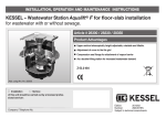
KESSEL – Pumpstation Aqualift F / Aqualift F Duo
For all wastewaters (with / without sewage)
For underground / sub-surface installation.
Product advantages
Quick and easy installation
due to leigth weight chamber
Long-life / durable due to
watertight chamber and
resitance to aggressive soils /
fluids
Additional inlets easily
connected on-site.
Vertically adjustable and
tiltable upper section
The installation and service of this unit should be carried
out by a licensed professional servicer
Company - Telephone No.
Edition 02/2004-HG
(Subject to technical amendment
ID number 010-607
This User's Manual should always remain with the Pumpstation Aqualift F.
Dear Customer,
thank you for choosing a KESSEL pumping station.
This entire system has passed a strict quality control inspection before leaving KESSEL
headquarters. Upon delivery of the lifting station please thoroughly inspect it to make sure that it
has not been damaged during shipping and that the delivery is complete.
In case damage has occurred to the lifting station or the delivery was not complete, please follow
the instructions listed in the ‚Guarantee section of this user's manual.
Before the KESSEL - Aqualift F Pumpstation is installed and placed into operation please carefully
read and follow all of the instructions contained in this Installation, Maintenance and User's
Manual.
KESSEL GmbH
2
Table of Contents
1. Safety precautions
page 4
2. General
2.1 Application / Installation
2.2 Aqualift F description
page 6
page 6
3. Technical Data
3.1 Explosion proof pumps according to ATEX
3.2 Switching levels
3.3 Electrical control unit
page 7
page 8
page 8
4. Installation
4.1 Installation
4.2 Pipe connections
4.3 Installation of the submersible pump(s)
4.4 Setting the float switches
page 11
page 15
page 16
page 16
5. Electrical Connections
5.1 General instructions
5.2 Mounting the control unit
5.3 Information concerning explosion protection
5.4 Installation – cable connection
5.5 Impeller / Motor rotation
5.6 Motor protection switch
5.7 Pump configuration control
5.8 Completion of electrical work
page 17
page 17
page 17
page 17
page 20
page 20
page 20
page 20
6. Commissioning
6.1 General instructions
6.2 Description of operation
6.3 Operational test
page 21
page 21
page 22
7. Inspection and Maintenance
7.1 Pump
7.2 Control unit
page 23
page 24
8. Problems and Solutions
8.1 General problems
8.2 Irregular level conditions
8.3 Disturbances / Internal controls
8.4 Failure warnings
8.5 Alarm warnings
8.6 What to do when
page 25
page 26
page 27
page 28
page 28
page 28
9. Control Unit
9.1 Control unit for single pump
9.2 Control unit for double pump
page 29
page 32
10. Replacement parts
page 35
11. Warranty
page 36
3
1. Safety precautions
General Safety Precautions
During installation, operation, maintenance and repair of this system it is important to follow all
appropriate DIN and VDE safety precautions as well as any application precautions in your area.
Additionally the safety precautions relating to explosion risks in wastewater pumping systems must
be followed. In danger areas, such as pump stations or septic systems, it is important that systems
with explosion proof ratings are installed. Installation and connection of these units should only be
handles by licensed, professional installers.
Qualified Personnel – Personnel responsible for the operation, maintenance, inspection and
repair of this system must be fully trained and licensed. It is the responsibility of the owner or
operator of this system to insure that the person(s) responsible for this system are fully trained and
licensed. If this is not the case the existing personnel must be immediately trained or replaced with
trained and licensed personnel. It is also the responsibility of the owner or operator to make sure
that the responsible personnel have read through and are completely familiar with this User's and
Maintenance Manual.
Caution - The Aqualift F uses electricity to operate rotating and mechanical parts.
Not following the User's Manual can result in damage to the unit as well as injury or a possible fatal
accident.
Before maintaining or servicing the Aqualift F make sure to disconnect it from ALL power sources
and secure that power cannot be re-connected during maintenance / servicing. During electrical
installation or servicing of the unit, VDE 0100 and all applicable safety regulations should be
followed.
The control unit and pressure sensor switch are electrically powered systems which should not be
opened or serviced except by licensed professional electricians. Licensed professional electrician
is defined in VDE 0105.
It is important that all electrical cables and units relating to the Aqualift F are always in good
operating condition. If damage to any of the electrical cables or systems of the Aqualift F are
noticed, the Aqualift F unit must be immediately disconnected and taken off line.
Danger of hot surfaces - During operation, the Aqualift F can become hot. Take caution before
touching or coming into contact with all hot surfaces on the Aqualift F.
Danger for hands and fingers - The Aqualift F pump is equipped with a closed impeller. Any
inspection or maintenance work must take place after the Aqualift F has been fully disconnected
from its power source. Also, during maintenance and inspection take caution
of any sharp surfaces or edges.
Slip / Crush / Fall dangers – Due to risks during entry into the pumping station chamber, it is
important that a second party remain outside of the chamber and oversee the person enterring and
performing work on the pumping system.
4
1. Safety precautions
Heavy weight - Caution
KESSEL Aqualifts with single pumps weigh approximately 45 Kg (approx 100 pounds) and double
pump systems weight approximately 84 Kg (approx. 185 Kg). The Aqualift F units should be
handled by at least two people equipped with appropriate equipments (e.g. safety shoes, back
support).
Health Safety
The Aqualift F is designed to pump wastewater containing untreated / raw sewage which can
cause health hazards. It is important that no direct or indirect contact
between the Aqualift F and skin, eyes or mouth occurs. If contact does occur it is important to
immediately wash and disinfect the contaminated area. Also, in cases when the pump itself is to be
removed from the Aqualift F, make sure that the room is properly ventilated to allow and methane
or biogases to escape or be diluted.
Noise
During operation of the Aqualift F emits approximately 65.5 dB. Based on the installation of the
Aqualift F this could present an unwanted noise. Take care in selecting the installation location of
the system. A vibration dampening support matt (available from KESSEL) may be placed
underneath the Aqualift F to reduce noise / vibration.
Pump operation
Before placing the pump(s) into operation please observe the conditions on site. The use and
operation of the pumps must be in accordance with explosion proof regulations.
Dry-running or semi-submersion of the pumps must not occur! The cutting blades, impeller and
pump housing must always be submerged underwater
The minimal submersion level must always be maintained!
The pump(s) may not be placed into operation when people are located in the wastewater storage
area of the pumping systems.
Surrounding conditions / lighting
Any additional equipment brought into the pumping station (such as external lighting or power
tools) must be equipped with the explosion proof rating.
Marking codes of explosion proof items (such as the pump and control unit) are
labelled as follows:
EX
5
2. General
2.1 Application / Installation
The Aqualift F is designed to pump wastewater (with or without sewage collected below the
outgoing sewer level) up to the sewer level so that it may flow with gravity out of the building and
into a septic system / public sewer piping. Installation examples of the Aqualift F would be single
and multi-family homes, commercial buildings, hotels, restaurants, hospitals, schools or similar
buildings. In circumstances where the interruption of wastewater is not allowed or desired, a twin
pump system (Pumpstation Aqualift F Duo) is required for installation.
The KESSEL Pumpstation Aqualift F is designed for outdoor underground installation. Pumps are
equipped with cutting blades which macerate all soft objects into smaller pumpable pieces. Due to
the cutting blades, outlet pipes of DN 40 or larger may be connected to the outlet of the
Pumpstation Aqualift F. Objects foreign to wastewater piping (such as utensiles, wood,
plastics . . .) should not come in contact with the pump's cutting assembly. The system is designed
to handle continuous inflow of wastewater up to 40 deg C (104 deg F).
The Aqualift is designed constant usage with wastewater at 35 deg C (95 deg F) and can also
handle for short durations (max 10 minutes) temperatures up to 60 deg C (140 deg F)
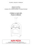
2.2 Aqualift F description
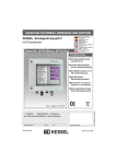
The KESSEL Pumpstation Aqualift F in single or twin pump variations is mainly comprised of the
following systems.
1. Single or double sewage pumps with cutting assembly
2. KESSEL Inspection Chamber 800 or 1000 (mm diameter)
3. Curve
4. Closure valve
5. Backflow flap
6. Pressure pipe outlet connection PN 10 from PEHD DN 50
(Outside Diameter – 63 mm or DN 80 (Outside Diameter – 90 mm)
7. Connection for ventilation pipe
8. Connection for power / control cables
9. Connection for inlet
10. Float switch
11. Electrical control unit
Illustration shows KESSEL Pumpstation Aqualift F twin pumping
unit
Options for the KESSEL Pumpstation Aqualift F include:
Single (1 pump) or Twin (2 pumps)
Pumps with 1.33 kW or 2.66 kW
In KESSEL 800 or 1000mm diameter Inspection Chamber
Installation depths from 1.5 to 5 meters.
The closure valve, backflow flap, outlet pressure pipe and float switch have already been installed
in the base of the chamber. The pump(s), additional chamber sections and the electrical control
unit are shipped separately packaged with the system. The pumps, depending on their size, are
shipped either in the chamber upper section or on a separate pallet. The pumps are to be installed
only after the complete chamber has been completely assembled and installed. In order to prevent
the build up of dangerous gases in the chamber which can cause an explosion risk, the system
must be ventilated appropriately.
6
3. Technical data
3.1 Explosion proof pumps according to ATEX
Type
Power consumption P1
Power consumption P1
Operating voltage
Frequency
Current
Cables
TPF 120 KE
1,33 kW
1,05 kW
400 V DS
50 Hz
2,5 Amps
10 m Length
7 x 1,5 mm2
Fuses
3 x 16 Amps
Protection
IP 68
Wastewater temp.
40 º C
Protection
IP 68
Max running time at 40 deg C
640 minutes (see settings
in chapter 5.7)
Pump weight
49 kg
CE 0102 II 2G EEx d IIB T4 PTB 03 ATEX 1140
TPF 154 KE
2,63 kW
2,13 kW
400 V DS
50 Hz
4,4 Amps
10 m Length
7 x 1,5 mm2
3 x 16 Amps
IP 68
40 º C
IP 68
640 minutes (see settings
in chapter 5.7)
59 kg
Classifications:
Operating modes
Pump submerged – Continuous run (S1)
Pump not submerged – Periodic run S3, 25%
(2,5 minute run, 7.5 minute pause with ambient temperature of 40 deg C (104 deg F))
Pumps with the TES . . . ex identification according to Unit Group II, Unit Category 2G (Explosion
endangered areas Zone 1 and 2) are designed for installation in atmospheres containing
dangerous gases which require the Explosion Group IIB and the Temperature Class T4. Pumps
constructed according to this designation comply with the ignition protection type 'pressure
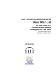
protection encapsuled`.
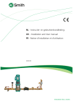
Power Curve
7
4. Technical data
3.2 Switching levels. Separate power source with blue cables and float switches
Chamber 800
Pumping Vol (l)
Height difference
(cm)
Single Pump Unit
Off – On
100
18
On – Alarm
110
20
Double Pump Unit
Off – On1
On1 – On2
On2 – Alarm
The alarm levels are at the approximate level of the inlet.
Chamber 1000
Pumping Vol (l)
Height difference
(cm)
180
200
18
20
180
100
100
18
10
10
3.3 Electrical control unit with separator power source according to ATEX.
3.3.1 General technical data
Required Fuse – max 16 Amp / phase (sourced on-site)
3.3.2 Protection
IP 65 – based on appropriate installation and securely closed see-thru cover
IP 21 – without see-thru cover and standard wall installation
3.3.3 Appropriate use
Information concerning the appropriate use of the control unit in areas at risk of explosion.
The control unit is designed to operate KESSEL single or double pump lifting stations with the use
of float switches. The control unit is not to be installed in an area designated as at risk of explosion.
Classifications
II.1)G (Eex ia) IIC/IIB (Group II, Category (1)G, designated for us in gaseous atmospheres)
The requirements of Norms EN 50014:1997 + A1 – A2, EN 50020:2002 have been fulfilled.
EG – Certification
PTB 03 ATEX 2133
Identification
II)1) G (EEx ia) IIC/II CEO123 Ta= 0 ...+ 50°C
Installation / Commissioning
The lifting stations must be installed, connected and commissioned by a licensed professional.
This professional must be trained and certified in areas including types of ignition, regulations and
work in areas at risk of explosion. Check to make sure that the pump classification (listed above)
satisfies the requirements of the installation area.
Temperatures in the immediate area of installation must be between 0 – 50 deg Celsius (32 – 122
def F).
8
3. Technical data
Electrical data / Connections
Power supply –
Jacks – N, L1, L2, L3 PE)
3 x 400 Volt (AC) / 50 Hz +- 10%
230 V (AC) / 50 Hz +- 10% to supply electronics
Um = 253 V
Based on type – max 11 VA (Electronic with protection)
up to max 16 VA (Electronic with protection)
Switch contact U=24V, I=20mA
Incoming power
(jacks TF, TF1, TF2, E7,
E8, E9, E10, based on model)
Exiting power
(Jacks N, L1)
(Jacks L1, L2, L3)
PTC – switch Um = 253 V
U = 230 V +- 10%, 2A, 50 Hz
(Warning, Relay) Um = 253 V
U = 400 V +- 10%, less then or equal to 4KW, 50 Hz
(motor protection switch).
Control unit power circuit passive (Control unit and buttons)
Single pump lifting station
Power level circuit
Jacks OFF, ON, ALARM
in ignition protection characteristics
EEx ia IIC / IIB
Highest values: Uo = 15,8 V
Io = 22 mA
Po = 86 mW
linear curve
Maximum effective interior inductiveness and capacities are minimal
Eex ia
highest certifiable exterior inductivity
highest certifiable exterior conductivity
IIC
IIB
73 mH 290 mH
478 nF 2,88 uF
If concentrated capacities / capacities exist in the power level circuit the following highest certifiable
values should be used.
Eex ia
highest certifiable exterior inductivity
highest certifiable exterior conductivity
IIC
IIB
2 mH
5 mH
420 nF 1,8 uF
Double pump lifting station
Power level circuit
Jacks OFF, ON1, ON 2
in ignition protection characteristics
EExja IIC / IIB
Highest values: Uo = 18,8 V
Io = 29 mA
Po = 115 mW
linear curve
Maximum effective interior inductiveness and capacities are minimal
Eex ia
highest certifiable exterior inductivity
highest certifiable exterior conductivity
IIC
IIB
42mH 2
168 mH
478 nF 2,88 uF
If concentrated capacities / capacities exist in the power level circuit the following highest certifiable
values should be used.
Eex ia
highest certifiable exterior inductivity
highest certifiable exterior conductivity
IIC
IIB
2 mH
5 mH
410 nF 1,8 uF
9
3. Technical data
Installation / Assembly
All appropriate local and national codes must be followed
Regulations (including safety regs) concerning the installation must be followed
Also consider the installation and assembly instruction of non- ATEX relevant units
Maintenance
Removal of the see-thru control unit cover reduces the water / moisture proof effectiveness of the
control unit. In the case that the control unit is in very moist, humid or splash endangered area,
make sure to disconnect power to the control unit before handling or maintenance work is
attempted. Removing the cover of the control unit should only be done by a licensed service
professional.
After maintenance is completed on the control unit, it is important that the control unit cover is
properly closed and secured.
No changes should be made to the control unit – such as removal of the protective see-thru
cover. In the case that the control unit does not function or is damaged, please contact the
manufacturer.
If required, date sheets, EG – certifications, User's Manuals and EG conformity certifications can
be requested form the manufacturer
3.3.4Control unit outputs
'Malfunction' relay
Change over contact; opener, middle contact, closer each with max 2A
'Alarm' relay
Change over contact; opener, middle contact, closer each with max 2A
Power
2xN
2 x L1
max. 2A each
max. 2A each
Motor (single pump unit)
Motor PE
Power connections (grey double inlet jack)
Motor U
T1 Protection
Motor V
T2 Protection
Motor W
T3 Protection
Motor ½ (double pump unit)
Motor ½
PE
Power connection
quadruple power jacks
Motor ½
U
T1 protection ½
Motor ½
V
T2 protection ½
Motor ½
W
T3 protection ½
10
4. Installation
When the shipment arrives, please inspect it immediately for damages which may have
been caused during transport / shipping!
The delivered shipment should include the following:
KESSEL Inspection Chamber delivered in sections (for assembly on-site)
Sewage pump(s)
Electrical Control Unit
Caution The base of the inspection chamber as well as the pumps and chamber cover each way
over 30 kg! Be sure that appropriate personel and equipment (e.g. safety shoes, back support,
etc.). The pumps should be placed into the chamber after the chamber is installed and lowered into
the chamber only with an appropriate winch / lowering assembly.
Important After the receiving the Aqualift F but before installation, it is important that the control
unit is stored in a dry, frost free area until time of connection. The cable ends of the float switches
must not come in contact with water while they are being stored.
Caution - Danger of slipping While enterring or working in or around a chamber the danger of
slipping is always present. Due to this it is mandatory that a second worker always remains outside
of the chamber to aide / observe the other.
Caution – Danger of tipping Before the trench / hole is backfilled with soil, the possibility that the
chamber tips or falls is always present. Due to this, entry into the chamber should only take place
after the hole, in which the chamber is installed, is backfilled.
4.1 Installation
The base / bottom of the hole in which the Aqualift F is to be installed should be prepared with 30
cm even layer of compacted gravel. On top of this layer of gravel should be a 10 cm thick evenly
compacted layer of fine gravel. Now place the bottom section of the pumping chamber into the
excavation making sure that inlets / outlet, ventilation and pipe cable outlets are in the correct
location.
The excavation is then to be backfilled in 30 cm layers with gravel (no sharp stones allowed)(gravel
to be group G1 according to ATV-A127). Each of these 30 cm layers is to be compacted. Make
sure to connect any necessary inlets / outlet or other pipes before these areas are backfilled. In the
case that the chamber is to be installed in an area that is subject to rising groundwater, the
chamber must be protected against floatation. To protect the chamber against groundwater the
entire lower portion of the chamber (including the bottom of the chamber)(up to a height that is
higher than the highest possible groundwater level) must be covered / surrounded by concrete. To
help anchor the chamber, 10 mm steel anchor rods (hooks) (as seen in the illustration) must be
installed.
11
4. Installation
Installing the chamber seals / gaskets
Each of chamber sections is connect using a gasket (the size of this gasket will vary depending on
if an 800 or 1000 chamber is being installed and on the specific section being installed. The
recessed area for the gasket (located on the top of each section as seen in the illustration) should
be clean and free from all debris / sand. Firmly place the gasket into the recessed area of the
chamber. After the entire gasket has been installed – grease the gasket with a standard gasket
lubricant. Insert an access step if desired (KESSEL 1000 chambers come standard with access
steps – steps for the 800 chambers are available upon request).
Access steps ( only standard with KESSEL 1000 chamber )
12
4. Installation
Installing chamber sections
Now place the next chamber section on top of the other making sure that the location for access
steps are in line with the lower portion. The sections are secured with another with the supplied
connection clips which should be installed as illustrated.
Installation of the vertically adjustable upper section:
Installing the vertically adjustable upper sections.
Firmly insert custom gasket into cone section using hammer if required
Grease custom gasket, insert upper section and secure with clamping ring
Final elevation / slope adjustments can be made with the 3 adjustment screws
13
4. Installation
After the upper section has been set to its final elevation and slope, it is important to note the
following:
Cobble stone installation – in the case that the upper section and cover will be installed in a stone
/ cobble stone surface, it is important that the top of the upper section is placed approx 2 cm
higher than that of the cobble stones. When the cobble stones are compacted the upper section
and cover should also be compacted (be sure to tighten cover screws before compacting) until it
is level with the surrounding stones.
Installation in automobile traffic areas – in the case that the upper section and cover will be
installed in a surface which is to handle Class D (40.0 metric ton load classes), a 18cm thick,
2m x 2m concrete support plate must be poured around the upper section. The concrete
support plate should be steel re-enforced and comply with any local regulations. A sample
drawing of this load support plate is available from KESSEL.
In some instances it may be required that the lower section of the upper section be sawed off in
order to obtain the correct installation depth. This cut should be made as evenly as possible and
any remaining loose edges should be filed away. The included manhole cover removal key as
well as the User's Manual for the pumping system should be stored in a protected dry area in
the near vacinity of the control unit.
KESSEL – Pumpstation Aqualift F in 1000 Inspection Chamber
Installation depths from 1.63 to 5.13 meters
KESSEL – Pumpstation Aqualift F in 800 Inspection Chamber
Installation depths from 1.46 to 1.96 meters
14
4. Installation
4.2 Pipe connections
All pipes are to be laid with negative slope into the Pumpstation Aqualift F Chamber – meaning that
fluids will flow with gravity out of the pipe and into the Pumpstation. All pipe connections must be
flexible connections and be installed with sound dampening accessories. The DN 100 pipe
connections for the inlets, ventilation and cable supply can be made with standard DN 100 KG
piping.
According to DIN 1986 the inlet pipe(s) must have a minimum 2 % slope into the Pumpstations.
Bends and fittings should be used as little as possible. The connection to the DN 100 inlet to the
Pumpstation can be made with a female-female fitting.
All electrical cable going to or from the Pumpstation should be installed in one cable supply pipe.
This cable supply pipe may be used for no other purpose other then running cables. Curves /
Bends in the cable supply pipe should be handled with 30 or 45 degree fittings (no 67 or 90 degree
bends should be used which could complicate running cables at a later date). After all electrical
installations have been completed it is important that the cable supply pipe is completely seals
against air or waste penetration. This can be accomplished with specials cable sealing inserts or
with special expansion foams.
The ventilation pipe serves to compensate vacuums or pressure build-ups which can occur inside
the Pumpstation as it is filled with wastewater or as wastewater is pumped out of the system. Since
these systems are normally installed close to the building which they serve, it is recommended that
the Pumpstation's ventilation pipe be run to the roof of the building – this will prevent odor
nuisances in the future. If the opportunity exists, the Pumpstation's ventilation pipe can be
connected to the building's existing ventilation pipe.
The Pumpstation is shipped with installed inlet and ventilation port inlets including gaskets. These
should be used for connection of the inlet and ventilation pipes. These gaskets should be
lubricated before KG inlet and ventilation piping is attached.
The outlet pressure pipe (connected to a private or public sewer system) should be connected to
the supplied outlet using PN 10 PEHD DN 50 (OD 63mm) or DN 80 (OD 90mm) piping. This
connection can be made by welding the plastic together or by using appropriate heavy duty
couplings. It is important that this outlet pipe be plumbed over the local backwater height and then
down into the private or public sewer. A direct solid connection from the pressure pipe outlet to the
building should not exist – this will prevent noise / vibrations being transferred to the building.
15
4. Installation
4.3 Installation of the submersible pump(s).
Caution – the Aqualift F submersible pumps weigh between 49 and 59 kg. These pumps should
only be lifted and installed in the Pumpstation using appropriate lifting and pully devices. If an
installation or maintenance worker needs to enter the Pumpstation there should always be at least
one observer who remains outside of the chamber.
Before installing the submersible pumps(s) check the inside of the Pumpstation to make sure it is
free of any debris or waste. Once the chamber is cleaned, the pump(s) should be lowered with the
aide of a mechanical lowering device (pulley) onto the steel guide bars and to the bottom of the
chamber making sure that the pump(s) make firm contact with the bottom of the guides. Remove
the lowering chain from the pulley and attach it to the hook located in the upper section of the
chamber.
Important – After installing the pump(s) make sure that the closure valves are in the open position
(lever should be in the vertical position).
4.4 Setting the float switches
Single pump unit
This Pumping station is equipped with one submersible sewage pump. The system is controlled by
3 float switches. The function of these 3 float switches are Pump OFF, Pump ON and ALARM. The
float switches have been installed and set at the factory. The float switches have been set so that
the ALARM float switch will activate when the wastewater level inside the chamber reaches the
bottom of the inlet pipe level of the pumpstation.
If other pumping levels are desired, the float switches must be changed on-site. Important is that
the ALARM float switch activation point is not set above the inlet pipe elevation and that the Pump
OFF float switch is not set too low – this will prevent the pump from intaking air. Ideally, the
submersible pump should be totally underwater before pumping begins.
Double pump unit
This Pumping station is equipped with two identical submersible sewage pumps. The system is
controlled by 4 float switches. The function of these 3 float switches are Pump OFF,
Pump 1 ON, Pump 2 ON and ALARM. The float switches have been installed and set at the
factory. The float switches have been set so that the ALARM float switch will activate when the
wastewater level inside the chamber reaches the bottom of the inlet pipe level of the pumpstation.
If other pumping levels are desired, the float switches must be changed on-site. Important is that
the ALARM float switch activation point is not set above the inlet pipe elevation and that the Pump
OFF float switch is not set too low – this will prevent the pump(s) from intaking air. Ideally, the
submersible pump should be totally underwater before pumping begins.
16
5. Electrical connections
NOTICE – Only certified licensed professionals should conduct the following electrical
connections.
5.1 General instructions
The control unit for the Pumpstation Aqualift F must be connected to a separator main switch so
that if required the entire system can be switched off line.
All cables enterring the control unit must be secured to the control unit using the supplied plastic
strain relief nuts. Cable inlet openings into the control unit which are not used must be properly
closed.
Important – All electrical cables must be properly secured (with tie-wraps for example) so that in
the case that the cable releases from the control unit that the bare ends of the cables do not come
in contact with any other cables (for example in the case that cable L1 comes out of the input jacks
it will physically be impossible for this cable to contact the PELV).
All local and national safety regulation should be followed. If these codes are not strictly followed, a
danger to people and maintenance worker could exist. After any work on the control unit has been
completed, the see-thru cover must be properly secured (touch and spray water proof).
The cable for the control unit (especially the float switch cables) must be kept separate from the
power and pump cables to prevent interference.
5.2 Mounting of control unit
The control unit for this pumping station is to be installed in a frost-free, dry and well-ventilated
area. The control unit may not be installed in an explosion endangered area. The conrol unit is to
be installed on a solid wall. Screw holes can be drilled using the available template. To access the
control unit mounting screws first remove the see-thru cover. The cables for the pump(s) and the
float switches should be run through an empty pipe to the control unit. To connect these cables
please follow the instructions in Chapter 5.4 ' Installation – Cable connection'.
5.3 Information concerning explosion protection
When connected cables inside the control unit make sure that the cables are connected to their
appropriate jacks. Float switch cables must be connected to float switch jacks and power and
pump cables must be connected to their appropriate jacks. Improper connection of cables could
damage the system as well as nullify the explosion proof rating of the system.
5.4 Installation – Cable connection
The cables for the pump(s) and the float switches are 10 meters in length. The cables between
pumping station and building must be run in a empty pipe (as discussed in Chapter 4.2). In the
case that the 10 meter cable lengths is not sufficient, the cables may be extending following VDE
codes.
Important – All electrical cables must be installed so that they do not come in contact with the
submersible pump(s) and are clear of the access steps. The cables must also be installed to allow
the removal of one or both of the submersible pumps for inspection and / or maintenance
purposes.
17
5. Electrical connections
Cable connections for pumpstation Aqualift F single pump unit
Power cable connections.
1. Power cables L1, L2, L3, N and PE should be connected to their appropriate jacks (grey
color jacks located on above level). Please see the color coded installation help located
near the connection area.
2. It is mandatory that cables N and PE are connected and connected properly.
3. The power supply cable to the control unit must be equipped with a main On / Off switch.
4. Each phase of the main power cable must be equipped with a fuse with a max rating of 16
Amps.
5. Improper electrical installation / connection of the control unit and / or pumps can damage or
destroy the control system.
Motor / pump cables.
The motor / pump cables U/V/W should be connected to the ABB-Schütze B6-30-10 jacks T1 / T2
/ T3 which are to the left of the motor protection switches. The direction of rotation of the motors
is to be noted.
The PE cable is to be connected to the lower level of grey jacks according to the coded
installation help located near the connection area.
The motor cables must be connected so that removal of the pump(s) for repair or maintenance is
possible.
Motor temperature sensors.
Entry TF: Cable 4 from Pump 1 should be connected on the right in entry TF. Cable 5 should be
connected to the left of entry TF.
Entry TF: Cable 4 from Pump 1 should be connected on the right in entry TF. Cable 5 should be
connected to the left of entry TF.
Entry E7: Cable 6 from should be connected on the left in entry E7. (remove the bridge if
necessary).
Float switch connections - 'Off', 'On' and 'Alarm'
The cable ends of the float switches are to be connected to their corresponding marked jacks.
No other cables or power sources should be connected in the jacks for the float switches.
The connection jacks are marked with switching symbols.
Outputs L1 / N (230 Volt / 50 Hz)
The L1 and N outputs (2 each) are designed for an external (extra) warning for the 'Malfuntion' and
'Alarm' functions. These outputs may not be used for any other purposes.
Rechargeable battery.
6. A NiCd-9V-Block rechargeable battery (Type IEC 6F22) is to be used inside the control unit. The
purpose of this battery is to power the alarm and notification devices on the control unit during
power outages / failures.
7. Only remove or replace the battery in the control unit when the power to the entire control unit
has been turned off / disconnected.
8. In the case that a 'dead' or power-less rechargeable battery is placed in the control unit, the unit
will require approximately 36 hours to completely re-charge the battery. After this 36 hours the
battery and the control unit will be fully operational.
18
5. Electrical connections
Cable connections for pumpstation Aqualift F double pump unit
Power cable connections.
6.Power cables L1, L2, L3, N and PE should be connected to their appropriate jacks (the
second row of jacks from the bottom). Please see the color coded installation help located
near the connection area.
7.It is mandatory that cables N and PE are connected and connected properly.
8.The power supply cable to the control unit must be equipped with a main On / Off switch.
9.Each phase of the main power cable must be equipped with a fuse with a max rating of 25
Amps.
10.Improper electrical installation / connection of the control unit and / or pumps can damage or
destroy the control system.
Motor / Pump cables.
The motor / pump cables U/V/W x 2 should be connected to the ABB-Schütze B6-30-10 screw
jacks T1 / T2 / T3 (Pump 1 left, Pump 2 right). The direction of rotation of the motors is to be
noted.
The PE cable is to be connected to the upper of jacks according to the coded installation help
located near the connection area.
The motor cables must be connected so that removal of the pump(s) for repair or maintenance is
possible.
Motor temperature sensors.
Entry TF1: Cable 4 from Pump 1 should be connected on the right in entry TF1. Cable 5 should
be connected to the left of entry TF1.
Entry TF2: Cable 4 from Pump 2 should be connected on the right in entry TF2. Cable 5 should
be connected to the left of entry TF2.
Entry E7: Cable 6 from Pump 1 should be connected on the left in entry E7. (remove the bridge
if necessary).
Entry E8: Cable 6 from Pump 2 should be connected on the left in entry E8. (remove the bridge
if necessary).
Float switch connections – 'Off', 'On 1', 'On 2' and'Alarm'
The cable ends of the float switches are to be connected to their corresponding marked jacks.
No other cables or power sources should be connected in the jacks for the float switches.
The connection jacks are marked with switching symbols.
Outputs L1 / N (230 Volt / 50 Hz)
The L1 and N outputs (2 each) are designed for an external (extra) warning for the 'Malfunction'
and 'Alarm' functions. These outputs may not be used for any other purposes.
Rechargeable battery.
9. A NiCd-9V-Block rechargeable battery (Type IEC 6F22) is to be used inside the control unit. The
purpose of this battery is to power the alarm and notification devices on the control unit during
power outages / failures.
10. Only remove or replace the battery in the control unit when the power to the entire control unit
has been turned off / disconnected.
11. In the case that a 'dead' or power-less rechargeable battery is placed in the control unit, the
unit will require approximately 36 hours to completely re-charge the battery. After this 36 hours
the battery and the control unit will be fully operational.
19
5. Electrical connections
5.5 Impeller / Motor rotation
Before placing the Aqualift F into operation, check to make sure that the rotation of the motor /
impeller is correct. An arrow on the pump housing shows the correct direction of rotation. If the
impeller turns in the wrong direction either switch L1 with L2 or switch L2 with L3.
5.6 Motor protection switch
The motor protection switch must be set to handle the appropriate power rating listed in Chapter
3.1 of this User's Manual.
5.7 Pump configuration control
The control of the pump configuration is set at the factory using switches S601 . . . S604 located
between the jacks for the float switches and the motor thermal protection entry ports. The
configurations should be checked to make sure they are properly set.
The configuration can be set by adjusting the S604 switch ( 4-way DIP switch each with ON/OFF
setting). Different settings are not permitted.
S604/1
S604/2
S604/3
S604/4
level controlled
OFF OFF
with OFF level switch
OFF OFF
rotation monitor on
ON ON
anti-blocking function on ONON
S604/1
S604/2
S604/3
S604/4
level controlled
OFF OFF
without OFF level switch ONON
rotation monitor on
ON ON
anti-blocking function
ON ON
The pump start delay time can be custom set by adjusting the S601 switch. This delay can be set
between 0 and 3 seconds in 0.2 second increments. (tolerance +- 0.1 seconds)
The maximum running time can be custom set by adjusting the S602 switch. This can be set
between 40 and 640 minutes in 40 minute increments (tolerance +- 4 minutes)
The pump stop delay time can be custom set by adjusting the S603 switch. This can be set
between 0.5 and 8 seconds in 0.5 second increments (tolerance +- 0.1 seconds)
Before making any of the above adjustments make sure to disconnect the Aqualift F from its power
source. Any setting changes should be handled by a licensed professional and should be
documented in this User's Manual.
Make sure that the pump control switches (Hand – 0 – Auto) are switched to the 'Auto' setting.
5.8 Completion of electrical work
After all electrical work has been completed on the Aqualift F or the control unit make sure replace
the cover and the transparent cover of the control unit.
20
6. Commissioning
6.1 General instructions
Please follow DIN 1986 Part 31 when commissioning pumps / lifting stations
Caution - Before commissioning the Aqualift F make sure that all inlet pipes as well Aqualift F
storage chamber and the pump is free from metal, sand or any other potentially damaging debris.
Only place the Aqualift F into operation after it has been thoroughly checked to assure that
installation and pipe and electrical connection have been properly made. Make sure that all closure
valves are fully open before starting.
Important - the commissioning of the Aqualift F must be handled by a licensed professional.
Make sure to follow all safety instructions in Part 1 of this User's manual and do not place the
Aqualift F in operation if the pump, control unit or cables show any signs of damage.
Important - All screws / bolts should be tighten to a maximum of 3 Nm
6.2 Description of operation
6.2.1 'Auto' mode
Single pump unit
The single pump Pumpstation Aqualift F is in standard operating mode when the control unit switch
is set to 'Auto' and no failures or warnings are displayed. As the wastewater level inside the
Aqualift F storage chamber rises the level will reach the 'Pump Off' level and then reach the 'Pump
On' level. After the wastewater level has reached the 'Pump On' level and after the pump start
delay time has elapsed the pump will begin operation. As the wastewater level decreases the
'Pump Off' float switch level will be reached and the motor will continue pumping until the pump
stop delay time has elapsed. In the case that the pump runs for longer than the set maximum
pump run time, the pump will turn off and at this time the 'Laufzeit' LED will turn on to let the
operator know that the motor has run to its maximum run time. The warning will remain until the
'Alarm Reset' button is pressed. Pressing the 'Alarm Reset' button will then allow the pump to
restart.
Double pump unit
The double pump Pumpstation Aqualift F is in standard operating mode when both control unit
pump switches are set to 'Auto' and no failures or warnings are displayed.
Alternating operation
The pumps in the double pump Pumpstation Aqualift F are designed to operate alternatively. After
the wastewater inside the chamber reached the pumping height, one of the pumps will turn on and
pump out the entire contents of the chamber. The next time the wastewater reaches the pumping
height – the other pump will turn on and pump out the entire contents of the chamber. If one of the
pump malfunctions or is improperly connected the other pump will handle all pumping of the
wastewater.
21
6. Commissioning
Parallel operation
In the case that one pump cannot handle the incoming amounts of wastewater, the second pump
will also activate when the wastewater level inside the chamber has reached the 'Pump 2 On' level.
Both pump will then continue to operate simultaneously until the 'Pump Off' level has been
reached.
In the case that one or both of the pumps runs for longer than the set maximum pump run time, the
pump(s) will turn off and at this time the 'Laufzeit' LED will turn on to let the operator know that the
motor has run to its maximum run time. The warning will remain until the 'Alarm Reset' button is
pressed. Pressing the 'Alarm Reset' button will then allow the pump to restart.
6.2.2 'O' Mode
When the switch for a pump is set to the '0' setting, this pump will not operate although the warning
and failure displays on the control unit will continue to function. If both switches are set to 'O'
neither of the pumps will operate.
6.2. 'Hand' Mode
When the control unit is set to the 'Hand' mode the pump will begin (or continue) to run (regardless
of the wastewater level inside the Aqualift F) until switched back to the 'O' or 'Auto' setting.
Attention - A pump running without water circulating through it causes increase temperatures and
a drastic increase on the wear and tear of the motor. Excessive dry running of the pump(s) (above
5 minutes) can lead to irreparable damage to the pump(s). This damage is easily detectable and is
not covered under the Pumpstation Aqualift F warranty.
6.3 Operational test
The functions of the Aqualift F, dependant on wastewater levels inside the unit, should be tested
after installation by filling up the Aqualift F with wastewater to specific levels. Filling of the unit
should take place by draining fixtures connected to the unit.
22
7. Inspection and maintenance
Inspection
The Pumpstation Aqualift F should be inspected monthly by the owner to make sure it is
functioning properly and is water tight.
Caution !!!
Before conducting any maintenance on this unit make sure to unplug the entire unit from its
power source.
All of the inspection and maintenance instruction listed below should be handled by an
authorized service professional.
Repairs should only be handled by the manufacturer
Maintenance
DIN 1986 - 31 should be followed when maintaining this unit. Maintenance should be handled by
an authorized professional and should include the following:
Visual inspection of the pump and the pump pump housing / chamber
Check for obvious wear and tear and build up of deposits on the pump
Connection cables should be inspected for damage
Closure valve to be tested to assure function
Inspection chamber checked for leaks and for any build up of deposits
Scheduled maintenance should be scheduled as follows:
Units in commercial application should be maintained every 3 months.
Units in residential (multi-family homes) should be maintained every 6 months.
Units in single family homes should be maintained every year.
7.1 Pump
Caution !!!
Take caution when lifting or moving the Aqualift. Additional help or a lifting device may be
needed to safely remove the pumps from the chamber.
For general maintenance it is recommended (after the power source to the pump is disconnected)
that the pump is removed from the chamber, placed on a firm surface and cleaned (for example
using a garden hose). Only the inspection and maintenance work described in this section should
be undertaken - no other work is recommended.
7.1.1 Seals (water tightness)
The seals on the rotor shaft should be inspected after the first 500 hours of pump use. After this
initial inspection the seals should be checked every six months or after 1000 hours of operation,
whichever comes first. The seal on the rotor between the motor and the pump is created by two
floating ring seals which have a oil holding chamber between them. The condition of the floating
seal on the bottom of the pump (the pumping medium side) can be checked by examining the oil.
In order to complete this check, the two oil outlet plug screws have to be removed (see illustration).
After removing the two oil outlet plug screws the oil can be poured into a clear glass container. If
the oil is clean and clear then the lower floating ring seal is still in good condition. If the oil is milky
and cloudy or this chamber contains dirty water, then this lower floating ring seal needs to be
replaced. The replacement of this seal should only be handled by a qualified professional. While
replacing the lower seal, the professional should also check the condition of the above seal. If the
oil needs to be changed, replace with DEA SERA 32, MINOLR 32 or SHELL TELLUS 29 oil. The
quantity of replacement oil need is 1.6 liters for the 120KE pumps and 1.8 liters for the 154KE
pumps.
7.1.2 Macerating blades (cutting blades)
The cutting blades of the pump should be checked during the 6 month inspection or if operation of
the pump becomes louder. The distance between the rotating surface and the cutting blades
should be 0.1 to 0.2 mm. Setting this distance can be accomplished by loosening the 4 holding
screws on the cutting blades and then adjusting the distance between the rotating surface and the
cutting blades by using the cutting blade adjustment screws (quantity - 4). After the distance has
been set, holding screws should be firmly tightened. These holding screws should be secured with
LOCTITE 242 or WEICON AN 302-42.
23
7. Inspection and maintenance
7.1.3 Bearings
The bearings are permanently lubricated and are maintenance free. However, if operation of the
motor becomes louder and louder, the bearings should be inspected. This can be confirmed if the
rotor is difficult to turn by hand or when turning the rotor / impeller by hand it is noticed that the
rotation axis is not exact (rotor is not firmly in place).
7.1.4 Impeller
In cases where the performance of the pump decreases, the condition of the impeller should be
checked for wear and tear. Before placing the Aqualift F Pumpstation in service or if the Aqualift
has not been in service for an extended period of time, the impeller should be turned by hand to
make sure that it rotates smoothly.
Text from Illustrations
Rillenkugellager –
Deep groove ball bearing
Schrägkugellager –
Bearings (slanted)
Wellen / Gleitringdichtung
- Rotor seals upper (motor
side)
Wellen / Gleitringdichtung
- Rotor seals lower (medium
side)
Laufrad Impeller
Justierschraube –
cutting blade adjustment
screws (quantity - 4)
Ölablaßschraube –
oil outlet plug screws
(quantity-2)
Befestigungsschrauben –
Cutting blade holding
screws (quantity-4)
Schneideinrichtung –
Exterior positioned cutting
surface and interior
positioned rotating cutting
blades
7.2 Control unit
11. The batteries inside the control unit should be inspected at least once per year and
replaced if necessary. Replacement batteries should be identical to the originals. Dispose
of old batteries properly.
12. The motor protection switch is a wear and tear part and should be checked every year and
replaced if necessary. Please replace with the identical switch and dispose of the old switch
properly.
13. Please make sure the see-thru cover of the control unit is properly closed and tightened.
14. Repairs of the control unit should be undertaken by the manufacturer.
24
8. Problems and solutions
The following problems and solutions should only be checked and handled by a licensed
professional serviceman / woman.
8.1 General problems
Problem
1. Pump does not start
Reason
Control unit switch not on 'Auto'
mode
Motor protecting switch has
activated and is blocking motor
Motor turns with difficulty
1 or 2 phases not receiving
power
2. Pump(s) run but cannot Too much wastewater enterring
handle volume of incoming system
wastewater
Pump performance not
satisfactory
Solution
Set switch to 'Auto' setting
Inspect pump / impeller and
remove any obstruction.
Customer service repair required
Check fuses and cable
connections
Check incoming wastewater
source – shut down unnecessary
sources or redirect specific
sources away from system
- remove obstruction from impeller
- remove obstruction from outlet
pipe
- make sure backflow flap is
completely open
-Pump(s), impeller(s) worn out and
need replacement
3. Pump(s) run rough or
loud and 'Phase / Drehfeld'
LED does not light
Motor / Impellers rotating in
wrong direction
- Improper specification of system,
pumps too weak to handle
volumes
Check rotation, switch 2 phases
(cables) of main power cable
With double pump system – bothSwitch two phases from the main
motors / Impellers rotating in
power cable on control unit.
wrong direction
Low pump performance due to Pump(s) and motor(s) to be
damage
checked and repaired by customer
service if necessary
Check rotation, switch 2 phases
Pump(s) run rough or loud Motor / Impellers rotating in
(cables) of main motor power
and 'Phase / Drehfeld' LED wrong direction
cable
does not light
With double pump system – bothSwitch two phases from the main
motors / Impellers rotating in
motor cable on control unit.
wrong direction
System not turn on
Place control unit switch on 'Auto'
4. Wastewater not being
mode
pumped out of system –
backwater from connected
fixtures
Power cables to control unit not Check fuses. Check power supply
receiving power
Inlet pipe(s) to Aqualift F blockedCheck and clean inlet pipes
Inlet closure valves closed or not Make sure any inlet valves or
completely open
locks are completely open.
25
8. Problems and solutions
5. System suddenly
operation very loud
6. Bad odor
Sharp, biting odor
7. Pump(s) running too
much, starting for not
reason
Phases have been switched
accidentally
Pump(s) damage or cutting
assembly damage
Foreign object in pump
Check rotation and switch rotation
if necessary
Check pump(s) and replace any
damage parts
Check pump(s) / impeller(s) and
remove and obstruction
Pumping chamber has a leak
Check chamber, inlet, outlet, cable
and is no longer water / air tight pipe for leaks
Motor(s) operating too hot
Check for free rotation of motor(s)
/ impeller(s)
Pump(s) starting and stopping to Check with customer service
frequently
Incoming volume of wastewater Reduce incoming wastewater
exceeding systems capacity
volume
Aqualift F's backflow preventer
malfunctioning – wastewater
flowing back into chamber
Connection between base of
pump and outlet pipe not
watertight
8. Pump(s) run continuously Foam build up inside system
Grease / fats coating tank and
pump(s)
Check and clean backflow
preventer – replace if necessary
Remove pump, check sealing
gasket – properly replace pump
and check for proper connection.
Replace gasket if necessary
Reduce use of dishwashing /
clotheswashing detergents
Completely clean system – check
source of incoming greases / fats
and reduce or remove source
Float switch set incorrectly or
Check float switch connections,
broken. Float switches jammed
clean and remove and
by obstruction or dirty / grease
obstructions.
8.2 Irregular level conditions
Problems or failures with the level switches can often be detected by the control unit and be
displayed while in the Auto mode. If the control unit detects an impossible level switch situation, the
'Laufzeit / Niveau' LED will begin to blink. This can be confirmed and cancelled by pressing the
'Alarm Reset' button if the problem has been fixed or the wastewater level has changed and this
'impossible' level is no longer present. Problems with the 'Alarm' closure switch and the opening of
the 'On' level switch cannot be detected.
26
8. Problems and solutions
Single pump Aqualift F
'Pump Off' float switch which does not shut off.
In the case that the 'Pump Off' foat switch does not shut off, the alarm warning will be activated
when the wastewater level rises above the 'Pump On' level. The pump will turn off when the
wastewater level falls below the 'Pump On' level.
'Pump On' float switch which does not shut off.
The alarm will activate and the pump will start when the wastewater rises above the 'Alarm On'
level. Pump will turn off when the level falls below the 'Pump On' level.
'Pump On' float switch which is stuck in the 'On' position.
A warning will be displayed after the wastewater falls below the 'Pump Off' level. The pump will
now turn on only when the wastewater level has risen above the 'Alarm' level and will turn off after
the level falls below the 'Pump Off' level. The warning can be cancelled by pressing the 'Alarm
Reset' button after the float switch has been repaired.
'Alarm' float switch is stuck in the 'On' position.
A warning will be displayed after the wastewater level has fallen below the 'Pump On' level – the
warning will be a continuous ( non-stop) warning. During this situation, the pump will start when the
wastewater level has risen above the 'Pump On' level and will stop after the level has fallen below
the 'Pump Off' level.
Double pump Aqualift F
''Pump Off' float switch which does not shut off.
In the case that the 'Pump Off' foat switch does not shut off, the alarm warning will be activated
when the wastewater level rises above the 'Pump 1 On' level. Both pumps will turn on when the
wastewater level rises above the 'Pump 2 On' level and will turn off when the level falls below the
'Pump 1 On' level.
'Pump On' float switch which does not shut off.
The alarm will activate and both pumps will start when the wastewater rises above the 'Alarm On'
level. Both pumps will turn off when the level falls below the 'Pumps Off' level.
'Pump 2 On' float switch which does not shut off.
An alarm will activate after the wastewater level has risen above the 'Alarm' level. At the same time
the second pump will start. Both pumps will continue to run until the 'Pumps off' level has been
reached.
Constantly closed 'Pump 1 On' level switch
An alarm will activate after the wastewater level has fallen below the 'Pumps Off' level. Both pumps
will start again when the level reached the 'Pump 2 On' level and will both turn off when the level
falls below the 'Pumps Off' level
Constantly closed 'Pump 2 On' level switch
An alarm will activate after the wastewater level has fallen below the 'Pump 1 On' level. One pump
will activate after the level rises above the 'Pump 1 On' level and the second pump will activate
after the 'Alarm' level has been reached. Both pumps will turn off after the level falls below the
'Pump Off' level.
Constantly closed 'Alarm' level switch
The 'Level' alarm will activate when the 'Alarm' level is activated AND the 'Pump 2 On' level has
been reached. One pump will activate when the wastewater level reaches the 'Pump 1 On' level
and the second pump will activate when the 'Pump 2 On' level has been reached. Both pumps will
turn off after the 'Pumps Off' level has been reached.
8.3 Disturbances / Internal controls
The control unit continuously monitors the signals from the motor protection switches and the
motor temperature sensors. In the case of a disturbance the pump will either be shut off or
prevented from starting. This will result in a corresponding alarm and the lighting of an LED.
8.3.1In the case that L2 and / or L3 fail, the 'Phase/Drehfeld' LED will continuously light and the
'Störung' relay will activate. Since the control of L1 is still active, the failure of L1 will not be
displayed. In the case that the motor rotation is wrong (left) the 'Phase / Drehfeld' LED will blink.
27
8. Problems and solutions
In the operational mode 'Hand' it is possible to run the pump with the incorrect rotation – in all other
operational modes the control unit will block the functioning of the motor in the case that the
rotation is incorrect.
8.3.2 In the case that a motor protection switch is activated either manually, by a short circuit or by
an overload, the 'Motorschutzschalter' LED will activate ('Pumpe . . . MSS/Temp' LED). With
double pump systems the LED 'Pumpe . . . MSS/Temp' has priority over a motor / pump
temperature warning.
8.3.3 Each motor of the Pumpstation Aqualift F contains two temperature sensors which send data
to the control unit.
Temperature level A (not recorded) – The 'Motortemperatur' LED blinks (with doule pump units the
'Pumpe . . . MSS/Temp' LED blinks) – when temperature level A has been reached
Temperature level B (recorded) – The 'Motortemperatur' LED turns on (continuously on)
(with double pump units the 'Pumpe . . . MSS/Temp' LED blinks) – when temperature level B has
been reached.
In the case that temperature level A has been reached the 'Motortemperatur' LED will blink (also
'Pumpe .. . MSS/Temp' LED with double pump units will blink) and the 'Störung' relay will activate.
Also the control unit will shut down the pumps. As soon as the pumps cool down below the
specified level, the pump will return to normal operation. In the case that temperature level B has
been reached the 'Motortemperatur' LED will turn on and remain on ('Pumpe .. . MSS/Temp' LED
will blink with double pump units) and the 'Störung' relay will activate. Also the control unit will shut
down the pumps and this failure will be recorded by the control unit and must be erased by
pressing the 'Alarm Reset' button. This is only possible when the temperature sensors sense a
normal operating temperature. In the case of a power outage, the 'Temperature B' information will
not be recorded. In the case that the 'Temperature B' level has been reached and the wastewater
level has reached the 'Alarm' level – the following can be performed:
By pressing the 'Alarm Reset' button once, the internal signal will be cancelled.
By pressing the 'Alarm Reset' button twice, the 'Temperature B' will be erased.
8.4 Failure warnings
Failure warnings will occur by:
the activation of the failure relay and the connected warning device
display of the type of failure by LEDs on the control unit resulting from
Single pump units
Double pump units
Phase / rotation problems
Phase / rotation problems
Motor protection switch
Pump 2 MSS/Temp
Motor temperature
Pump 1 MSS/Temp
Running times / level
Running times / level
8.5 'Alarm' warnings
Alarm warnings occur from:
the activation of the Alarm relay and the connected warning device
the internal signal
Two situations can result in an alarm warning:
1.The wastewater level inside the chamber rises above the level of the 'Alarm' float switch. The
internal audible alarm can be turned off by pressing the 'Alarm Reset' button. As soon as the
wastewater has fallen below the 'Alarm' float level both alarms (signal and relay) will be cancelled.
2.If a loaded battery is placed in the control unit, an audible alarm will be activated in the case of a
power failure. This audible alarm will continue for up to 3 hours depending on the power in the
battery. This alarm can be cancelled by pressing the 'Alarm Reset' button.
8.6 What to do when . . . .
The motor protection switch is activated - Open the transparent cover of the control unit and press
the 'START' button. If the motor protection switch reactivated immediately after being pressed
please contact a licensed electrician.
The Aqualift F no longer reacts to incoming signals (for example from the float switches) - unplug
the control unit of the Aqualift F for at least 10 seconds and then plug back in. In the case that
the Aqualift still no longer response to incoming signal please contact a licensed professional.
28
9. Control unit
9.1 Control unit for single pump pumpstation Aqualift F
9.1.1 Description of displays and operational button on control unit
Normal operation
Information for User
Warnings
Information for Tradesman
Buttons
Hand - 0 - Auto (Pump 1)
Alarm reset
Betrieb
green
power supply functioning
'Alarm' level
'On 2' level
'On 1' level
'Off' level
Pump1
yellow
yellow
yellow
yellow
green
'Alarm' level reached
pump 2 on level reached
pump 1 on level reached
Pump off level reached
pump outlet 1 activated
Phase
red
constant - phase not active
blinking - rotating field
problem
Motor protection
switch
red
Motor protection switch has
been acitivated
Motor temperature red
Constant –
'Temperature B' (E7)
Blinking – '
Temperature A' (TF)
Running time/level red
constant - running time
failure
blinking - level failure
Rotating switch
button
Chooses mode of operation
Turns off alarm from level switch
Turns off level failure alarm
Motor protection switch1
switch
Turns of motor temperature alarm
Activated when pump overloads
The control buttons can be accessed by removing the transparent cover of the Aqualift F control
unit. The cover should only be removed and the control buttons accessed by a licensed
professional.
During the time that the transparent control unit cover is removed, the control units protection
class is reduced. In the case that a humid condition or splashing water may be present - first
unplug the control unit before removing the transparent cover.
The current for the motor protection switch must be set appropriately according to the
requirements of the motor and must not be set or changed by the operator / owner.
Be sure that the transparent cover is properly replaced and secured so that the proper protection
class is ensured.
29
9. Control unit
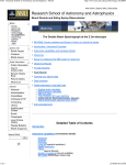
9.1.2 Interior of control unit for single pump pumpstation Aqualift F (schematic / not dimensioned)
1. Holes in interior of control unit for wall mounting with screws
2. Jacks for power connection
3. Location for battery (available as accessory)
4.1 Jacks for motor (pump)
4.2 Jacks for temperature control cables for motor (pump)
5. Jacks for float switches
6. Jacks for warning and alarm connections
Text from the illustration:
Bei Akkuwechsel Gerät spannungsfrei schalten = Unplug control unit before changing batteries
Schutz = Protection
Motorschutzschalter = Motor protection switch
Alarm ein /aus = Alarm on / off
Niveaueingänge = Float switch cabler
Thermoschutz = Thermal protection
Ausgang = Output Max Störung = Problem Alarm = Alarm
Installationsseitige Vorsicherung = On-site fuse Max 16 Amp
30
9. Control unit
9.1.3. Single unit
Text from the illustrations:
601 = Pump start delay time
602 = Max running time
603 = Pump stop delay time
Alarm Ein Aus = On Off
Jeweils 2x 1mm2 = 2 x 1mm2 each
Schwimmerschalter = Float switches
Netzanschlussklemmen = Power jacks
Schutz= Protection
Pumpe = Pump
Motorschutzschalter = Motor protection switch
Störmeldung = Warning notice
Pot. Freier Kontakt = potential free contact
Netzanschluss = Power Connection
Absicherung: siehe Typenschild = Safety / Fuse-see
Achtung!… = Caution! Connection only to be made by a
licensed professional electrician
Follow VDE and EVU protection guidelines
Control units should not be installed in rooms / areas
which present an explosion risks
Before starting, set overload switch to Inenn setting
Check rotation of pumps
31
9. Control unit
9.2 Control unit for double pump pumpstation Aqualift F
9.2.1 Description of displays and operational button on control unit
Normal operation
Information for User
Warnings
Information for Tradesman
Buttons
Hand - 0 - Auto (Pump 1)
Hand - 0 - Auto (Pump 2)
Alarm reset
Betrieb
green
power supply functioning
'Alarm' level
'On 2' level
'On 1' level
'Off' level
Pump1
Pump2
Phase
yellow
yellow
yellow
yellow
green
green
red
'Alarm' level reached
pump 2 on level reached
pump 1 on level reached
Pump off level reached
pump outlet 1 activated
pump outlet 2 activated
constant - phase not active
blinking - rotating field
problem
Pump 2 MSS/Temp red
constant - Pump 2 motor
protection switch activated
blinking - Pump 2 thermal
switch
Pump 1 MSS/Temp red
constant - Pump 1 motor
protection switch activated
blinking - Pump1 thermal
switch
Running time/level red
constant - running time
failure
blinking - level failure
Rotating switch
Rotating switch
button
Chooses Pump 1 operating type
Chooses Pump 2 operating type
Turns off alarm from level switch
Turns off level failure alarm
Motor protection switch 1
Motor protection switch 2
switch
switch
Turns of motor temperature alarm
Activated when pump overloads
Activated when pump overloads
The control buttons can be accessed by removing the transparent cover of the Aqualift F control
unit. The cover should only be removed and the control buttons accessed by a licensed
professional.
During the time that the transparent control unit cover is removed, the control units protection
class is reduced. In the case that a humid condition or splashing water may be present - first
unplug the control unit before removing the transparent cover.
The current for the motor protection switch must be set appropriately according to the
requirements of the motor and must not be set or changed by the operator / owner.
Be sure that the transparent cover is properly replaced and secured so that the proper protection
class is ensured.
32
9. Control unit
1. 2.Jacks for power connection
3.Location for battery (available as accessory)
4.1Jacks for motor (pump)
4.2 Jacks for temperature control cables for motor (pump)
5.Jacks for float switches
6.Jacks for warning and alarm connections
Text from the illustrations:
Motorschutzschalter = Motor protection switch
Alarm Ein2 Ein1 Aus = Alarm On2 On1 Off
Niveueingänge = Float switch inputs
Thermoschutz = Thermal switch
Ausgang = Outlet
Störung = Warning
Alarm = Alarm
Installationsseitige Vorsicherung Max . 25A = On-site fuse Max 25 Amp
33
9. Control unit
Text from the illustrations:
Pumpe = Pump
Störmeldung = Warning Notice
Pot freier Kontakt = potential free contact
Achtung!… = Caution! Connection only to be made by a
licensed professional electrician; Follow VDE and EVU
protection guidelines; Control units should not be installed in
rooms / araeas with explosion risks; before starting set
overload switch to Inenn setting; chech rotation of pumpfs;
Accumulator nach IEC = Accumulator according to IEC 6F22
Akku-Halter: Battery housing
Einschaltverzögerung: Pump start delay time
Grenzlaufzeit: Max running time
Nachlaufzeit: Pump stop delay time
Alarm = Alarm
Voralarm = Pre-Alarm
Schwimmerschalter = Float switches
Ein / Aus = On / Off
34
10. Replacement parts
Replacement part Group
Part
Number
Sewage pump
Type TPF 120 KE
Type TPF 154 KE
185-172
185-173
Pressure outlet
90mm OD single pump pressure fitting
63mm OD single pump pressure fitting
90mm OD double pump pressure fitting
63mm OD double pump pressure fitting
185-174
185-238
185-196
185-239
Pump seal
Lead pipe holder / clip(end piece)
Lead pipe double holder (middle piece)
PEHD-holder for lead pipe extension
Lead pipe (sold per meter)
185-183
185-216
185-264
185-194
185-273
Anti-return ball-valve
Ball-valve
Float switch
Float switch holder / clamp
185-179
185-217
185-164
185-169
Steal chain (sold per meter)
Hook for chain
185-182
185-181
Control unit for single pump TPF 120 KE
Control unit for single pump TPF 154 KE
Control unit for double pump TPF 120 KE
Control unit for double pump TPE 154 KE
Control unit single pump no motor protection
Switch
Control unit double pump no motor protection
switch
Motor protection switch for TPF 120 KE (2.5 Amps)
Motor protection switch for TPF 154 KE
(4.4 Amps)
Protection
Batteries (accessorie)
185-178
185-186
185-187
185-188
Electical control unit
Pump chamber parts
185-189
185-190
185-269
185-270
185-271
20230
see KESSEL sales catalog
35
11. Guarantee
1. In the case that a KESSEL product is defective, KESSEL has the option of repairing or replacing
the product. If the product remains defective after the second attempt to repair or replace the
product or it is economically unfeasible to repair or replace the product, the customer the has the
right to cancel the order / contract or reduce payment accordingly. KESSEL must be notified
immediately in writing of defects in a product. In the case that the defect is not visible or difficult to
detect, KESSEL must be notified immediately in writing of the defect as soon as it is discovered. If
the product is repaired or replaced, the newly repaired or replaced product shall receive a new
warranty identical to that which the original (defective) product was granted. The term defective
product refers only to the product or part needing repair or replacement and not necessarily to the
entire product or unit. KESSEL products are warranted for a period of 24 months. This warranty
period begins on the day the product is shipped from KESSEL to its customer. The warranty only
applies to newly manufactured products. Additional information can be found in section 377 and
378 of the HGB.
2. Wear and tear on a product will not be considered a defect. Problems with products resulting
from improper installation, handling or maintenance will also not be considered a defect.
01.01.2002
36
Important contacts / Info
Type
KESSEL Order Number
Production Date
Project description /
Building services supervisor
Address
Telephone / Fax
Planner
Address
Telephone / Fax
Contracted construction company
Address
Telephone / Fax
Contracted plumbing company
Address
Telephone / Fax
Contracted electrical company
Address
Telephone / Fax
System operator
Address
Telephone / Fax
Other remarks
The system operator, and those responsible, were present during the commissioning of this
system.
______________________________
Place and Date
37
Declaration of EC-Conformity
according to machine guide line 89/392/EWG of 14.06.1989 and modification guidelines 91/368/EWG of
20.06.1991, 93/44/EWG of 19.07.1993 and 93/68/EWG of 22.07.1993, low-voltage guideline 73/23/EWG and
guideline regarding electromagnetic compatibility 93/97/EWG of 29.10.1993
The producer
KESSEL GmbH, D-85101 Lenting
confirms that the product
KESSEL Aqualift® F pumping station
for underground / sub-surface installation
was developed and produced
in accordance with the following norms:
EN 292
VDE 31001
VDE 0113
EN 55082-2
EN 55011
EN 55014
EN 60335
Lenting, 01.01.1999
38
Everything for drainage
Backwater valves and cleanouts
Polymer and cast iron drains
Volatile liquid traps
Lifting stations, pumps, warning and
control units
Rainwater management systems
Grease separators
Oil/fuel and coalescence separators
Inspection chambers
Custom projects for industrial
applications
39