1
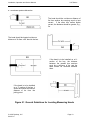
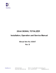
Installation, Operation and Service Manual
LKP Series
obtained. The final head position may yield voltages of 19 V at channels 1 and 3, and
perhaps 13 V at channels 2 and 4.
The channel voltages depend on several factors, such as total bus current, bus shape,
proximity to other bus bars, and channel coil resistance. In practice, it may prove impossible
to obtain full-equalized channel voltages because of a severe magnetic environment or lack
of space for moving the head. In this case, the best position should be found; then all
channels must be checked to see that all are within the limits of +3 V to +30 V (+3 V to 25V
for LKP-12). If these limits are exceeded, another location should be selected. If other
locations are not available, consult the factory regarding forced air cooling of the overloaded
channels, or replacing the system with a larger unit.
Figure 5.4 Magnetic Centering
© 2010 DynAmp, LLC
041610 J
Page 19