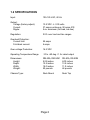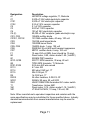
1
ASTRON CORPORATION
SERVICE MANUAL
FOR: RM-50A, RM-50M, RS-50A, RS-50M
Originally had a 2009 schematic that did not match the parts list.
Transcribed and updated by Robert W. Meister WA1MIK August 2015.
ASTRON CORPORATION
9 AUTRY
IRVINE, CA 92618
PH: (949) 458-7277, FAX: (949) 458-0826
SECTION 1: GENERAL INFORMATION
1.1 INTRODUCTION
The ASTRON "50" series are heavy-duty power supplies capable of
supplying 37 amps continuous at 13.8 VDC from 115 VAC line voltage. The
output voltage is adjustable from approximately 11-15 VDC.
These supplies are protected against overload and short circuits by foldback current limiting. The load is protected against over-voltage by a
"crowbar" circuit, which initiates latched current limiting upon over-voltage,
dropping the output voltage to a safe level.
The RS-50A and RM-50A are identical to the RS-50M and RM-50M except
the "A" models do not have meters.
Two meters on the RM-50M and RS-50M front panel provide measurement
of voltage and current being supplied to the load. The current meter is
calibrated for 0-50 amps and the voltmeter reads 0-15 VDC. The power
switch on the front panel controls AC power to the supply and indicates the
presence of AC power when in the ON position. AC line surge protection is
provided internally and a 10 amp AC line fuse is accessible at the rear
panel.
Page 1
1.2 SPECIFICATIONS
Input:
105-125 VAC, 60 Hz
Output:
Voltage (factory adjust):
Current:
Ripple:
13.8 VDC +/- 0.05 volts
37 amps continuous, 50 amps ICS
5 mv maximum (full load, low line)
Regulation:
0.5% over load and line ranges
Overload Protection:
Current limit:
Fold-back current:
55 amps
4 amps
Over-voltage Protection:
16.5 VDC
Operating Temperature Range:
-10 to +40 deg. C. for rated output
Dimensions:
Height:
Depth:
Width:
Weight:
RM-50A, RM-50M
5.25 inches
12.5 inches
19.0 inches
50 pounds
RS-50A, RS-50M
6.00 inches
13.5 inches
11.0 inches
46 pounds
Chassis Type:
Rack Mount
Desk Top
Page 2
1.3 PRECAUTIONS
WARNING: HAZARDOUS VOLTAGES
The RM-50M/RS-50M contains voltages that may be lethal. The case of the
supply should not be removed without first disconnecting the AC supply.
Servicing should be done only by qualified technicians.
CAUTION: HANDLE WITH CARE
The weight of the RM-50M is 50 lbs so care is needed when removing it
from the rack mount.
CAUTION: HEAT SINK TEMPERATURE
Under some conditions the power supply heat sinks may reach high
temperatures. Handle with extreme care after prolonged operation.
CAUTION: VENTILATION
Do not operate this power supply in a concealed cabinet.
CAUTION: EXTERNAL BATTERY FUSING
If a battery is used for standby operation and is connected directly across
the power supply output, always connect a fuse and a blocking diode
between the power supply and the battery. Failure to follow this practice
could result in battery destruction and/or damage to the power supply
should the crowbar circuit trigger, which will place a virtual short circuit
across the battery. The battery should be disconnected when servicing the
power supply to prevent accidental shorting of the battery voltage.
Page 3
SECTION 2: CIRCUIT DESCRIPTIONS
2.1 LINE CIRCUIT AND RECTIFIERS
Refer to RM-50M/RS-50M Schematic on page 14.
The 115 VAC line voltage is supplied to transformer 8401 via the 10 amp
back panel mounted fuse F1 and front mounted switch SW1. When the
switch is on the indicator lamp indicates the presence or absence of 115
VAC. VR1 (MOV) provides protection against short duration high voltage
line transients.
Diodes CR101 and CR102 in conjunction with capacitor C5 form a high
current rectifier circuit for the power supply load. CR1, CR2 and C1 provide
DC voltage for the voltage regulator, crowbar and series pass drive circuits.
CR6 provides over-voltage protection for the regulator IC. CR7 protects the
power transistors against over voltage when power is turned off and an
external battery is connected across the load.
2.2 SERIES PASS POWER CIRCUIT
The series pass power circuit is made up of two banks of four 2N3771
transistors operating in parallel as illustrated in the circuit showing Q101
and Q102. Resistors R101, R102, ... are provided in the emitter circuits for
balancing the load among the eight transistors. CR7 provides protection
against reverse voltage across the transistors. Q109 provides base current
drive to the eight series pass transistors. It in turn, is driven by the voltage
regulator circuitry contained on the PC board.
Page 4
2.3 VOLTAGE REGULATOR
The uA723/LM723 IC (A1) in conjunction with associated circuitry, performs
the function of voltage regulator, fold-back current limiting and provides
drive current for the series pass circuit. See IC manufacturer's data book
for details on the internal operation of the uA723/LM723.
Refer to Simplified schematic on page 13.
Voltage regulation is accomplished within the IC by comparing the scaled
down supply output voltage (from the wiper of R5) to an internal 7.2 volt
reference voltage. The reference voltage (pin 6) is connected to the noninverting input (pin 5) of an internal op amp. The scaled down power supply
voltage from R5 is connected to the op amp inverting input (pin 2) providing
negative feedback.
If the power supply output voltage attempts to change, the IC output at pin
10 changes in the opposite direction, thus maintaining the output voltage
constant for a given setting of R5.
The IC internal op amp maintains null between its two inputs, i.e. the
inverting input through negative feedback, is maintained equal to the 7.2
volt reference. Therefore the output supply voltage will go up or down to
accommodate a change in the setting of R5. This allows the output voltage
to be adjusted to any value between 11 and 15 volts with the voltage
division ratio provided by the combination of R5, R6 and R7.
The current from the 723 IC is amplified by Q2 and applied to the base of
the 2N3771 series pass drive transistor. As noted in the voltage chart on
the schematic, the regulator IC output voltage increases as power supply
loading increases to compensate for the increased voltage drop across R1,
R1X and the series pass circuit.
Page 5
At full load, the voltage at the current limit input of the IC (pin 2) is around
14 volts as determined by the ratio of R4 and R3, R3X which sets the point
at which current limiting begins. As the load is increase above full load, the
differential between pins 2 and 3 (current sense input) increases until the
internal current sense transistor begins to conduct (at 52 amps, factory set
by R3X). Fold-back current limiting then occurs and the load current and
output voltage decrease with decreasing load resistance until the short
circuit current of 4 amps is reached. The short circuit current is factory set
by selecting the value of resistor R1X. Diodes CR3 and CR6 prevent
damage to the circuits by capacitive discharge or an external battery when
power is turned off. CR4 stabilizes current in the limiting mode, preventing
overheating due to current drift.
2.4 CROWBAR CIRCUIT
The power supply load is protected from over-voltage by the crowbar
circuit, which triggers at 16.5 volts. Zener diode CR4 maintains a voltage
5.6 volts lower than the power supply voltage at the emitter of Q1 while the
voltage at the base of the transistor is determined by the voltage divider R8
and R10. As the output voltage increases, the voltage at the emitter of Q1
increases by the same amount while the base voltage increases according
to the ratio of R8 and R10. At 16.5 volts, the base becomes more negative
than the emitter to the extent that Q1 conducts, producing a voltage across
R11 sufficient to trigger SCR1. When triggered, SCR1 acts as a virtual
short circuit causing current limiting and subsequent low voltage output.
Once triggered on, the SCR will continue to conduct until power is turned
off.
Capacitors C6 and C102 in the gate circuit of SCR1 prevent false triggering
from voltage transients.
Page 6
2.5 METER CIRCUITS
The current meter uses R102 as a meter shunt for measuring relative
current. Although only one eighth of the current is measured, the meter is
calibrated at full load by adjustment of R103 and therefore accurately
indicates the full load current. The voltmeter is calibrated by R104 after
setting the supply output voltage to 13.8 VDC with a calibrated external
meter.
SECTION 3: INSTALLATION
3.1 GENERAL
The RM-50A/RM-50M is supplied in a rack mount configuration and may be
mounted in any standard 19" rack mount cabinet with suitable ventilation.
The power supply generates appreciable heat when operated at full load
and requires an adequate airflow for cooling. It should always be mounted
with adequate clearance above and below to provide convective cooling.
Forced-air cooling may be required if other equipment generating relatively
high levels of heat is enclosed in the came cabinet. DC output wiring
should be of sufficient gauge to carry the current without excessive voltage
drop.
CAUTION
If a battery is used for standby operation and is connected directly across
the power supply output, always connect a fuse and a blocking diode
between the power supply and the battery. Failure to follow this practice
could result in battery destruction and/or damage to the power supply
should the crowbar circuit trigger, which will place a virtual short circuit
across the battery. The battery should be disconnected when servicing the
power supply to prevent accidental shorting of the battery voltage.
Page 7
SECTION 4: SERVICING
4.1.1 PRECAUTIONS
See Section 1.3.
4.1.2 TECHNICAL BULLETINS
From time to time, Technical Bulletins may be issued to enable updating of
equipment, provide information or to meet specific operational
requirements.
4.2 MECHANICAL
Access to the inside of the power supply for servicing may be obtained by
removing the six screws holding the top lid in place.
4.3 TEST AND ADJUSTMENT
All power supply parameters previously defined are factory adjusted and
normally will not require field adjustment. However, if certain components
are replaced or a malfunction is suspected, it may be necessary to perform
test and adjustment as defined in the following sections.
4.3.1 TEST EQUIPMENT REQUIRED
Voltmeter
Ammeter
Variable load
DC, 0-25 volts, sensitivity min. 20K ohms/volt
DC, 0-100 amps
0-100 ohms, rated at 70 amps minimum
4.3.2 OUTPUT VOLTAGE
R5 controls the output voltage and may be adjusted to set it to exactly 13.8
volts. If calibration of the front panel meter is suspect, use a known
accurate voltmeter for this adjustment, then calibrate the front panel meter
by adjusting R104.
Page 8
4.3.3 OUTPUT CURRENT
Output current at rated load may be checked by connecting the ammeter in
series with the load and adjusting the load for 37 amps. If the panel
mounted current meter does not read 37 amps, it may be recalibrated by
adjusting R103.
4.3.4 FOLD-BACK CURRENT
To check the fold-back current limiting point, connect the load to the output
and adjust for 52 amps. Decreasing the resistance of the load should cause
current to begin decreasing to 4 amps when the load reaches zero
resistance. Resistor R3 in parallel with R3X (factory selected) determines
the current limit point, i.e. the point where fold-back begins. Resistor R1 in
parallel with R1X determines the short circuit limit of 4 amps.
In the event of component replacement, it may be necessary to change the
values of R3X and R1X to reset these currents to design limits. Increasing
the value of either network decreases their respective current values.
4.3.5 CROWBAR VOLTAGE
To test for proper operation of the crowbar circuit, momentarily short across
resistor R7. This causes the output voltage to rise to approximately 17 volts
and should trigger the crowbar circuit.
Page 9
4.4 TROUBLESHOOTING
Refer to RM-50M/RS-50M Schematic on page 14.
Remove the top cover to gain access to the inside of the power supply and
check for proper operation of the transformer primary and secondary
circuits including the power rectifier circuit CR101, CR102 and capacitor C5
(large chassis-mounted electrolytic capacitors). A check of voltage present
at the I/O pins of IC A1 (uA723/LM723 voltage regulator) as compared to
the A1 voltage chart shown on the schematic should provide an indication
of the nature of the problem. If the voltage regulator is suspect, it can be
replaced by removing the two PC board mounting screws and replacing the
IC in the socket provided.
Since the heat sink mounted series pass power transistors operate at high
junction temperatures, a failure in this area is most probable. Junctions
may be checked for shorts or opens by disconnecting one end of the 0.05
ohm balancing resistors (R101, R102, ...) in their emitter circuits.
Note that due to the use of R102 as a meter shunt to measure relative
current rather than absolute current, a failure of Q102 will cause false
current readings. An open series pass transistor may not be apparent in
terms of the current reading but may be detected by a significant drop in its
case temperature. A shorted transistor will cause either current limiting or
crowbar triggering.
SECTION 5: PARTS LIST
Editor's Note: Some of the parts have been replaced as the power supplies
went through design revisions. The parts list below closely matches the
1996 schematic at the end of this file but I think the manual was written
prior to 1990. The schematic that originally came with the file was dated
2009.
Page 10
Designation
A1
C1
C101
C102
C2
C3
C4
C5 (2)
CR1, CR2
CR101, CR102
CR3
CR4
CR5, CR8
CR6
CR7
F1
IM
Q1
Q101-Q109
Q2
R101-R108
R113
R114
R115
R5
RXXX
SCR1
SW1
T1
VM
VR1
Description
LM723CN voltage regulator, TI, Motorola
2,200 uF 35V radial electrolytic capacitor
2,200 uF 16V electrolytic capacitor
0.33 uF 50V ceramic capacitor
0.1 uF 50V capacitor
0.001uF 100V capacitor
100 uF 25V electrolytic capacitor
50,000 uF 25V computer grade electrolytic cap.
1N5404 rectifier diode
1N1184A rectifier diode, 40 amp, 100 volt
1N4148 small signal diode
1N5232B zener diode
1N4002 diode, 1 amp, 100 volt
P6KE39A 39 volt 600 watt transient suppressor
MR751 rectifier diode, 6 amp, 100 volt
10 amp 250 volt MDL fuse (should be 12 amp)
Panel meter, 0-50, Astron model 1-50 (1mADC)
2N3906 PNP transistor
2N3771 NPN transistor, 30 amp, 40 volt
TIP29 NPN transistor, TI, Motorola
0.05 ohm 5W wire-wound
4.7 ohm 2W
500 ohm 0.5W pot, 1T
20k 0.5W pot, 1T
1k 0.5W pot, 1T
All other resistors, 0.5W 5% CF
SO565J 50 amp, 50 volt SCR
LRA211RSB/125N illuminated AC rocker switch
Transformer, Astron 8401
Panel meter, 0-15, Astron model 1-15 (1mADC)
V130LA10A MOV, 10 amp, 130 volt, GE
Note: Other manufacturer's equivalent capacitors and resistors with the
same specifications may be substituted for those specified above. Industry
standard semiconductors from several manufacturers may be used for
replacement.
Page 11
SECTION 6: PARALLEL
6.1 PARALLEL OPERATION
Two units may be set up in parallel to double the current capacity by using
the following procedure.
Connect the negative output terminals of two power supplies using 10
gauge or large wire (depending on the distance between the units).
Connect the positive output terminals using the same gauge and same
length wire.
The output voltage of each unit must be set to the same voltage.
Connect a wire from the red terminal, marked "FOR PARALLEL
OPERATION ONLY" on power supply "A" to the same red terminal on
power supply "B".
Connect the negative load to the negative output terminal of power supply
"A" and connect the positive load to the positive output terminal of power
supply "B".
This will allow the power supplies to track and share the load equally.
Page 12
Page 13
Page 14