Transcript
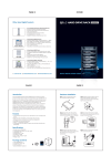
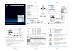
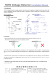
Page 4
Front Cover
Page 5
Version 1.0
Product Family/ Produkt Familie/ Famile de produit/ Familia de productos/
Famigilia di prodotti/
Note.1
2.5” Hard disk Enclosure with 10-in-1 Card
Reader/ Writer
Input "0000" and press "ENTER" for 12 times in order to next process.
Blue backlight LCD Panel with Status and Battery Indicator
Three memory card slots supports, CF I/II, MD, SM, MS, MS-PRO, SD,
Mini-SD, MMC Card, XD, etc.
USB 2.0 host interface, backward compatible with USB 1.1.
Built-in Rechargeable Lithium-Ion Battery
Single button backup from memory card to hard drive
Durable and light weight Aluminum Case with Carry bag
Pass word:0000
MS1U
Note.2
The number of physical drives in a specific RAID set determines the RAID
levels that can be implemented with the RAID set.
- RAID 0 requires 1 or more physical drives per RAID set.
- RAID 1 requires at least 2 physical drives per RAID set.
- RAID 1 + Spare requires at least 3 physical drives per RAID set.
- RAID 3 requires at least 3 physical drives per RAID set.
- RAID 5 requires at least 3 physical drives per RAID set.
- RAID 3 + Spare requires at least 4 physical drives per RAID set.
- RAID 5 + Spare requires at least 4 physical drives per RAID set.
IR35S1
Triple Interface RAID Subsystem
Hardware RAID Engine, supports RAID 0 and JBOD
Triple Host Interface: USB 2.0 + FireWire 400 + Firewire 800
Drive Interface: 2x 3.5" SATA Harddrive
Fan and Temperature failure detectors with purple warning LED
MS2C1
USB 2.0 & SATA Combo RAID Subsystem
Hardware RAID Design, supports RAID 0, 1
Host Interface: eSATA port & USB 2.0
Drive Interface: 2 x 3.5” SATA Hard Disk
Hot-Swappable Removable Tray
Data Auto-Rebuilding
Hard Disk, Fan and Temperature failure detectors
No Driver Required
Note.3
MS2UT
Stripe size default is 64k, it could adjust to 4k or 128k mode under stripe size, actually
128K size will get much better performance.
QUICK INSTALLATION
GUIDE
SCSI to SATA RAID 5 Subsystem
Hardware RAID Design, supports RAID 0, 1, 3, 5, 0+1, JBOD & Hot Spare Disk
Host Interface: SCSI Ultra 320
Drive Interface: 5 x 3.5” SATA
Hot-Swappable Removable Tray Hard Disk
Data Auto-Rebuilding
Hard Disk, Fan and Temperature failure detectors to ensure system stability
Note.4
Please refer to the CD enclosed for detail user's manual.
Your ONE-STOP Storage Solution Provider
www.sansdigital.com
MR5S1
Page 1
IR35S1 system includes the following:
Page 2
Quick Volume / RAID Setup
Hardware Installation
Please contact our distributors in case of any missing or damaged items.
Front Panel
Quantity
Rear Panel
H
Item
Page 3
D
D
H
D
D
e
ol
LE
H
Fan
or
at
te
ta
S
ic
1
ck
PCI Bracket RS232 Cable
Lo
1
d
In
RS232 cable
D
1
LE
User’s Guide & CD Title
D
5
r
to
ec
et
D
re
tu
ra
Removable Tray Module
n
Fa
1
pe
m
Te
er
ow
P
IR35S1
RS232 Port
PCI Bracket
RS232 cable
VHDCI-SCSI
The serial port on the controller's back plane can be used in VT-100 mode.The RAID subsystem comes
with 10-pin RS-232 serial port, which, using a null modem cable, can be connected to any COM port on a
host computer for VT-100 terminal management purposes. It can also transfer to external for a VT-100
compatible terminal(or a PC running appropriate terminal emulation software). The firmware-based
terminal array management interface can access the array through this RS-232 port.
Note : You may allow connecting a terminal while the RAID subsystem is at power on state.
To ensure proper communications between the RAID subsystem and the VT-100 Terminal Emulation.
Please configure the VT-100 terminal emulation settings to the values shown below :
SCSI Port
Terminal requirement
Connection
Null-modem cable
Baud Rate
115, 200
Data bits
8
Stop
1
Flow Control
None
Power
Host Connection
IR35S1 Rear Panel
Installing HDD in the Removable Tray Module
1
PC Power Supply
1
PCI bracket
RS232 Cable
3 SCSI Card
2
1. Demount the transport holder.
2. Mount the HDD into the tray.
4
Power On
IR35S1
COM 1
RS232Card
COM 2
2
Connect to
Terminal
3
Motherboard
Total X Disks
RAID 0
RAID 1
RAID 0+1
RAID 1+Spare
RAID 0+1+Spare
RAID 3
RAID 3+Spare
RAID 5
RAID 5+Spare
Note.2
(Press key "X" Button)
4
SCSI Cable
Power Supply
Quick Volume and
RAID Set Setup
Password
Note.1
RS232 cable
Note
Available Capacity : xxx GB
Selected Capacity : xxx GB
Select Stripe Size
Note.3
Create Vol / RAID Set
Yes
No
Foreground(Faster Completion)
Background(Instant Available)
2
It will cause hard disk push towards the backplane and the tray handle is
unable to rotate once the screws do not properly fixed.
IR35S1 did not set any default RAID level, hence, please set your desire RAID level after booth the device.
Please be noted when you set the RAID level plese make sure all hard disk inside the device is “Green” light.
PCI Bracket RS232 cable
SCSI Card
3